EP2095849A1 - Exercise machine - Google Patents
Exercise machine Download PDFInfo
- Publication number
- EP2095849A1 EP2095849A1 EP09153663A EP09153663A EP2095849A1 EP 2095849 A1 EP2095849 A1 EP 2095849A1 EP 09153663 A EP09153663 A EP 09153663A EP 09153663 A EP09153663 A EP 09153663A EP 2095849 A1 EP2095849 A1 EP 2095849A1
- Authority
- EP
- European Patent Office
- Prior art keywords
- cable
- exercise machine
- machine according
- drum
- foregoing
- Prior art date
- Legal status (The legal status is an assumption and is not a legal conclusion. Google has not performed a legal analysis and makes no representation as to the accuracy of the status listed.)
- Granted
Links
Images
Classifications
-
- A—HUMAN NECESSITIES
- A63—SPORTS; GAMES; AMUSEMENTS
- A63B—APPARATUS FOR PHYSICAL TRAINING, GYMNASTICS, SWIMMING, CLIMBING, OR FENCING; BALL GAMES; TRAINING EQUIPMENT
- A63B23/00—Exercising apparatus specially adapted for particular parts of the body
- A63B23/035—Exercising apparatus specially adapted for particular parts of the body for limbs, i.e. upper or lower limbs, e.g. simultaneously
- A63B23/12—Exercising apparatus specially adapted for particular parts of the body for limbs, i.e. upper or lower limbs, e.g. simultaneously for upper limbs or related muscles, e.g. chest, upper back or shoulder muscles
-
- A—HUMAN NECESSITIES
- A63—SPORTS; GAMES; AMUSEMENTS
- A63B—APPARATUS FOR PHYSICAL TRAINING, GYMNASTICS, SWIMMING, CLIMBING, OR FENCING; BALL GAMES; TRAINING EQUIPMENT
- A63B21/00—Exercising apparatus for developing or strengthening the muscles or joints of the body by working against a counterforce, with or without measuring devices
- A63B21/06—User-manipulated weights
- A63B21/062—User-manipulated weights including guide for vertical or non-vertical weights or array of weights to move against gravity forces
- A63B21/0626—User-manipulated weights including guide for vertical or non-vertical weights or array of weights to move against gravity forces with substantially vertical guiding means
- A63B21/0628—User-manipulated weights including guide for vertical or non-vertical weights or array of weights to move against gravity forces with substantially vertical guiding means for vertical array of weights
-
- A—HUMAN NECESSITIES
- A63—SPORTS; GAMES; AMUSEMENTS
- A63B—APPARATUS FOR PHYSICAL TRAINING, GYMNASTICS, SWIMMING, CLIMBING, OR FENCING; BALL GAMES; TRAINING EQUIPMENT
- A63B21/00—Exercising apparatus for developing or strengthening the muscles or joints of the body by working against a counterforce, with or without measuring devices
- A63B21/15—Arrangements for force transmissions
- A63B21/151—Using flexible elements for reciprocating movements, e.g. ropes or chains
- A63B21/154—Using flexible elements for reciprocating movements, e.g. ropes or chains using special pulley-assemblies
-
- A—HUMAN NECESSITIES
- A63—SPORTS; GAMES; AMUSEMENTS
- A63B—APPARATUS FOR PHYSICAL TRAINING, GYMNASTICS, SWIMMING, CLIMBING, OR FENCING; BALL GAMES; TRAINING EQUIPMENT
- A63B21/00—Exercising apparatus for developing or strengthening the muscles or joints of the body by working against a counterforce, with or without measuring devices
- A63B21/40—Interfaces with the user related to strength training; Details thereof
- A63B21/4027—Specific exercise interfaces
- A63B21/4033—Handles, pedals, bars or platforms
- A63B21/4035—Handles, pedals, bars or platforms for operation by hand
-
- A—HUMAN NECESSITIES
- A63—SPORTS; GAMES; AMUSEMENTS
- A63B—APPARATUS FOR PHYSICAL TRAINING, GYMNASTICS, SWIMMING, CLIMBING, OR FENCING; BALL GAMES; TRAINING EQUIPMENT
- A63B21/00—Exercising apparatus for developing or strengthening the muscles or joints of the body by working against a counterforce, with or without measuring devices
- A63B21/02—Exercising apparatus for developing or strengthening the muscles or joints of the body by working against a counterforce, with or without measuring devices using resilient force-resisters
- A63B21/023—Wound springs
-
- A—HUMAN NECESSITIES
- A63—SPORTS; GAMES; AMUSEMENTS
- A63B—APPARATUS FOR PHYSICAL TRAINING, GYMNASTICS, SWIMMING, CLIMBING, OR FENCING; BALL GAMES; TRAINING EQUIPMENT
- A63B21/00—Exercising apparatus for developing or strengthening the muscles or joints of the body by working against a counterforce, with or without measuring devices
- A63B21/40—Interfaces with the user related to strength training; Details thereof
- A63B21/4041—Interfaces with the user related to strength training; Details thereof characterised by the movements of the interface
- A63B21/4043—Free movement, i.e. the only restriction coming from the resistance
-
- A—HUMAN NECESSITIES
- A63—SPORTS; GAMES; AMUSEMENTS
- A63B—APPARATUS FOR PHYSICAL TRAINING, GYMNASTICS, SWIMMING, CLIMBING, OR FENCING; BALL GAMES; TRAINING EQUIPMENT
- A63B21/00—Exercising apparatus for developing or strengthening the muscles or joints of the body by working against a counterforce, with or without measuring devices
- A63B21/40—Interfaces with the user related to strength training; Details thereof
- A63B21/4041—Interfaces with the user related to strength training; Details thereof characterised by the movements of the interface
- A63B21/4045—Reciprocating movement along, in or on a guide
-
- A—HUMAN NECESSITIES
- A63—SPORTS; GAMES; AMUSEMENTS
- A63B—APPARATUS FOR PHYSICAL TRAINING, GYMNASTICS, SWIMMING, CLIMBING, OR FENCING; BALL GAMES; TRAINING EQUIPMENT
- A63B23/00—Exercising apparatus specially adapted for particular parts of the body
- A63B23/035—Exercising apparatus specially adapted for particular parts of the body for limbs, i.e. upper or lower limbs, e.g. simultaneously
- A63B23/03508—For a single arm or leg
-
- A—HUMAN NECESSITIES
- A63—SPORTS; GAMES; AMUSEMENTS
- A63B—APPARATUS FOR PHYSICAL TRAINING, GYMNASTICS, SWIMMING, CLIMBING, OR FENCING; BALL GAMES; TRAINING EQUIPMENT
- A63B23/00—Exercising apparatus specially adapted for particular parts of the body
- A63B23/035—Exercising apparatus specially adapted for particular parts of the body for limbs, i.e. upper or lower limbs, e.g. simultaneously
- A63B23/12—Exercising apparatus specially adapted for particular parts of the body for limbs, i.e. upper or lower limbs, e.g. simultaneously for upper limbs or related muscles, e.g. chest, upper back or shoulder muscles
- A63B23/1209—Involving a bending of elbow and shoulder joints simultaneously
Definitions
- the present invention relates to an exercise machine for developing motor abilities and muscular strength.
- the present invention relates to an exercise machine in which the user acts on a resistant load using a grip element connected to a flexible cable.
- the present invention relates to a functional strength exercise machine.
- Functional strength machines allow the user to perform complex movements starting from free positions, simulating movements which are regularly performed when carrying out any activity, for sport or work.
- the grip element is connected to the resistant load by a flexible cable and allows the performance of movements which are free in space.
- the cable is wound around a plurality of pulleys in such a way as to form a path which is closed in a loop, more or less complex depending on the number of grip elements and load units involved.
- it will therefore be necessary to join the ends of the flexible cable, maintaining as far as possible the evenness and continuity of the outer section of the cable at the joint.
- the cable is wound around pulleys in one direction and in the opposite direction, with the point where the ends of the cable join consequently passing from one position to another around the pulleys.
- the present invention therefore has for a technical purpose to overcome the above-mentioned disadvantages, providing an exercise machine in which the cable has a fixed joint, in such a way that the machine preserves the initial configuration at the end of training and in which the joint is simple to make and mount.
- the present invention has for an aim to provide a strength machine which involves limited and simple operations for its production.
- Another aim of the present invention is to provide an exercise machine which has a simple structure, is easy to make in practice, operates safely and effectively and is relatively inexpensive. Accordingly, said technical purpose and aims are achieved by the present exercise machine for developing motor abilities and muscular strength, of the type comprising at least one supporting frame, at least one flexible cable wound on a plurality of pulleys rotatably supported by the frame and connected to at least one resistant load, at least one grip element connected to the cable and designed to be operated by a user in order to perform an exercise, the machine being characterised in that it comprises at least one return device, to which the ends of the cable are connected, said device designed to return the cable to the initial configuration after an exercise has been performed.
- the numeral 1 denotes an exercise machine in accordance with the invention, which can be used to perform exercises for developing motor abilities and muscular strength.
- the machine 1 has a frame 2, for the sake of simplicity only partly represented in the drawings, which supports a plurality of pulleys 3a, 3b, 3c, 3d in such a way that they can rotate freely according to respective axes which are parallel with each other and preferably horizontal.
- the machine 1 comprises a flexible cable 4 wound on the plurality of pulleys 3a, 3b, 3c, 3d.
- Said plurality of pulleys comprises in particular at least two consecutive pulleys 3a and 3b, one mounted at the top and one at the bottom, vertically aligned, so as to form a vertical operating segment 4a for the cable 4, between the pulleys 3a and 3b.
- said plurality of pulleys comprises two consecutive pulleys 3a and 3c, or 3b and 3d, rotatably mounted relative to the frame 2 and horizontally aligned, so as to form a horizontal operating segment 4c or 4b for the cable 4, respectively between the pulleys 3a and 3c, or 3b and 3d.
- the machine 1 comprises at least one grip element 5a connected to the cable 4 along the operating segments described above, designed to be operated by a user in order to perform exercises.
- the grip element 5a slides freely and can be selectively rigidly connected to the cable 4.
- the grip element 5a comprises a cylindrical element 6 having an axial cavity through which the cable 4 passes in a selectively sliding fashion.
- the machine 1 comprises a resistant load, labelled 7 as a whole, supported by the frame 2 in such a way that it can slide freely and connected to the flexible cable 4 by means of the idle pulleys 8, 8a, 8b.
- the resistant load 7 is gravitational, with adjustable intensity, of the weight stack-style known type.
- a plurality of plates 9 is supported by the frame 2 in such a way that they slide freely along a substantially vertical straight guide 10.
- the machine 1 comprises a bracket 11 rigidly fixed on the first plate 9a, at the top of the resistant load 7.
- the idle pulleys 8 are rotatably supported on the bracket 11.
- the exercise machine also comprises a cylindrical bar 12, integral with the bottom of the bracket 11, having a set of holes not illustrated in the drawing arranged transversally along its axis, the bar engaging in a channel 12a formed by central holes made in each of the plates 9.
- Each plate 9 has a hole communicating with the channel 12a, opposite and aligned with a respective hole in the bar 12, not illustrated in the drawing.
- the machine 1 comprises a return device 14 to which a first end and a second end 4' and 4'' of the cable 4 are fixed.
- Said return device 14 comprises a drum 15 rotatably supported by the frame 2, on a preferably horizontal axis 15a, around which a first end portion of the cable 4 comprising the first end 4' is wound in a first winding direction, and a second end portion of the cable 4 comprising the second end 4" is wound in a second winding direction which is opposite to the previous winding direction.
- the ends 4' and 4" are fixed to the drum 15 in a known way.
- the drum 15 has two radial cylindrical cavities designed to house respectively the first and the second end 4', 4'' which are fixed to the drum 15 by corresponding fixing pins not illustrated in the accompanying drawings.
- the return device 14 comprises an elastic element 16 between the drum 15 and the frame 2, designed to return the cable 4 to a configuration which shall be defined as the "initial configuration", at the end of any exercise involving operation of the grip element 5a.
- the elastic element 16 is a spring 17 with a first end 18 integral with the frame 2 and a second end 19 integral with the drum 15.
- said spring 17 is of the cylindrical helical extension type, whilst the first end 18 and the second end 19 consist of two fixing eyelets.
- the first end 18 is fixed to the frame 2 by a corresponding ring 18a.
- the return device 14 also comprises a secondary connecting cable 20 between the drum 15 and the spring 17.
- the drum 15 has a radial seat 21, formed by flared surfaces 21a, designed to rigidly house a first end 22 of the secondary cable 4, whilst the second end 23 of the latter is connected to the second end 19 of the spring 17 ( Figure 2 ).
- the secondary cable 20 is wound around a secondary pulley 24 rotatably mounted on the frame 2 in such a way that it rotates relative to a preferably horizontal axis and is such that it causes the spring 17 to apply its return action in a vertical direction.
- the exercise machine 1 comprises three grip elements 5a, 5b and 5c, connected to the same number of operating segments of the cable 4, there being an upper horizontal segment 4c relative to the resistant load 7, a vertical segment 4a and a lower horizontal segment 4b relative to the resistant load 7.
- the consecutive pulleys which delimit the vertical operating segment will be the same as those delimiting an end of the two horizontal segments.
- the following is a description of the path of the cable 4 in a preferred embodiment of the machine 1, in accordance with the present invention, considering the machine in the initial configuration, that is to say, before the exercise is performed, or at the end of performance of the exercise.
- the first end portion is wound around the drum 15.
- the cable 4 then passes around the idle pulley 8, integral with the resistant load 7, after which it passes around the pulleys 3c, 3a, 3b and 3d respectively forming the following operating segments: upper horizontal 4c, vertical 4a and lower horizontal 4b.
- the cable 4 passes around the idle pulleys 8a, 8b then the second end 4" of the cable is wound around and secured on the drum 15.
- FIGS 3 and 4 show further embodiments of the return device 14.
- the return device 14 comprises a spring 17 of the cylindrical helical torsion type, or of the spiral type.
- the return device 14 also comprises a secondary drum 25 supported on the frame 2 in such a way that it rotates relative to a preferably horizontal axis.
- the secondary cable 20 has a first end 22 fixed to the drum 15 in a respective radial seat 21 and has an end portion 23', ending with the second end 23, wound around the secondary drum 25 to which the second end 23 is fixed.
- the spring 17 comprises a first and a second end, respectively labelled 18 and 19, which delimit its circumferential development.
- the first end 18 is rigidly fixed to the frame 2 whilst the second end 19 is fixed so that it is integral with the secondary drum 25, in such a way that the spring 17 applies a return action for the secondary drum 25 in the circumferential direction according to an axis substantially coinciding with the axis of the secondary drum, consequently returning the return device 14 to the initial configuration by means of the secondary cable 20.
- the spring 17 applies the return action according to a predetermined direction of rotation which depends on the direction with which the secondary cable 20 is wound relative to the secondary drum 25. Operation of the exercise machine 1 in accordance with the invention is intuitive and is described briefly below.
- the user While performing the exercise, the user moves the grip element 5a located at one of the cable 4 operating segments, the upper horizontal segment 4c, the lower horizontal segment 4b or the vertical segment 4a, according to the muscles to be trained.
- the user's action on the cable 4 changes the machine 1 configuration relative to the initial configuration described above.
- the length of the selected cable operating segment is increased, consequently lifting the resistant load 7.
- the length of one of the end portions of the cable wound around the drum 15 is increased, with a simultaneous reduction in the length of the other end portion, wound around the drum 15 in the opposite direction, with consequent drum 15 rotation about its own axis.
- Drum 15 rotation in one direction rather than another depends on the type of exercise the user performs.
- the drum 15 direction of rotation associated with user action on the grip element 5c of the upper horizontal operating segment 4c of the cable 4 is opposite to that associated with user action on the grip element 5b of the lower horizontal operating segment 4b.
- drum 15 rotation generates, by means of the secondary cable 20, the spring 17 return action which tends to return the drum 15 itself to the initial configuration at the end of the exercise.
- the secondary cable 20 pulls the cylindrical helical extension spring 17.
- the presence of the flared surfaces 21a at the radial seat 21 allows drum 15 rotation, in one direction or the other even with considerable angles, without any risk of bending the secondary cable 20 with small bending radii, and therefore without any risk of damaging or breaking it.
- the secondary cable 20 causes the return action of the cylindrical helical torsion spring 17 or the spiral spring by means of secondary drum 25 rotation about its own axis.
- the length of the first and second end portions of the cable 4 wound on the drum in the initial configuration limits the extent of the movement of the grip element 5a which the user can perform. Obviously, the longer said length is, the greater the extent of movement of the grip element 5a and consequently the movement by the user will be.
- the exercise machine 1 disclosed returns to the initial configuration after each use and therefore it is in the same configuration each time the user begins exercising, maintaining the same behaviour for all training. This result is made possible by the return device 14 to which the cable 4 joint is suitably connected by fixing the ends 4' and 4". Moreover, the invention allows the cable joint to be made in a simple and rapid way. In addition to that, the exercise machine disclosed involves limited and rapid operations for its production.
Abstract
Description
- The present invention relates to an exercise machine for developing motor abilities and muscular strength. In particular, the present invention relates to an exercise machine in which the user acts on a resistant load using a grip element connected to a flexible cable. In more detail, the present invention relates to a functional strength exercise machine.
- Functional strength machines allow the user to perform complex movements starting from free positions, simulating movements which are regularly performed when carrying out any activity, for sport or work. In such strength machines, the grip element is connected to the resistant load by a flexible cable and allows the performance of movements which are free in space.
- Examples of such machines are described in European Patent
EP 1 402 925 B1 by the same Applicant. - In some configurations of the main elements constituting functional strength machines, the cable is wound around a plurality of pulleys in such a way as to form a path which is closed in a loop, more or less complex depending on the number of grip elements and load units involved. In such configurations, it will therefore be necessary to join the ends of the flexible cable, maintaining as far as possible the evenness and continuity of the outer section of the cable at the joint. Indeed, during machine operation, the cable is wound around pulleys in one direction and in the opposite direction, with the point where the ends of the cable join consequently passing from one position to another around the pulleys. During the various training sessions in the exercise machine, the movement of the point where the ends of the cable join along the path identified by the cable causes a change in the machine configuration and method of operation. In practice, the user preparing to train will never find the machine in the same initial conditions and could notice a change in the way it operates. It should be noticed that a joint of said type is difficult and complex to make. For example, in the particular case in which the cable has a structure consisting of steel strands covered by a sheath, the various operations to be carried out must include joining the steel strands inside the cables and restoring the outer sheath to recreate cable continuity and ensure that its outer section is even. Moreover, once the ends of the cable have been joined, forming a loop, during exercise machine assembly and mounting, the cable must be wound around the various idle pulleys present. In most cases, said step is complicated and laborious, with consequent increases in the relative times and costs.
- The present invention therefore has for a technical purpose to overcome the above-mentioned disadvantages, providing an exercise machine in which the cable has a fixed joint, in such a way that the machine preserves the initial configuration at the end of training and in which the joint is simple to make and mount.
- Within said technical purpose, the present invention has for an aim to provide a strength machine which involves limited and simple operations for its production.
- Another aim of the present invention is to provide an exercise machine which has a simple structure, is easy to make in practice, operates safely and effectively and is relatively inexpensive. Accordingly, said technical purpose and aims are achieved by the present exercise machine for developing motor abilities and muscular strength, of the type comprising at least one supporting frame, at least one flexible cable wound on a plurality of pulleys rotatably supported by the frame and connected to at least one resistant load, at least one grip element connected to the cable and designed to be operated by a user in order to perform an exercise, the machine being characterised in that it comprises at least one return device, to which the ends of the cable are connected, said device designed to return the cable to the initial configuration after an exercise has been performed. The technical features of the invention, with reference to the above aims, are clearly described in the claims below, and its advantages are more apparent from the detailed description which follows, with reference to the accompanying drawings which illustrate preferred example embodiments of the invention provided merely by way of example without restricting the scope of the inventive concept, and in which:
-
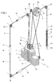
Figure 1 is a perspective view of a first example embodiment of the exercise machine in accordance with the invention; -
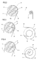
Figure 2 is a side elevation view of a detail of the machine ofFigure 1 ; -
Figure 3 is a side elevation view of a detail of a second example embodiment of the exercise machine in accordance with the invention; -
Figure 4 is a side elevation view of a detail of a third example embodiment of the exercise machine in accordance with the invention. - With reference to the accompanying drawings, and in particular with reference to
Figure 1 , the numeral 1 denotes an exercise machine in accordance with the invention, which can be used to perform exercises for developing motor abilities and muscular strength. The machine 1 has aframe 2, for the sake of simplicity only partly represented in the drawings, which supports a plurality ofpulleys - To simplify the description, reference will be made to the case in which the axes of rotation of the pulleys are fixed relative to the frame. However, it must be remembered that the description which follows may also be extended to the case in which the pulleys are connected to the frame by means of respective supports rotating according to axes transversal to the axis of rotation of the pulleys themselves, as described in the above-mentioned patent, thus allowing the user to operate the grip element performing movements which are free in space. Moreover, the machine 1 comprises a
flexible cable 4 wound on the plurality ofpulleys consecutive pulleys vertical operating segment 4a for thecable 4, between thepulleys consecutive pulleys frame 2 and horizontally aligned, so as to form ahorizontal operating segment cable 4, respectively between thepulleys - The machine 1 comprises at least one
grip element 5a connected to thecable 4 along the operating segments described above, designed to be operated by a user in order to perform exercises. Thegrip element 5a slides freely and can be selectively rigidly connected to thecable 4. In particular, thegrip element 5a comprises acylindrical element 6 having an axial cavity through which thecable 4 passes in a selectively sliding fashion. - Moreover, the machine 1 comprises a resistant load, labelled 7 as a whole, supported by the
frame 2 in such a way that it can slide freely and connected to theflexible cable 4 by means of theidle pulleys - In particular, the
resistant load 7 is gravitational, with adjustable intensity, of the weight stack-style known type. In such types of resistant load, a plurality ofplates 9 is supported by theframe 2 in such a way that they slide freely along a substantially verticalstraight guide 10. The machine 1 comprises abracket 11 rigidly fixed on thefirst plate 9a, at the top of theresistant load 7. Theidle pulleys 8 are rotatably supported on thebracket 11. The exercise machine also comprises acylindrical bar 12, integral with the bottom of thebracket 11, having a set of holes not illustrated in the drawing arranged transversally along its axis, the bar engaging in achannel 12a formed by central holes made in each of theplates 9. Eachplate 9 has a hole communicating with thechannel 12a, opposite and aligned with a respective hole in thebar 12, not illustrated in the drawing. There is also a selectingpin 13 designed to be inserted in one of the holes in thecylindrical bar 12 and in thecorresponding plate 9 so as to connect the desired number ofplates 9, and therefore the desiredresistant load 7, to thecable 4. Advantageously, the machine 1 comprises areturn device 14 to which a first end and a second end 4' and 4'' of thecable 4 are fixed. Saidreturn device 14 comprises adrum 15 rotatably supported by theframe 2, on a preferablyhorizontal axis 15a, around which a first end portion of thecable 4 comprising the first end 4' is wound in a first winding direction, and a second end portion of thecable 4 comprising thesecond end 4" is wound in a second winding direction which is opposite to the previous winding direction. Theends 4' and 4" are fixed to thedrum 15 in a known way. For example, thedrum 15 has two radial cylindrical cavities designed to house respectively the first and the second end 4', 4'' which are fixed to thedrum 15 by corresponding fixing pins not illustrated in the accompanying drawings. Advantageously, thereturn device 14 comprises anelastic element 16 between thedrum 15 and theframe 2, designed to return thecable 4 to a configuration which shall be defined as the "initial configuration", at the end of any exercise involving operation of thegrip element 5a. Advantageously, theelastic element 16 is aspring 17 with afirst end 18 integral with theframe 2 and asecond end 19 integral with thedrum 15. Preferably, with reference toFigure 1 , saidspring 17 is of the cylindrical helical extension type, whilst thefirst end 18 and thesecond end 19 consist of two fixing eyelets. Thefirst end 18 is fixed to theframe 2 by acorresponding ring 18a. Thereturn device 14 also comprises a secondary connectingcable 20 between thedrum 15 and thespring 17. In particular, thedrum 15 has aradial seat 21, formed byflared surfaces 21a, designed to rigidly house afirst end 22 of thesecondary cable 4, whilst thesecond end 23 of the latter is connected to thesecond end 19 of the spring 17 (Figure 2 ). Thesecondary cable 20 is wound around asecondary pulley 24 rotatably mounted on theframe 2 in such a way that it rotates relative to a preferably horizontal axis and is such that it causes thespring 17 to apply its return action in a vertical direction. Preferably, as illustrated inFigure 1 , the exercise machine 1 comprises threegrip elements cable 4, there being an upperhorizontal segment 4c relative to theresistant load 7, avertical segment 4a and a lowerhorizontal segment 4b relative to theresistant load 7. Obviously, the consecutive pulleys which delimit the vertical operating segment will be the same as those delimiting an end of the two horizontal segments. - For completeness, the following is a description of the path of the
cable 4 in a preferred embodiment of the machine 1, in accordance with the present invention, considering the machine in the initial configuration, that is to say, before the exercise is performed, or at the end of performance of the exercise. Starting from the first end 4' of thecable 4 fixed to thedrum 15, the first end portion is wound around thedrum 15. Thecable 4 then passes around theidle pulley 8, integral with theresistant load 7, after which it passes around thepulleys cable 4 passes around theidle pulleys second end 4" of the cable is wound around and secured on thedrum 15.Figures 3 and 4 show further embodiments of thereturn device 14. As can be seen, for simplicity elements which also appear in the first embodiment described above with reference toFigure 1 are labelled with the same reference characters. Appropriately, thereturn device 14 comprises aspring 17 of the cylindrical helical torsion type, or of the spiral type. In these two embodiments, thereturn device 14 also comprises asecondary drum 25 supported on theframe 2 in such a way that it rotates relative to a preferably horizontal axis. Thesecondary cable 20 has afirst end 22 fixed to thedrum 15 in a respectiveradial seat 21 and has an end portion 23', ending with thesecond end 23, wound around thesecondary drum 25 to which thesecond end 23 is fixed. Thespring 17 comprises a first and a second end, respectively labelled 18 and 19, which delimit its circumferential development. Thefirst end 18 is rigidly fixed to theframe 2 whilst thesecond end 19 is fixed so that it is integral with thesecondary drum 25, in such a way that thespring 17 applies a return action for thesecondary drum 25 in the circumferential direction according to an axis substantially coinciding with the axis of the secondary drum, consequently returning thereturn device 14 to the initial configuration by means of thesecondary cable 20. Thespring 17 applies the return action according to a predetermined direction of rotation which depends on the direction with which thesecondary cable 20 is wound relative to thesecondary drum 25. Operation of the exercise machine 1 in accordance with the invention is intuitive and is described briefly below. - While performing the exercise, the user moves the
grip element 5a located at one of thecable 4 operating segments, the upperhorizontal segment 4c, the lowerhorizontal segment 4b or thevertical segment 4a, according to the muscles to be trained. In any case, the user's action on thecable 4 changes the machine 1 configuration relative to the initial configuration described above. In particular, the length of the selected cable operating segment is increased, consequently lifting theresistant load 7. Moreover, the length of one of the end portions of the cable wound around thedrum 15 is increased, with a simultaneous reduction in the length of the other end portion, wound around thedrum 15 in the opposite direction, withconsequent drum 15 rotation about its own axis.Drum 15 rotation in one direction rather than another depends on the type of exercise the user performs. For example, thedrum 15 direction of rotation associated with user action on thegrip element 5c of the upperhorizontal operating segment 4c of thecable 4 is opposite to that associated with user action on thegrip element 5b of the lowerhorizontal operating segment 4b. - Appropriately, with reference to
Figure 1 , drum 15 rotation generates, by means of thesecondary cable 20, thespring 17 return action which tends to return thedrum 15 itself to the initial configuration at the end of the exercise. In particular, thesecondary cable 20 pulls the cylindricalhelical extension spring 17. The presence of the flaredsurfaces 21a at theradial seat 21 allowsdrum 15 rotation, in one direction or the other even with considerable angles, without any risk of bending thesecondary cable 20 with small bending radii, and therefore without any risk of damaging or breaking it. Alternatively, in the other embodiments of thereturn device 14 shown inFigures 3 and 4 , thesecondary cable 20 causes the return action of the cylindricalhelical torsion spring 17 or the spiral spring by means ofsecondary drum 25 rotation about its own axis. - To clarify further, the length of the first and second end portions of the
cable 4 wound on the drum in the initial configuration limits the extent of the movement of thegrip element 5a which the user can perform. Obviously, the longer said length is, the greater the extent of movement of thegrip element 5a and consequently the movement by the user will be. - It should be added that if the user moves the
grip element 5a of thevertical operating segment 4a in a horizontal plane, starting from the middle of said segment, due tocable 4 symmetry said movement does not cause thedrum 15 to rotate and therefore does not cause a reaction by thespring 17 but instead simply causes theresistant load 7 to be lifted and lowered. As soon as the user brings thegrip element 5a out of said horizontal plane, lifting or lowering thegrip element 5a itself, thecable 4 causes thedrum 15 to rotate. Therefore, as indicated the invention achieves the preset aims. - In particular, the exercise machine 1 disclosed returns to the initial configuration after each use and therefore it is in the same configuration each time the user begins exercising, maintaining the same behaviour for all training. This result is made possible by the
return device 14 to which thecable 4 joint is suitably connected by fixing theends 4' and 4". Moreover, the invention allows the cable joint to be made in a simple and rapid way. In addition to that, the exercise machine disclosed involves limited and rapid operations for its production. - The invention described above may be modified and adapted in several ways without thereby departing from the scope of the inventive concept.
- The invention described above is susceptible of industrial application and may be modified and adapted in many other ways without thereby departing from the scope of the inventive concept. Moreover, all details of the invention may be substituted by technically equivalent elements without departing from the protective scope of the claims herein.
Claims (23)
- An exercise machine (1) for developing motor abilities and muscular strength, of the type comprising at least one supporting frame (2), at least one flexible cable (4) wound on a plurality of pulleys (3a, 3b, 3c, 3d) rotatably supported by the frame (2) and connected to at least one resistant load (7), at least one grip element (5a; 5b; 5c) connected to the cable (4) and designed to be operated by a user in order to perform an exercise, the machine being characterised in that it comprises at least one return device (14), to which the ends (4', 4") of the cable (4) are connected, said return device designed to return the cable (4) to the initial configuration after an exercise has been performed.
- The exercise machine according to claim 1, characterised in that the return device (14) comprises at least one drum (15), rotatably supported by the frame (2), around which a first end portion of the cable (4) is wound in a first winding direction.
- The exercise machine according to claim 2, characterised in that the cable (4) comprises a second end portion wound around the drum (15) in a second winding direction which is opposite to the first winding direction.
- The exercise machine according to any of the foregoing claims, characterised in that the return device (14) comprises at least one elastic element (16) between the frame (2) and the drum (15) designed to return the drum (15) to the initial configuration after an exercise has been performed.
- The exercise machine according to the foregoing claim, characterised in that the elastic element (16) comprises a first end (18) integral with the frame (2) and a second end (19) connected to the drum (15).
- The exercise machine according to the foregoing claim, characterised in that the return device (14) comprises at least one secondary cable (20), designed to connect the elastic element (16) to the drum (15); the secondary cable (20) comprising a first end (22) rigidly connected to the drum (15).
- The exercise machine according to the foregoing claim, characterised in that the drum (15) comprises a radial seat (21) designed to rigidly house the first end (22).
- The exercise machine according to claim 7, characterised in that the radial seat (21) is formed by flared surfaces (21a).
- The exercise machine according to claims 4 to 8, characterised in that the elastic element (16) comprises at least one spring (17).
- The exercise machine according to the foregoing claim, characterised in that the spring (17) is of the cylindrical helical extension type; the secondary cable (20) comprising a second end (23) rigidly connected to the second end (19) of the elastic element.
- The exercise machine according to claim 10, characterised in that the return device (14) comprises at least one secondary pulley (24) rotatably supported by the frame (2) and designed to have the secondary cable (20) wound around it.
- The exercise machine according to claim 9, characterised in that the return device (14) comprises at least one secondary drum (25) rotatably supported by the frame (2); the secondary cable (20) comprising a second end (23) rigidly connected to the secondary drum (25) and an end portion (23') ending with said second end (23), wound around the secondary drum (25) in a predetermined winding direction.
- The exercise machine according to the foregoing claim, characterised in that the spring (17) is of the cylindrical helical torsion type or of the spiral type; the second end (23) being integral with the secondary drum (25).
- The exercise machine according to any of the foregoing claims, characterised in that the resistant load (7) is of the gravitational type.
- The exercise machine according to claim 14, characterised in that the resistant load (7) comprises a plurality of plates (9) supported by the frame (2) in such a way that they can slide freely along a substantially vertical straight guide (10), and a selection pin (13) designed to connect at least one plate of said plurality of plates (9) to the cable (4).
- The exercise machine according to any of the foregoing claims, characterised in that the grip element (5a, 5b, 5c) is connected to the cable (4) in such a way that it can slide freely.
- The exercise machine according to any of the foregoing claims, characterised in that the grip element (5a, 5b, 5c) is designed to be selectively rigidly connected to the cable (4).
- The exercise machine according to any of the foregoing claims, characterised in that the grip element (5a, 5b, 5c) is designed to integrally connect to the cable (4) while the exercise is being performed.
- The exercise machine according to any of the foregoing claims, characterised in that the grip element (5a, 5b, 5c) comprises a cylindrical element (6) having an axial cavity through which the cable (4) passes in a selectively sliding fashion.
- The exercise machine according to any of the foregoing claims, characterised in that it comprises a first and a second pulley (3c, 3a; 3a, 3b; 3b, 3d) supported by the frame (2) in such a way that they can rotate according to respective parallel axes, being designed to form a first operating segment (4c; 4a; 4b) of the cable (4), between the first and second pulleys (3c, 3a; 3a, 3b; 3b, 3d), along a direction substantially at a right angle to said axes; the grip element (5a, 5b, 5c) being able to move along the first operating segment (4c; 4a; 4b).
- The exercise machine according to claim 18, characterised in that the first operating segment (4c; 4a; 4b) is vertical.
- The exercise machine according to claim 18, characterised in that the first operating segment (4c; 4a; 4b) is horizontal.
- The exercise machine according to any of the foregoing claims, characterised in that it comprises three grip elements (5a, 5b, 5c), respectively connected to said operating segments (4a, 4b, 4c).
Applications Claiming Priority (1)
| Application Number | Priority Date | Filing Date | Title |
|---|---|---|---|
| IT000126A ITBO20080126A1 (en) | 2008-02-27 | 2008-02-27 | GINNICA MACHINE. |
Publications (2)
| Publication Number | Publication Date |
|---|---|
| EP2095849A1 true EP2095849A1 (en) | 2009-09-02 |
| EP2095849B1 EP2095849B1 (en) | 2014-12-24 |
Family
ID=40291447
Family Applications (1)
| Application Number | Title | Priority Date | Filing Date |
|---|---|---|---|
| EP09153663.1A Not-in-force EP2095849B1 (en) | 2008-02-27 | 2009-02-25 | Exercise machine |
Country Status (3)
| Country | Link |
|---|---|
| US (1) | US8016730B2 (en) |
| EP (1) | EP2095849B1 (en) |
| IT (1) | ITBO20080126A1 (en) |
Cited By (1)
| Publication number | Priority date | Publication date | Assignee | Title |
|---|---|---|---|---|
| EP4356982A1 (en) * | 2022-10-21 | 2024-04-24 | Yangzhou Jiuyi Hardware & Machinery Co., Ltd. | Fitness exercise apparatus |
Families Citing this family (6)
| Publication number | Priority date | Publication date | Assignee | Title |
|---|---|---|---|---|
| US20120108402A1 (en) * | 2010-02-03 | 2012-05-03 | Rodgers Jr Robert E | Exercise Apparatus With an Inertia System |
| KR101125736B1 (en) * | 2011-12-14 | 2012-03-27 | (주)개선스포츠 | Weight exercise equipment for generating exercise load only in the direction of movement |
| US10220235B2 (en) * | 2012-05-21 | 2019-03-05 | Joshua Norris | Controlled motion exercise device |
| US9415257B2 (en) | 2012-06-18 | 2016-08-16 | Douglas John Habing | Hybrid resistance system |
| US9802075B2 (en) * | 2013-05-03 | 2017-10-31 | Gvoich Fitness Systems | Dual balance exercise apparatus |
| US20200069993A1 (en) | 2016-12-07 | 2020-03-05 | Egym Gmbh | Exercising device |
Citations (3)
| Publication number | Priority date | Publication date | Assignee | Title |
|---|---|---|---|---|
| US4603855A (en) * | 1981-01-02 | 1986-08-05 | Sebelle Leslie W | Variable exercise apparatus |
| EP1402925A1 (en) * | 2002-09-30 | 2004-03-31 | TECHNOGYM S.p.A. | Exercising machine |
| EP1790390A1 (en) | 2005-11-25 | 2007-05-30 | TECHNOGYM S.p.A. | Gymnastic machine |
Family Cites Families (16)
| Publication number | Priority date | Publication date | Assignee | Title |
|---|---|---|---|---|
| US5380258A (en) * | 1992-10-26 | 1995-01-10 | Stairmaster Sports/Medical Products, Inc. | Exercise apparatus |
| WO1994027680A1 (en) * | 1993-06-02 | 1994-12-08 | Ehrenfried Ted R | Aerobic strength apparatus |
| US5354251A (en) * | 1993-11-01 | 1994-10-11 | Sleamaker Robert H | Multifunction excercise machine with ergometric input-responsive resistance |
| US5366426A (en) * | 1993-11-05 | 1994-11-22 | Glavin James P | Swimming exerciser with improved leg motion |
| US5624362A (en) * | 1993-12-29 | 1997-04-29 | Wilson; Thomas I. | Punching handle accessory |
| US5928117A (en) * | 1996-10-11 | 1999-07-27 | Vittone; Larry W. | Motion-resisting exercise apparatus utilizing concentric frames |
| US6004244A (en) * | 1997-02-13 | 1999-12-21 | Cybex International, Inc. | Simulated hill-climbing exercise apparatus and method of exercising |
| US6283899B1 (en) * | 1997-07-24 | 2001-09-04 | Richard D. Charnitski | Inertial resistance exercise apparatus and method |
| US6261208B1 (en) * | 1999-05-13 | 2001-07-17 | Murdock Carson, Jr. | Rope pulling frictional exercise device |
| US6394935B1 (en) * | 1999-09-03 | 2002-05-28 | Intra-Med Industries, Inc. | Therapeutic exercise apparatus |
| US20030153441A1 (en) * | 2001-10-26 | 2003-08-14 | Jeffrey Berns | Platform-based cable exercise device and method |
| US7086991B2 (en) * | 2002-07-19 | 2006-08-08 | Michael Edward Williams | Rope climbing simulator |
| US7014599B2 (en) * | 2003-05-07 | 2006-03-21 | Peter Ashley | Selectable force exercise machine |
| US7553262B2 (en) * | 2004-11-12 | 2009-06-30 | Bvp Holding, Inc. | Exercise apparatus using weights and springs for high-speed training |
| ATE467444T1 (en) * | 2005-03-01 | 2010-05-15 | Technogym Spa | GYMNASTICS EQUIPMENT AND CONNECTED HANDLE ELEMENT |
| US7789812B2 (en) * | 2008-09-30 | 2010-09-07 | Joseph M. Anderson | Rope climbing exercise apparatus |
-
2008
- 2008-02-27 IT IT000126A patent/ITBO20080126A1/en unknown
-
2009
- 2009-02-25 EP EP09153663.1A patent/EP2095849B1/en not_active Not-in-force
- 2009-02-25 US US12/392,696 patent/US8016730B2/en active Active
Patent Citations (4)
| Publication number | Priority date | Publication date | Assignee | Title |
|---|---|---|---|---|
| US4603855A (en) * | 1981-01-02 | 1986-08-05 | Sebelle Leslie W | Variable exercise apparatus |
| EP1402925A1 (en) * | 2002-09-30 | 2004-03-31 | TECHNOGYM S.p.A. | Exercising machine |
| EP1402925B1 (en) | 2002-09-30 | 2006-12-06 | TECHNOGYM S.p.A. | Exercising machine |
| EP1790390A1 (en) | 2005-11-25 | 2007-05-30 | TECHNOGYM S.p.A. | Gymnastic machine |
Cited By (1)
| Publication number | Priority date | Publication date | Assignee | Title |
|---|---|---|---|---|
| EP4356982A1 (en) * | 2022-10-21 | 2024-04-24 | Yangzhou Jiuyi Hardware & Machinery Co., Ltd. | Fitness exercise apparatus |
Also Published As
| Publication number | Publication date |
|---|---|
| US8016730B2 (en) | 2011-09-13 |
| ITBO20080126A1 (en) | 2009-08-28 |
| US20090215591A1 (en) | 2009-08-27 |
| EP2095849B1 (en) | 2014-12-24 |
Similar Documents
| Publication | Publication Date | Title |
|---|---|---|
| EP2095849B1 (en) | Exercise machine | |
| US6770015B2 (en) | Exercise apparatus with sliding pulley | |
| EP2326393B1 (en) | Continuous rope pulling exercise apparatus | |
| US9211440B2 (en) | Adjustable exercise system | |
| RU2500448C2 (en) | Simulator having flexible element | |
| US7927262B2 (en) | Compact multi-function exercise apparatus | |
| US9486660B2 (en) | Flat row exercise machine | |
| KR101425769B1 (en) | Motorized weight-training device and method of controlling the same | |
| EP0368591A2 (en) | Variable resistance weight lifting exercise apparatus | |
| US20110098155A1 (en) | Tension Systems and Methods of Use | |
| CN106730592B (en) | Rowing machine | |
| US20140141946A1 (en) | Exercise device using undulation members | |
| CN108697920A (en) | Exercising apparatus with the pairing of non-matching cable | |
| US20070004526A1 (en) | Golf Exercising Method | |
| WO2009089131A1 (en) | Rowing trainer | |
| JPH0349774A (en) | Variable force-resister type gymnastic apparatus | |
| KR101875512B1 (en) | Weight Training Equipment with Adjustable Handle Angle | |
| US4753437A (en) | Weightlifting exercise device | |
| JP2009509628A (en) | Strength training and rehabilitation training machine | |
| EP1928562B1 (en) | Training machine for strengthen training and rehabilitation | |
| ITBO960325A1 (en) | VARIABLE STRUCTURE GYMNUM MACHINE | |
| ITBO970427A1 (en) | GYMNASIAN MACHINE WITH STRUCTURE ADJUSTMENT. | |
| KR101893362B1 (en) | Posture correction device for exercise | |
| EP2095851A1 (en) | Grip element for exercise machine | |
| KR101348317B1 (en) | A Wave-type Training Device |
Legal Events
| Date | Code | Title | Description |
|---|---|---|---|
| PUAI | Public reference made under article 153(3) epc to a published international application that has entered the european phase |
Free format text: ORIGINAL CODE: 0009012 |
|
| AK | Designated contracting states |
Kind code of ref document: A1 Designated state(s): AT BE BG CH CY CZ DE DK EE ES FI FR GB GR HR HU IE IS IT LI LT LU LV MC MK MT NL NO PL PT RO SE SI SK TR |
|
| AX | Request for extension of the european patent |
Extension state: AL BA RS |
|
| 17P | Request for examination filed |
Effective date: 20100302 |
|
| AKX | Designation fees paid |
Designated state(s): AT BE BG CH CY CZ DE DK EE ES FI FR GB GR HR HU IE IS IT LI LT LU LV MC MK MT NL NO PL PT RO SE SI SK TR |
|
| GRAP | Despatch of communication of intention to grant a patent |
Free format text: ORIGINAL CODE: EPIDOSNIGR1 |
|
| INTG | Intention to grant announced |
Effective date: 20140725 |
|
| GRAS | Grant fee paid |
Free format text: ORIGINAL CODE: EPIDOSNIGR3 |
|
| GRAA | (expected) grant |
Free format text: ORIGINAL CODE: 0009210 |
|
| AK | Designated contracting states |
Kind code of ref document: B1 Designated state(s): AT BE BG CH CY CZ DE DK EE ES FI FR GB GR HR HU IE IS IT LI LT LU LV MC MK MT NL NO PL PT RO SE SI SK TR |
|
| REG | Reference to a national code |
Ref country code: GB Ref legal event code: FG4D |
|
| REG | Reference to a national code |
Ref country code: CH Ref legal event code: EP |
|
| REG | Reference to a national code |
Ref country code: IE Ref legal event code: FG4D |
|
| REG | Reference to a national code |
Ref country code: AT Ref legal event code: REF Ref document number: 702833 Country of ref document: AT Kind code of ref document: T Effective date: 20150115 |
|
| REG | Reference to a national code |
Ref country code: DE Ref legal event code: R096 Ref document number: 602009028507 Country of ref document: DE Effective date: 20150212 |
|
| REG | Reference to a national code |
Ref country code: NL Ref legal event code: VDEP Effective date: 20141224 |
|
| PG25 | Lapsed in a contracting state [announced via postgrant information from national office to epo] |
Ref country code: LT Free format text: LAPSE BECAUSE OF FAILURE TO SUBMIT A TRANSLATION OF THE DESCRIPTION OR TO PAY THE FEE WITHIN THE PRESCRIBED TIME-LIMIT Effective date: 20141224 Ref country code: FI Free format text: LAPSE BECAUSE OF FAILURE TO SUBMIT A TRANSLATION OF THE DESCRIPTION OR TO PAY THE FEE WITHIN THE PRESCRIBED TIME-LIMIT Effective date: 20141224 Ref country code: NO Free format text: LAPSE BECAUSE OF FAILURE TO SUBMIT A TRANSLATION OF THE DESCRIPTION OR TO PAY THE FEE WITHIN THE PRESCRIBED TIME-LIMIT Effective date: 20150324 |
|
| REG | Reference to a national code |
Ref country code: LT Ref legal event code: MG4D |
|
| PG25 | Lapsed in a contracting state [announced via postgrant information from national office to epo] |
Ref country code: LV Free format text: LAPSE BECAUSE OF FAILURE TO SUBMIT A TRANSLATION OF THE DESCRIPTION OR TO PAY THE FEE WITHIN THE PRESCRIBED TIME-LIMIT Effective date: 20141224 Ref country code: HR Free format text: LAPSE BECAUSE OF FAILURE TO SUBMIT A TRANSLATION OF THE DESCRIPTION OR TO PAY THE FEE WITHIN THE PRESCRIBED TIME-LIMIT Effective date: 20141224 Ref country code: SE Free format text: LAPSE BECAUSE OF FAILURE TO SUBMIT A TRANSLATION OF THE DESCRIPTION OR TO PAY THE FEE WITHIN THE PRESCRIBED TIME-LIMIT Effective date: 20141224 Ref country code: GR Free format text: LAPSE BECAUSE OF FAILURE TO SUBMIT A TRANSLATION OF THE DESCRIPTION OR TO PAY THE FEE WITHIN THE PRESCRIBED TIME-LIMIT Effective date: 20150325 |
|
| REG | Reference to a national code |
Ref country code: AT Ref legal event code: MK05 Ref document number: 702833 Country of ref document: AT Kind code of ref document: T Effective date: 20141224 |
|
| PG25 | Lapsed in a contracting state [announced via postgrant information from national office to epo] |
Ref country code: NL Free format text: LAPSE BECAUSE OF FAILURE TO SUBMIT A TRANSLATION OF THE DESCRIPTION OR TO PAY THE FEE WITHIN THE PRESCRIBED TIME-LIMIT Effective date: 20141224 |
|
| PG25 | Lapsed in a contracting state [announced via postgrant information from national office to epo] |
Ref country code: SK Free format text: LAPSE BECAUSE OF FAILURE TO SUBMIT A TRANSLATION OF THE DESCRIPTION OR TO PAY THE FEE WITHIN THE PRESCRIBED TIME-LIMIT Effective date: 20141224 Ref country code: RO Free format text: LAPSE BECAUSE OF FAILURE TO SUBMIT A TRANSLATION OF THE DESCRIPTION OR TO PAY THE FEE WITHIN THE PRESCRIBED TIME-LIMIT Effective date: 20141224 Ref country code: ES Free format text: LAPSE BECAUSE OF FAILURE TO SUBMIT A TRANSLATION OF THE DESCRIPTION OR TO PAY THE FEE WITHIN THE PRESCRIBED TIME-LIMIT Effective date: 20141224 Ref country code: EE Free format text: LAPSE BECAUSE OF FAILURE TO SUBMIT A TRANSLATION OF THE DESCRIPTION OR TO PAY THE FEE WITHIN THE PRESCRIBED TIME-LIMIT Effective date: 20141224 Ref country code: CZ Free format text: LAPSE BECAUSE OF FAILURE TO SUBMIT A TRANSLATION OF THE DESCRIPTION OR TO PAY THE FEE WITHIN THE PRESCRIBED TIME-LIMIT Effective date: 20141224 |
|
| PG25 | Lapsed in a contracting state [announced via postgrant information from national office to epo] |
Ref country code: AT Free format text: LAPSE BECAUSE OF FAILURE TO SUBMIT A TRANSLATION OF THE DESCRIPTION OR TO PAY THE FEE WITHIN THE PRESCRIBED TIME-LIMIT Effective date: 20141224 Ref country code: IS Free format text: LAPSE BECAUSE OF FAILURE TO SUBMIT A TRANSLATION OF THE DESCRIPTION OR TO PAY THE FEE WITHIN THE PRESCRIBED TIME-LIMIT Effective date: 20150424 Ref country code: PL Free format text: LAPSE BECAUSE OF FAILURE TO SUBMIT A TRANSLATION OF THE DESCRIPTION OR TO PAY THE FEE WITHIN THE PRESCRIBED TIME-LIMIT Effective date: 20141224 |
|
| REG | Reference to a national code |
Ref country code: DE Ref legal event code: R097 Ref document number: 602009028507 Country of ref document: DE |
|
| PG25 | Lapsed in a contracting state [announced via postgrant information from national office to epo] |
Ref country code: LU Free format text: LAPSE BECAUSE OF FAILURE TO SUBMIT A TRANSLATION OF THE DESCRIPTION OR TO PAY THE FEE WITHIN THE PRESCRIBED TIME-LIMIT Effective date: 20150225 |
|
| REG | Reference to a national code |
Ref country code: CH Ref legal event code: PL |
|
| PG25 | Lapsed in a contracting state [announced via postgrant information from national office to epo] |
Ref country code: CH Free format text: LAPSE BECAUSE OF NON-PAYMENT OF DUE FEES Effective date: 20150228 Ref country code: MC Free format text: LAPSE BECAUSE OF FAILURE TO SUBMIT A TRANSLATION OF THE DESCRIPTION OR TO PAY THE FEE WITHIN THE PRESCRIBED TIME-LIMIT Effective date: 20141224 Ref country code: LI Free format text: LAPSE BECAUSE OF NON-PAYMENT OF DUE FEES Effective date: 20150228 Ref country code: DK Free format text: LAPSE BECAUSE OF FAILURE TO SUBMIT A TRANSLATION OF THE DESCRIPTION OR TO PAY THE FEE WITHIN THE PRESCRIBED TIME-LIMIT Effective date: 20141224 |
|
| PLBE | No opposition filed within time limit |
Free format text: ORIGINAL CODE: 0009261 |
|
| STAA | Information on the status of an ep patent application or granted ep patent |
Free format text: STATUS: NO OPPOSITION FILED WITHIN TIME LIMIT |
|
| REG | Reference to a national code |
Ref country code: IE Ref legal event code: MM4A |
|
| 26N | No opposition filed |
Effective date: 20150925 |
|
| PG25 | Lapsed in a contracting state [announced via postgrant information from national office to epo] |
Ref country code: IE Free format text: LAPSE BECAUSE OF NON-PAYMENT OF DUE FEES Effective date: 20150225 |
|
| REG | Reference to a national code |
Ref country code: FR Ref legal event code: PLFP Year of fee payment: 8 |
|
| PG25 | Lapsed in a contracting state [announced via postgrant information from national office to epo] |
Ref country code: SI Free format text: LAPSE BECAUSE OF FAILURE TO SUBMIT A TRANSLATION OF THE DESCRIPTION OR TO PAY THE FEE WITHIN THE PRESCRIBED TIME-LIMIT Effective date: 20141224 |
|
| PG25 | Lapsed in a contracting state [announced via postgrant information from national office to epo] |
Ref country code: BE Free format text: LAPSE BECAUSE OF FAILURE TO SUBMIT A TRANSLATION OF THE DESCRIPTION OR TO PAY THE FEE WITHIN THE PRESCRIBED TIME-LIMIT Effective date: 20141224 |
|
| PG25 | Lapsed in a contracting state [announced via postgrant information from national office to epo] |
Ref country code: MT Free format text: LAPSE BECAUSE OF FAILURE TO SUBMIT A TRANSLATION OF THE DESCRIPTION OR TO PAY THE FEE WITHIN THE PRESCRIBED TIME-LIMIT Effective date: 20141224 |
|
| REG | Reference to a national code |
Ref country code: FR Ref legal event code: PLFP Year of fee payment: 9 |
|
| PG25 | Lapsed in a contracting state [announced via postgrant information from national office to epo] |
Ref country code: BG Free format text: LAPSE BECAUSE OF FAILURE TO SUBMIT A TRANSLATION OF THE DESCRIPTION OR TO PAY THE FEE WITHIN THE PRESCRIBED TIME-LIMIT Effective date: 20141224 Ref country code: HU Free format text: LAPSE BECAUSE OF FAILURE TO SUBMIT A TRANSLATION OF THE DESCRIPTION OR TO PAY THE FEE WITHIN THE PRESCRIBED TIME-LIMIT; INVALID AB INITIO Effective date: 20090225 |
|
| PG25 | Lapsed in a contracting state [announced via postgrant information from national office to epo] |
Ref country code: CY Free format text: LAPSE BECAUSE OF FAILURE TO SUBMIT A TRANSLATION OF THE DESCRIPTION OR TO PAY THE FEE WITHIN THE PRESCRIBED TIME-LIMIT Effective date: 20141224 |
|
| PG25 | Lapsed in a contracting state [announced via postgrant information from national office to epo] |
Ref country code: PT Free format text: LAPSE BECAUSE OF FAILURE TO SUBMIT A TRANSLATION OF THE DESCRIPTION OR TO PAY THE FEE WITHIN THE PRESCRIBED TIME-LIMIT Effective date: 20150424 |
|
| PG25 | Lapsed in a contracting state [announced via postgrant information from national office to epo] |
Ref country code: TR Free format text: LAPSE BECAUSE OF FAILURE TO SUBMIT A TRANSLATION OF THE DESCRIPTION OR TO PAY THE FEE WITHIN THE PRESCRIBED TIME-LIMIT Effective date: 20141224 |
|
| REG | Reference to a national code |
Ref country code: FR Ref legal event code: PLFP Year of fee payment: 10 |
|
| PG25 | Lapsed in a contracting state [announced via postgrant information from national office to epo] |
Ref country code: MK Free format text: LAPSE BECAUSE OF FAILURE TO SUBMIT A TRANSLATION OF THE DESCRIPTION OR TO PAY THE FEE WITHIN THE PRESCRIBED TIME-LIMIT Effective date: 20141224 |
|
| PGFP | Annual fee paid to national office [announced via postgrant information from national office to epo] |
Ref country code: GB Payment date: 20190227 Year of fee payment: 11 Ref country code: IT Payment date: 20190221 Year of fee payment: 11 |
|
| PGFP | Annual fee paid to national office [announced via postgrant information from national office to epo] |
Ref country code: FR Payment date: 20190226 Year of fee payment: 11 |
|
| PGFP | Annual fee paid to national office [announced via postgrant information from national office to epo] |
Ref country code: DE Payment date: 20190430 Year of fee payment: 11 |
|
| REG | Reference to a national code |
Ref country code: DE Ref legal event code: R119 Ref document number: 602009028507 Country of ref document: DE |
|
| GBPC | Gb: european patent ceased through non-payment of renewal fee |
Effective date: 20200225 |
|
| PG25 | Lapsed in a contracting state [announced via postgrant information from national office to epo] |
Ref country code: GB Free format text: LAPSE BECAUSE OF NON-PAYMENT OF DUE FEES Effective date: 20200225 Ref country code: DE Free format text: LAPSE BECAUSE OF NON-PAYMENT OF DUE FEES Effective date: 20200901 Ref country code: FR Free format text: LAPSE BECAUSE OF NON-PAYMENT OF DUE FEES Effective date: 20200229 |
|
| PG25 | Lapsed in a contracting state [announced via postgrant information from national office to epo] |
Ref country code: IT Free format text: LAPSE BECAUSE OF NON-PAYMENT OF DUE FEES Effective date: 20200225 |