EP2094957B1 - Turbine heat shield assembly - Google Patents
Turbine heat shield assembly Download PDFInfo
- Publication number
- EP2094957B1 EP2094957B1 EP07854510.0A EP07854510A EP2094957B1 EP 2094957 B1 EP2094957 B1 EP 2094957B1 EP 07854510 A EP07854510 A EP 07854510A EP 2094957 B1 EP2094957 B1 EP 2094957B1
- Authority
- EP
- European Patent Office
- Prior art keywords
- heat shield
- bearing housing
- turbocharger
- connecting projection
- turbine
- Prior art date
- Legal status (The legal status is an assumption and is not a legal conclusion. Google has not performed a legal analysis and makes no representation as to the accuracy of the status listed.)
- Active
Links
- 238000000034 method Methods 0.000 claims description 23
- 230000006835 compression Effects 0.000 claims description 11
- 238000007906 compression Methods 0.000 claims description 11
- 239000000314 lubricant Substances 0.000 claims description 6
- 238000005461 lubrication Methods 0.000 claims description 5
- 238000004519 manufacturing process Methods 0.000 description 4
- 239000010687 lubricating oil Substances 0.000 description 3
- 239000003921 oil Substances 0.000 description 2
- 229910001018 Cast iron Inorganic materials 0.000 description 1
- 229910001060 Gray iron Inorganic materials 0.000 description 1
- 230000002411 adverse Effects 0.000 description 1
- 230000000712 assembly Effects 0.000 description 1
- 238000000429 assembly Methods 0.000 description 1
- 230000004888 barrier function Effects 0.000 description 1
- 230000015572 biosynthetic process Effects 0.000 description 1
- 238000002485 combustion reaction Methods 0.000 description 1
- 238000013461 design Methods 0.000 description 1
- 230000001627 detrimental effect Effects 0.000 description 1
- 230000006698 induction Effects 0.000 description 1
- 238000003780 insertion Methods 0.000 description 1
- 230000037431 insertion Effects 0.000 description 1
- 230000001050 lubricating effect Effects 0.000 description 1
- 239000002184 metal Substances 0.000 description 1
- 229910052751 metal Inorganic materials 0.000 description 1
- 238000012986 modification Methods 0.000 description 1
- 230000004048 modification Effects 0.000 description 1
- 230000003647 oxidation Effects 0.000 description 1
- 238000007254 oxidation reaction Methods 0.000 description 1
- 238000012546 transfer Methods 0.000 description 1
Images


Classifications
-
- F—MECHANICAL ENGINEERING; LIGHTING; HEATING; WEAPONS; BLASTING
- F02—COMBUSTION ENGINES; HOT-GAS OR COMBUSTION-PRODUCT ENGINE PLANTS
- F02B—INTERNAL-COMBUSTION PISTON ENGINES; COMBUSTION ENGINES IN GENERAL
- F02B39/00—Component parts, details, or accessories relating to, driven charging or scavenging pumps, not provided for in groups F02B33/00 - F02B37/00
- F02B39/14—Lubrication of pumps; Safety measures therefor
-
- F—MECHANICAL ENGINEERING; LIGHTING; HEATING; WEAPONS; BLASTING
- F01—MACHINES OR ENGINES IN GENERAL; ENGINE PLANTS IN GENERAL; STEAM ENGINES
- F01D—NON-POSITIVE DISPLACEMENT MACHINES OR ENGINES, e.g. STEAM TURBINES
- F01D25/00—Component parts, details, or accessories, not provided for in, or of interest apart from, other groups
- F01D25/16—Arrangement of bearings; Supporting or mounting bearings in casings
-
- F—MECHANICAL ENGINEERING; LIGHTING; HEATING; WEAPONS; BLASTING
- F01—MACHINES OR ENGINES IN GENERAL; ENGINE PLANTS IN GENERAL; STEAM ENGINES
- F01D—NON-POSITIVE DISPLACEMENT MACHINES OR ENGINES, e.g. STEAM TURBINES
- F01D25/00—Component parts, details, or accessories, not provided for in, or of interest apart from, other groups
- F01D25/24—Casings; Casing parts, e.g. diaphragms, casing fastenings
-
- F—MECHANICAL ENGINEERING; LIGHTING; HEATING; WEAPONS; BLASTING
- F02—COMBUSTION ENGINES; HOT-GAS OR COMBUSTION-PRODUCT ENGINE PLANTS
- F02B—INTERNAL-COMBUSTION PISTON ENGINES; COMBUSTION ENGINES IN GENERAL
- F02B39/00—Component parts, details, or accessories relating to, driven charging or scavenging pumps, not provided for in groups F02B33/00 - F02B37/00
-
- F—MECHANICAL ENGINEERING; LIGHTING; HEATING; WEAPONS; BLASTING
- F02—COMBUSTION ENGINES; HOT-GAS OR COMBUSTION-PRODUCT ENGINE PLANTS
- F02C—GAS-TURBINE PLANTS; AIR INTAKES FOR JET-PROPULSION PLANTS; CONTROLLING FUEL SUPPLY IN AIR-BREATHING JET-PROPULSION PLANTS
- F02C6/00—Plural gas-turbine plants; Combinations of gas-turbine plants with other apparatus; Adaptations of gas-turbine plants for special use
- F02C6/04—Gas-turbine plants providing heated or pressurised working fluid for other apparatus, e.g. without mechanical power output
- F02C6/10—Gas-turbine plants providing heated or pressurised working fluid for other apparatus, e.g. without mechanical power output supplying working fluid to a user, e.g. a chemical process, which returns working fluid to a turbine of the plant
- F02C6/12—Turbochargers, i.e. plants for augmenting mechanical power output of internal-combustion piston engines by increase of charge pressure
-
- F—MECHANICAL ENGINEERING; LIGHTING; HEATING; WEAPONS; BLASTING
- F05—INDEXING SCHEMES RELATING TO ENGINES OR PUMPS IN VARIOUS SUBCLASSES OF CLASSES F01-F04
- F05D—INDEXING SCHEME FOR ASPECTS RELATING TO NON-POSITIVE-DISPLACEMENT MACHINES OR ENGINES, GAS-TURBINES OR JET-PROPULSION PLANTS
- F05D2220/00—Application
- F05D2220/40—Application in turbochargers
-
- F—MECHANICAL ENGINEERING; LIGHTING; HEATING; WEAPONS; BLASTING
- F05—INDEXING SCHEMES RELATING TO ENGINES OR PUMPS IN VARIOUS SUBCLASSES OF CLASSES F01-F04
- F05D—INDEXING SCHEME FOR ASPECTS RELATING TO NON-POSITIVE-DISPLACEMENT MACHINES OR ENGINES, GAS-TURBINES OR JET-PROPULSION PLANTS
- F05D2230/00—Manufacture
- F05D2230/60—Assembly methods
-
- F—MECHANICAL ENGINEERING; LIGHTING; HEATING; WEAPONS; BLASTING
- F05—INDEXING SCHEMES RELATING TO ENGINES OR PUMPS IN VARIOUS SUBCLASSES OF CLASSES F01-F04
- F05D—INDEXING SCHEME FOR ASPECTS RELATING TO NON-POSITIVE-DISPLACEMENT MACHINES OR ENGINES, GAS-TURBINES OR JET-PROPULSION PLANTS
- F05D2260/00—Function
- F05D2260/20—Heat transfer, e.g. cooling
- F05D2260/231—Preventing heat transfer
-
- F—MECHANICAL ENGINEERING; LIGHTING; HEATING; WEAPONS; BLASTING
- F05—INDEXING SCHEMES RELATING TO ENGINES OR PUMPS IN VARIOUS SUBCLASSES OF CLASSES F01-F04
- F05D—INDEXING SCHEME FOR ASPECTS RELATING TO NON-POSITIVE-DISPLACEMENT MACHINES OR ENGINES, GAS-TURBINES OR JET-PROPULSION PLANTS
- F05D2260/00—Function
- F05D2260/30—Retaining components in desired mutual position
-
- Y—GENERAL TAGGING OF NEW TECHNOLOGICAL DEVELOPMENTS; GENERAL TAGGING OF CROSS-SECTIONAL TECHNOLOGIES SPANNING OVER SEVERAL SECTIONS OF THE IPC; TECHNICAL SUBJECTS COVERED BY FORMER USPC CROSS-REFERENCE ART COLLECTIONS [XRACs] AND DIGESTS
- Y10—TECHNICAL SUBJECTS COVERED BY FORMER USPC
- Y10T—TECHNICAL SUBJECTS COVERED BY FORMER US CLASSIFICATION
- Y10T29/00—Metal working
- Y10T29/49—Method of mechanical manufacture
- Y10T29/49316—Impeller making
- Y10T29/4932—Turbomachine making
Definitions
- This invention is directed to a turbocharging system for an internal combustion engine and more particularly to assembly of components of the turbocharger, according to the preamble part of claim 1.
- a turbo changer is known from US 2003/017 0117 A1 .
- Turbochargers are a type of forced induction system. They compress the air flowing into an engine, thus boosting the engine's horsepower without significantly increasing weight. Turbochargers use the exhaust flow from the engine to spin a turbine, which in turn drives an air compressor. Since the turbine spins about 30 times faster than most car engines and it is hooked up to the exhaust, the temperature in the turbine is very high. Additionally, due to the resulting high velocity of flow, turbochargers are subjected to noise and vibration. Such conditions can have a detrimental effect on the components of the turbocharger, particularly on the rotating parts such as the turbine rotor, which can lead to failure of the system. Additionally, thermal growth or expansion due to the temperature changes must be designed for which can lead to inefficiencies as a result of unwanted gaps under certain conditions.
- Turbochargers are in use in connection with large diesel engines as well as with smaller, passenger car power plants.
- the design and function of turbochargers is described in detail in the prior art, for example, U.S. Pat. Nos. 4,705,463 , 5,399,064 , and 6,164,931 , the disclosures of which are incorporated herein by reference.
- Turbocharger units typically include a turbine operatively connected to the engine exhaust manifold, a compressor operatively connected to the engine air intake manifold, and a shaft connecting the turbine wheel and compressor wheel so that the rapidly rotating turbine wheel drives the compressor wheel.
- the shaft extends through a bearing housing and is mounted for rotation in bearings.
- the bearings are most often free-floating bearings. Crankcase lubricant under pressure is pumped through the free floating bearings to lubricate the rotating bearing interfaces, as well as the thrust surfaces that limit axial excursions of the shaft.
- turbochargers In addition to performing the useful work as described above, turbochargers must be designed to combat two significant problems: first, oil should not be allowed to escape from the bearing housing into the turbine or compressor housing and from there into the environment, and the prior art, for example, U.S. Pat. Nos. 4,705,463 , 5,399,064 , and 6,164,931 , the disclosures of which are incorporated herein by reference.
- Turbocharger units typically include a turbine operatively connected to the engine exhaust manifold, a compressor operatively connected to the engine air intake manifold, and a shaft connecting the turbine wheel and compressor wheel so that the rapidly rotating turbine wheel drives the compressor wheel.
- the shaft extends through a bearing housing and is mounted for rotation in bearings.
- the bearings are most often free-floating bearings. Crankcase lubricant under pressure is pumped through the free floating bearings to lubricate the rotating bearing interfaces, as well as the thrust surfaces that limit axial excursions of the shaft.
- turbochargers In addition to performing the useful work as described above, turbochargers must be designed to combat two significant problems: first, oil should not be allowed to escape from the bearing housing into the turbine or compressor housing and from there into the environment, and second, the high temperature of the turbine must not be allowed to adversely affect the lubricating oil in the bearing housing.
- turbocharged vehicles are required to meet increasingly stringent emissions standards. It is a challenge to contain lubricant within the bearing housing, considering that lubricating oil is pumped in under pressure, at a high flow rate, to lubricate and remove heat from a turbine shaft which extends through the turbine housing and rotates at up to 350,000 rpm. Although barriers are set up in the turbocharger, some amount of the lubricant will escape from the bearing housing into either the turbine housing or the compressor housing. This lubricant is ultimately emitted into the environment via the exhaust, contributing to emissions.
- temperatures of about 740°C occur in the exhaust gas turbine in the case of diesel engines and about 1,000°C in the case of Otto-cycle engines.
- the transfer of high temperatures from the turbine portion of the turbocharger to the bearing housing can lead to oxidation of the lubricating oil within the bearings and on the walls of the center housing.
- heat shields in order to protect the bearing housing from the high temperatures of the exhaust gas turbine. Heat shields are described for example in U.S. Pat. Nos. 4,613,288 ; 4,969,805 ; 5,026,260 ; 5,214,920 ; 5,231,831 ; and 5,403,150 . According to conventional wisdom, the heat shield is a piece of metal in the shape of a flat disc interposed between the turbine and bearing housing and able to withstand exposure to high temperatures. Where variable geometry guide vanes are used by the turbocharger, the positioning of the heat shield must be such so as not to interfere with movement of the vanes or the turbine wheel, even with thermal growth of the components of the turbocharger.
- a VTG turbocharger having a heat shield mounted between a turbine housing and a center housing.
- the Lombard device is shown in FIGS. 1 and 2 , and has a turbine housing 12, a center housing 14, a compressor housing 16, a turbine wheel 18, housing bolts 40, rotatable guide vanes 90 and a heat shield 92.
- the heat shield 92 is mounted concentrically with the turbine wheel 18 by being clamped or sandwiched along a periphery thereof by the turbine and center housings 12 and 14.
- the housing bolts 40 apply compression to maintain the heat shield 92 in place during operation of the turbocharger.
- the Lombard assembly while typical of heat shield assemblies for turbochargers, can suffer from the drawback of movement of the heat shield 92 with thermal growth of the turbine housing 12. Additionally, to account for thermal growth and assembly tolerances when positioning the heat shield 92 in between the housings 12 and 14 so that the turbine wheel 18 and guide vanes 90 have adequate clearance, larger gaps are provided which can decrease the efficiency of the turbocharger.
- connection structures e.g., bolts
- connection structures are costly and can be subject to failure over time due to the extreme conditions that the connection structures are subjected to.
- the exemplary embodiment of the turbocharger assembly provides an improved connection of the heat shield with the turbine and/or bearing housing.
- the exemplary embodiment accounts for thermal growth of the housing and/or vane ring assembly while maintaining efficiencies.
- the exemplary embodiment is cost effective and dependable.
- the exemplary embodiment facilitates manufacture, assembly and/or disassembly.
- a turbocharger comprising a bearing housing; a turbine wheel; a shaft with a lubrication system; and a heat shield isolating the turbine wheel from the lubrication system.
- the heat shield is connected to the bearing housing by at least one connecting projection.
- the at least one connecting projection is formed by a process of deformation of the bearing housing.
- a turbocharger comprising: a bearing housing having an annular channel therein; a turbine wheel; and a heat shield positioned between the turbine wheel and the bearing housing. A portion of the heat shield is positioned in the annular channel and the heat shield is connected to the bearing housing by at least one connecting projection. The at least one connecting projection is formed by a process of deformation of the bearing housing.
- a method of assembling a turbocharger comprising: positioning a heat shield between a bearing housing and a turbine wheel thereby isolating a lubricating system from the turbine wheel; and deforming at least one portion of the bearing housing by compression staking thereby forming at least one connecting projection.
- the at least one connecting projection presses against the heat shield.
- the bearing housing can have a channel and a portion of the heat shield can be positioned in the channel.
- the heat shield may be an annular flange which is positioned in the channel.
- the at least one connecting projection can be a plurality of connecting projections that are equi-distantly spaced along a circumference of the heat shield.
- the process of deformation of the bearing housing may be performed by a staking tool having one or more compression stakes thereon.
- the at least one connecting projection can be formed from a deformation of an outer edge of the channel.
- the size and shape of the annular flange can be substantially the same as the size and shape of the channel.
- the heat shield can have a center hole and an inner wall that is tapered towards the center hole.
- the heat shield may be concentrically aligned with the turbine wheel.
- the at least one connecting projection can be a plurality of connecting projections that are equi-distantly spaced along a circumference of the heat shield.
- the method can further comprise press-fitting the heat shield into an annular channel of the bearing housing prior to compression staking the bearing housing.
- the method may further comprise positioning the heat shield into an annular channel of the bearing housing prior to compression staking the bearing housing and deforming an outer edge of the annular channel by the compression staking to form the at least one connecting projection.
- a portion of a turbocharger is shown with a bearing housing 100.
- the bearing housing 100 defines a circumferential channel or pocket 150 at one end in proximity to the outer periphery of the bearing housing.
- the channel 150 is used for positioning and connecting of a heat shield 200 to the bearing housing 100.
- the channel 150 is preferably concentrically aligned with a turbine wheel or rotor 250.
- the heat shield 200 has a center hole 210 therethrough.
- the center hole 210 is preferably concentrically aligned with the turbine wheel 250 and allows for passage of a shaft 220 therethrough.
- the shaft 220 is connected at an opposite end to a compressor wheel (not shown).
- the heat shield 200 provides thermal protection for components of the turbocharger including the lubrication system 230.
- Various other components are usable with the turbocharger of this exemplary embodiment, but which have not been described.
- Such other components include, but are not limited to, a turbine housing, an outer guiding grid of guide vanes, a support ring, an actuation device, and a control housing.
- one or more portions of the bearing housing are deformed and pressed against the heat shield.
- the particular tool used for the deformation process can be chosen to facilitate manufacture, while providing sufficient strength for the connection between the bearing housing 100 and the heat shield 200, which will be subjected to the harsh environment of the turbocharger.
- a staking tool 300 is used for deforming the bearing housing 100 and creating one or more connecting projections 400.
- the size, shape and number of the connecting projections 400 can be chosen to facilitate the process, provide sufficient strength to the connection between the heat shield 200 and the bearing housing 100, and based on other factors including time and cost of manufacture.
- the present disclosure contemplates the use of a plurality of connecting projections 400 that are equally spaced apart along the circumference of the heat shield 200 so that the loads are equally or substantially equally distributed amongst the projections.
- other configurations of connecting projections 400 are also contemplated by the present disclosure, including a single connecting projection 400 that is a flange circumscribing the entire heat shield 200 and pressed against the heat shield.
- the number, shape, size, spacing and/or configuration of the connecting projections 400 can be controlled by the particular staking tool 300 that is utilized to form the projections.
- the one or more connecting projections 400 are preferably formed along the outer edge 160 of the channel 150.
- the size and shape of the channel 150 is within a tight tolerance of the size and shape of the outer periphery of the heat shield 200.
- the heat shield 200 has a flange 260 with a size and shape that is similar to the size and shape of the channel 150 so that the heat shield can be inserted into the channel and temporarily held there during the staking process.
- other shapes and sizes of the outer periphery of the heat shield 200 are contemplated by the present disclosure, with or without a flange 260.
- the exemplary embodiment has a heat shield 200 with an inner wall 205 that tapers towards the center hole 210 to provide a concave surface of the heat shield.
- the present disclosure contemplates other shapes of the heat shield 200 including cylindrical.
- the channel 150 is preferably an annular channel having a uniform depth and width that corresponds substantially to the flange 260 of the heat shield 200.
- the channel 150 is preferably an annular channel having a uniform depth and width that corresponds substantially to the flange 260 of the heat shield 200.
- the deformation process begins with insertion of the flange 160 of the heat shield 200 into the channel 150. Due to the tight tolerances, the heat shield 200 can be press-fit therein while the staking tool 300 is being positioned. The staking tool 300 is positioned against the edge 160 and a compressive force is applied to the tool resulting in formation of the connecting projections 400 via the compression stakes 325. In a preferred embodiment, the staking tool 300 needs only to move in a direction towards the bearing housing 100 to form the connecting projections 400. However, the present disclosure contemplates other techniques and types of staking tools, such as, for example, a staking tool that compresses and rotates.
- the bearing housing 200 is made from cast iron and more typically grey cast iron, which can be readily deformed by the staking tool 300.
- Other techniques can be used in combination with the process described above, including the addition of heat to facilitate the process.
Landscapes
- Engineering & Computer Science (AREA)
- Chemical & Material Sciences (AREA)
- Mechanical Engineering (AREA)
- General Engineering & Computer Science (AREA)
- Combustion & Propulsion (AREA)
- Chemical Kinetics & Catalysis (AREA)
- General Chemical & Material Sciences (AREA)
- Supercharger (AREA)
Description
- This invention is directed to a turbocharging system for an internal combustion engine and more particularly to assembly of components of the turbocharger, according to the preamble part of claim 1. Such a turbo changer is known from
US 2003/017 0117 A1 . - Turbochargers are a type of forced induction system. They compress the air flowing into an engine, thus boosting the engine's horsepower without significantly increasing weight. Turbochargers use the exhaust flow from the engine to spin a turbine, which in turn drives an air compressor. Since the turbine spins about 30 times faster than most car engines and it is hooked up to the exhaust, the temperature in the turbine is very high. Additionally, due to the resulting high velocity of flow, turbochargers are subjected to noise and vibration. Such conditions can have a detrimental effect on the components of the turbocharger, particularly on the rotating parts such as the turbine rotor, which can lead to failure of the system. Additionally, thermal growth or expansion due to the temperature changes must be designed for which can lead to inefficiencies as a result of unwanted gaps under certain conditions.
- Turbochargers are in use in connection with large diesel engines as well as with smaller, passenger car power plants. The design and function of turbochargers is described in detail in the prior art, for example,
U.S. Pat. Nos. 4,705,463 ,5,399,064 , and6,164,931 , the disclosures of which are incorporated herein by reference. - Turbocharger units typically include a turbine operatively connected to the engine exhaust manifold, a compressor operatively connected to the engine air intake manifold, and a shaft connecting the turbine wheel and compressor wheel so that the rapidly rotating turbine wheel drives the compressor wheel. The shaft extends through a bearing housing and is mounted for rotation in bearings. The bearings are most often free-floating bearings. Crankcase lubricant under pressure is pumped through the free floating bearings to lubricate the rotating bearing interfaces, as well as the thrust surfaces that limit axial excursions of the shaft.
- In addition to performing the useful work as described above, turbochargers must be designed to combat two significant problems: first, oil should not be allowed to escape from the bearing housing into the turbine or compressor housing and from there into the environment, and the prior art, for example,
U.S. Pat. Nos. 4,705,463 ,5,399,064 , and6,164,931 , the disclosures of which are incorporated herein by reference. - Turbocharger units typically include a turbine operatively connected to the engine exhaust manifold, a compressor operatively connected to the engine air intake manifold, and a shaft connecting the turbine wheel and compressor wheel so that the rapidly rotating turbine wheel drives the compressor wheel. The shaft extends through a bearing housing and is mounted for rotation in bearings. The bearings are most often free-floating bearings. Crankcase lubricant under pressure is pumped through the free floating bearings to lubricate the rotating bearing interfaces, as well as the thrust surfaces that limit axial excursions of the shaft.
- In addition to performing the useful work as described above, turbochargers must be designed to combat two significant problems: first, oil should not be allowed to escape from the bearing housing into the turbine or compressor housing and from there into the environment, and second, the high temperature of the turbine must not be allowed to adversely affect the lubricating oil in the bearing housing.
- More specifically, turbocharged vehicles are required to meet increasingly stringent emissions standards. It is a challenge to contain lubricant within the bearing housing, considering that lubricating oil is pumped in under pressure, at a high flow rate, to lubricate and remove heat from a turbine shaft which extends through the turbine housing and rotates at up to 350,000 rpm. Although barriers are set up in the turbocharger, some amount of the lubricant will escape from the bearing housing into either the turbine housing or the compressor housing. This lubricant is ultimately emitted into the environment via the exhaust, contributing to emissions.
- Regarding the second mentioned problem, temperatures of about 740°C occur in the exhaust gas turbine in the case of diesel engines and about 1,000°C in the case of Otto-cycle engines. The transfer of high temperatures from the turbine portion of the turbocharger to the bearing housing can lead to oxidation of the lubricating oil within the bearings and on the walls of the center housing.
- It is known to use heat shields in order to protect the bearing housing from the high temperatures of the exhaust gas turbine. Heat shields are described for example in
U.S. Pat. Nos. 4,613,288 ;4,969,805 ;5,026,260 ;5,214,920 ;5,231,831 ; and5,403,150 . According to conventional wisdom, the heat shield is a piece of metal in the shape of a flat disc interposed between the turbine and bearing housing and able to withstand exposure to high temperatures. Where variable geometry guide vanes are used by the turbocharger, the positioning of the heat shield must be such so as not to interfere with movement of the vanes or the turbine wheel, even with thermal growth of the components of the turbocharger. - In
U.S. Patent No. 7,097,432 to Lombard , a VTG turbocharger is shown having a heat shield mounted between a turbine housing and a center housing. The Lombard device is shown inFIGS. 1 and2 , and has aturbine housing 12, acenter housing 14, acompressor housing 16, aturbine wheel 18,housing bolts 40,rotatable guide vanes 90 and aheat shield 92.. Theheat shield 92 is mounted concentrically with theturbine wheel 18 by being clamped or sandwiched along a periphery thereof by the turbine andcenter housings housing bolts 40 apply compression to maintain theheat shield 92 in place during operation of the turbocharger. The Lombard assembly, while typical of heat shield assemblies for turbochargers, can suffer from the drawback of movement of theheat shield 92 with thermal growth of theturbine housing 12. Additionally, to account for thermal growth and assembly tolerances when positioning theheat shield 92 in between thehousings turbine wheel 18 andguide vanes 90 have adequate clearance, larger gaps are provided which can decrease the efficiency of the turbocharger. - Additionally, where a turbocharger assembly seeks to integrate the housings to eliminate the clamping joint, other connection means becomes necessary. Additional components, such as connection structures, e.g., bolts, are costly and can be subject to failure over time due to the extreme conditions that the connection structures are subjected to.
- Thus, there is a need for a heat shield assembly for improved connection with the turbine and/or bearing housing. There is a further need for such an assembly that accounts for thermal growth of the housing and/or vane ring assembly while maintaining efficiencies. There is a yet a further need for such a system and method that is cost effective and dependable. There is additionally a need for such a system and method that facilitates manufacture, assembly and/or disassembly.
- The exemplary embodiment of the turbocharger assembly provides an improved connection of the heat shield with the turbine and/or bearing housing. The exemplary embodiment accounts for thermal growth of the housing and/or vane ring assembly while maintaining efficiencies. The exemplary embodiment is cost effective and dependable. The exemplary embodiment facilitates manufacture, assembly and/or disassembly.
- In one aspect, a turbocharger is provided comprising a bearing housing; a turbine wheel; a shaft with a lubrication system; and a heat shield isolating the turbine wheel from the lubrication system. The heat shield is connected to the bearing housing by at least one connecting projection. The at least one connecting projection is formed by a process of deformation of the bearing housing.
- In another aspect, a turbocharger is provided comprising: a bearing housing having an annular channel therein; a turbine wheel; and a heat shield positioned between the turbine wheel and the bearing housing. A portion of the heat shield is positioned in the annular channel and the heat shield is connected to the bearing housing by at least one connecting projection. The at least one connecting projection is formed by a process of deformation of the bearing housing.
- In another aspect, a method of assembling a turbocharger is provided comprising: positioning a heat shield between a bearing housing and a turbine wheel thereby isolating a lubricating system from the turbine wheel; and deforming at least one portion of the bearing housing by compression staking thereby forming at least one connecting projection. The at least one connecting projection presses against the heat shield.
- The bearing housing can have a channel and a portion of the heat shield can be positioned in the channel. The heat shield may be an annular flange which is positioned in the channel.
The at least one connecting projection can be a plurality of connecting projections that are equi-distantly spaced along a circumference of the heat shield. The process of deformation of the bearing housing may be performed by a staking tool having one or more compression stakes thereon. The at least one connecting projection can be formed from a deformation of an outer edge of the channel. The size and shape of the annular flange can be substantially the same as the size and shape of the channel. - The heat shield can have a center hole and an inner wall that is tapered towards the center hole. The heat shield may be concentrically aligned with the turbine wheel. The at least one connecting projection can be a plurality of connecting projections that are equi-distantly spaced along a circumference of the heat shield. The method can further comprise press-fitting the heat shield into an annular channel of the bearing housing prior to compression staking the bearing housing. The method may further comprise positioning the heat shield into an annular channel of the bearing housing prior to compression staking the bearing housing and deforming an outer edge of the annular channel by the compression staking to form the at least one connecting projection.
- The present invention is illustrated by way of example and not limitation in the accompanying drawings in which like reference numbers indicate similar parts, and in which:
-
FIG. 1 is a cross-sectional view of a contemporary turbocharger system according toU.S. Patent No. 7,097.432 ; -
FIG. 2 is an enlarged cross-sectional view of portion A of the turbocharger ofFIG. 1 showing a heat shield connection; -
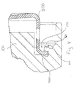
FIG. 3 is a cross-sectional view of a portion of a turbocharger of an exemplary embodiment of the present invention; and -
FIG. 4 is an enlarged cross-sectional view of portion B of the turbocharger ofFIG. 3 . - Referring to
FIGS. 3 and4 , a portion of a turbocharger is shown with a bearinghousing 100. The bearinghousing 100 defines a circumferential channel orpocket 150 at one end in proximity to the outer periphery of the bearing housing. As will be explained in more detail later, thechannel 150 is used for positioning and connecting of aheat shield 200 to the bearinghousing 100. - The
channel 150 is preferably concentrically aligned with a turbine wheel orrotor 250. Theheat shield 200 has acenter hole 210 therethrough. Thecenter hole 210 is preferably concentrically aligned with theturbine wheel 250 and allows for passage of ashaft 220 therethrough. Theshaft 220 is connected at an opposite end to a compressor wheel (not shown). - The
heat shield 200 provides thermal protection for components of the turbocharger including thelubrication system 230. Various other components are usable with the turbocharger of this exemplary embodiment, but which have not been described. Such other components, include, but are not limited to, a turbine housing, an outer guiding grid of guide vanes, a support ring, an actuation device, and a control housing. - In order to maintain the
heat shield 200 securely in position with respect to the bearinghousing 100, one or more portions of the bearing housing are deformed and pressed against the heat shield. The particular tool used for the deformation process can be chosen to facilitate manufacture, while providing sufficient strength for the connection between the bearinghousing 100 and theheat shield 200, which will be subjected to the harsh environment of the turbocharger. - In the exemplary embodiment of
FIGS. 3 and4 , astaking tool 300 is used for deforming the bearinghousing 100 and creating one or more connectingprojections 400. The size, shape and number of the connectingprojections 400 can be chosen to facilitate the process, provide sufficient strength to the connection between theheat shield 200 and the bearinghousing 100, and based on other factors including time and cost of manufacture. The present disclosure contemplates the use of a plurality of connectingprojections 400 that are equally spaced apart along the circumference of theheat shield 200 so that the loads are equally or substantially equally distributed amongst the projections. However, other configurations of connectingprojections 400 are also contemplated by the present disclosure, including a single connectingprojection 400 that is a flange circumscribing theentire heat shield 200 and pressed against the heat shield. The number, shape, size, spacing and/or configuration of the connectingprojections 400 can be controlled by theparticular staking tool 300 that is utilized to form the projections. - As shown in the enlarged view of
FIG. 4 , the one or more connectingprojections 400 are preferably formed along theouter edge 160 of thechannel 150. By deforming the bearinghousing 100 along thisedge 160, the deformation process is facilitated. Preferably, the size and shape of thechannel 150 is within a tight tolerance of the size and shape of the outer periphery of theheat shield 200. More preferably, theheat shield 200 has aflange 260 with a size and shape that is similar to the size and shape of thechannel 150 so that the heat shield can be inserted into the channel and temporarily held there during the staking process. However, other shapes and sizes of the outer periphery of theheat shield 200 are contemplated by the present disclosure, with or without aflange 260. Additionally, the exemplary embodiment has aheat shield 200 with aninner wall 205 that tapers towards thecenter hole 210 to provide a concave surface of the heat shield. However, the present disclosure contemplates other shapes of theheat shield 200 including cylindrical. - The
channel 150 is preferably an annular channel having a uniform depth and width that corresponds substantially to theflange 260 of theheat shield 200. By providing such auniform channel 150, the orientation of theheat shield 200 with respect to thechannel 150 does not matter during the staking process as described below. However, the present disclosure also contemplates other shapes for thechannel 150, which would correspond to the shape of theheat shield 200, including keys or the like in the channel that could orient the heat shield in a desired orientation. - In an exemplary embodiment, the deformation process begins with insertion of the
flange 160 of theheat shield 200 into thechannel 150. Due to the tight tolerances, theheat shield 200 can be press-fit therein while thestaking tool 300 is being positioned. Thestaking tool 300 is positioned against theedge 160 and a compressive force is applied to the tool resulting in formation of the connectingprojections 400 via the compression stakes 325. In a preferred embodiment, thestaking tool 300 needs only to move in a direction towards the bearinghousing 100 to form the connectingprojections 400. However, the present disclosure contemplates other techniques and types of staking tools, such as, for example, a staking tool that compresses and rotates. - Typically, the bearing
housing 200 is made from cast iron and more typically grey cast iron, which can be readily deformed by thestaking tool 300. Other techniques can be used in combination with the process described above, including the addition of heat to facilitate the process. - While the present disclosure has been described with respect to a turbocharger having variable geometry guide vanes, it should be understood that the exemplary embodiment of the heat shield assembly and the process of assembly can be used with other types of turbochargers.
- While the invention has been described by reference to a specific embodiment chosen for purposes of illustration, it should be apparent that numerous modifications could be made thereto by those skilled in the art without departing from the scope of the invention, as defined in the claims.
Claims (8)
- A turbocharger comprising:a bearing housing (100);a shaft (220) mounted for rotation in said bearing housing (100);with a lubrication system (230) for directing flow of lubricant to said shaft in said bearing housing;a turbine wheel (250) attached to one end of said shaft and adapted to be driven by exhaust gas flow;a heat shield (200) isolating the lubrication system (230) from the turbine wheel (250) and being positioned between the bearing housing (100) and the turbine wheel (250); and characterized byat least one connecting projection (400) that presses against the heat shield (200),whereinthe heat shield (200) is connected to the bearing housing (100) using the at least one connecting projection (400), and wherein the at least one connecting projection (400) is a projecting portion of the bearing housing (100).
- The turbocharger of claim 1, wherein the bearing housing (100) has a recess (150) dimensioned for receiving said heat shield (200), and wherein at least a portion of the heat shield (200) is positioned in the recess (150).
- The turbocharger of claim 2, wherein the recess (150) and the heat shield (200) are dimensioned such that the heat shield (200) is pressed fit into said recess (150).
- The turbocharger of claim 2, wherein the recess is bordered by a lip, and wherein the at least one connecting projection (400) is formed from a deformation at the lip (160) of the recess (150).
- A method of assembling a turbocharger comprising:positioning a heat shield (200) against a bearing housing (100) such that following final assembly said heat shield will be positioned between the bearing housing and a turbine wheel (250); and characterized bydeforming at least one portion of the bearing housing (100) thereby forming at least one connecting projection (400) pressing against the heat shield (200), the at least one connecting projection (400) pressing against the heat shield (200) whereby the heat shield (200) is connected to the bearing housing.
- The method of claim 5, wherein the deforming is by compression staking, and wherein said compression staking is performed by a staking tool (300) having a plurality of compression stakes (325) to form the at least one connecting projection (400).
- The method of claim 6, further comprising press-fitting the heat shield (200) into an annular recess (150) of the bearing housing (100) prior to the compression staking of the bearing housing (100).
- The method of claim 7, wherein the at least one connecting projection (400) is a plurality of connecting projections (400).
Applications Claiming Priority (2)
| Application Number | Priority Date | Filing Date | Title |
|---|---|---|---|
| US86386506P | 2006-11-01 | 2006-11-01 | |
| PCT/US2007/082984 WO2008057846A1 (en) | 2006-11-01 | 2007-10-30 | Turbine heat shield assembly |
Publications (3)
| Publication Number | Publication Date |
|---|---|
| EP2094957A1 EP2094957A1 (en) | 2009-09-02 |
| EP2094957A4 EP2094957A4 (en) | 2013-04-24 |
| EP2094957B1 true EP2094957B1 (en) | 2016-06-29 |
Family
ID=39364843
Family Applications (1)
| Application Number | Title | Priority Date | Filing Date |
|---|---|---|---|
| EP07854510.0A Active EP2094957B1 (en) | 2006-11-01 | 2007-10-30 | Turbine heat shield assembly |
Country Status (6)
| Country | Link |
|---|---|
| US (1) | US8376721B2 (en) |
| EP (1) | EP2094957B1 (en) |
| JP (1) | JP5238711B2 (en) |
| KR (1) | KR101304390B1 (en) |
| CN (1) | CN101529063B (en) |
| WO (1) | WO2008057846A1 (en) |
Families Citing this family (30)
| Publication number | Priority date | Publication date | Assignee | Title |
|---|---|---|---|---|
| US7559199B2 (en) * | 2006-09-22 | 2009-07-14 | Honeywell International Inc. | Variable-nozzle cartridge for a turbocharger |
| EP2261482B1 (en) * | 2008-04-08 | 2017-11-29 | IHI Corporation | Turbocharger |
| KR101340686B1 (en) * | 2009-04-24 | 2013-12-12 | 미츠비시 쥬고교 가부시키가이샤 | Hybrid exhaust turbine supercharger |
| GB201015679D0 (en) * | 2010-09-20 | 2010-10-27 | Cummins Ltd | Variable geometry turbine |
| DE102011114060A1 (en) * | 2011-09-22 | 2013-03-28 | Ihi Charging Systems International Gmbh | Heat shield for an exhaust gas turbocharger and arrangement of a heat shield between two housing parts of an exhaust gas turbocharger |
| US10041376B2 (en) | 2013-04-12 | 2018-08-07 | Borgwarner Inc. | Exhaust-gas turbocharger |
| US9909589B2 (en) * | 2014-01-15 | 2018-03-06 | General Electric Company | Rotary machine having a volute assembly-bearing housing joint with interlocking teeth |
| US20160363136A1 (en) * | 2014-01-31 | 2016-12-15 | Borgwarner Inc. | Method of retaining a noise attenuation device in a compressor cover |
| US20160265539A1 (en) * | 2015-03-09 | 2016-09-15 | Caterpillar Inc. | Compressor assembly having a matched shim |
| US9739238B2 (en) | 2015-03-09 | 2017-08-22 | Caterpillar Inc. | Turbocharger and method |
| US9915172B2 (en) | 2015-03-09 | 2018-03-13 | Caterpillar Inc. | Turbocharger with bearing piloted compressor wheel |
| US9683520B2 (en) | 2015-03-09 | 2017-06-20 | Caterpillar Inc. | Turbocharger and method |
| US10066639B2 (en) | 2015-03-09 | 2018-09-04 | Caterpillar Inc. | Compressor assembly having a vaneless space |
| US10006341B2 (en) | 2015-03-09 | 2018-06-26 | Caterpillar Inc. | Compressor assembly having a diffuser ring with tabs |
| US9752536B2 (en) | 2015-03-09 | 2017-09-05 | Caterpillar Inc. | Turbocharger and method |
| US9650913B2 (en) | 2015-03-09 | 2017-05-16 | Caterpillar Inc. | Turbocharger turbine containment structure |
| US9810238B2 (en) | 2015-03-09 | 2017-11-07 | Caterpillar Inc. | Turbocharger with turbine shroud |
| US9879594B2 (en) | 2015-03-09 | 2018-01-30 | Caterpillar Inc. | Turbocharger turbine nozzle and containment structure |
| US9890788B2 (en) | 2015-03-09 | 2018-02-13 | Caterpillar Inc. | Turbocharger and method |
| US9822700B2 (en) | 2015-03-09 | 2017-11-21 | Caterpillar Inc. | Turbocharger with oil containment arrangement |
| US9903225B2 (en) | 2015-03-09 | 2018-02-27 | Caterpillar Inc. | Turbocharger with low carbon steel shaft |
| US9777747B2 (en) | 2015-03-09 | 2017-10-03 | Caterpillar Inc. | Turbocharger with dual-use mounting holes |
| US9732633B2 (en) | 2015-03-09 | 2017-08-15 | Caterpillar Inc. | Turbocharger turbine assembly |
| US9638138B2 (en) | 2015-03-09 | 2017-05-02 | Caterpillar Inc. | Turbocharger and method |
| DE102015204563A1 (en) * | 2015-03-13 | 2016-09-15 | Bayerische Motoren Werke Aktiengesellschaft | turbocharger |
| US10371005B2 (en) | 2016-07-20 | 2019-08-06 | United Technologies Corporation | Multi-ply heat shield assembly with integral band clamp for a gas turbine engine |
| WO2018052025A1 (en) * | 2016-09-15 | 2018-03-22 | 株式会社Ihi | Supercharger and method for assembling supercharger |
| US10465556B2 (en) | 2017-10-17 | 2019-11-05 | Borgwarner Inc. | Turbocharger heat shield |
| EP3795799A1 (en) | 2019-09-20 | 2021-03-24 | BMTS Technology GmbH & Co. KG | Disc spring for an exhaust gas turbocharger |
| CN117916453A (en) * | 2021-07-06 | 2024-04-19 | 涡轮增压系统瑞士有限公司 | Low wear turbine housing clamp connection |
Family Cites Families (25)
| Publication number | Priority date | Publication date | Assignee | Title |
|---|---|---|---|---|
| US4705463A (en) | 1983-04-21 | 1987-11-10 | The Garrett Corporation | Compressor wheel assembly for turbochargers |
| US4907952A (en) * | 1986-12-05 | 1990-03-13 | Honda Giken Kogyo Kabushiki Kaisha | Turbocharger |
| JPS63118338U (en) * | 1987-01-23 | 1988-07-30 | ||
| JPH01134025A (en) * | 1987-11-17 | 1989-05-26 | Honda Motor Co Ltd | Housing structure for turbo-charger |
| US5403150A (en) * | 1988-04-28 | 1995-04-04 | Teledyne Industries, Inc. | Bearing insulating system for aircraft turbocharger |
| US5028208A (en) * | 1989-01-10 | 1991-07-02 | Ishikawajima-Harima Jukogyo Kabushiki Kaisha | Nozzle blade angle adjustment device for variable geometry turbocharger |
| US4969805A (en) * | 1989-05-02 | 1990-11-13 | Allied-Signal Inc. | Unidirectional turbocharger assembly |
| US5210945A (en) * | 1991-05-22 | 1993-05-18 | Ngk Spark Plug Co., Ltd. | Method of assembly of a rotary shaft in a ball-bearing type turbocharger |
| US5161960A (en) * | 1991-11-12 | 1992-11-10 | Allied-Signal Inc. | Turbocharger with liquid cooled housing |
| US5441383A (en) * | 1992-05-21 | 1995-08-15 | Alliedsignal Inc. | Variable exhaust driven turbochargers |
| US5295785A (en) | 1992-12-23 | 1994-03-22 | Caterpillar Inc. | Turbocharger having reduced noise emissions |
| JP3351078B2 (en) | 1993-12-27 | 2002-11-25 | 石川島播磨重工業株式会社 | Turbocharger |
| DE19540060A1 (en) * | 1995-10-27 | 1997-04-30 | Daimler Benz Ag | Engine brake device |
| US5890881A (en) * | 1996-11-27 | 1999-04-06 | Alliedsignal Inc. | Pressure balanced turbocharger rotating seal |
| US6145313A (en) * | 1997-03-03 | 2000-11-14 | Allied Signal Inc. | Turbocharger incorporating an integral pump for exhaust gas recirculation |
| US6464034B1 (en) * | 1999-02-04 | 2002-10-15 | Ntn Corporation | Electrically powered steering device |
| US6164931A (en) | 1999-12-15 | 2000-12-26 | Caterpillar Inc. | Compressor wheel assembly for turbochargers |
| CN1289791C (en) * | 2000-07-19 | 2006-12-13 | 霍尼韦尔加勒特股份有限公司 | Sliding vane turbocharger with graduated vanes |
| JP2003227344A (en) * | 2001-11-28 | 2003-08-15 | Hitachi Ltd | Turbocharger |
| DE10209484B4 (en) * | 2002-03-05 | 2004-06-24 | Borgwarner Turbo Systems Gmbh | Turbocharger for vehicles with improved suspension for the actuation mechanism of the variable nozzles |
| DE10262006B4 (en) * | 2002-03-05 | 2005-09-22 | Borgwarner Turbo Systems Gmbh | Turbocharger for vehicles with improved suspension for the actuating mechanism of the variable nozzles |
| JP2003307105A (en) | 2002-04-12 | 2003-10-31 | Fuji Oozx Inc | Engine valve |
| GB0227473D0 (en) * | 2002-11-25 | 2002-12-31 | Leavesley Malcolm G | Variable turbocharger apparatus with bypass apertures |
| DE10256418A1 (en) * | 2002-12-02 | 2004-06-09 | Abb Turbo Systems Ag | Exhaust turbine housing |
| US7360361B2 (en) * | 2005-04-09 | 2008-04-22 | Advanced Propulsion Technologies, Inc. | Turbocharger |
-
2007
- 2007-10-30 US US12/444,742 patent/US8376721B2/en active Active
- 2007-10-30 EP EP07854510.0A patent/EP2094957B1/en active Active
- 2007-10-30 KR KR1020097008723A patent/KR101304390B1/en active IP Right Grant
- 2007-10-30 WO PCT/US2007/082984 patent/WO2008057846A1/en active Application Filing
- 2007-10-30 CN CN2007800388000A patent/CN101529063B/en active Active
- 2007-10-30 JP JP2009534938A patent/JP5238711B2/en active Active
Also Published As
| Publication number | Publication date |
|---|---|
| WO2008057846A1 (en) | 2008-05-15 |
| EP2094957A4 (en) | 2013-04-24 |
| EP2094957A1 (en) | 2009-09-02 |
| US20100043431A1 (en) | 2010-02-25 |
| JP2010508465A (en) | 2010-03-18 |
| KR20090078809A (en) | 2009-07-20 |
| CN101529063A (en) | 2009-09-09 |
| KR101304390B1 (en) | 2013-09-05 |
| JP5238711B2 (en) | 2013-07-17 |
| CN101529063B (en) | 2011-11-09 |
| US8376721B2 (en) | 2013-02-19 |
Similar Documents
| Publication | Publication Date | Title |
|---|---|---|
| EP2094957B1 (en) | Turbine heat shield assembly | |
| KR100917551B1 (en) | Turbocharger with variable nozzle | |
| US9879689B2 (en) | Turbocharger rotating assembly | |
| US6168375B1 (en) | Spring-loaded vaned diffuser | |
| US6418722B1 (en) | Turbocharger bearing system | |
| US20150049967A1 (en) | Systems and methods for protecting a turbocharger aluminum bearing housing | |
| WO2013106303A1 (en) | Sealing system and turbocharger incorporating the same | |
| US20160115909A1 (en) | Turbocharger thrust bearing debris trap | |
| EP3445951B1 (en) | Turbocharger heat shield | |
| EP2176529B1 (en) | Variable geometry turbocharger with stand-off members | |
| KR20170131492A (en) | Oil deflector with oil guide | |
| EP3234310B1 (en) | A turbocharger, and a method for manufacturing a turbocharger | |
| EP3502421A1 (en) | A gas turbine engine triple bend finger seal | |
| US6338614B1 (en) | Turbocharger annular seal gland | |
| US11236667B2 (en) | Flap device for opening and closing a wastegate channel in a turbine housing of a turbocharger, turbocharger, and method for production | |
| EP4124734A1 (en) | An internal combustion engine system | |
| EP3772569B1 (en) | Actuator assembly with sealing arrangement | |
| EP4206443A1 (en) | Turbocharger flexible bearing cartridge assembly |
Legal Events
| Date | Code | Title | Description |
|---|---|---|---|
| PUAI | Public reference made under article 153(3) epc to a published international application that has entered the european phase |
Free format text: ORIGINAL CODE: 0009012 |
|
| 17P | Request for examination filed |
Effective date: 20090511 |
|
| AK | Designated contracting states |
Kind code of ref document: A1 Designated state(s): AT BE BG CH CY CZ DE DK EE ES FI FR GB GR HU IE IS IT LI LT LU LV MC MT NL PL PT RO SE SI SK TR |
|
| DAX | Request for extension of the european patent (deleted) | ||
| A4 | Supplementary search report drawn up and despatched |
Effective date: 20130325 |
|
| RIC1 | Information provided on ipc code assigned before grant |
Ipc: F02B 37/00 20060101ALI20130319BHEP Ipc: F02C 6/12 20060101ALI20130319BHEP Ipc: F02B 39/14 20060101AFI20130319BHEP Ipc: F02B 39/00 20060101ALI20130319BHEP |
|
| 17Q | First examination report despatched |
Effective date: 20131118 |
|
| GRAP | Despatch of communication of intention to grant a patent |
Free format text: ORIGINAL CODE: EPIDOSNIGR1 |
|
| INTG | Intention to grant announced |
Effective date: 20160224 |
|
| GRAS | Grant fee paid |
Free format text: ORIGINAL CODE: EPIDOSNIGR3 |
|
| GRAA | (expected) grant |
Free format text: ORIGINAL CODE: 0009210 |
|
| AK | Designated contracting states |
Kind code of ref document: B1 Designated state(s): AT BE BG CH CY CZ DE DK EE ES FI FR GB GR HU IE IS IT LI LT LU LV MC MT NL PL PT RO SE SI SK TR |
|
| REG | Reference to a national code |
Ref country code: GB Ref legal event code: FG4D |
|
| REG | Reference to a national code |
Ref country code: CH Ref legal event code: EP |
|
| REG | Reference to a national code |
Ref country code: AT Ref legal event code: REF Ref document number: 809289 Country of ref document: AT Kind code of ref document: T Effective date: 20160715 |
|
| REG | Reference to a national code |
Ref country code: IE Ref legal event code: FG4D |
|
| REG | Reference to a national code |
Ref country code: DE Ref legal event code: R096 Ref document number: 602007046838 Country of ref document: DE |
|
| REG | Reference to a national code |
Ref country code: FR Ref legal event code: PLFP Year of fee payment: 10 |
|
| REG | Reference to a national code |
Ref country code: LT Ref legal event code: MG4D |
|
| PG25 | Lapsed in a contracting state [announced via postgrant information from national office to epo] |
Ref country code: LT Free format text: LAPSE BECAUSE OF FAILURE TO SUBMIT A TRANSLATION OF THE DESCRIPTION OR TO PAY THE FEE WITHIN THE PRESCRIBED TIME-LIMIT Effective date: 20160629 Ref country code: FI Free format text: LAPSE BECAUSE OF FAILURE TO SUBMIT A TRANSLATION OF THE DESCRIPTION OR TO PAY THE FEE WITHIN THE PRESCRIBED TIME-LIMIT Effective date: 20160629 |
|
| REG | Reference to a national code |
Ref country code: NL Ref legal event code: MP Effective date: 20160629 |
|
| PG25 | Lapsed in a contracting state [announced via postgrant information from national office to epo] |
Ref country code: GR Free format text: LAPSE BECAUSE OF FAILURE TO SUBMIT A TRANSLATION OF THE DESCRIPTION OR TO PAY THE FEE WITHIN THE PRESCRIBED TIME-LIMIT Effective date: 20160930 Ref country code: SE Free format text: LAPSE BECAUSE OF FAILURE TO SUBMIT A TRANSLATION OF THE DESCRIPTION OR TO PAY THE FEE WITHIN THE PRESCRIBED TIME-LIMIT Effective date: 20160629 Ref country code: NL Free format text: LAPSE BECAUSE OF FAILURE TO SUBMIT A TRANSLATION OF THE DESCRIPTION OR TO PAY THE FEE WITHIN THE PRESCRIBED TIME-LIMIT Effective date: 20160629 Ref country code: LV Free format text: LAPSE BECAUSE OF FAILURE TO SUBMIT A TRANSLATION OF THE DESCRIPTION OR TO PAY THE FEE WITHIN THE PRESCRIBED TIME-LIMIT Effective date: 20160629 |
|
| REG | Reference to a national code |
Ref country code: AT Ref legal event code: MK05 Ref document number: 809289 Country of ref document: AT Kind code of ref document: T Effective date: 20160629 |
|
| PG25 | Lapsed in a contracting state [announced via postgrant information from national office to epo] |
Ref country code: IT Free format text: LAPSE BECAUSE OF FAILURE TO SUBMIT A TRANSLATION OF THE DESCRIPTION OR TO PAY THE FEE WITHIN THE PRESCRIBED TIME-LIMIT Effective date: 20160629 Ref country code: RO Free format text: LAPSE BECAUSE OF FAILURE TO SUBMIT A TRANSLATION OF THE DESCRIPTION OR TO PAY THE FEE WITHIN THE PRESCRIBED TIME-LIMIT Effective date: 20160629 Ref country code: IS Free format text: LAPSE BECAUSE OF FAILURE TO SUBMIT A TRANSLATION OF THE DESCRIPTION OR TO PAY THE FEE WITHIN THE PRESCRIBED TIME-LIMIT Effective date: 20161029 Ref country code: CZ Free format text: LAPSE BECAUSE OF FAILURE TO SUBMIT A TRANSLATION OF THE DESCRIPTION OR TO PAY THE FEE WITHIN THE PRESCRIBED TIME-LIMIT Effective date: 20160629 Ref country code: SK Free format text: LAPSE BECAUSE OF FAILURE TO SUBMIT A TRANSLATION OF THE DESCRIPTION OR TO PAY THE FEE WITHIN THE PRESCRIBED TIME-LIMIT Effective date: 20160629 Ref country code: EE Free format text: LAPSE BECAUSE OF FAILURE TO SUBMIT A TRANSLATION OF THE DESCRIPTION OR TO PAY THE FEE WITHIN THE PRESCRIBED TIME-LIMIT Effective date: 20160629 |
|
| PG25 | Lapsed in a contracting state [announced via postgrant information from national office to epo] |
Ref country code: BE Free format text: LAPSE BECAUSE OF NON-PAYMENT OF DUE FEES Effective date: 20160629 Ref country code: ES Free format text: LAPSE BECAUSE OF FAILURE TO SUBMIT A TRANSLATION OF THE DESCRIPTION OR TO PAY THE FEE WITHIN THE PRESCRIBED TIME-LIMIT Effective date: 20160629 Ref country code: PL Free format text: LAPSE BECAUSE OF FAILURE TO SUBMIT A TRANSLATION OF THE DESCRIPTION OR TO PAY THE FEE WITHIN THE PRESCRIBED TIME-LIMIT Effective date: 20160629 Ref country code: AT Free format text: LAPSE BECAUSE OF FAILURE TO SUBMIT A TRANSLATION OF THE DESCRIPTION OR TO PAY THE FEE WITHIN THE PRESCRIBED TIME-LIMIT Effective date: 20160629 Ref country code: PT Free format text: LAPSE BECAUSE OF FAILURE TO SUBMIT A TRANSLATION OF THE DESCRIPTION OR TO PAY THE FEE WITHIN THE PRESCRIBED TIME-LIMIT Effective date: 20161031 |
|
| REG | Reference to a national code |
Ref country code: DE Ref legal event code: R097 Ref document number: 602007046838 Country of ref document: DE |
|
| PLBE | No opposition filed within time limit |
Free format text: ORIGINAL CODE: 0009261 |
|
| STAA | Information on the status of an ep patent application or granted ep patent |
Free format text: STATUS: NO OPPOSITION FILED WITHIN TIME LIMIT |
|
| PG25 | Lapsed in a contracting state [announced via postgrant information from national office to epo] |
Ref country code: DK Free format text: LAPSE BECAUSE OF FAILURE TO SUBMIT A TRANSLATION OF THE DESCRIPTION OR TO PAY THE FEE WITHIN THE PRESCRIBED TIME-LIMIT Effective date: 20160629 |
|
| REG | Reference to a national code |
Ref country code: CH Ref legal event code: PL |
|
| 26N | No opposition filed |
Effective date: 20170330 |
|
| STAA | Information on the status of an ep patent application or granted ep patent |
Free format text: STATUS: NO OPPOSITION FILED WITHIN TIME LIMIT |
|
| REG | Reference to a national code |
Ref country code: IE Ref legal event code: MM4A |
|
| PG25 | Lapsed in a contracting state [announced via postgrant information from national office to epo] |
Ref country code: CH Free format text: LAPSE BECAUSE OF NON-PAYMENT OF DUE FEES Effective date: 20161031 Ref country code: LI Free format text: LAPSE BECAUSE OF NON-PAYMENT OF DUE FEES Effective date: 20161031 |
|
| PG25 | Lapsed in a contracting state [announced via postgrant information from national office to epo] |
Ref country code: LU Free format text: LAPSE BECAUSE OF NON-PAYMENT OF DUE FEES Effective date: 20161030 Ref country code: BG Free format text: LAPSE BECAUSE OF FAILURE TO SUBMIT A TRANSLATION OF THE DESCRIPTION OR TO PAY THE FEE WITHIN THE PRESCRIBED TIME-LIMIT Effective date: 20160929 Ref country code: SI Free format text: LAPSE BECAUSE OF FAILURE TO SUBMIT A TRANSLATION OF THE DESCRIPTION OR TO PAY THE FEE WITHIN THE PRESCRIBED TIME-LIMIT Effective date: 20160629 |
|
| REG | Reference to a national code |
Ref country code: FR Ref legal event code: PLFP Year of fee payment: 11 |
|
| PG25 | Lapsed in a contracting state [announced via postgrant information from national office to epo] |
Ref country code: IE Free format text: LAPSE BECAUSE OF NON-PAYMENT OF DUE FEES Effective date: 20161030 |
|
| PG25 | Lapsed in a contracting state [announced via postgrant information from national office to epo] |
Ref country code: CY Free format text: LAPSE BECAUSE OF FAILURE TO SUBMIT A TRANSLATION OF THE DESCRIPTION OR TO PAY THE FEE WITHIN THE PRESCRIBED TIME-LIMIT Effective date: 20160629 Ref country code: HU Free format text: LAPSE BECAUSE OF FAILURE TO SUBMIT A TRANSLATION OF THE DESCRIPTION OR TO PAY THE FEE WITHIN THE PRESCRIBED TIME-LIMIT; INVALID AB INITIO Effective date: 20071030 |
|
| PG25 | Lapsed in a contracting state [announced via postgrant information from national office to epo] |
Ref country code: MT Free format text: LAPSE BECAUSE OF NON-PAYMENT OF DUE FEES Effective date: 20161031 Ref country code: MC Free format text: LAPSE BECAUSE OF FAILURE TO SUBMIT A TRANSLATION OF THE DESCRIPTION OR TO PAY THE FEE WITHIN THE PRESCRIBED TIME-LIMIT Effective date: 20160629 Ref country code: TR Free format text: LAPSE BECAUSE OF FAILURE TO SUBMIT A TRANSLATION OF THE DESCRIPTION OR TO PAY THE FEE WITHIN THE PRESCRIBED TIME-LIMIT Effective date: 20160629 |
|
| REG | Reference to a national code |
Ref country code: FR Ref legal event code: PLFP Year of fee payment: 12 |
|
| PGFP | Annual fee paid to national office [announced via postgrant information from national office to epo] |
Ref country code: GB Payment date: 20200930 Year of fee payment: 14 Ref country code: FR Payment date: 20200923 Year of fee payment: 14 |
|
| GBPC | Gb: european patent ceased through non-payment of renewal fee |
Effective date: 20211030 |
|
| PG25 | Lapsed in a contracting state [announced via postgrant information from national office to epo] |
Ref country code: GB Free format text: LAPSE BECAUSE OF NON-PAYMENT OF DUE FEES Effective date: 20211030 |
|
| PG25 | Lapsed in a contracting state [announced via postgrant information from national office to epo] |
Ref country code: FR Free format text: LAPSE BECAUSE OF NON-PAYMENT OF DUE FEES Effective date: 20211031 |
|
| P01 | Opt-out of the competence of the unified patent court (upc) registered |
Effective date: 20230327 |
|
| PGFP | Annual fee paid to national office [announced via postgrant information from national office to epo] |
Ref country code: DE Payment date: 20230915 Year of fee payment: 17 |