EP2094941B1 - Metallplatte für stufenzementierung einer ölquelle - Google Patents
Metallplatte für stufenzementierung einer ölquelle Download PDFInfo
- Publication number
- EP2094941B1 EP2094941B1 EP07870898.9A EP07870898A EP2094941B1 EP 2094941 B1 EP2094941 B1 EP 2094941B1 EP 07870898 A EP07870898 A EP 07870898A EP 2094941 B1 EP2094941 B1 EP 2094941B1
- Authority
- EP
- European Patent Office
- Prior art keywords
- casing
- plate
- inner casing
- steel plate
- outer casing
- Prior art date
- Legal status (The legal status is an assumption and is not a legal conclusion. Google has not performed a legal analysis and makes no representation as to the accuracy of the status listed.)
- Not-in-force
Links
- 239000003129 oil well Substances 0.000 title claims description 4
- 229910052751 metal Inorganic materials 0.000 title description 3
- 239000002184 metal Substances 0.000 title description 3
- 239000004568 cement Substances 0.000 claims description 50
- 239000002002 slurry Substances 0.000 claims description 27
- 238000000034 method Methods 0.000 claims description 17
- 238000005553 drilling Methods 0.000 claims description 16
- 239000012530 fluid Substances 0.000 claims description 16
- 229910000831 Steel Inorganic materials 0.000 claims description 14
- 239000010959 steel Substances 0.000 claims description 14
- 239000008187 granular material Substances 0.000 claims description 7
- 238000005086 pumping Methods 0.000 claims description 6
- 230000008878 coupling Effects 0.000 claims description 4
- 238000010168 coupling process Methods 0.000 claims description 4
- 238000005859 coupling reaction Methods 0.000 claims description 4
- 238000004519 manufacturing process Methods 0.000 claims description 2
- 238000000151 deposition Methods 0.000 claims 1
- 230000015572 biosynthetic process Effects 0.000 description 3
- 239000000463 material Substances 0.000 description 3
- 125000006850 spacer group Chemical group 0.000 description 3
- VTYYLEPIZMXCLO-UHFFFAOYSA-L Calcium carbonate Chemical compound [Ca+2].[O-]C([O-])=O VTYYLEPIZMXCLO-UHFFFAOYSA-L 0.000 description 2
- XLYOFNOQVPJJNP-UHFFFAOYSA-N water Substances O XLYOFNOQVPJJNP-UHFFFAOYSA-N 0.000 description 2
- 230000004888 barrier function Effects 0.000 description 1
- 230000000903 blocking effect Effects 0.000 description 1
- 229910001385 heavy metal Inorganic materials 0.000 description 1
- 230000006872 improvement Effects 0.000 description 1
- 238000009434 installation Methods 0.000 description 1
- 238000012986 modification Methods 0.000 description 1
- 230000004048 modification Effects 0.000 description 1
- 230000008569 process Effects 0.000 description 1
- 230000002250 progressing effect Effects 0.000 description 1
- 239000011435 rock Substances 0.000 description 1
- 239000004576 sand Substances 0.000 description 1
- 239000002689 soil Substances 0.000 description 1
- 238000012144 step-by-step procedure Methods 0.000 description 1
Images


Classifications
-
- E—FIXED CONSTRUCTIONS
- E21—EARTH OR ROCK DRILLING; MINING
- E21B—EARTH OR ROCK DRILLING; OBTAINING OIL, GAS, WATER, SOLUBLE OR MELTABLE MATERIALS OR A SLURRY OF MINERALS FROM WELLS
- E21B33/00—Sealing or packing boreholes or wells
- E21B33/10—Sealing or packing boreholes or wells in the borehole
- E21B33/13—Methods or devices for cementing, for plugging holes, crevices or the like
- E21B33/14—Methods or devices for cementing, for plugging holes, crevices or the like for cementing casings into boreholes
- E21B33/146—Stage cementing, i.e. discharging cement from casing at different levels
-
- E—FIXED CONSTRUCTIONS
- E21—EARTH OR ROCK DRILLING; MINING
- E21B—EARTH OR ROCK DRILLING; OBTAINING OIL, GAS, WATER, SOLUBLE OR MELTABLE MATERIALS OR A SLURRY OF MINERALS FROM WELLS
- E21B33/00—Sealing or packing boreholes or wells
- E21B33/10—Sealing or packing boreholes or wells in the borehole
- E21B33/13—Methods or devices for cementing, for plugging holes, crevices or the like
- E21B33/136—Baskets, e.g. of umbrella type
Definitions
- the invention relates to the step in the completion of oil wells in which the annular space between an outer casing and a smaller diameter inner casing that extends from the earth's surface is filled with cement.
- the outer casing may extend to a depth of 1,000 feet/330m, or more, and is required to provide a barrier for the drilling operation and protect and stabilize the inner casing at the upper layer of the earth's surface where the subsurface is unconsolidated material.
- the inner casing alone is lowered to the final drilling depth, which may be 4,000 feet/1300m, or more.
- the inner casing is stabilized and rigidly secured in place by cementing the annular space between the two casings. Such a method is shown in US 6622798 .
- a stage-cementing tool is to enable the operator to fill the annulus between the inner and outer surface casing strings with cement slurry when there is a loss circulation zone below the bottom of the outer casing.
- a lost circulation zone is one in which a cement slurry, drilling mud or other fluids cannot be contained in the well bore and are dissipated and lost in the surrounding formation. This is an undesirable condition and must be rectified.
- One conventional stage-cementing tool consists of an inflatable packer element and a diverting tool (DV tool) above the packer.
- the tool is connected to the inner casing and run in the well to a depth of 50 to 100 ft above the bottom of the outer casing.
- a heavy metal object referred to in the art as a "metal bomb" is dropped in the casing.
- the bomb falls freely in the drilling fluid in the casing and seats in the stage-cementing tool.
- Hydraulic pressure is applied from the surface to shift a sleeve and open a port in the stage cementing tool.
- Drilling fluid is pumped into the port to inflate the packer of the stage tool and form a seal with the outer casing. Higher pressure is then applied to open ports in the diverting tool above the packer.
- a known volume of cement slurry is pumped down the inner casing.
- a closing plug is dropped into the casing and drilling fluid is pumped to displace the plug and cement. The cement enters the casing annulus through the open ports in the DV tool above the packer.
- the closing plug When the closing plug reaches the stage tool it shifts a sleeve to close the ports in the DV tool. At this time, the casing annulus is full of cement from the stage tool to the surface.
- the inflated packer forms a seal with the outer casing to prevent the cement slurry from falling into the lost circulation zone below the packer.
- Cement baskets are sometimes used instead of stage-cementing tools to place cement in the casing annulus.
- Cement baskets cannot hold a large load of cement and, therefore, they are normally run to shallow depths of about 300 to 400 feet from the surface.
- Cement baskets do not form a seal with the outer casing and cement slurry can pass through the arms of the basket. For this reason the cementing job is performed by pumping cement slurry into the annulus in three to four stages to fill the annulus to the surface. After each stage the cement is allowed to harden for 3 to 4 hours before pumping the next stage. This procedure consumes excessive amount of rig time and is therefore costly.
- Another object of the invention is to provide a stage-cement tool that can be installed relatively quickly and that is sufficiently robust to support a column of cement slurry that is 1000 feet, or more, in height.
- a donut-shaped, or annular, steel plate of substantial thickness having an outer diameter that is less than the inner diameter of the outer casing is positioned on a section of the inner casing and lowered into the outer casing as part of the string.
- This device will be referred to as the stage-cementing metal plate.
- the casing and plate are lowered to within a predetermined distance, e.g., 50 feet from the down-hole end of the outer casing.
- the annular space is filled with drilling fluid and the region below the end of the outer casing is referred to as a "lost circulation zone". It is therefore necessary for a space to be provided between the outer rim of the plate and the inner wall of the outer casing in order to allow the fluid a passageway to escape as the plate is lowered through the fluid.
- Typical casing diameters are as follows: outer casing 18-5/8 inches and inner casing 13-3/8 inches, thereby defining an annular space of about 2-1/8 inches.
- the plate of the invention is circular in shape with a concentric hole for mounting on the inner casing.
- the plate is placed on the coupling of the inner casing string. Stop collars are placed on the inner casing above the plate to prevent vertical movement.
- the plate is preferably about 2.5 inches/6.25 cm thick and has an outside diameter slightly smaller than the inside diameter of the outer casing to allow fluids or cement slurry to pass between the outer rim of the plate and the outer casing.
- the plate is run on the inner casing to the desired depth above the end of the outer casing string.
- a known volume of cement slurry spacer is pumped from the surface into the annulus between the two casing strings to displace the fluids in the annulus to the lost circulation zone.
- a layer of gravel is poured into the annular space and forms a bridge to substantially fill the gap between the edge of the plate and the wall of the outer casing; simultaneously, well cement is poured into the annulus and is prevented from flowing below the annular plate by the layer of gravel.
- the entire annular space from the plate to the surface is filled with the cement slurry and allowed to harden.
- the plate remains in place supporting the column of hardened cement, which may be 3,000 feet/ 990 m in depth. The final stage of the installation and cementing is described in detail below.
- FIG. 1 there is shown the load-bearing annular steel plate used in the method of the invention in oil well cementing operation in lieu of a stage cementing tool or cement basket to retain cement slurry between two concentric casing strings above a lost circulation zone.
- the plate 10 is circular in shape with a central circular opening 14 having an inside diameter that is slightly greater than the outside diameter of the inner casing and an outside diameter equal to the drift diameter of the outer casing.
- the plate is preferably about 2.5 inches/6.25 cm thick and capable of supporting the weight of a cement column of up to 4000 ft/1300 m.
- the plate is provided with a raised shoulder 16 surrounding the central opening 14.
- the plate 10 is placed on the inner casing 20 and installed above the casing coupling 28.
- Three stop collars 30 are installed on top of the plate 10 to prevent vertical movement and contact the upper surface of shoulder 16.
- Other means for securing the plate 10 against vertical movement can be employed.
- the inner casing 20 with the plate 10 securely mounted is lowered to a position so that the plate is about 50 ft/16m above the bottom of the outer casing.
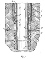
- the lower end of inner casing 20 is securely positioned in the lower borehole 21 by cement 23, which terminates below the lost circulation zone 60.
- the lower end of outer casing 40 is positioned in the upper borehole 41, and the annular space 46 between the casings 20 and 40 shown in the illustration partially filled with drilling fluid 42 that is being dissipated into the lost circulation zone 60.
- a known volume of cement slurry is pumped into the annulus 46 between the inner and outer casings at about 5 to 6 barrels per minute to form a spacer 48 and to displace the drilling fluid in the annulus above the plate 10 into the lost circulation zone below the plate.
- the pumping of cement slurry is continued until the granular material 50 reaches the plate 10 and forms a bridge or seal between the plate and the outer casing 40 blocking the flow of cement slurry around the plate as shown in FIG. 5 .
- the stage cementing plate of the present invention has a simple design with no moving parts which makes it more reliable than the conventional stage-cementing tools of the prior art.
- This apparatus and its method of use meet all of the objectives identified above and constitutes a significant improvement over the devices and methods of the prior art.
Landscapes
- Life Sciences & Earth Sciences (AREA)
- Engineering & Computer Science (AREA)
- Geology (AREA)
- Mining & Mineral Resources (AREA)
- Physics & Mathematics (AREA)
- Environmental & Geological Engineering (AREA)
- Fluid Mechanics (AREA)
- General Life Sciences & Earth Sciences (AREA)
- Geochemistry & Mineralogy (AREA)
- Consolidation Of Soil By Introduction Of Solidifying Substances Into Soil (AREA)
- Earth Drilling (AREA)
- Piles And Underground Anchors (AREA)
Claims (14)
- Verfahren für die Komplettierung eines Fluidförderbohrlochs, das sich von der Erdoberfläche erstreckt, wobei das Bohrloch ein äußeres Futterrohr mit einem unteren Endabschnitt, der unter der Oberfläche endet, und ein inneres Futterrohr aufweist, das sich von der Oberfläche zu einer Position unter dem Endabschnitt des äußeren Futterrohrs erstreckt, um dadurch einen ringförmigen Raum (46) zu definieren, wobei die Komplettierung das Füllen des ringförmigen Raums (46) vom Endabschnitt des äußeren Futterrohrs bis zur Erdoberfläche aufweist, gekennzeichnet durch die folgenden Schritte:a. Bereitstellen einer lasttragenden ringförmigen Stahlplatte (10) mit einer mittigen Öffnung zur Aufnahme eines Abschnitts des inneren Futterrohrs (20) und mit einem äußeren Durchmesser, der geringer als der innere Durchmesser des äußeren Futterrohrs (40) ist,b. Stützen der Platte (10) auf einem Abschnitt des inneren Futterrohrs (20),c. Absenken der Platte und des inneren Futterrohrs (20) zu einer Position innerhalb des unteren Endabschnitts des äußeren Futterrohrs (40),d. Platzieren eines vorbestimmten Kiesvolumens auf die obere Fläche der Stahlplatte (10), um dadurch den offenen Raum zwischen dem Rand der Platte und den benachbarten Futterrohrwänden im Wesentlichen abzudichten, unde. Gießen eines Zementschlamms in den ringförmigen Raum (46) über der Platte (10) und bis zu der Oberfläche.
- Verfahren nach Anspruch 1, gekennzeichnet durch Platzieren eines vorbestimmten Zementschlammvolumens in den Ringspalt, um vor der Platzierung des Kieses etwaige Fluide zu der Lost-Circulation-Zone zu verdrängen.
- Verfahren nach Anspruch 1, gekennzeichnet durch Befestigen mindestens eines Anschlagbunds an dem inneren Futterrohr (20), um dadurch zu verhindern, dass sich die Stahlplatte (10) bezüglich des inneren Futterrohrs (20) bewegt.
- Verfahren nach Anspruch 1, gekennzeichnet durch Positionieren der Stahlplatte ungefähr sechzig Fuß/19 m über dem Ende des äußeren Futterrohrs (40).
- Verfahren nach Anspruch 1, gekennzeichnet durch Pumpen eines Zementschlamms in den ringförmigen Raum (46) zwischen dem Futterrohr vor dem Ablegen des Kieses auf der Stahlplatte (10), um dadurch etwaiges Bohrfluid, das sich über der Platte (10) befindet, zu verdrängen.
- Verfahren nach Anspruch 1, dadurch gekennzeichnet, dass das Granulatmaterial mit Zementschlamm in den ringförmigen Raum (46) eingeführt wird.
- Verfahren nach Anspruch 1, dadurch gekennzeichnet, dass die Platte (10) an einer inneren Futterrohrkopplung gestützt wird.
- Apparat zum Einsatz bei der Stufenzementierung eines Ölbohrlochs im Bereich einer Lost-Circulation-Zone, die in der Nähe eines ringförmigen Raums liegt, der durch das untere Ende eines ein inneres Futterrohr umgebendes äußeren Futterrohrs (40) definiert ist, gekennzeichnet durch eine lasttragende ringförmige Stahlplatte (10), die unbeweglich auf einem Abschnitt des inneren Futterrohrs bezüglich der Längsachse des inneren Futterrohrs (20) positioniert ist, wobei der äußere Durchmesser der Platte (10) geringer als der innere Durchmesser des äußeren Futterrohrs (40) ist.
- Apparat nach Anspruch 8, dadurch gekennzeichnet, dass die durch die mittlere Öffnung definierte innere Fläche der Stahlplatte in eng anliegender Beziehung zu der äußeren Fläche des inneren Futterrohrs (20) steht.
- Apparat nach Anspruch 8, dadurch gekennzeichnet, dass die Dicke der Stahlplatte (10) zwei bis drei Zoll/5,1 mm bis 7,6 mm beträgt.
- Apparat nach Anspruch 8, dadurch gekennzeichnet, dass der äußere Durchmesser der ringförmigen Stahlplatte (10) ausreichend kleiner als der innere Durchmesser des äußeren Futterrohrs (40) ist, damit die Platte unbehindert durch das äußere Futterrohr (40) hinuntergehen kann.
- Apparat nach Anspruch 8, dadurch gekennzeichnet, dass die Stahlplatte durch mindestens einen am inneren Futterrohr angebrachten Anschlagbund (30) an Ort und Stelle am inneren Futterrohr (20) befestigt ist.
- Apparat nach Anspruch 8, gekennzeichnet durch eine am inneren Futterrohr (20) unter der Stahlplatte (10) montierte Kopplung, die die Platte stützt.
- Apparat nach Anspruch 8, gekennzeichnet durch mindestens einen am Futterrohr über der Stahlplatte (10) befestigten Anschlagbund (30), um eine Bewegung der Platte (10) bezüglich der Längsachse des Futterrohrs zu verhindern.
Applications Claiming Priority (2)
| Application Number | Priority Date | Filing Date | Title |
|---|---|---|---|
| US87306006P | 2006-12-05 | 2006-12-05 | |
| PCT/US2007/024106 WO2008069914A2 (en) | 2006-12-05 | 2007-11-15 | Oil well stage-cementing metal plate |
Publications (3)
| Publication Number | Publication Date |
|---|---|
| EP2094941A2 EP2094941A2 (de) | 2009-09-02 |
| EP2094941A4 EP2094941A4 (de) | 2014-09-17 |
| EP2094941B1 true EP2094941B1 (de) | 2015-10-28 |
Family
ID=39492793
Family Applications (1)
| Application Number | Title | Priority Date | Filing Date |
|---|---|---|---|
| EP07870898.9A Not-in-force EP2094941B1 (de) | 2006-12-05 | 2007-11-15 | Metallplatte für stufenzementierung einer ölquelle |
Country Status (4)
| Country | Link |
|---|---|
| US (1) | US8342243B2 (de) |
| EP (1) | EP2094941B1 (de) |
| CN (1) | CN101646838B (de) |
| WO (1) | WO2008069914A2 (de) |
Families Citing this family (7)
| Publication number | Priority date | Publication date | Assignee | Title |
|---|---|---|---|---|
| US9038720B2 (en) * | 2006-12-05 | 2015-05-26 | Saudi Arabian Oil Company | Apparatus for stage-cementing an oil well |
| CN102444111B (zh) * | 2011-10-19 | 2015-01-07 | 邓业灿 | 地下溶洞造影探测法 |
| US10364644B2 (en) | 2016-09-07 | 2019-07-30 | Saudi Arabian Oil Company | Stage cementing tool |
| US10982499B2 (en) | 2018-09-13 | 2021-04-20 | Saudi Arabian Oil Company | Casing patch for loss circulation zone |
| US11091978B2 (en) | 2019-04-22 | 2021-08-17 | Saudi Arabian Oil Company | Stage cementing an annulus of a wellbore |
| US11661816B2 (en) | 2020-05-15 | 2023-05-30 | Saudi Arabian Oil Company | Method and apparatus for cementing a casing in a wellbore |
| US11859465B2 (en) | 2021-12-08 | 2024-01-02 | Saudi Arabian Oil Company | Cement top job with non-retrievable tubing |
Family Cites Families (26)
| Publication number | Priority date | Publication date | Assignee | Title |
|---|---|---|---|---|
| US1819668A (en) * | 1929-07-13 | 1931-08-18 | Baker Oil Tools Inc | Well cementing apparatus |
| US1980985A (en) * | 1930-01-10 | 1934-11-20 | Deming Robert | Well pump |
| US3131767A (en) * | 1962-04-24 | 1964-05-05 | Forrest E Chancellor | Stage collar |
| US3313352A (en) * | 1964-04-06 | 1967-04-11 | Jr James D Tennison | Well casing protective skirt |
| US3666009A (en) * | 1970-01-23 | 1972-05-30 | Gulf Oil Corp | Method and apparatus for shutting in offshore wells |
| US3918523A (en) | 1974-07-11 | 1975-11-11 | Ivan L Stuber | Method and means for implanting casing |
| US3948322A (en) | 1975-04-23 | 1976-04-06 | Halliburton Company | Multiple stage cementing tool with inflation packer and methods of use |
| US4421165A (en) | 1980-07-15 | 1983-12-20 | Halliburton Company | Multiple stage cementer and casing inflation packer |
| US4474241A (en) * | 1983-02-14 | 1984-10-02 | Halliburton Company | Differential fill valve assembly |
| US4491178A (en) * | 1983-08-11 | 1985-01-01 | Gearhart Industries, Inc. | Through tubing bridge plug |
| US4678031A (en) | 1986-01-27 | 1987-07-07 | Blandford David M | Rotatable reciprocating collar for borehole casing |
| US5024273A (en) | 1989-09-29 | 1991-06-18 | Davis-Lynch, Inc. | Cementing apparatus and method |
| US4949788A (en) * | 1989-11-08 | 1990-08-21 | Halliburton Company | Well completions using casing valves |
| US5109925A (en) | 1991-01-17 | 1992-05-05 | Halliburton Company | Multiple stage inflation packer with secondary opening rupture disc |
| US5191932A (en) * | 1991-07-09 | 1993-03-09 | Douglas Seefried | Oilfield cementing tool and method |
| CN2228973Y (zh) * | 1995-05-27 | 1996-06-12 | 吐哈石油勘探开发会战指挥部钻井工艺研究所 | 井口密封式内管注水泥工具 |
| US5732775A (en) | 1996-08-20 | 1998-03-31 | Bestline Liner Systems, Inc. | Multiple casing segment cementing system |
| MY130896A (en) * | 2001-06-05 | 2007-07-31 | Shell Int Research | In-situ casting of well equipment |
| US6578638B2 (en) | 2001-08-27 | 2003-06-17 | Weatherford/Lamb, Inc. | Drillable inflatable packer & methods of use |
| US6715545B2 (en) * | 2002-03-27 | 2004-04-06 | Halliburton Energy Services, Inc. | Transition member for maintaining for fluid slurry velocity therethrough and method for use of same |
| US6761218B2 (en) * | 2002-04-01 | 2004-07-13 | Halliburton Energy Services, Inc. | Methods and apparatus for improving performance of gravel packing systems |
| US6622798B1 (en) * | 2002-05-08 | 2003-09-23 | Halliburton Energy Services, Inc. | Method and apparatus for maintaining a fluid column in a wellbore annulus |
| CN1508380A (zh) * | 2002-12-18 | 2004-06-30 | 杜晓瑞 | 超短曲率水平井钻井和完井的方法及其装置 |
| US20050087342A1 (en) * | 2003-10-22 | 2005-04-28 | Christensen Byron D. | Method and apparatus for cementing pipe in oil and gas wells |
| US7063164B2 (en) * | 2004-04-01 | 2006-06-20 | Schlumberger Technology Corporation | System and method to seal by bringing the wall of a wellbore into sealing contact with a tubing |
| US7290611B2 (en) * | 2004-07-22 | 2007-11-06 | Halliburton Energy Services, Inc. | Methods and systems for cementing wells that lack surface casing |
-
2007
- 2007-11-15 WO PCT/US2007/024106 patent/WO2008069914A2/en not_active Ceased
- 2007-11-15 US US12/448,544 patent/US8342243B2/en not_active Expired - Fee Related
- 2007-11-15 CN CN200780050961.1A patent/CN101646838B/zh not_active Expired - Fee Related
- 2007-11-15 EP EP07870898.9A patent/EP2094941B1/de not_active Not-in-force
Also Published As
| Publication number | Publication date |
|---|---|
| WO2008069914A3 (en) | 2008-08-07 |
| EP2094941A4 (de) | 2014-09-17 |
| US20100084135A1 (en) | 2010-04-08 |
| CN101646838A (zh) | 2010-02-10 |
| US8342243B2 (en) | 2013-01-01 |
| EP2094941A2 (de) | 2009-09-02 |
| CN101646838B (zh) | 2014-08-27 |
| WO2008069914A2 (en) | 2008-06-12 |
Similar Documents
| Publication | Publication Date | Title |
|---|---|---|
| US8267173B2 (en) | Open hole completion apparatus and method for use of same | |
| US6634430B2 (en) | Method for installation of evacuated tubular conduits | |
| EP2094941B1 (de) | Metallplatte für stufenzementierung einer ölquelle | |
| CA2637082C (en) | Reverse-circulation cementing of surface casing | |
| US8186457B2 (en) | Offshore casing drilling method | |
| US10041328B2 (en) | Method for using managed pressure drilling with epoxy resin | |
| GB2434606A (en) | Method of drilling and completing multiple wellbores from within a single wellhead | |
| CN114364861A (zh) | 球座释放设备 | |
| US20180274321A1 (en) | System and method for offline suspension or cementing of tubulars | |
| US9038720B2 (en) | Apparatus for stage-cementing an oil well | |
| CN115387793A (zh) | 一种煤矿区大直径透巷孔终孔固井方法 | |
| US5474127A (en) | Annular safety system for oil well | |
| RU2167273C1 (ru) | Способ установки хвостовика обсадной колонны в скважине | |
| AU2004265583B2 (en) | Continuous monobore liquid lining system | |
| CA2884170C (en) | Valve, system and method for completion, stimulation and subsequent re-stimulation of wells for hydrocarbon production | |
| US20100051287A1 (en) | Depressurization system of annuli between casings in producing wells | |
| US9062529B2 (en) | Gravel pack assembly and method of use | |
| US20060037752A1 (en) | Rat hole bypass for gravel packing assembly | |
| RU2474668C1 (ru) | Способ строительства скважины | |
| CN119021630A (zh) | 一种用于油井的回接固井装置及回接固井方法 |
Legal Events
| Date | Code | Title | Description |
|---|---|---|---|
| PUAI | Public reference made under article 153(3) epc to a published international application that has entered the european phase |
Free format text: ORIGINAL CODE: 0009012 |
|
| 17P | Request for examination filed |
Effective date: 20090703 |
|
| AK | Designated contracting states |
Kind code of ref document: A2 Designated state(s): AT BE BG CH CY CZ DE DK EE ES FI FR GB GR HU IE IS IT LI LT LU LV MC MT NL PL PT RO SE SI SK TR |
|
| RIC1 | Information provided on ipc code assigned before grant |
Ipc: E21B 33/00 20060101AFI20091104BHEP |
|
| RIN1 | Information on inventor provided before grant (corrected) |
Inventor name: ESMAIL, OMAR JUBRAN |
|
| DAX | Request for extension of the european patent (deleted) | ||
| A4 | Supplementary search report drawn up and despatched |
Effective date: 20140820 |
|
| RIC1 | Information provided on ipc code assigned before grant |
Ipc: E21B 33/00 20060101AFI20140813BHEP Ipc: E21B 33/129 20060101ALI20140813BHEP Ipc: E21B 33/14 20060101ALI20140813BHEP Ipc: E21B 33/136 20060101ALI20140813BHEP |
|
| REG | Reference to a national code |
Ref country code: DE Ref legal event code: R079 Ref document number: 602007043714 Country of ref document: DE Free format text: PREVIOUS MAIN CLASS: E21B0043340000 Ipc: E21B0033000000 |
|
| RIC1 | Information provided on ipc code assigned before grant |
Ipc: E21B 33/13 20060101ALI20141211BHEP Ipc: E21B 33/00 20060101AFI20141211BHEP Ipc: E21B 33/136 20060101ALI20141211BHEP Ipc: E21B 33/14 20060101ALI20141211BHEP Ipc: E21B 33/129 20060101ALI20141211BHEP |
|
| GRAP | Despatch of communication of intention to grant a patent |
Free format text: ORIGINAL CODE: EPIDOSNIGR1 |
|
| INTG | Intention to grant announced |
Effective date: 20150206 |
|
| GRAP | Despatch of communication of intention to grant a patent |
Free format text: ORIGINAL CODE: EPIDOSNIGR1 |
|
| INTG | Intention to grant announced |
Effective date: 20150721 |
|
| INTG | Intention to grant announced |
Effective date: 20150728 |
|
| GRAS | Grant fee paid |
Free format text: ORIGINAL CODE: EPIDOSNIGR3 |
|
| GRAA | (expected) grant |
Free format text: ORIGINAL CODE: 0009210 |
|
| AK | Designated contracting states |
Kind code of ref document: B1 Designated state(s): AT BE BG CH CY CZ DE DK EE ES FI FR GB GR HU IE IS IT LI LT LU LV MC MT NL PL PT RO SE SI SK TR |
|
| REG | Reference to a national code |
Ref country code: GB Ref legal event code: FG4D |
|
| REG | Reference to a national code |
Ref country code: CH Ref legal event code: EP |
|
| REG | Reference to a national code |
Ref country code: AT Ref legal event code: REF Ref document number: 758057 Country of ref document: AT Kind code of ref document: T Effective date: 20151115 |
|
| REG | Reference to a national code |
Ref country code: IE Ref legal event code: FG4D |
|
| REG | Reference to a national code |
Ref country code: DE Ref legal event code: R096 Ref document number: 602007043714 Country of ref document: DE |
|
| REG | Reference to a national code |
Ref country code: LT Ref legal event code: MG4D |
|
| REG | Reference to a national code |
Ref country code: NL Ref legal event code: MP Effective date: 20151028 |
|
| REG | Reference to a national code |
Ref country code: AT Ref legal event code: MK05 Ref document number: 758057 Country of ref document: AT Kind code of ref document: T Effective date: 20151028 |
|
| PG25 | Lapsed in a contracting state [announced via postgrant information from national office to epo] |
Ref country code: ES Free format text: LAPSE BECAUSE OF FAILURE TO SUBMIT A TRANSLATION OF THE DESCRIPTION OR TO PAY THE FEE WITHIN THE PRESCRIBED TIME-LIMIT Effective date: 20151028 Ref country code: NL Free format text: LAPSE BECAUSE OF FAILURE TO SUBMIT A TRANSLATION OF THE DESCRIPTION OR TO PAY THE FEE WITHIN THE PRESCRIBED TIME-LIMIT Effective date: 20151028 Ref country code: IT Free format text: LAPSE BECAUSE OF FAILURE TO SUBMIT A TRANSLATION OF THE DESCRIPTION OR TO PAY THE FEE WITHIN THE PRESCRIBED TIME-LIMIT Effective date: 20151028 Ref country code: LT Free format text: LAPSE BECAUSE OF FAILURE TO SUBMIT A TRANSLATION OF THE DESCRIPTION OR TO PAY THE FEE WITHIN THE PRESCRIBED TIME-LIMIT Effective date: 20151028 Ref country code: IS Free format text: LAPSE BECAUSE OF FAILURE TO SUBMIT A TRANSLATION OF THE DESCRIPTION OR TO PAY THE FEE WITHIN THE PRESCRIBED TIME-LIMIT Effective date: 20160228 |
|
| PG25 | Lapsed in a contracting state [announced via postgrant information from national office to epo] |
Ref country code: SE Free format text: LAPSE BECAUSE OF FAILURE TO SUBMIT A TRANSLATION OF THE DESCRIPTION OR TO PAY THE FEE WITHIN THE PRESCRIBED TIME-LIMIT Effective date: 20151028 Ref country code: PT Free format text: LAPSE BECAUSE OF FAILURE TO SUBMIT A TRANSLATION OF THE DESCRIPTION OR TO PAY THE FEE WITHIN THE PRESCRIBED TIME-LIMIT Effective date: 20160229 Ref country code: GR Free format text: LAPSE BECAUSE OF FAILURE TO SUBMIT A TRANSLATION OF THE DESCRIPTION OR TO PAY THE FEE WITHIN THE PRESCRIBED TIME-LIMIT Effective date: 20160129 Ref country code: FI Free format text: LAPSE BECAUSE OF FAILURE TO SUBMIT A TRANSLATION OF THE DESCRIPTION OR TO PAY THE FEE WITHIN THE PRESCRIBED TIME-LIMIT Effective date: 20151028 Ref country code: AT Free format text: LAPSE BECAUSE OF FAILURE TO SUBMIT A TRANSLATION OF THE DESCRIPTION OR TO PAY THE FEE WITHIN THE PRESCRIBED TIME-LIMIT Effective date: 20151028 Ref country code: BE Free format text: LAPSE BECAUSE OF NON-PAYMENT OF DUE FEES Effective date: 20151130 Ref country code: LV Free format text: LAPSE BECAUSE OF FAILURE TO SUBMIT A TRANSLATION OF THE DESCRIPTION OR TO PAY THE FEE WITHIN THE PRESCRIBED TIME-LIMIT Effective date: 20151028 Ref country code: PL Free format text: LAPSE BECAUSE OF FAILURE TO SUBMIT A TRANSLATION OF THE DESCRIPTION OR TO PAY THE FEE WITHIN THE PRESCRIBED TIME-LIMIT Effective date: 20151028 |
|
| REG | Reference to a national code |
Ref country code: DE Ref legal event code: R119 Ref document number: 602007043714 Country of ref document: DE |
|
| REG | Reference to a national code |
Ref country code: CH Ref legal event code: PL |
|
| PG25 | Lapsed in a contracting state [announced via postgrant information from national office to epo] |
Ref country code: CH Free format text: LAPSE BECAUSE OF NON-PAYMENT OF DUE FEES Effective date: 20151130 Ref country code: MC Free format text: LAPSE BECAUSE OF FAILURE TO SUBMIT A TRANSLATION OF THE DESCRIPTION OR TO PAY THE FEE WITHIN THE PRESCRIBED TIME-LIMIT Effective date: 20151028 Ref country code: CZ Free format text: LAPSE BECAUSE OF FAILURE TO SUBMIT A TRANSLATION OF THE DESCRIPTION OR TO PAY THE FEE WITHIN THE PRESCRIBED TIME-LIMIT Effective date: 20151028 Ref country code: LI Free format text: LAPSE BECAUSE OF NON-PAYMENT OF DUE FEES Effective date: 20151130 |
|
| REG | Reference to a national code |
Ref country code: IE Ref legal event code: MM4A |
|
| PG25 | Lapsed in a contracting state [announced via postgrant information from national office to epo] |
Ref country code: EE Free format text: LAPSE BECAUSE OF FAILURE TO SUBMIT A TRANSLATION OF THE DESCRIPTION OR TO PAY THE FEE WITHIN THE PRESCRIBED TIME-LIMIT Effective date: 20151028 Ref country code: RO Free format text: LAPSE BECAUSE OF FAILURE TO SUBMIT A TRANSLATION OF THE DESCRIPTION OR TO PAY THE FEE WITHIN THE PRESCRIBED TIME-LIMIT Effective date: 20151028 Ref country code: DK Free format text: LAPSE BECAUSE OF FAILURE TO SUBMIT A TRANSLATION OF THE DESCRIPTION OR TO PAY THE FEE WITHIN THE PRESCRIBED TIME-LIMIT Effective date: 20151028 Ref country code: SK Free format text: LAPSE BECAUSE OF FAILURE TO SUBMIT A TRANSLATION OF THE DESCRIPTION OR TO PAY THE FEE WITHIN THE PRESCRIBED TIME-LIMIT Effective date: 20151028 |
|
| PLBE | No opposition filed within time limit |
Free format text: ORIGINAL CODE: 0009261 |
|
| STAA | Information on the status of an ep patent application or granted ep patent |
Free format text: STATUS: NO OPPOSITION FILED WITHIN TIME LIMIT |
|
| 26N | No opposition filed |
Effective date: 20160729 |
|
| REG | Reference to a national code |
Ref country code: FR Ref legal event code: ST Effective date: 20160902 |
|
| PG25 | Lapsed in a contracting state [announced via postgrant information from national office to epo] |
Ref country code: DE Free format text: LAPSE BECAUSE OF NON-PAYMENT OF DUE FEES Effective date: 20160601 Ref country code: IE Free format text: LAPSE BECAUSE OF NON-PAYMENT OF DUE FEES Effective date: 20151115 |
|
| PG25 | Lapsed in a contracting state [announced via postgrant information from national office to epo] |
Ref country code: SI Free format text: LAPSE BECAUSE OF FAILURE TO SUBMIT A TRANSLATION OF THE DESCRIPTION OR TO PAY THE FEE WITHIN THE PRESCRIBED TIME-LIMIT Effective date: 20151028 Ref country code: FR Free format text: LAPSE BECAUSE OF NON-PAYMENT OF DUE FEES Effective date: 20151228 |
|
| PG25 | Lapsed in a contracting state [announced via postgrant information from national office to epo] |
Ref country code: BE Free format text: LAPSE BECAUSE OF FAILURE TO SUBMIT A TRANSLATION OF THE DESCRIPTION OR TO PAY THE FEE WITHIN THE PRESCRIBED TIME-LIMIT Effective date: 20151028 |
|
| PG25 | Lapsed in a contracting state [announced via postgrant information from national office to epo] |
Ref country code: HU Free format text: LAPSE BECAUSE OF FAILURE TO SUBMIT A TRANSLATION OF THE DESCRIPTION OR TO PAY THE FEE WITHIN THE PRESCRIBED TIME-LIMIT; INVALID AB INITIO Effective date: 20071115 Ref country code: BG Free format text: LAPSE BECAUSE OF FAILURE TO SUBMIT A TRANSLATION OF THE DESCRIPTION OR TO PAY THE FEE WITHIN THE PRESCRIBED TIME-LIMIT Effective date: 20151028 |
|
| PG25 | Lapsed in a contracting state [announced via postgrant information from national office to epo] |
Ref country code: CY Free format text: LAPSE BECAUSE OF FAILURE TO SUBMIT A TRANSLATION OF THE DESCRIPTION OR TO PAY THE FEE WITHIN THE PRESCRIBED TIME-LIMIT Effective date: 20151028 |
|
| PG25 | Lapsed in a contracting state [announced via postgrant information from national office to epo] |
Ref country code: TR Free format text: LAPSE BECAUSE OF FAILURE TO SUBMIT A TRANSLATION OF THE DESCRIPTION OR TO PAY THE FEE WITHIN THE PRESCRIBED TIME-LIMIT Effective date: 20151028 Ref country code: MT Free format text: LAPSE BECAUSE OF FAILURE TO SUBMIT A TRANSLATION OF THE DESCRIPTION OR TO PAY THE FEE WITHIN THE PRESCRIBED TIME-LIMIT Effective date: 20151028 |
|
| PG25 | Lapsed in a contracting state [announced via postgrant information from national office to epo] |
Ref country code: LU Free format text: LAPSE BECAUSE OF NON-PAYMENT OF DUE FEES Effective date: 20151115 |
|
| PGFP | Annual fee paid to national office [announced via postgrant information from national office to epo] |
Ref country code: GB Payment date: 20200427 Year of fee payment: 13 |
|
| GBPC | Gb: european patent ceased through non-payment of renewal fee |
Effective date: 20201115 |
|
| PG25 | Lapsed in a contracting state [announced via postgrant information from national office to epo] |
Ref country code: GB Free format text: LAPSE BECAUSE OF NON-PAYMENT OF DUE FEES Effective date: 20201115 |