EP2094892B1 - Front-loading laundry washing machine - Google Patents
Front-loading laundry washing machine Download PDFInfo
- Publication number
- EP2094892B1 EP2094892B1 EP07825341A EP07825341A EP2094892B1 EP 2094892 B1 EP2094892 B1 EP 2094892B1 EP 07825341 A EP07825341 A EP 07825341A EP 07825341 A EP07825341 A EP 07825341A EP 2094892 B1 EP2094892 B1 EP 2094892B1
- Authority
- EP
- European Patent Office
- Prior art keywords
- door
- washing machine
- laundry washing
- machine according
- sponge
- Prior art date
- Legal status (The legal status is an assumption and is not a legal conclusion. Google has not performed a legal analysis and makes no representation as to the accuracy of the status listed.)
- Active
Links
- 238000010412 laundry washing Methods 0.000 title claims abstract description 24
- XLYOFNOQVPJJNP-UHFFFAOYSA-N water Substances O XLYOFNOQVPJJNP-UHFFFAOYSA-N 0.000 claims abstract description 29
- 238000005406 washing Methods 0.000 claims description 18
- 239000003795 chemical substances by application Substances 0.000 claims description 8
- 239000011358 absorbing material Substances 0.000 claims description 7
- 238000001914 filtration Methods 0.000 claims description 7
- 229920002635 polyurethane Polymers 0.000 claims description 4
- 239000004814 polyurethane Substances 0.000 claims description 4
- 230000001419 dependent effect Effects 0.000 claims 1
- 238000000605 extraction Methods 0.000 description 4
- 239000003599 detergent Substances 0.000 description 3
- 239000000463 material Substances 0.000 description 2
- 239000004033 plastic Substances 0.000 description 2
- 229920003023 plastic Polymers 0.000 description 2
- 238000001035 drying Methods 0.000 description 1
- 230000000694 effects Effects 0.000 description 1
- 238000007689 inspection Methods 0.000 description 1
- 230000014759 maintenance of location Effects 0.000 description 1
- -1 softener Substances 0.000 description 1
Images


Classifications
-
- D—TEXTILES; PAPER
- D06—TREATMENT OF TEXTILES OR THE LIKE; LAUNDERING; FLEXIBLE MATERIALS NOT OTHERWISE PROVIDED FOR
- D06F—LAUNDERING, DRYING, IRONING, PRESSING OR FOLDING TEXTILE ARTICLES
- D06F39/00—Details of washing machines not specific to a single type of machines covered by groups D06F9/00 - D06F27/00
- D06F39/12—Casings; Tubs
- D06F39/14—Doors or covers; Securing means therefor
-
- D—TEXTILES; PAPER
- D06—TREATMENT OF TEXTILES OR THE LIKE; LAUNDERING; FLEXIBLE MATERIALS NOT OTHERWISE PROVIDED FOR
- D06F—LAUNDERING, DRYING, IRONING, PRESSING OR FOLDING TEXTILE ARTICLES
- D06F37/00—Details specific to washing machines covered by groups D06F21/00 - D06F25/00
- D06F37/42—Safety arrangements, e.g. for stopping rotation of the receptacle upon opening of the casing door
Definitions
- the present invention relates to a laundry washing machine according to the preamble of claim 1.
- the invention is applicable to the field of front-loading laundry washing machines (in particular washing and washing/drying machines) and faces the problem of water dripping from an open door.
- a door closes the load opening through which the laundry to be washed is loaded into a rotary drum arranged inside a wash tub.
- the inner portion of the door touches the wet laundry and the wash water, and therefore said portion is wet at the end of the washing.
- the Applicant has found that, when opening the door, water drops may fall onto the floor in front of the washing machine.
- JP0671086 and JP2001314695 disclose top-loading washing machines wherein the internal surface of the lid is shaped so as to reduce water dripping.
- the main object of the present invention is therefore to reduce the dripping of water from the door of a front-loading washing machine when the latter is opened.
- the present invention is based on the idea of fitting the door with suitable means for collecting the water dripping from it.
- said collecting means are controlled automatically as the door is opened, thus preventing any dripping from the door even if the user forgets to operate them.
- the collecting means are advantageously arranged within a housing obtained in the door frame, in particular in the lower half thereof, and are extracted through the effect of springs or other extraction means when the door is opened.
- Fig. 1 shows a front-loading laundry washing machine 1.
- Machine 1 is of the type wherein the washing agent dispenser is arranged within the door.
- Machine 1 comprises a cabinet 2 in which a wash tub is arranged in a known manner. Inside the latter, a perforated drum 3 rotates about a substantially horizontal axis.
- the laundry to be washed is placed inside drum 3 through a load opening 4 on the front side of cabinet 2.
- Load opening 4 is closed by a door 5 comprising an inner surface 51 protruding from a frame 52 in the direction of the axis of drum 3.
- door 5 The rotation of door 5 is ensured in a known manner by a hinge 53 which constrains door 5 to cabinet 2.
- door 5 is fitted in a known manner with a catch 54 adapted to engage into a hook 21 of cabinet 2.
- the inner surface of door 5 comprises a washing agent dispenser 55.
- Dispenser 55 has upper apertures 56 for loading washing agents (e.g. softener, detergent%) and lower apertures 57 for draining a watery solution containing the washing agents.
- washing agents e.g. softener, detergent
- the user pours washing agents into respective compartments of the dispenser through apertures 56, checking the levels of said washing agents through transparent inspection windows 58.
- the lower half of frame 52 comprises collecting means adapted to collect water dripping from inner surface 51 or from dispenser 55.
- Figs. 2 and 6 show an example of embodiment of a door according to the invention.
- door 5 comprises a housing 7 which houses an extractable drawer 8.
- Drawer 8 some detailed views of which are shown in Figs. 3a, 3b and 3c , can contain water. However, when dripping onto a rigid surface such as the plastic surface of drawer 8, water may splash out of the drawer.
- drawer 8 contains an absorbing material 81 which can be easily removed in order to clean the drawer.
- absorbing material refers to any material which can absorb water; in particular, the absorbing material may be a natural or synthetic absorbing sponge, e.g. made of reticular polyurethane, preferably having a density of about 30 - 35 Kg/m 3 .
- a natural or synthetic absorbing sponge e.g. made of reticular polyurethane, preferably having a density of about 30 - 35 Kg/m 3 .
- the absorbing sponge is shallower than drawer 8, so that an empty space of a few millimeters (preferably 5-10 mm) remains between the edge of the absorbing material and the edge of drawer 8.
- the sponge is so shaped as to increase the surface exposed to water drops; this is obtained through a concave face.
- the sponge has a concave face on one side and a flat face on the opposite side.
- a single suitably shaped absorbing sponge it is also possible to insert in drawer 8 two overlaid sponge layers having different technical characteristics.
- An absorbing sponge (having either flat or concave faces) is laid on the bottom of drawer 8; a filtering sponge (e.g. filtered polyurethane) is then laid over said absorbing sponge.
- the filtering sponge is characterized in that water will not dwell on its outer surface, but will flow through it immediately, without essentially bouncing or moving on the surface. For this reason, the filtering sponge can reach the top edge of drawer 8, so that the absorbing sponge and the filtering sponge together essentially take up the whole volume of drawer 8.
- the filtering sponge and the absorbing sponge make up one piece, since the two materials are glued or co-moulded together and then cut to size.
- Drawer 8 has two housings 82 adapted to keep two coil springs 83 in position. The opposite end of springs 83 engages into corresponding tapered surfaces 72 inside housing 7.
- housing 7 takes up a large portion (preferably more than 50%) of the depth of frame 52, thereby allowing to use a drawer 8 as big as possible.
- Dispenser 55 also has a drain aperture 57a located on inner surface 51 at a distance from frame 52 that is shorter than the width of the portion of drawer 8 projecting from housing 7 when the door is open.
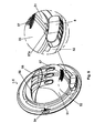
- Fig. 6 shows a detail of door 5 with drawer 8 extracted; the detail shows in particular that drawer 8 extends past the drain aperture 57a in order to collect the water.
- the collecting means may consist, more in general, of an extractable device, e.g. a plastic laminar support, on which a sponge or another absorbing material is secured.
- an extractable device e.g. a plastic laminar support, on which a sponge or another absorbing material is secured.
- the means that control the extraction of drawer 8 may comprise leaf springs or elastic means of a different kind, provided that they are adapted to extract the extractable device, e.g. drawer 8, from its housing when the door is opened.
- the motion of the extractable device may be of different kinds as well, i.e.: translational, rotational or rotational-translational.
- the extractable device may be a drawer 8 hinged to the door through one or several springs capable of causing a rotation of the door about a vertical axis, as shown in Fig. 7 .
- the elastic means that generate said rotation must be calibrated to extract the drawer as necessary for collecting dripping water: an excessive or insufficient opening action would place the drawer in a position which would not ensure an effective collection of dripping water.
- drawer 9 is hinged to the door in such a manner as to be rotatable about a horizontal axis.
- elastic means that cause the drawer to be extracted when the door is opened.
- control means essentially consisting of extraction means and locking means, the latter being adapted to keep the extractable device within its housing.
- the extraction means are essentially elastic means, e.g. springs, which push extractable device 8 out of housing 7.
- the locking means consist of a contact surface of the extractable device which engages with the cabinet as the extractable device closes when door 5 is closed.
- the extractable device is a drawer 8 entirely contained in frame 52 of door 5.
- the extractable device may be located in the inner surface of door 5, i.e. in an area not abutting against cabinet 2. In such a case, for the purpose of closing the extractable device again it will be possible to provide an appendix extending towards the door frame, thus abutting against cabinet 2 when door 5 is closed.
- control means controlling the motion of the extractable device comprise a peg which can translate freely within the frame and a system of levers and hinges adapted to transfer the motion of said peg to said extractable device.
- the peg As the door is closed, the peg is pushed into the frame and the system of levers and hinges transfers that motion to the extractable device, e.g. by rotating, translating, or rotating and translating it with movements similar to those described with reference to Figs. 1 to 8 .
Landscapes
- Engineering & Computer Science (AREA)
- Textile Engineering (AREA)
- Main Body Construction Of Washing Machines And Laundry Dryers (AREA)
- Saccharide Compounds (AREA)
- Seasonings (AREA)
Abstract
Description
- The present invention relates to a laundry washing machine according to the preamble of
claim 1. - The invention is applicable to the field of front-loading laundry washing machines (in particular washing and washing/drying machines) and faces the problem of water dripping from an open door.
- In front-loading washing machines, a door closes the load opening through which the laundry to be washed is loaded into a rotary drum arranged inside a wash tub. The inner portion of the door touches the wet laundry and the wash water, and therefore said portion is wet at the end of the washing.
- The Applicant has found that, when opening the door, water drops may fall onto the floor in front of the washing machine.
- This dripping is even more evident and troublesome in such washing machines as those known, for example, from patents
GB 1110375 GB 2260770 -
JP0671086 JP2001314695 - The main object of the present invention is therefore to reduce the dripping of water from the door of a front-loading washing machine when the latter is opened.
- This object is achieved through a laundry washing machine incorporating the features set out in the appended claims.
- In general terms, the present invention is based on the idea of fitting the door with suitable means for collecting the water dripping from it.
- Advantageously, said collecting means are controlled automatically as the door is opened, thus preventing any dripping from the door even if the user forgets to operate them.
- The collecting means are advantageously arranged within a housing obtained in the door frame, in particular in the lower half thereof, and are extracted through the effect of springs or other extraction means when the door is opened.
- Further objects and advantages of the present invention will become apparent from the following description and from the annexed drawings, wherein:
-
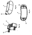
Fig. 1 shows a front-loading laundry washing machine according to the present invention; -
Fig. 2 shows a door of a front-loading laundry washing machine according to the present invention; -
Figs. 3a, 3b and 3c show three views of a water collecting drawer according to an embodiment of the present invention; -
Fig. 4 is a sectional view of the lower portion of a closed door according to the present invention; -
Fig. 5 is a sectional view of the lower portion of an open door according to the present invention; -
Fig. 6 shows an open door according to the present invention and a detail thereof; -
Figs. 7 and 8 show a door of a front-loading laundry washing machine according to variants of the present invention. - For clarity, in the present description the same reference numbers will be used for designating identical or equivalent items shown in the annexed drawings.
-
Fig. 1 shows a front-loadinglaundry washing machine 1. -
Machine 1 is of the type wherein the washing agent dispenser is arranged within the door. -
Machine 1 comprises acabinet 2 in which a wash tub is arranged in a known manner. Inside the latter, aperforated drum 3 rotates about a substantially horizontal axis. - The laundry to be washed is placed inside
drum 3 through a load opening 4 on the front side ofcabinet 2. - Load opening 4 is closed by a
door 5 comprising aninner surface 51 protruding from aframe 52 in the direction of the axis ofdrum 3. - When
door 5 is closed, the inner surface is inserted into the load opening and enters at least partly into the tub and intodrum 3.Frame 52 abuts against the cabinet, adjacent to load opening 4. - The rotation of
door 5 is ensured in a known manner by ahinge 53 which constrainsdoor 5 tocabinet 2. - In order to keep the door closed during the operation of the machine,
door 5 is fitted in a known manner with acatch 54 adapted to engage into ahook 21 ofcabinet 2. - In the preferred embodiment described below, the inner surface of
door 5 comprises awashing agent dispenser 55. -
Dispenser 55 hasupper apertures 56 for loading washing agents (e.g. softener, detergent...) andlower apertures 57 for draining a watery solution containing the washing agents. - When loading the washing machine, the user pours washing agents into respective compartments of the dispenser through
apertures 56, checking the levels of said washing agents throughtransparent inspection windows 58. - When the wash cycle is started, water is supplied into the dispenser in order to carry the washing agents into the tub (through lower apertures 57).
- At the end of the wash cycle, the inner surface of
door 5 has become wet, and a certain quantity of water may have remained withindispenser 55. - In order to collect water dripping from
door 5 when the latter is opened, according to the invention the lower half offrame 52 comprises collecting means adapted to collect water dripping frominner surface 51 or fromdispenser 55.Figs. 2 and6 show an example of embodiment of a door according to the invention. - In the lower half of
frame 52,door 5 comprises ahousing 7 which houses anextractable drawer 8. -
Drawer 8, some detailed views of which are shown inFigs. 3a, 3b and 3c , can contain water. However, when dripping onto a rigid surface such as the plastic surface ofdrawer 8, water may splash out of the drawer. - To prevent this drawback,
drawer 8 contains an absorbingmaterial 81 which can be easily removed in order to clean the drawer. - The term "absorbing material" refers to any material which can absorb water; in particular, the absorbing material may be a natural or synthetic absorbing sponge, e.g. made of reticular polyurethane, preferably having a density of about 30 - 35 Kg/m3. When using an absorbing sponge, it has been observed that the drops falling onto the sponge are not absorbed immediately; instead, they are only absorbed after a certain time, in the meantime they remain suspended on the top surface of the sponge.
- If the height of the sponge is the same as that of
drawer 8, the drops will move (or even bounce) and may fall onto the floor. To solve this problem, according to an embodiment of the invention the absorbing sponge is shallower thandrawer 8, so that an empty space of a few millimeters (preferably 5-10 mm) remains between the edge of the absorbing material and the edge ofdrawer 8. - Also advantageously, the sponge is so shaped as to increase the surface exposed to water drops; this is obtained through a concave face.
- According to an embodiment of the invention, the sponge has a concave face on one side and a flat face on the opposite side. This solution offers the double advantage that drop retention is increased thanks to a larger absorbing surface and that the sponge is polarized and cannot be installed incorrectly.
- As an alternative to using a single suitably shaped absorbing sponge, it is also possible to insert in
drawer 8 two overlaid sponge layers having different technical characteristics. An absorbing sponge (having either flat or concave faces) is laid on the bottom ofdrawer 8; a filtering sponge (e.g. filtered polyurethane) is then laid over said absorbing sponge. - The filtering sponge is characterized in that water will not dwell on its outer surface, but will flow through it immediately, without essentially bouncing or moving on the surface. For this reason, the filtering sponge can reach the top edge of
drawer 8, so that the absorbing sponge and the filtering sponge together essentially take up the whole volume ofdrawer 8. Advantageously, the filtering sponge and the absorbing sponge make up one piece, since the two materials are glued or co-moulded together and then cut to size. - Drawer 8 has two
housings 82 adapted to keep twocoil springs 83 in position. The opposite end ofsprings 83 engages into correspondingtapered surfaces 72 insidehousing 7. - When the door is closed,
frame 52 engages withcabinet 2, thus forcingdrawer 8 to stay withinhousing 7, as shown inFig. 4 . When the door is opened,springs 83translate drawer 8 out ofdoor 5, thus collecting water dripping from the latter, as shown inFig. 5 . - For the purpose of optimizing water collection,
housing 7 takes up a large portion (preferably more than 50%) of the depth offrame 52, thereby allowing to use adrawer 8 as big as possible. -
Dispenser 55 also has adrain aperture 57a located oninner surface 51 at a distance fromframe 52 that is shorter than the width of the portion ofdrawer 8 projecting fromhousing 7 when the door is open. - This position of
aperture 57a ensures that, when the door is opened, water that has possibly remained withindispenser 55 falls intodrawer 8, wherein it is collected. -
Fig. 6 shows a detail ofdoor 5 withdrawer 8 extracted; the detail shows in particular thatdrawer 8 extends past thedrain aperture 57a in order to collect the water. - The advantages of the present invention are apparent from the above description. In particular, it is clear that the presence of collecting means, in particular a drawer, in the lower half of the door allows to collect water dripping from the door when it is opened.
- The above-described preferred embodiment should be understood as a nonlimiting example of application of the present invention. As a matter of fact, it is clear that many changes may be made thereto by those skilled in the art without departing from the teachings of the present invention.
- For example, instead of comprising a drawer and a sponge, the collecting means may consist, more in general, of an extractable device, e.g. a plastic laminar support, on which a sponge or another absorbing material is secured.
- Likewise, the means that control the extraction of
drawer 8 may comprise leaf springs or elastic means of a different kind, provided that they are adapted to extract the extractable device,e.g. drawer 8, from its housing when the door is opened. - The motion of the extractable device may be of different kinds as well, i.e.: translational, rotational or rotational-translational.
- In a variant of the invention, the extractable device may be a
drawer 8 hinged to the door through one or several springs capable of causing a rotation of the door about a vertical axis, as shown inFig. 7 . According to this embodiment, the elastic means that generate said rotation must be calibrated to extract the drawer as necessary for collecting dripping water: an excessive or insufficient opening action would place the drawer in a position which would not ensure an effective collection of dripping water. - According to another embodiment, shown in
Fig. 8 , drawer 9 is hinged to the door in such a manner as to be rotatable about a horizontal axis. In this case as well, there are elastic means that cause the drawer to be extracted when the door is opened. - From the above-described examples of embodiment it is apparent that the motion of the extractable device is controlled by control means essentially consisting of extraction means and locking means, the latter being adapted to keep the extractable device within its housing.
- In the above-described examples, the extraction means are essentially elastic means, e.g. springs, which push
extractable device 8 out ofhousing 7. The locking means consist of a contact surface of the extractable device which engages with the cabinet as the extractable device closes whendoor 5 is closed. In the examples ofFigs. 1 to 8 , the extractable device is adrawer 8 entirely contained inframe 52 ofdoor 5. Alternatively, the extractable device may be located in the inner surface ofdoor 5, i.e. in an area not abutting againstcabinet 2. In such a case, for the purpose of closing the extractable device again it will be possible to provide an appendix extending towards the door frame, thus abutting againstcabinet 2 whendoor 5 is closed. - According to a further embodiment, the control means controlling the motion of the extractable device comprise a peg which can translate freely within the frame and a system of levers and hinges adapted to transfer the motion of said peg to said extractable device. As the door is closed, the peg is pushed into the frame and the system of levers and hinges transfers that motion to the extractable device, e.g. by rotating, translating, or rotating and translating it with movements similar to those described with reference to
Figs. 1 to 8 .
Claims (15)
- Front-loading laundry washing machine wherein a cabinet (2) has a load opening (3) which can be closed by means of a door (5) constrained to said cabinet (2), said door (5) comprising an inner surface (51) adapted to be at least partly inserted into said opening (3) and a frame (52) adapted to engage with said cabinet (2), characterized in that said door (5) comprises collecting means arranged in the lower half of said door (5) for collecting water dripping from said door when the latter is opened, and in that said collecting means comprise an extractable device (8).
- Laundry washing machine according to claim 1, wherein said extractable device (8) is a drawer.
- Laundry washing machine according to claim 1 or 2, characterized in that said collecting means comprise control means adapted to control the movement of said extractable device, said control means being at least partially located on said frame (52) and comprising in particular elastic means (83) adapted to extract said extractable device from a housing (7) obtained in said frame (52).
- Laundry washing machine according to claim 3, characterized in that said elastic means (83) are adapted to translate said extractable device (8) out of said housing (7).
- Laundry washing machine according to claim 3, characterized in that said extractable device (8) is hinged to said door (5) and that said elastic means are adapted to generate a rotation of said extractable device (8) about a horizontal axis or about a vertical axis.
- Laundry washing machine according to any of claims 3 to 5, characterized in that said control means comprise a surface of said extractable device (8) which is adapted to engage with said cabinet (2).
- Laundry washing machine according to any of claims 3 to 5, characterized in that said control means comprise a peg which can translate freely within said frame (52) and a system of levers and hinges adapted to transfer the motion of said peg to said extractable device (8).
- Laundry washing machine according to any of the preceding claims, characterized in that said door (5) comprises a washing agent dispenser (55).
- Laundry washing machine according to claim 8, when dependent on any of claims 3 to 7, characterized in that said dispenser (55) comprises a drain aperture (57a) located on the bottom of said dispenser (55) at a distance from said frame (52) shorter than the width of the portion of said drawer (8) projecting over said housing (7) when said door (5) is open.
- Laundry washing machine according to any of the preceding claims, characterized in that said collecting means are controlled automatically as said door is opened.
- Laundry washing machine according to any of the preceding claims, characterized in that said collecting means comprise an absorbing material (81), said absorbing material (81) comprising in particular an absorbing sponge, preferably made of reticular polyurethane.
- Laundry washing machine according to claim 11, characterized in that said sponge is shallower than said drawer (8).
- Laundry washing machine according to claim 11 or 12, characterized in that said sponge has a concave face, said sponge having in particular a flat face opposite to said concave face.
- Laundry washing machine according to any of claims 11 to 13, characterized in that said collecting means comprise an absorbing sponge for retaining the water and a filtering sponge, preferably made of filtered polyurethane, laid over said absorbing sponge for percolating the water to the absorbing sponge, in particular said absorbing sponge and said filtering sponge essentially taking up the whole volume of said extractable device.
- Door for a front-loading laundry washing machine, comprising an inner surface (51) projecting out relative to a frame (52), characterized by comprising collecting means located in the lower half of said door (52) for collecting water dripping from said door when the latter is opened, the collecting means comprising an extractable device (8), and by comprising a housing (7) for the extractable device (8) and control means adapted to control the movement of said extractable device, said control means being at least partly located on said frame (52).
Applications Claiming Priority (2)
| Application Number | Priority Date | Filing Date | Title |
|---|---|---|---|
| IT000738A ITTO20060738A1 (en) | 2006-10-13 | 2006-10-13 | WASHING MACHINE WITH FRONTAL CHARGE |
| PCT/IB2007/003035 WO2008044131A2 (en) | 2006-10-13 | 2007-10-12 | Front-loading laundry washing machine |
Publications (2)
| Publication Number | Publication Date |
|---|---|
| EP2094892A2 EP2094892A2 (en) | 2009-09-02 |
| EP2094892B1 true EP2094892B1 (en) | 2011-03-30 |
Family
ID=39203158
Family Applications (1)
| Application Number | Title | Priority Date | Filing Date |
|---|---|---|---|
| EP07825341A Active EP2094892B1 (en) | 2006-10-13 | 2007-10-12 | Front-loading laundry washing machine |
Country Status (5)
| Country | Link |
|---|---|
| EP (1) | EP2094892B1 (en) |
| AT (1) | ATE503879T1 (en) |
| DE (1) | DE602007013607D1 (en) |
| IT (1) | ITTO20060738A1 (en) |
| WO (1) | WO2008044131A2 (en) |
Family Cites Families (3)
| Publication number | Priority date | Publication date | Assignee | Title |
|---|---|---|---|---|
| IT1256272B (en) * | 1991-10-22 | 1995-11-29 | Zanussi Elettrodomestici | WASHING MACHINE WITH DETERGENT CONTAINER RECOVERED IN THE PORTHOLE |
| JPH0671086A (en) * | 1992-08-28 | 1994-03-15 | Sanyo Electric Co Ltd | Drum-type washing dryer |
| JP2001314695A (en) * | 2000-05-08 | 2001-11-13 | Matsushita Electric Ind Co Ltd | Washing machine |
-
2006
- 2006-10-13 IT IT000738A patent/ITTO20060738A1/en unknown
-
2007
- 2007-10-12 AT AT07825341T patent/ATE503879T1/en not_active IP Right Cessation
- 2007-10-12 DE DE602007013607T patent/DE602007013607D1/en active Active
- 2007-10-12 WO PCT/IB2007/003035 patent/WO2008044131A2/en active Application Filing
- 2007-10-12 EP EP07825341A patent/EP2094892B1/en active Active
Also Published As
| Publication number | Publication date |
|---|---|
| WO2008044131A3 (en) | 2008-06-12 |
| EP2094892A2 (en) | 2009-09-02 |
| ITTO20060738A1 (en) | 2008-04-14 |
| DE602007013607D1 (en) | 2011-05-12 |
| WO2008044131A2 (en) | 2008-04-17 |
| ATE503879T1 (en) | 2011-04-15 |
Similar Documents
| Publication | Publication Date | Title |
|---|---|---|
| US9309617B2 (en) | Home appliance having detergent compartment | |
| US9637855B2 (en) | Front loading laundry machine having bellows | |
| EP2602378B1 (en) | A front-loading laundry washing machine for household use, in particular a washing or washing/drying machine | |
| CN104727058A (en) | Washing machine | |
| US10422070B2 (en) | Laundry treating appliance and dispenser | |
| US11708657B2 (en) | Laundry treating appliance and dispenser | |
| EP2425047B1 (en) | Front-loading household washing machine, in particular a laundry washing or washing/drying machine | |
| CN111356803B (en) | Washing cover and washing processing equipment with same | |
| EP2094892B1 (en) | Front-loading laundry washing machine | |
| EP2455538A1 (en) | A clothes dryer comprising a container for collecting the condensed water and container thereof | |
| CN106256945B (en) | Washing machine capable of separately washing | |
| KR20170096321A (en) | Apparatus for injecting liquid additive in washing machine | |
| EP2977499B1 (en) | Laundry washing machine | |
| WO2016201906A1 (en) | Washing machine having separate washing arrangements | |
| KR20110013060A (en) | A laundry treatment machine | |
| KR100671895B1 (en) | System for opening and closing door of a drum-type washing machine downward and upward | |
| KR102247628B1 (en) | cleanable washing machine | |
| CN111373089A (en) | Household appliance | |
| KR101371279B1 (en) | Apparatus for preventing descent and floating by opening and closing door handle of dish washer | |
| KR200274912Y1 (en) | Washer of athletic shoes | |
| EP2633115A1 (en) | A front-loading laundry washing machine for household use, in particular a washing or washing/drying machine | |
| KR101422004B1 (en) | Device for treating laundry | |
| KR0115046Y1 (en) | A custody device of washing | |
| KR100479094B1 (en) | A washing machine | |
| KR20220112503A (en) | Washing machine |
Legal Events
| Date | Code | Title | Description |
|---|---|---|---|
| PUAI | Public reference made under article 153(3) epc to a published international application that has entered the european phase |
Free format text: ORIGINAL CODE: 0009012 |
|
| 17P | Request for examination filed |
Effective date: 20090420 |
|
| AK | Designated contracting states |
Kind code of ref document: A2 Designated state(s): AT BE BG CH CY CZ DE DK EE ES FI FR GB GR HU IE IS IT LI LT LU LV MC MT NL PL PT RO SE SI SK TR |
|
| DAX | Request for extension of the european patent (deleted) | ||
| 17Q | First examination report despatched |
Effective date: 20100216 |
|
| GRAP | Despatch of communication of intention to grant a patent |
Free format text: ORIGINAL CODE: EPIDOSNIGR1 |
|
| GRAS | Grant fee paid |
Free format text: ORIGINAL CODE: EPIDOSNIGR3 |
|
| GRAA | (expected) grant |
Free format text: ORIGINAL CODE: 0009210 |
|
| AK | Designated contracting states |
Kind code of ref document: B1 Designated state(s): AT BE BG CH CY CZ DE DK EE ES FI FR GB GR HU IE IS IT LI LT LU LV MC MT NL PL PT RO SE SI SK TR |
|
| REG | Reference to a national code |
Ref country code: GB Ref legal event code: FG4D |
|
| REG | Reference to a national code |
Ref country code: CH Ref legal event code: EP |
|
| REG | Reference to a national code |
Ref country code: IE Ref legal event code: FG4D |
|
| REF | Corresponds to: |
Ref document number: 602007013607 Country of ref document: DE Date of ref document: 20110512 Kind code of ref document: P |
|
| REG | Reference to a national code |
Ref country code: DE Ref legal event code: R096 Ref document number: 602007013607 Country of ref document: DE Effective date: 20110512 |
|
| REG | Reference to a national code |
Ref country code: NL Ref legal event code: VDEP Effective date: 20110330 |
|
| PG25 | Lapsed in a contracting state [announced via postgrant information from national office to epo] |
Ref country code: GR Free format text: LAPSE BECAUSE OF FAILURE TO SUBMIT A TRANSLATION OF THE DESCRIPTION OR TO PAY THE FEE WITHIN THE PRESCRIBED TIME-LIMIT Effective date: 20110701 Ref country code: SE Free format text: LAPSE BECAUSE OF FAILURE TO SUBMIT A TRANSLATION OF THE DESCRIPTION OR TO PAY THE FEE WITHIN THE PRESCRIBED TIME-LIMIT Effective date: 20110330 Ref country code: LT Free format text: LAPSE BECAUSE OF FAILURE TO SUBMIT A TRANSLATION OF THE DESCRIPTION OR TO PAY THE FEE WITHIN THE PRESCRIBED TIME-LIMIT Effective date: 20110330 Ref country code: LV Free format text: LAPSE BECAUSE OF FAILURE TO SUBMIT A TRANSLATION OF THE DESCRIPTION OR TO PAY THE FEE WITHIN THE PRESCRIBED TIME-LIMIT Effective date: 20110330 |
|
| LTIE | Lt: invalidation of european patent or patent extension |
Effective date: 20110330 |
|
| PG25 | Lapsed in a contracting state [announced via postgrant information from national office to epo] |
Ref country code: AT Free format text: LAPSE BECAUSE OF FAILURE TO SUBMIT A TRANSLATION OF THE DESCRIPTION OR TO PAY THE FEE WITHIN THE PRESCRIBED TIME-LIMIT Effective date: 20110330 Ref country code: SI Free format text: LAPSE BECAUSE OF FAILURE TO SUBMIT A TRANSLATION OF THE DESCRIPTION OR TO PAY THE FEE WITHIN THE PRESCRIBED TIME-LIMIT Effective date: 20110330 Ref country code: CY Free format text: LAPSE BECAUSE OF FAILURE TO SUBMIT A TRANSLATION OF THE DESCRIPTION OR TO PAY THE FEE WITHIN THE PRESCRIBED TIME-LIMIT Effective date: 20110330 Ref country code: FI Free format text: LAPSE BECAUSE OF FAILURE TO SUBMIT A TRANSLATION OF THE DESCRIPTION OR TO PAY THE FEE WITHIN THE PRESCRIBED TIME-LIMIT Effective date: 20110330 |
|
| PG25 | Lapsed in a contracting state [announced via postgrant information from national office to epo] |
Ref country code: BE Free format text: LAPSE BECAUSE OF FAILURE TO SUBMIT A TRANSLATION OF THE DESCRIPTION OR TO PAY THE FEE WITHIN THE PRESCRIBED TIME-LIMIT Effective date: 20110330 |
|
| PG25 | Lapsed in a contracting state [announced via postgrant information from national office to epo] |
Ref country code: PT Free format text: LAPSE BECAUSE OF FAILURE TO SUBMIT A TRANSLATION OF THE DESCRIPTION OR TO PAY THE FEE WITHIN THE PRESCRIBED TIME-LIMIT Effective date: 20110801 Ref country code: EE Free format text: LAPSE BECAUSE OF FAILURE TO SUBMIT A TRANSLATION OF THE DESCRIPTION OR TO PAY THE FEE WITHIN THE PRESCRIBED TIME-LIMIT Effective date: 20110330 |
|
| PG25 | Lapsed in a contracting state [announced via postgrant information from national office to epo] |
Ref country code: CZ Free format text: LAPSE BECAUSE OF FAILURE TO SUBMIT A TRANSLATION OF THE DESCRIPTION OR TO PAY THE FEE WITHIN THE PRESCRIBED TIME-LIMIT Effective date: 20110330 Ref country code: SK Free format text: LAPSE BECAUSE OF FAILURE TO SUBMIT A TRANSLATION OF THE DESCRIPTION OR TO PAY THE FEE WITHIN THE PRESCRIBED TIME-LIMIT Effective date: 20110330 Ref country code: RO Free format text: LAPSE BECAUSE OF FAILURE TO SUBMIT A TRANSLATION OF THE DESCRIPTION OR TO PAY THE FEE WITHIN THE PRESCRIBED TIME-LIMIT Effective date: 20110330 Ref country code: ES Free format text: LAPSE BECAUSE OF FAILURE TO SUBMIT A TRANSLATION OF THE DESCRIPTION OR TO PAY THE FEE WITHIN THE PRESCRIBED TIME-LIMIT Effective date: 20110711 Ref country code: IS Free format text: LAPSE BECAUSE OF FAILURE TO SUBMIT A TRANSLATION OF THE DESCRIPTION OR TO PAY THE FEE WITHIN THE PRESCRIBED TIME-LIMIT Effective date: 20110730 |
|
| PG25 | Lapsed in a contracting state [announced via postgrant information from national office to epo] |
Ref country code: NL Free format text: LAPSE BECAUSE OF FAILURE TO SUBMIT A TRANSLATION OF THE DESCRIPTION OR TO PAY THE FEE WITHIN THE PRESCRIBED TIME-LIMIT Effective date: 20110330 |
|
| PLBE | No opposition filed within time limit |
Free format text: ORIGINAL CODE: 0009261 |
|
| STAA | Information on the status of an ep patent application or granted ep patent |
Free format text: STATUS: NO OPPOSITION FILED WITHIN TIME LIMIT |
|
| PG25 | Lapsed in a contracting state [announced via postgrant information from national office to epo] |
Ref country code: PL Free format text: LAPSE BECAUSE OF FAILURE TO SUBMIT A TRANSLATION OF THE DESCRIPTION OR TO PAY THE FEE WITHIN THE PRESCRIBED TIME-LIMIT Effective date: 20110330 Ref country code: DK Free format text: LAPSE BECAUSE OF FAILURE TO SUBMIT A TRANSLATION OF THE DESCRIPTION OR TO PAY THE FEE WITHIN THE PRESCRIBED TIME-LIMIT Effective date: 20110330 |
|
| 26N | No opposition filed |
Effective date: 20120102 |
|
| REG | Reference to a national code |
Ref country code: DE Ref legal event code: R097 Ref document number: 602007013607 Country of ref document: DE Effective date: 20120102 |
|
| PG25 | Lapsed in a contracting state [announced via postgrant information from national office to epo] |
Ref country code: MC Free format text: LAPSE BECAUSE OF NON-PAYMENT OF DUE FEES Effective date: 20111031 |
|
| REG | Reference to a national code |
Ref country code: CH Ref legal event code: PL |
|
| PG25 | Lapsed in a contracting state [announced via postgrant information from national office to epo] |
Ref country code: LI Free format text: LAPSE BECAUSE OF NON-PAYMENT OF DUE FEES Effective date: 20111031 Ref country code: CH Free format text: LAPSE BECAUSE OF NON-PAYMENT OF DUE FEES Effective date: 20111031 |
|
| REG | Reference to a national code |
Ref country code: IE Ref legal event code: MM4A |
|
| PG25 | Lapsed in a contracting state [announced via postgrant information from national office to epo] |
Ref country code: IE Free format text: LAPSE BECAUSE OF NON-PAYMENT OF DUE FEES Effective date: 20111012 |
|
| PG25 | Lapsed in a contracting state [announced via postgrant information from national office to epo] |
Ref country code: MT Free format text: LAPSE BECAUSE OF FAILURE TO SUBMIT A TRANSLATION OF THE DESCRIPTION OR TO PAY THE FEE WITHIN THE PRESCRIBED TIME-LIMIT Effective date: 20110330 |
|
| PG25 | Lapsed in a contracting state [announced via postgrant information from national office to epo] |
Ref country code: LU Free format text: LAPSE BECAUSE OF NON-PAYMENT OF DUE FEES Effective date: 20111012 |
|
| GBPC | Gb: european patent ceased through non-payment of renewal fee |
Effective date: 20121012 |
|
| PG25 | Lapsed in a contracting state [announced via postgrant information from national office to epo] |
Ref country code: BG Free format text: LAPSE BECAUSE OF FAILURE TO SUBMIT A TRANSLATION OF THE DESCRIPTION OR TO PAY THE FEE WITHIN THE PRESCRIBED TIME-LIMIT Effective date: 20110630 |
|
| PG25 | Lapsed in a contracting state [announced via postgrant information from national office to epo] |
Ref country code: GB Free format text: LAPSE BECAUSE OF NON-PAYMENT OF DUE FEES Effective date: 20121012 |
|
| PG25 | Lapsed in a contracting state [announced via postgrant information from national office to epo] |
Ref country code: TR Free format text: LAPSE BECAUSE OF FAILURE TO SUBMIT A TRANSLATION OF THE DESCRIPTION OR TO PAY THE FEE WITHIN THE PRESCRIBED TIME-LIMIT Effective date: 20110330 |
|
| PG25 | Lapsed in a contracting state [announced via postgrant information from national office to epo] |
Ref country code: HU Free format text: LAPSE BECAUSE OF FAILURE TO SUBMIT A TRANSLATION OF THE DESCRIPTION OR TO PAY THE FEE WITHIN THE PRESCRIBED TIME-LIMIT Effective date: 20110330 |
|
| REG | Reference to a national code |
Ref country code: FR Ref legal event code: PLFP Year of fee payment: 9 |
|
| REG | Reference to a national code |
Ref country code: FR Ref legal event code: PLFP Year of fee payment: 10 |
|
| REG | Reference to a national code |
Ref country code: FR Ref legal event code: PLFP Year of fee payment: 11 |
|
| REG | Reference to a national code |
Ref country code: FR Ref legal event code: PLFP Year of fee payment: 12 |
|
| PGFP | Annual fee paid to national office [announced via postgrant information from national office to epo] |
Ref country code: IT Payment date: 20210910 Year of fee payment: 15 Ref country code: FR Payment date: 20210913 Year of fee payment: 15 |
|
| P01 | Opt-out of the competence of the unified patent court (upc) registered |
Effective date: 20230522 |
|
| PG25 | Lapsed in a contracting state [announced via postgrant information from national office to epo] |
Ref country code: FR Free format text: LAPSE BECAUSE OF NON-PAYMENT OF DUE FEES Effective date: 20221031 |
|
| PG25 | Lapsed in a contracting state [announced via postgrant information from national office to epo] |
Ref country code: IT Free format text: LAPSE BECAUSE OF NON-PAYMENT OF DUE FEES Effective date: 20221012 |
|
| REG | Reference to a national code |
Ref country code: DE Ref legal event code: R082 Ref document number: 602007013607 Country of ref document: DE Ref country code: DE Ref legal event code: R081 Ref document number: 602007013607 Country of ref document: DE Owner name: WHIRLPOOL EMEA S.R.L., IT Free format text: FORMER OWNER: INDESIT COMPANY S.P.A., FABRIANO, ANCONA, IT |
|
| PGFP | Annual fee paid to national office [announced via postgrant information from national office to epo] |
Ref country code: DE Payment date: 20231027 Year of fee payment: 17 |