EP2094594B1 - Device for gluing a tail cant of a roll and product roll - Google Patents
Device for gluing a tail cant of a roll and product roll Download PDFInfo
- Publication number
- EP2094594B1 EP2094594B1 EP06818855.6A EP06818855A EP2094594B1 EP 2094594 B1 EP2094594 B1 EP 2094594B1 EP 06818855 A EP06818855 A EP 06818855A EP 2094594 B1 EP2094594 B1 EP 2094594B1
- Authority
- EP
- European Patent Office
- Prior art keywords
- blade
- roll
- glue
- tail
- glue application
- Prior art date
- Legal status (The legal status is an assumption and is not a legal conclusion. Google has not performed a legal analysis and makes no representation as to the accuracy of the status listed.)
- Active
Links
Images









Classifications
-
- B—PERFORMING OPERATIONS; TRANSPORTING
- B65—CONVEYING; PACKING; STORING; HANDLING THIN OR FILAMENTARY MATERIAL
- B65H—HANDLING THIN OR FILAMENTARY MATERIAL, e.g. SHEETS, WEBS, CABLES
- B65H19/00—Changing the web roll
- B65H19/22—Changing the web roll in winding mechanisms or in connection with winding operations
- B65H19/29—Securing the trailing end of the wound web to the web roll
-
- B—PERFORMING OPERATIONS; TRANSPORTING
- B05—SPRAYING OR ATOMISING IN GENERAL; APPLYING FLUENT MATERIALS TO SURFACES, IN GENERAL
- B05C—APPARATUS FOR APPLYING FLUENT MATERIALS TO SURFACES, IN GENERAL
- B05C1/00—Apparatus in which liquid or other fluent material is applied to the surface of the work by contact with a member carrying the liquid or other fluent material, e.g. a porous member loaded with a liquid to be applied as a coating
- B05C1/02—Apparatus in which liquid or other fluent material is applied to the surface of the work by contact with a member carrying the liquid or other fluent material, e.g. a porous member loaded with a liquid to be applied as a coating for applying liquid or other fluent material to separate articles
- B05C1/027—Apparatus in which liquid or other fluent material is applied to the surface of the work by contact with a member carrying the liquid or other fluent material, e.g. a porous member loaded with a liquid to be applied as a coating for applying liquid or other fluent material to separate articles only at particular parts of the articles
-
- B—PERFORMING OPERATIONS; TRANSPORTING
- B65—CONVEYING; PACKING; STORING; HANDLING THIN OR FILAMENTARY MATERIAL
- B65H—HANDLING THIN OR FILAMENTARY MATERIAL, e.g. SHEETS, WEBS, CABLES
- B65H2301/00—Handling processes for sheets or webs
- B65H2301/40—Type of handling process
- B65H2301/41—Winding, unwinding
- B65H2301/414—Winding
- B65H2301/4144—Finishing winding process
- B65H2301/41441—Finishing winding process and blocking outer layers against falling apart
- B65H2301/41442—Specified by the sealing medium sealing used
- B65H2301/414421—Glue or hot-melt
-
- B—PERFORMING OPERATIONS; TRANSPORTING
- B65—CONVEYING; PACKING; STORING; HANDLING THIN OR FILAMENTARY MATERIAL
- B65H—HANDLING THIN OR FILAMENTARY MATERIAL, e.g. SHEETS, WEBS, CABLES
- B65H2301/00—Handling processes for sheets or webs
- B65H2301/40—Type of handling process
- B65H2301/41—Winding, unwinding
- B65H2301/414—Winding
- B65H2301/4144—Finishing winding process
- B65H2301/41441—Finishing winding process and blocking outer layers against falling apart
- B65H2301/41443—Specified by the place to where the sealing medium is applied
- B65H2301/414433—Specified by the place to where the sealing medium is applied onto the roll
-
- B—PERFORMING OPERATIONS; TRANSPORTING
- B65—CONVEYING; PACKING; STORING; HANDLING THIN OR FILAMENTARY MATERIAL
- B65H—HANDLING THIN OR FILAMENTARY MATERIAL, e.g. SHEETS, WEBS, CABLES
- B65H2301/00—Handling processes for sheets or webs
- B65H2301/40—Type of handling process
- B65H2301/41—Winding, unwinding
- B65H2301/414—Winding
- B65H2301/4144—Finishing winding process
- B65H2301/41441—Finishing winding process and blocking outer layers against falling apart
- B65H2301/41444—Specified by process phase during which sealing /securing is performed
- B65H2301/414446—Sealing or securing in a separate following station
-
- Y—GENERAL TAGGING OF NEW TECHNOLOGICAL DEVELOPMENTS; GENERAL TAGGING OF CROSS-SECTIONAL TECHNOLOGIES SPANNING OVER SEVERAL SECTIONS OF THE IPC; TECHNICAL SUBJECTS COVERED BY FORMER USPC CROSS-REFERENCE ART COLLECTIONS [XRACs] AND DIGESTS
- Y10—TECHNICAL SUBJECTS COVERED BY FORMER USPC
- Y10T—TECHNICAL SUBJECTS COVERED BY FORMER US CLASSIFICATION
- Y10T428/00—Stock material or miscellaneous articles
- Y10T428/24—Structurally defined web or sheet [e.g., overall dimension, etc.]
- Y10T428/24174—Structurally defined web or sheet [e.g., overall dimension, etc.] including sheet or component perpendicular to plane of web or sheet
- Y10T428/24182—Inward from edge of web or sheet
Definitions
- a method or an apparatus for securing the tail or outer terminal convolution of a toilet tissue cant or similar roll product to the convolution immediately adjacent the tail is known from US 4,026,752 .
- the tail of the roll product is secured by means of adhesive, and the method includes the step of ejecting a predetermined quantity of adhesive directly onto the subjacent convolution of the roll product while the tail is unwound there from.
- the adhesive is distributed along the length of the cant at spaced apart locations adapted to underlie the rewound tail, thereby allowing the tail to be adhesively secured to the cant.
- Each adhesive applicator module includes a plurality of dispensing nozzles operative to eject a measured quantity of adhesive onto a cant underlying the same.
- WO 95/15902 describes a device for gluing the tail end of a reel of wound web material comprising a dispenser of glue for applying the glue to the reel and means for rewinding the tail end after the glue has been applied.
- a dispenser of glue for applying the glue to the reel and means for rewinding the tail end after the glue has been applied.
- the glue Applied to the tail end is the glue by a transverse bar as a continuous glue strip and upwardly the bar is provided with a concave surface which is in practice a longitudinal channel extending substantially along the whole length of the bar.
- a device for gluing a tail cant of a roll or log of wound web material having the features in the preamble of claim 1 is known by JP-A-2006-131400 .
- a device for gluing a tail cant or tail sheet of a roll or log of wound web material comprising a support for the roll or log, a dispenser of glue, at least one movable blade on which a glue-application-edge is provided, said blade being oriented parallel to the roll or log longitudinal axis (cross machine direction - CD).
- the glue application edge of the blade has an interrupted glue application surface.
- portions of the glue application surface are lengthwise oriented in a direction perpendicular to the roll or log longitudinal axis (machine direction MD).
- the larger length of the portions of the glue application surface also contributes to a higher gluing effect in CD and a more easy tearing off in MD is possibly without destroying the underlying sheet, because tearing off starts with a lower amount of glued areas because the glue portions on the tail sheet are extending in MD.
- the device according to the invention may comprise at least one movable blade. Although using one movable blade is preferred, it is also possible that such a device may comprise two, three or even more of these movable blades.
- Tail sealing of such paper product rolls or logs is necessary especially for keeping the form of the roll in handling (conveying) of the rolls during manufacture and for packaging the rolls. Thereafter tail sealing would not be necessary.
- During conveying forces are applied to the roll and the tail sheet in cross machine direction CD, i.e. parallel to the longitudinal axis of the roll.
- sufficient tail sealing force against tearing off is achieved allowing simultaneously a simple and easy tearing off in machine direction MD, i.e. perpendicular to the longitudinal axis of the roll when separating the tail sheet of the roll without destroying underlying sheets.
- the glue application edge of the blade is a lengthwise discontinuous edge and preferably the glue application edge of the blade provides in longitudinal direction merlons and crenels, said merlons forming the glue application surface.
- An essential point is the choice for the amount of glue application surface being for instance between 25% and 90% of the surface glue application edge of the blade, preferably between 30% and 70% and most preferably between 50% and 60%.
- the glue application surface of the blade is formed by portions of the blade being oriented lengthwise substantially perpendicular to the longitudinal extension of the blade and extend beyond the widths of the blade.
- portions of the glue application surface are lengthwise oriented in a direction perpendicular to the roll or log longitudinal axis (MD).
- the portions forming the glue application surface are integral parts of the blade or, on the other hand, the portions forming the glue application surface are parts fastened in a distanced manner to the blade.
- a tail sheet can be glued to underlying sheet or sheets.
- the longitudinal extension of the glue portions is perpendicular to the longitudinal axis of the roll.
- a glue pattern is present in form of a row of separated glue portions.
- the ratio between length and width of the respective glue portions is at least 2:1, especially at least 3:1.
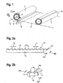
- Fig. 1 illustrates in a diagrammatic manner a roll or log 1 conveyed in direction of the arrow 2 on a conveying surface 3.
- the blade 5 is movable forward and backwards according to an arrow 8.
- the longitudinal axis of the roll 1 is marked in Fig. 1 as having the reference letter a.
- the glue application blade illustrated diagrammatically in Fig. 2a has a glue application edge 10 having a glue application surface formed in its entirety by surface portions 11a being crenels interrupted by merlons 12.
- the portions 11a are lengthwise oriented in CD and have a length Ii and the merlons 12 have a length I2.
- the blade itself has a width W1.
- Fig. 2b shows an embodiment of the blade 5 according to the invention.
- glue application portions lib These are oriented in MD. These portions have a length I3 and are in CD in a distance of d and a width W2.
- the portions 11a of the glue application surface is oriented in CD and the portions lib according to Fig. 2b are oriented in MD, which leads to a glue application pattern result illustrated in Fig. 3a and Fig. 3b .
- FIGs. 4a to 4f another mode of glue application and tail sealing is illustrated step by step from Fig. 4a to Fig. 4f .
- This device shows an upper conveyer belt 13 as an endless belt and a lower conveyer belt 14 as an endless belt. Between these conveyer belts a roll 1 is conveyed in the direction of the arrow 15, since the conveyer belts are driven in the same direction. The tail or tail sheet 7 is sucked into the gap 4 and the blade 5 is retracted within the glue chamber 6. Downstream of the gap 4 a stationary support 3 is illustrated, wherein a pressure roller 16 is provided. This condition is illustrated in Fig. 4a . In the next step according to Fig.
- the blade 5 is extended in an upper position and glue is applied here not to the tail sheet but on the circumference of the roll 1 where the tail sheet ends. Thereafter, the blade 5 is retracted and the roll 1 is furthermore transferred to the right side on the support 3. This is illustrated in Fig. 4c .
- Fig. 4d a position is illustrated where the roll 1 is provided between the upper conveyer belt 13 and the pressure roller 16, which is then rotated such that the roll 1 is rotated between the conveyer belt 13 and the pressure roller 16.
- Fig. 4d and 4e In Fig. 4e is visible the tail sheet already fastened by gluing and by the pressure roller the bonding effect is increased. Then the rotation of the pressure roller is stopped and the roll 1 is delivered in the direction of the arrow 17.
- the applied glue pattern is marked by the reference number G.
- Fig. 5a shows the whole blade and Fig. 5b an enlarged part of the blade 1 with the contour of the glue application edge.
- the thickness w1 of the blade is 2.1 mm
- the merlon 11 has a length l 1 of 10 mm and the crenel 12 a length l 2 of 5 mm.
- the glue application area which means the sum of all portions of the glue application surface, is 66% of the whole glue application edge when the glue application edge is not interrupted or discontinuous.
- Tail seal blade 2 is illustrated in Fig. 6a, 6b, 6c and 6d .
- the Figs. 6b and 6d show the glue application surface having a groove so that the glue application surface is reduced. This is a possibility being not considered in connection with the tests.
- the glue application area here is 50% and the thickness w 1 is also 2,1 mm.
- the length l 1 is the same as the length l 2 being 5 mm.
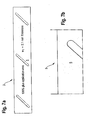
- Tail seal blade 3 is illustrated in Fig. 7a and Fig. 7b .
- the glue application area is 100% and the thickness w 1 2,1 mm. This blade is used for comparison only, because this complies with the prior art.
- Tail seal blade 4 as illustrated in Figs. 8a and 8b uses inserts 11b as illustrated in Fig. 2b .
- the ame is for tail seal blade 5 illustrated in Figs. 9a and 9b .
- the glue application area is 66%.
- the thickness w 2 is 2 mm and the width l 3 10 mm.
- the distance between the inserts 11b(d) is 15 mm.
- Tail seal blade 5 according to Figs. 9a and 9b has a glue application area of 33%.
- the thickness w 2 is 2 mm and the widths l 3 is 10 mm.
- the distance d between the inserts 11b is 30 mm.
- tail seal blade 6 according to Figs. 10a and 10b shows a blade 5 according to the prior art without discontinuous glue application surface. Therefore, the glue application area is 100% and the thickness w 1 is 2,1 mm.
- Tail seal blade 7 shows another crenellated configuration of the glue application edge, where the crenels 12 have the same lengths l 2 of 20 mm.
- the lengths l 1 of the merlons 11 is different being 10 mm and 40 mm.
- the glue application area is 50% and the thickness of the blade is 2,1 mm.
- tail seal blade 8 shows a blade according to the prior art without discontinuous glue application edge. Therefore, the glue application area is 100% but the thickness w 1 now is 2,8 mm. This seal blade 8 is illustrated in Figs. 12a and 12b .
- Tables 1 and 2 illustrate the variants 1 to 4.
- Variant A Tear off behaviour
- B Tear off behaviour
- C Penetration behaviour through top ply
- E Adhesion to ply underneath
- F Penetration behaviour to ply underneath
- G Optical appearance
- Table 2 demonstrates that those variants 2, 3 and 4 according to the invention (using blades 4, 5 and 7) result in an improved product performance in terms of optical appearance, adhesion and penetration compared with variant 1 according to the prior art (using blade 8).
- product-rolls obtained from variants 2, 3 and 4 are characterized by an improved tear-off strength in CD than in MD compared to product-rolls according to the prior art (variant 1) thereby leading to a very convenient product for the consumer in view of tearing off the first sheet.
- Table 3 shows the weighting factor with respect to the consumers and the production. Consumer Production Tear off MD TS 25% 75% Tear off CD TS 75% 25% Penetration TS 25% 75% Optical App. TS 25% 75% Adhesion AP 75% 25% Penetration AP 75% 25% Optical App. Ap 75% 25%
Landscapes
- Coating Apparatus (AREA)
- Sanitary Thin Papers (AREA)
- Adhesive Tapes (AREA)
- Application Of Or Painting With Fluid Materials (AREA)
Description
- In paper products wound to a roll or reel or log using tissue-paper or non-woven material, being products as toilet papers or kitchen towels the trailing end or trailing cant of the roll or log is glued to an underlying web of the roll or log. "Log" is a material web wound to a reel in a rewinder, said log finally being cut into a plurality of part-lengths for final roll as toilet paper roll or kitchen towel roll. For using the first sheets of the roll the first sheet glued to an underlying sheet has to be torn off.
- From
US 2005/0199761 A1 andUS 2005/0199759 A1 it is known to control the strength and location of bonds by controlling the penetration of adhesive into the tissue. This stands in connection with easy starting rolls of perforated tissue product which have a reduced tendency to ply separate. Such rolls are formed with an adhesively secured doubled over tail tap folded against the roll. - A method or an apparatus for securing the tail or outer terminal convolution of a toilet tissue cant or similar roll product to the convolution immediately adjacent the tail is known from
US 4,026,752 . The tail of the roll product is secured by means of adhesive, and the method includes the step of ejecting a predetermined quantity of adhesive directly onto the subjacent convolution of the roll product while the tail is unwound there from. The adhesive is distributed along the length of the cant at spaced apart locations adapted to underlie the rewound tail, thereby allowing the tail to be adhesively secured to the cant. Each adhesive applicator module includes a plurality of dispensing nozzles operative to eject a measured quantity of adhesive onto a cant underlying the same. -
WO 95/15902 - A device for gluing a tail cant of a roll or log of wound web material having the features in the preamble of claim 1 is known by
JP-A-2006-131400 - It is the problem (object) to be solved to reengineer the tail sealing process so that a soft tear off of paper could be secured without disruptions of first and following plies, combined with improved optical appearance.
- This problem is solved by a device for gluing a tail cant or tail sheet of a roll or log of wound web material, inter alia, comprising a support for the roll or log, a dispenser of glue, at least one movable blade on which a glue-application-edge is provided, said blade being oriented parallel to the roll or log longitudinal axis (cross machine direction - CD). The glue application edge of the blade has an interrupted glue application surface. According to the invention, portions of the glue application surface are lengthwise oriented in a direction perpendicular to the roll or log longitudinal axis (machine direction MD). In a row, the larger length of the portions of the glue application surface (orientation in MD) also contributes to a higher gluing effect in CD and a more easy tearing off in MD is possibly without destroying the underlying sheet, because tearing off starts with a lower amount of glued areas because the glue portions on the tail sheet are extending in MD.
- The device according to the invention may comprise at least one movable blade. Although using one movable blade is preferred, it is also possible that such a device may comprise two, three or even more of these movable blades.
- By this solution it is possible for the consumer to avoid struggling with too sticky tail sealing. Furthermore, it is avoided that more than one sheet is torn off and it is avoided to disrupt the ply lamination. This is achieved with low costs and pleasant optical appearance. In contrast to the prior art not a continuous glue strip is applied but a glue strip with interruptions accordingly the product rolls are to be handled in a better manner and with better comfort.
- Tail sealing of such paper product rolls or logs is necessary especially for keeping the form of the roll in handling (conveying) of the rolls during manufacture and for packaging the rolls. Thereafter tail sealing would not be necessary. During conveying forces are applied to the roll and the tail sheet in cross machine direction CD, i.e. parallel to the longitudinal axis of the roll. According to the teaching of the present invention sufficient tail sealing force against tearing off is achieved allowing simultaneously a simple and easy tearing off in machine direction MD, i.e. perpendicular to the longitudinal axis of the roll when separating the tail sheet of the roll without destroying underlying sheets. Furthermore, the glue application edge of the blade is a lengthwise discontinuous edge and preferably the glue application edge of the blade provides in longitudinal direction merlons and crenels, said merlons forming the glue application surface.
- An essential point is the choice for the amount of glue application surface being for instance between 25% and 90% of the surface glue application edge of the blade, preferably between 30% and 70% and most preferably between 50% and 60%.
- According to the invention the glue application surface of the blade is formed by portions of the blade being oriented lengthwise substantially perpendicular to the longitudinal extension of the blade and extend beyond the widths of the blade. By such a blade portions of the glue application surface are lengthwise oriented in a direction perpendicular to the roll or log longitudinal axis (MD).
- On the one hand, the portions forming the glue application surface are integral parts of the blade or, on the other hand, the portions forming the glue application surface are parts fastened in a distanced manner to the blade.
- By such a solution it is possible to keep the widths of the blade itself small and thin. Using the device, in a product roll of tissue-paper or non-woven material comprising a web formed of paper sheets connected one to another by weakened lines and wound to the product roll, a tail sheet can be glued to underlying sheet or sheets. The longitudinal extension of the glue portions is perpendicular to the longitudinal axis of the roll. A glue pattern is present in form of a row of separated glue portions. Preferably the ratio between length and width of the respective glue portions is at least 2:1, especially at least 3:1.
-
-
Fig. 1 is a diagrammatic perspective view of a device for tail sealing of a roll by applying glue. -
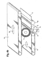
Fig. 2a, b is a diagrammatic view of a blade having a discontinuous glue application edge. -
Fig. 3a shows a roll with portions of a glue pattern oriented in MD. -
Fig. 3b shows portions of a glue pattern being oriented in CD. -
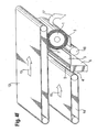
Figs. 4a to 4f show another embodiment of a tail sealing device illustrating stepwise the tail sealing process. -
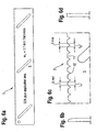
Figs. 5 to 12 show different embodiments of the blade. -
Fig. 1 illustrates in a diagrammatic manner a roll or log 1 conveyed in direction of thearrow 2 on a conveyingsurface 3. Beneath a glue application slot 4 (not illustrated inFig.4 ) ablade 5 and glue chamber 6 (not illustrated here) are provided for application glue on the tail sheet 7 on the roll 1. Theblade 5 is movable forward and backwards according to anarrow 8. - When a log from which shorter lengths of rolls are cut is leaving the rewinder head it rolls down a slope where a blade is placed in CD. The glue application surface of the blade carriers aforementioned glue and transfers it to the end of the roll (tail sheet) whilst continuing the revolution of the log down the slope, the glue carrying paper is wrapped further around the log and a tail sheet is attached to the log. Alternatively, spray application, moving spray head in CD or any continuous means like a wire in CD can provide the same result.
- The longitudinal axis of the roll 1 is marked in
Fig. 1 as having the reference letter a. - The glue application blade illustrated diagrammatically in
Fig. 2a has aglue application edge 10 having a glue application surface formed in its entirety bysurface portions 11a being crenels interrupted bymerlons 12. Theportions 11a are lengthwise oriented in CD and have a length Ii and themerlons 12 have a length I2. The blade itself has a width W1. -
Fig. 2b shows an embodiment of theblade 5 according to the invention. There are glue application portions lib. These are oriented in MD. These portions have a length I3 and are in CD in a distance of d and a width W2. - According to the blade illustrated in
Fig. 2a theportions 11a of the glue application surface is oriented in CD and the portions lib according toFig. 2b are oriented in MD, which leads to a glue application pattern result illustrated inFig. 3a and Fig. 3b . - In
Figs. 4a to 4f another mode of glue application and tail sealing is illustrated step by step fromFig. 4a to Fig. 4f . This device shows anupper conveyer belt 13 as an endless belt and alower conveyer belt 14 as an endless belt. Between these conveyer belts a roll 1 is conveyed in the direction of thearrow 15, since the conveyer belts are driven in the same direction. The tail or tail sheet 7 is sucked into the gap 4 and theblade 5 is retracted within theglue chamber 6. Downstream of the gap 4 astationary support 3 is illustrated, wherein apressure roller 16 is provided. This condition is illustrated inFig. 4a . In the next step according toFig. 4b theblade 5 is extended in an upper position and glue is applied here not to the tail sheet but on the circumference of the roll 1 where the tail sheet ends. Thereafter, theblade 5 is retracted and the roll 1 is furthermore transferred to the right side on thesupport 3. This is illustrated inFig. 4c . InFig. 4d a position is illustrated where the roll 1 is provided between theupper conveyer belt 13 and thepressure roller 16, which is then rotated such that the roll 1 is rotated between theconveyer belt 13 and thepressure roller 16. This is illustrated inFig. 4d and4e . InFig. 4e is visible the tail sheet already fastened by gluing and by the pressure roller the bonding effect is increased. Then the rotation of the pressure roller is stopped and the roll 1 is delivered in the direction of thearrow 17. InFig. 4e the applied glue pattern is marked by the reference number G. - Tests were made with some of several tail seal blades 1 to 8 according to
Fig. 5a to Fig. 12b (8 different blades), wherebyblades blades -
Fig. 5a shows the whole blade andFig. 5b an enlarged part of the blade 1 with the contour of the glue application edge. The thickness w1 of the blade is 2.1 mm themerlon 11 has a length l1 of 10 mm and the crenel 12 a length l2 of 5 mm. The glue application area, which means the sum of all portions of the glue application surface, is 66% of the whole glue application edge when the glue application edge is not interrupted or discontinuous. -
Tail seal blade 2 is illustrated inFig. 6a, 6b, 6c and 6d . TheFigs. 6b and 6d show the glue application surface having a groove so that the glue application surface is reduced. This is a possibility being not considered in connection with the tests. The glue application area here is 50% and the thickness w1 is also 2,1 mm. The length l1 is the same as the length l2 being 5 mm. -
Tail seal blade 3 is illustrated inFig. 7a and Fig. 7b . Here the glue application area is 100% and thethickness w 1 2,1 mm. This blade is used for comparison only, because this complies with the prior art. - By the blades 1 and 2 a glue pattern according to
Fig. 3b is achieved. - Tail seal blade 4 as illustrated in
Figs. 8a and 8b usesinserts 11b as illustrated inFig. 2b . The ame is fortail seal blade 5 illustrated inFigs. 9a and 9b . The glue application area is 66%. The thickness w2 is 2 mm and thewidth l 3 10 mm. The distance between theinserts 11b(d) is 15 mm. -
Tail seal blade 5 according toFigs. 9a and 9b has a glue application area of 33%. The thickness w2 is 2 mm and the widths l3 is 10 mm. The distance d between theinserts 11b is 30 mm. - Again
tail seal blade 6 according toFigs. 10a and 10b shows ablade 5 according to the prior art without discontinuous glue application surface. Therefore, the glue application area is 100% and the thickness w1 is 2,1 mm. - Tail seal blade 7 shows another crenellated configuration of the glue application edge, where the
crenels 12 have the same lengths l2 of 20 mm. The lengths l1 of themerlons 11 is different being 10 mm and 40 mm. Correspondingly, the glue application area is 50% and the thickness of the blade is 2,1 mm. - Finally,
tail seal blade 8 shows a blade according to the prior art without discontinuous glue application edge. Therefore, the glue application area is 100% but the thickness w 1 now is 2,8 mm. Thisseal blade 8 is illustrated inFigs. 12a and 12b . - The blades were tested with different glues according to the following table 1.
Variant Blade Glue Solid Content Color 1 8 STC 0190 (Henkel) ? --- 2 4 TS 0190 (Henkel) 6 --- 3 5 TS 0190 (Henkel) 6 --- 4 7 TS 0190 (Henkel) 6 --- - The test results are listed in table 2 as an evaluation matrix.
Tables 1 and 2 illustrate the variants 1 to 4. Variant A) Tear off behaviour B) Tear off behaviour C) Penetration behaviour through top ply D) Optical appearance E) Adhesion to ply underneath F) Penetration behaviour to ply underneath G) Optical appearance MD CD TS TS AP AP 1 5 1 4 4 5 5 4 2 1,5 2 3 1 1,5 1,5 1 3 1 2,5 3 1 1 1 1 4 1,5 2 3 1,5 1 1 1 - As follows, the basis for evaluation and weighting is as follows:
-
- A) Tear off behaviour MD:
- 1 = soft / 5 = strong
- B) Tear off behaviour CD:
- 1 = strong / 5 = soft
- C) Penetration behaviour through top ply:
- 1 = low / 5 = high
- D) Optical appearance:
- 1 = good / 5 = bad
-
- E) Adhesion to ply underneath:
- 1 = soft / 5 = strong
- F) Penetration behaviour to ply underneath:
- 1 = low / 5 = high
- G) Optical appearance:
- 1 = good / 5 = bad
- Table 2 demonstrates that those
variants blades 4, 5 and 7) result in an improved product performance in terms of optical appearance, adhesion and penetration compared with variant 1 according to the prior art (using blade 8). In addition product-rolls obtained fromvariants Table 3 shows the weighting factor with respect to the consumers and the production. Consumer Production Tear off MD TS 25% 75% Tear off CD TS 75% 25% Penetration TS 25% 75% Optical App. TS 25% 75% Adhesion AP 75% 25% Penetration AP 75% 25% Optical App. Ap 75% 25%
Claims (3)
- Device for gluing a tail cant or tail sheet of a roll or log (1) of wound web material, inter alia, comprising a support (3) for the roll or log (1), a dispenser of glue (6), at least one movable blade (5) on which a gluing application edge (10) is provided, said blade (5) being oriented parallel to the roll or log longitudinal axis ( CD), wherein
the glue application edge (10) of the blade (5) has an interrupted glue application surface having a row of separated glue application surface portions,
characterized in that glue application surface portions (11b) are lengthwise oriented in a direction perpendicular to the roll or log longitudinal axis (MD), wherein the glue application surface of the blade (5) is formed by parts (11b) being oriented lengthwise substantially perpendicularly to the longitudinal extension of the blade (5) and extend beyond the width (w 1) of the blade. - Device according to claim 1, characterized in that the parts (11b) are integral with the blade (5).
- Device according to claim 1, characterized in that the parts (11b) are fastened to the blade (5) in a distanced manner.
Applications Claiming Priority (1)
| Application Number | Priority Date | Filing Date | Title |
|---|---|---|---|
| PCT/EP2006/011365 WO2008064693A1 (en) | 2006-11-27 | 2006-11-27 | Device for gluing a tail cant of a roll and product roll |
Publications (2)
| Publication Number | Publication Date |
|---|---|
| EP2094594A1 EP2094594A1 (en) | 2009-09-02 |
| EP2094594B1 true EP2094594B1 (en) | 2014-04-30 |
Family
ID=38268723
Family Applications (1)
| Application Number | Title | Priority Date | Filing Date |
|---|---|---|---|
| EP06818855.6A Active EP2094594B1 (en) | 2006-11-27 | 2006-11-27 | Device for gluing a tail cant of a roll and product roll |
Country Status (8)
| Country | Link |
|---|---|
| US (1) | US20100028596A1 (en) |
| EP (1) | EP2094594B1 (en) |
| CN (1) | CN101541656B (en) |
| AU (1) | AU2006351174B2 (en) |
| BR (1) | BRPI0622156A2 (en) |
| ES (1) | ES2463480T3 (en) |
| MX (1) | MX2009003711A (en) |
| WO (1) | WO2008064693A1 (en) |
Families Citing this family (3)
| Publication number | Priority date | Publication date | Assignee | Title |
|---|---|---|---|---|
| US9771232B2 (en) * | 2013-03-13 | 2017-09-26 | Georgia-Pacific Consumer Products Lp | Systems and methods for parent roll tail reduction |
| CN108546522A (en) * | 2018-05-14 | 2018-09-18 | 江苏杰立胶粘材料科技有限公司 | Transferable high viscous double faced adhesive tapes of a kind of PET and preparation method thereof |
| JP2021087615A (en) * | 2019-12-04 | 2021-06-10 | 日本製紙クレシア株式会社 | Paper roll body |
Family Cites Families (10)
| Publication number | Priority date | Publication date | Assignee | Title |
|---|---|---|---|---|
| US2329527A (en) * | 1941-01-18 | 1943-09-14 | Atlantic Gummed Paper Corp | Method of manufacturing rolls of tape |
| US3289898A (en) * | 1966-03-08 | 1966-12-06 | Scott Paper Co | Metering and dispensing device for viscous liquids |
| US3470052A (en) * | 1966-03-28 | 1969-09-30 | Scott Paper Co | Method and apparatus for winding a multiple ply web |
| DE2621710A1 (en) * | 1976-05-15 | 1977-12-01 | Sanitaria Gmbh | Machine for applying adhesive to large sheets - has array of rods moving in and out of adhesive container |
| JPH04341446A (en) * | 1991-05-17 | 1992-11-27 | C I Kasei Co Ltd | Roll end fixing method for resin film |
| IT1252896B (en) * | 1991-11-08 | 1995-07-05 | Perini Fabio Spa | IMPROVED EQUIPMENT FOR GLUING THE FINAL EDGE OF ROLLS OF TAPE MATERIAL |
| IT1267563B1 (en) | 1993-12-10 | 1997-02-05 | Perini Fabio Spa | GLUE DISPENSER AND DEVICE USING THE REGULATOR |
| IT1307820B1 (en) * | 1999-12-02 | 2001-11-19 | Perini Fabio Spa | MACHINE AND METHOD FOR THE PRODUCTION OF ROLLS OF IMPREGNATED TAPE MATERIAL. |
| ITFI20020119A1 (en) * | 2002-07-08 | 2004-01-08 | Fabio Perini | REWINDING MACHINE AND METHOD FOR MANUFACTURING VARIOUS SIZE PAPER STICKS |
| JP4326458B2 (en) * | 2004-11-09 | 2009-09-09 | 日本製紙クレシア株式会社 | Sanitary paper roll products |
-
2006
- 2006-11-27 AU AU2006351174A patent/AU2006351174B2/en not_active Ceased
- 2006-11-27 ES ES06818855.6T patent/ES2463480T3/en active Active
- 2006-11-27 WO PCT/EP2006/011365 patent/WO2008064693A1/en not_active Ceased
- 2006-11-27 MX MX2009003711A patent/MX2009003711A/en active IP Right Grant
- 2006-11-27 BR BRPI0622156-4A patent/BRPI0622156A2/en not_active IP Right Cessation
- 2006-11-27 US US12/442,866 patent/US20100028596A1/en not_active Abandoned
- 2006-11-27 CN CN2006800564690A patent/CN101541656B/en active Active
- 2006-11-27 EP EP06818855.6A patent/EP2094594B1/en active Active
Also Published As
| Publication number | Publication date |
|---|---|
| WO2008064693A1 (en) | 2008-06-05 |
| ES2463480T3 (en) | 2014-05-28 |
| EP2094594A1 (en) | 2009-09-02 |
| US20100028596A1 (en) | 2010-02-04 |
| CN101541656B (en) | 2012-08-08 |
| AU2006351174A1 (en) | 2008-06-05 |
| AU2006351174B2 (en) | 2012-09-06 |
| CN101541656A (en) | 2009-09-23 |
| BRPI0622156A2 (en) | 2011-12-27 |
| MX2009003711A (en) | 2009-06-26 |
Similar Documents
| Publication | Publication Date | Title |
|---|---|---|
| US7523884B2 (en) | Rewinding machine with gluing device to glue the final edge of the log formed and relative winding method | |
| CN1253364C (en) | Rewinding machine for forming a wound roll of web material and method of producing the same | |
| EP2253568B1 (en) | Winding device and method for tearing off web material by planetary-roller | |
| JP5622478B2 (en) | Manufacturing method of tissue paper products | |
| US7846286B2 (en) | Device and method for closing the tail end of logs of web material and relative logs obtained therewith | |
| US7398942B2 (en) | Rewinding machine to produce logs of web material and relative winding method | |
| AU2006351174B2 (en) | Device for gluing a tail cant of a roll and product roll | |
| JP5591313B2 (en) | Packaging machine | |
| AU2009244023B2 (en) | Printing carrier consisting of at least two flat partial printing carriers assembled in a coplanar manner, partial printing carriers, and method for the production thereof | |
| US12208980B2 (en) | Rewinding machine and method for the production of logs of paper material | |
| US12162707B2 (en) | Rewinding machine and method for the production of logs of paper material | |
| RU2420446C2 (en) | Device to glue roll end edge to article roll | |
| JPH10211664A (en) | Corrugated sheet processing equipment | |
| US20060000544A1 (en) | Method of producing cartons | |
| JP4310559B2 (en) | Method and apparatus for attaching a plurality of small slips to an envelope surface | |
| KR200448294Y1 (en) | Medicine bag manufacturing equipment | |
| JPH1058566A (en) | Method and apparatus for laminating thick letters and thin paper | |
| JPH0631834A (en) | Bag-making method |
Legal Events
| Date | Code | Title | Description |
|---|---|---|---|
| PUAI | Public reference made under article 153(3) epc to a published international application that has entered the european phase |
Free format text: ORIGINAL CODE: 0009012 |
|
| 17P | Request for examination filed |
Effective date: 20090326 |
|
| AK | Designated contracting states |
Kind code of ref document: A1 Designated state(s): AT BE BG CH CY CZ DE DK EE ES FI FR GB GR HU IE IS IT LI LT LU LV MC NL PL PT RO SE SI SK TR |
|
| DAX | Request for extension of the european patent (deleted) | ||
| 17Q | First examination report despatched |
Effective date: 20100223 |
|
| GRAP | Despatch of communication of intention to grant a patent |
Free format text: ORIGINAL CODE: EPIDOSNIGR1 |
|
| INTG | Intention to grant announced |
Effective date: 20131210 |
|
| GRAS | Grant fee paid |
Free format text: ORIGINAL CODE: EPIDOSNIGR3 |
|
| GRAA | (expected) grant |
Free format text: ORIGINAL CODE: 0009210 |
|
| AK | Designated contracting states |
Kind code of ref document: B1 Designated state(s): AT BE BG CH CY CZ DE DK EE ES FI FR GB GR HU IE IS IT LI LT LU LV MC NL PL PT RO SE SI SK TR |
|
| REG | Reference to a national code |
Ref country code: GB Ref legal event code: FG4D Ref country code: CH Ref legal event code: EP |
|
| REG | Reference to a national code |
Ref country code: AT Ref legal event code: REF Ref document number: 664971 Country of ref document: AT Kind code of ref document: T Effective date: 20140515 |
|
| REG | Reference to a national code |
Ref country code: IE Ref legal event code: FG4D |
|
| REG | Reference to a national code |
Ref country code: ES Ref legal event code: FG2A Ref document number: 2463480 Country of ref document: ES Kind code of ref document: T3 Effective date: 20140528 |
|
| REG | Reference to a national code |
Ref country code: DE Ref legal event code: R096 Ref document number: 602006041355 Country of ref document: DE Effective date: 20140612 |
|
| REG | Reference to a national code |
Ref country code: AT Ref legal event code: MK05 Ref document number: 664971 Country of ref document: AT Kind code of ref document: T Effective date: 20140430 |
|
| REG | Reference to a national code |
Ref country code: LT Ref legal event code: MG4D |
|
| REG | Reference to a national code |
Ref country code: NL Ref legal event code: VDEP Effective date: 20140430 |
|
| PG25 | Lapsed in a contracting state [announced via postgrant information from national office to epo] |
Ref country code: LT Free format text: LAPSE BECAUSE OF FAILURE TO SUBMIT A TRANSLATION OF THE DESCRIPTION OR TO PAY THE FEE WITHIN THE PRESCRIBED TIME-LIMIT Effective date: 20140430 Ref country code: GR Free format text: LAPSE BECAUSE OF FAILURE TO SUBMIT A TRANSLATION OF THE DESCRIPTION OR TO PAY THE FEE WITHIN THE PRESCRIBED TIME-LIMIT Effective date: 20140731 Ref country code: NL Free format text: LAPSE BECAUSE OF FAILURE TO SUBMIT A TRANSLATION OF THE DESCRIPTION OR TO PAY THE FEE WITHIN THE PRESCRIBED TIME-LIMIT Effective date: 20140430 Ref country code: BG Free format text: LAPSE BECAUSE OF FAILURE TO SUBMIT A TRANSLATION OF THE DESCRIPTION OR TO PAY THE FEE WITHIN THE PRESCRIBED TIME-LIMIT Effective date: 20140730 Ref country code: IS Free format text: LAPSE BECAUSE OF FAILURE TO SUBMIT A TRANSLATION OF THE DESCRIPTION OR TO PAY THE FEE WITHIN THE PRESCRIBED TIME-LIMIT Effective date: 20140830 Ref country code: FI Free format text: LAPSE BECAUSE OF FAILURE TO SUBMIT A TRANSLATION OF THE DESCRIPTION OR TO PAY THE FEE WITHIN THE PRESCRIBED TIME-LIMIT Effective date: 20140430 Ref country code: CY Free format text: LAPSE BECAUSE OF FAILURE TO SUBMIT A TRANSLATION OF THE DESCRIPTION OR TO PAY THE FEE WITHIN THE PRESCRIBED TIME-LIMIT Effective date: 20140430 |
|
| PG25 | Lapsed in a contracting state [announced via postgrant information from national office to epo] |
Ref country code: PL Free format text: LAPSE BECAUSE OF FAILURE TO SUBMIT A TRANSLATION OF THE DESCRIPTION OR TO PAY THE FEE WITHIN THE PRESCRIBED TIME-LIMIT Effective date: 20140430 Ref country code: LV Free format text: LAPSE BECAUSE OF FAILURE TO SUBMIT A TRANSLATION OF THE DESCRIPTION OR TO PAY THE FEE WITHIN THE PRESCRIBED TIME-LIMIT Effective date: 20140430 Ref country code: SE Free format text: LAPSE BECAUSE OF FAILURE TO SUBMIT A TRANSLATION OF THE DESCRIPTION OR TO PAY THE FEE WITHIN THE PRESCRIBED TIME-LIMIT Effective date: 20140430 Ref country code: AT Free format text: LAPSE BECAUSE OF FAILURE TO SUBMIT A TRANSLATION OF THE DESCRIPTION OR TO PAY THE FEE WITHIN THE PRESCRIBED TIME-LIMIT Effective date: 20140430 |
|
| PG25 | Lapsed in a contracting state [announced via postgrant information from national office to epo] |
Ref country code: PT Free format text: LAPSE BECAUSE OF FAILURE TO SUBMIT A TRANSLATION OF THE DESCRIPTION OR TO PAY THE FEE WITHIN THE PRESCRIBED TIME-LIMIT Effective date: 20140901 |
|
| PG25 | Lapsed in a contracting state [announced via postgrant information from national office to epo] |
Ref country code: BE Free format text: LAPSE BECAUSE OF FAILURE TO SUBMIT A TRANSLATION OF THE DESCRIPTION OR TO PAY THE FEE WITHIN THE PRESCRIBED TIME-LIMIT Effective date: 20140430 Ref country code: RO Free format text: LAPSE BECAUSE OF FAILURE TO SUBMIT A TRANSLATION OF THE DESCRIPTION OR TO PAY THE FEE WITHIN THE PRESCRIBED TIME-LIMIT Effective date: 20140430 Ref country code: SK Free format text: LAPSE BECAUSE OF FAILURE TO SUBMIT A TRANSLATION OF THE DESCRIPTION OR TO PAY THE FEE WITHIN THE PRESCRIBED TIME-LIMIT Effective date: 20140430 Ref country code: CZ Free format text: LAPSE BECAUSE OF FAILURE TO SUBMIT A TRANSLATION OF THE DESCRIPTION OR TO PAY THE FEE WITHIN THE PRESCRIBED TIME-LIMIT Effective date: 20140430 Ref country code: DK Free format text: LAPSE BECAUSE OF FAILURE TO SUBMIT A TRANSLATION OF THE DESCRIPTION OR TO PAY THE FEE WITHIN THE PRESCRIBED TIME-LIMIT Effective date: 20140430 Ref country code: EE Free format text: LAPSE BECAUSE OF FAILURE TO SUBMIT A TRANSLATION OF THE DESCRIPTION OR TO PAY THE FEE WITHIN THE PRESCRIBED TIME-LIMIT Effective date: 20140430 |
|
| REG | Reference to a national code |
Ref country code: DE Ref legal event code: R097 Ref document number: 602006041355 Country of ref document: DE |
|
| PLBE | No opposition filed within time limit |
Free format text: ORIGINAL CODE: 0009261 |
|
| STAA | Information on the status of an ep patent application or granted ep patent |
Free format text: STATUS: NO OPPOSITION FILED WITHIN TIME LIMIT |
|
| 26N | No opposition filed |
Effective date: 20150202 |
|
| REG | Reference to a national code |
Ref country code: DE Ref legal event code: R097 Ref document number: 602006041355 Country of ref document: DE Effective date: 20150202 |
|
| PG25 | Lapsed in a contracting state [announced via postgrant information from national office to epo] |
Ref country code: MC Free format text: LAPSE BECAUSE OF FAILURE TO SUBMIT A TRANSLATION OF THE DESCRIPTION OR TO PAY THE FEE WITHIN THE PRESCRIBED TIME-LIMIT Effective date: 20140430 Ref country code: LU Free format text: LAPSE BECAUSE OF FAILURE TO SUBMIT A TRANSLATION OF THE DESCRIPTION OR TO PAY THE FEE WITHIN THE PRESCRIBED TIME-LIMIT Effective date: 20141127 |
|
| REG | Reference to a national code |
Ref country code: CH Ref legal event code: PL |
|
| PG25 | Lapsed in a contracting state [announced via postgrant information from national office to epo] |
Ref country code: SI Free format text: LAPSE BECAUSE OF FAILURE TO SUBMIT A TRANSLATION OF THE DESCRIPTION OR TO PAY THE FEE WITHIN THE PRESCRIBED TIME-LIMIT Effective date: 20140430 Ref country code: LI Free format text: LAPSE BECAUSE OF NON-PAYMENT OF DUE FEES Effective date: 20141130 Ref country code: CH Free format text: LAPSE BECAUSE OF NON-PAYMENT OF DUE FEES Effective date: 20141130 |
|
| REG | Reference to a national code |
Ref country code: IE Ref legal event code: MM4A |
|
| PG25 | Lapsed in a contracting state [announced via postgrant information from national office to epo] |
Ref country code: IE Free format text: LAPSE BECAUSE OF NON-PAYMENT OF DUE FEES Effective date: 20141127 |
|
| REG | Reference to a national code |
Ref country code: FR Ref legal event code: PLFP Year of fee payment: 10 |
|
| PG25 | Lapsed in a contracting state [announced via postgrant information from national office to epo] |
Ref country code: HU Free format text: LAPSE BECAUSE OF FAILURE TO SUBMIT A TRANSLATION OF THE DESCRIPTION OR TO PAY THE FEE WITHIN THE PRESCRIBED TIME-LIMIT; INVALID AB INITIO Effective date: 20061127 Ref country code: TR Free format text: LAPSE BECAUSE OF FAILURE TO SUBMIT A TRANSLATION OF THE DESCRIPTION OR TO PAY THE FEE WITHIN THE PRESCRIBED TIME-LIMIT Effective date: 20140430 |
|
| REG | Reference to a national code |
Ref country code: FR Ref legal event code: PLFP Year of fee payment: 11 |
|
| REG | Reference to a national code |
Ref country code: FR Ref legal event code: PLFP Year of fee payment: 12 |
|
| REG | Reference to a national code |
Ref country code: ES Ref legal event code: PC2A Owner name: ESSITY OPERATIONS MANNHEIM GMBH Effective date: 20181121 Ref country code: DE Ref legal event code: R082 Ref document number: 602006041355 Country of ref document: DE Representative=s name: HOFFMANN - EITLE PATENT- UND RECHTSANWAELTE PA, DE Ref country code: DE Ref legal event code: R081 Ref document number: 602006041355 Country of ref document: DE Owner name: ESSITY OPERATIONS MANNHEIM GMBH, DE Free format text: FORMER OWNER: SCA HYGIENE PRODUCTS GMBH, 68305 MANNHEIM, DE |
|
| PGFP | Annual fee paid to national office [announced via postgrant information from national office to epo] |
Ref country code: DE Payment date: 20251126 Year of fee payment: 20 |
|
| PGFP | Annual fee paid to national office [announced via postgrant information from national office to epo] |
Ref country code: GB Payment date: 20251125 Year of fee payment: 20 |
|
| PGFP | Annual fee paid to national office [announced via postgrant information from national office to epo] |
Ref country code: IT Payment date: 20251121 Year of fee payment: 20 |
|
| PGFP | Annual fee paid to national office [announced via postgrant information from national office to epo] |
Ref country code: FR Payment date: 20251125 Year of fee payment: 20 |
|
| PGFP | Annual fee paid to national office [announced via postgrant information from national office to epo] |
Ref country code: ES Payment date: 20251209 Year of fee payment: 20 |