EP2094536B1 - Truck and bodybuilder module for this truck, method, memory and software to configure the bodybuilder module - Google Patents
Truck and bodybuilder module for this truck, method, memory and software to configure the bodybuilder module Download PDFInfo
- Publication number
- EP2094536B1 EP2094536B1 EP06847288A EP06847288A EP2094536B1 EP 2094536 B1 EP2094536 B1 EP 2094536B1 EP 06847288 A EP06847288 A EP 06847288A EP 06847288 A EP06847288 A EP 06847288A EP 2094536 B1 EP2094536 B1 EP 2094536B1
- Authority
- EP
- European Patent Office
- Prior art keywords
- truck
- volatile memory
- auxiliary unit
- memory zone
- module
- Prior art date
- Legal status (The legal status is an assumption and is not a legal conclusion. Google has not performed a legal analysis and makes no representation as to the accuracy of the status listed.)
- Not-in-force
Links
- 230000015654 memory Effects 0.000 title claims abstract description 58
- 238000000034 method Methods 0.000 title claims abstract description 12
- 238000010276 construction Methods 0.000 claims description 5
- 230000007935 neutral effect Effects 0.000 description 4
- 230000005540 biological transmission Effects 0.000 description 2
- 230000001934 delay Effects 0.000 description 2
- 238000010586 diagram Methods 0.000 description 2
- 230000006870 function Effects 0.000 description 2
- 230000004048 modification Effects 0.000 description 2
- 238000012986 modification Methods 0.000 description 2
- 238000009434 installation Methods 0.000 description 1
- 238000004519 manufacturing process Methods 0.000 description 1
- 230000001960 triggered effect Effects 0.000 description 1
Images


Classifications
-
- B—PERFORMING OPERATIONS; TRANSPORTING
- B60—VEHICLES IN GENERAL
- B60R—VEHICLES, VEHICLE FITTINGS, OR VEHICLE PARTS, NOT OTHERWISE PROVIDED FOR
- B60R25/00—Fittings or systems for preventing or indicating unauthorised use or theft of vehicles
Definitions
- the above bodybuilder electronic module has the ability to satisfy the need of very different bodybuilders because the information retrieved from the auxiliary unit connection can be a combination of a plurality of data transmitted on the truck bus.
- the above bodybuilder electronic module is very flexible.
- the invention also relates to a bodybuilder electronic module suitable to be implemented within the above truck.
- Figure 2 shows in more details bodybuilder electronic module 20.
- the engine speed, vehicle speed and engine torque are numerical values.
- the neutral state, clutch state and park brake state are Boolean values.
- the numerical values are sent to respective comparators 40-42.
- Each comparator 40-42 compares the numerical values to a respective threshold S i which can be, configured.
- the output of comparator 40-42 is a Boolean value equal to "1" if the numerical value is superior to threshold S i and, otherwise, equal to "0".
- Electronic module 20 has a connection to transmit data and receive data from auxiliary unit 24.
- this connection is a plug 44 designed to fit into plug 22 to electrically connect auxiliary unit 24 to electronic module 20.
- plug 44 has four pins 46 to 49.
- Pins 46 and 47 are output pins that output information from truck 2 to auxiliary unit 24.
- Pins 48 and 49 are input pins that receive information from auxiliary unit 24.
- Pins 48 and 49 are directly connected through respective delay lines 50 and 52 to respective inputs of calculators 54 and 56.
- Outputs of comparator 40 to 42 as well as the Boolean value received through interface 38 are also connected to respective inputs of calculators 54 and 56.
- the mathematical operation executed by calculators 54 and 56 is defined in a list 64 stored in a non-volatile memory 66.
- List 64 specifies for each mathematical operation to be executed which data in list 58 are to be used as operand and which operator in list 60 has to be used.
- list 64 contains references or pointers to the operators and operands of lists 58 and 60.
- calculators 54 and 56 are only able in this embodiment to execute Boolean operations.
- Figure 3 shows a window 98 displayed on screen 82 when software 92 is executed by microprocessor 90.
- This screen includes a first area 100 to define the mathematical operation to be executed by electronic module 20.
- Area 100 includes three list zones 102-104. Each list zone is populated with the name of the data which can be used as operand by electronic module 20. Each name corresponds to a data stored in list 58. Each zone 102-104 allows to select at most one of these names.
- zone 107 is identical to zone 106. Zone 107 selects the operator that will operate on the data selected in zones 103 and 104.
- Area 100 also includes three buttons 108A, 108B and 108C placed under list zones 102-104, respectively. When one of these buttons 108A, 108B and 108C is selected, the operation NOT is applied to the data selected in the list zone just above.
- window 98 has a third area 120 that includes two fields 122 and 124 designed to receive numerical values that correspond to the time delays that delay lines 50 and 52 will implement, respectively.
- truck 2 and software 92 will now be described with reference to figure 4 .
- an operator defines the mathematical operations to be executed by electronic module 20.
- step 134 the operator selects in each zones 102, 103 and 104 the operands to be used in the mathematical operation. Subsequently, in step 136, the operator selects in zones 106 and 107 the operators to apply to the operands.
- step 148 auxiliary unit 24 is connected to electronic module 20 through the use of plugs 22 and 44. Thereafter, electronic module 20 is activated to provide the required information to auxiliary unit 24.
- first and second memories 62 and 66 may correspond to separate zones of the same memory.
- auxiliary unit plug 44 and configuration plug 70 may be housed within the same connector
Landscapes
- Engineering & Computer Science (AREA)
- Mechanical Engineering (AREA)
- Control By Computers (AREA)
- Stored Programmes (AREA)
- Time Recorders, Dirve Recorders, Access Control (AREA)
- Traffic Control Systems (AREA)
- Near-Field Transmission Systems (AREA)
- General Factory Administration (AREA)
Abstract
Description
- The present invention relates to a truck and a bodybuilder electronic module for this truck, a method, a memory and a software to configure the bodybuilder electronic module.
- Typically, a truck includes:
- a plurality of electronic control units able to control actuators of the truck and/or sensors, the control unit and the sensors being able to generate respective data that represent the operative state of the truck,
- a bus linking together the electronic control units and the sensors,
- a bodybuilder electronic module connected to the bus, the electronic module comprising an auxiliary unit connection to connect an auxiliary unit chosen amongst a plurality of different auxiliary units which can be installed on this truck, each auxiliary unit being able to drive an auxiliary equipment added to the truck after its construction, this connection being able to transmit, to the auxiliary unit, information on the operating state of the truck which is built from data read on the bus, and
- a configuration connection to connect and, alternatively, to disconnect a configuration computer to the bodybuilder electronic module,
- Bodybuilders are companies that install auxiliary units on the trucks. The auxiliary units drive auxiliary equipments like a movable container, a pump, a tank, a rubbish compactor and so on.
- For example, the auxiliary units comprise a motor that drive a shaft, a valve, a cylinder or other actuators of the auxiliary equipment.
- The auxiliary units need to be triggered or stopped depending on the state of operation of the truck. For example, the auxiliary units have to lift a container only if the park brake is on.
- Thus, auxiliary units need to retrieve data from the bus of the truck.
-
EP 1 196 310 discloses a bodybuilder electronic module which is called a remote interface module. This module includes a plug to connect the auxiliary unit. It is also possible to configure which output pin of the plug will be used and which vehicle data will be outputted through it. To this end, specific functions and tables are implemented within an ECS (Electrical System Controller) of the truck. The ECS is connected to the remote interface module through the bus. - Harmful modifications can be done because the specific functions and tables are directly implemented within the ECS. Accordingly, configuration of the remote interface module can only be done during the truck manufacturing process by specialized persons.
- Accordingly, it is an object of the invention to provide a truck with a bodybuilder electronic module that can be used by bodybuilders while preserving a high level of flexibility.
- The invention provides a truck having a bodybuilder electronic module comprising:
- a first non-volatile memory zone, content of which cannot be modified through the configuration connection, the first non-volatile memory zone storing a first predetermined list of authorized mathematical operators and a second predetermined list of a plurality of authorized operands, each operand corresponding to a data generated by one of the electronic control units or one of the sensors,
- a second non-volatile memory zone, content of which can be modified through the configuration connection, the second non-volatile memory zone storing information defining a mathematical operation, the mathematical operation being formed by a combination of operators and operands,
- a microprocessor able:
- to execute the mathematical operation defined by the information stored in the second non-volatile memory zone only if each of the operators and operands of the defined mathematical operation matches an authorized operator or operand stored in the first non-volatile memory zone, and
- to transmit the result of the executed mathematical operation to the auxiliary unit through the auxiliary unit connection.
- The above bodybuilder electronic module has the ability to satisfy the need of very different bodybuilders because the information retrieved from the auxiliary unit connection can be a combination of a plurality of data transmitted on the truck bus. Thus, the above bodybuilder electronic module is very flexible.
- When using the above bodybuilder electronic module it is only possible to implement an operation which is harmless for the truck. This is due to the fact that only a predetermined set of mathematical operators and operands can be executed. Thus, the bodybuilder electronic module configuration can be done by the bodybuilder without any risk of causing any damage to the truck.
- The embodiments of the above truck may comprise the following features:
- the bus is a CAN (Control Area Network) bus.
- The invention also relates to a bodybuilder electronic module suitable to be implemented within the above truck.
- The embodiments of the above bodybuilder electronic module may comprise one or several of the following features:
- an interface to directly connect the electronic module to the truck bus, this interface being only able to read data on the bus without being able to transmit data on this bus,
- the first list is only composed of Boolean operators and threshold comparators,
- the module also comprises a configuration connection to connect and, alternatively, to disconnect the configuration computer to the bodybuilder electronic module,
- the module also comprises a plug to connect and, alternatively, to disconnect the module to/from the truck bus,
- the auxiliary unit connection is also able to receive data from the auxiliary unit, and the second predetermined list of operands also includes an operand corresponding to the data received through the input pin,
- the second non-volatile memory zone stores information defining a threshold, and the microprocessor is able to compare data read on the bus to the defined threshold, and
- at least one configurable delay line able to delay the data read on the bus or on the input pin by a configurable time delay, and the second non-volatile memory zone includes information defining the time delay used in the configuration line.
- The above embodiments of the bodybuilder electronic module present the following advantages:
- using an interface which is only able to read data on the bus increases the security because the electronic module cannot be used to alter the truck data. Furthermore, the electronic module can be implemented in a truck without requiring any configuration or modification of the truck;
- using only Boolean operators or comparators make the electronic module easier to program;
- including the configuration plug within the electronic module makes this electronic module safer because it does not need to use any other equipment embedded within the truck like for example the bus;
- providing the electronic module with a connector to connect it to the bus makes the installation of this electronic module easier;
- providing the electronic module with an auxiliary unit connection able to receive data from the auxiliary unit increases the flexibility of the electronic module; and
- providing the electronic module with delay lines and threshold further increases the flexibility of this electronic module.
- The invention also relates to a method to configure the above bodybuilder electronic module, the method comprising:
- providing the above bodybuilder electronic module,
- displaying mathematical operators and operands in respective list zones, each list zone being populated only with the authorized mathematical operators and operands, respectively,
- acquiring the operator and operand selected by an operator in the list zone to define a mathematical operation, and
- downloading the defined mathematical operation into the second non-volatile memory zone from a computer connected to the electronic module through the configuration plug.
- The invention also relates to a memory and a software including instructions to execute the above method to configure the bodybuilder electronic module when those instructions are executed by a computer.
- These and other aspects of the invention will be apparent from the following description, drawings and claims.
-
-
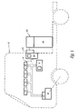
Figure 1 is a schematic diagram of a vehicle equipped with a bodybuilder electronic module; -
Figure 2 is a more detailed view of the bodybuilder electronic module used in the vehicle offigure 1 ; -
Figure 3 is a schematic diagram of a display of a software used to configure the bodybuilder electronic module offigure 2 ; and -
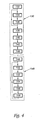
Figure 4 is a flowchart of a method to configure the bodybuilder electronic module offigure 2 . - In the drawings, the same reference numbers are used to designate the same elements.
- In the following description, well-known functional constructions by a person of ordinary skill in the art are not described in details.
-
Figure 1 shows an automotive vehicle. More precisely,figure 1 shows atruck 2. -
Truck 2 includes many ECU (Electronic Control Units) and sensors which are connected to each other through aserial data bus 4. For example,bus 4 is a multicast bus like a CAN (Controller Area Network) bus. ECUs are embedded systems that control one or more of the electrical subsystems of the truck. Some trucks may have up to thirty ECUs. For example,truck 2 includes the following ECU: - engine control unit,
- transmission control unit (TCU),
- man machine interface (MMI),
- door control unit,
- seat control unit,
- climate control unit,
- anti-lock braking system (ABS) unit or Electronic Braking System (EBS) unit.
- For simplicity, only
engine control unit 6 andEBS unit 8 have been illustrated infigure 1 . -
Unit 6 controls anengine 10 that drives truck wheels. -
Unit 6 is able to generate and transmit data onbus 4. For example,engine 6 transmits data like engine speed and engine torque. - For simplicity, only the following sensors are represented in
figure 1 as being connected to bus 4: - a
sensor 12 that outputs the park brake state onbus 4, - a
sensor 13 that outputs the vehicle speed onbus 4, - a
sensor 14 that transmits the clutch state onbus 4, - a
sensor 16 that transmits Boolean data indicating that the transmission is in the neutral state or not. - A bodybuilder
electronic module 20 is also directly connected tobus 4.Electronic module 20 is also connected by aplug 22 to anauxiliary unit 24.Auxiliary unit 24 is permanently mounted ontruck 2. For example,auxiliary unit 24 is an electrical motor, a thermal motor or a pump that is used to driveauxiliary equipment 26. -
Auxiliary equipment 26 is permanently mounted invehicle 2. For example,equipment 26 is a tank, a movable container, a valve, a hydraulic/automatic cylinder, a compactor. -
Figure 2 shows in more details bodybuilderelectronic module 20. -
Electronic module 20 has aplug 30 to connectelectronic module 20 tobus 4 and, alternately, to disconnectelectronic module 20 frombus 4. Thus,module 20 takes the form of a removable box that includes every electronic components necessary to interfaceauxiliary unit 24 tobus 4. - As shown in
figure 2 ,bus 4 includes twowires wires -
Bus 4 has acorresponding plug 36 intended to fit intoplug 30. -
Plug 30 is directly connected through two wires to aninterface 38 which is only able to read data onbus 4. For example,interface 38 is able to read the following data: - engine speed,
- vehicle speed,
- engine torque,
- neutral state,
- clutch state,
- park brake state.
- The engine speed, vehicle speed and engine torque are numerical values. The neutral state, clutch state and park brake state are Boolean values.
- In this embodiment, the numerical values are sent to respective comparators 40-42. Each comparator 40-42 compares the numerical values to a respective threshold Si which can be, configured. The output of comparator 40-42 is a Boolean value equal to "1" if the numerical value is superior to threshold Si and, otherwise, equal to "0".
-
Electronic module 20 has a connection to transmit data and receive data fromauxiliary unit 24. Here, this connection is aplug 44 designed to fit intoplug 22 to electrically connectauxiliary unit 24 toelectronic module 20. In this example, plug 44 has fourpins 46 to 49.Pins truck 2 toauxiliary unit 24.Pins auxiliary unit 24.Pins respective delay lines calculators comparator 40 to 42 as well as the Boolean value received throughinterface 38 are also connected to respective inputs ofcalculators - Each
calculator bus 4 and data received through input pins 48 and 49. The data that can be used as operand in the mathematical operation are defined in alist 58. The mathematical operators that can be used in this mathematical operation are defined in alist 60.Lists non-volatile memory 62. For example,list 58 includes the following data: - engine speed,
- vehicle speed,
- engine torque,
- neutral state,
- clutch state,
- park brake state,
- input pins 48 and 49, and
- a logical "0".
-
List 60 only includes Boolean operators. For example,list 60 includes the following Boolean operators: AND, XOR, OR and NOT. - The mathematical operation executed by
calculators list 64 stored in anon-volatile memory 66.List 64 specifies for each mathematical operation to be executed which data inlist 58 are to be used as operand and which operator inlist 60 has to be used. For example,list 64 contains references or pointers to the operators and operands oflists - Accordingly,
calculators - Each
calculator pins Electronic module 20 also includes a configuration connection to received configuration data from an internal computer. Here, this connection is aplug 70 through which is receivedlist 64.Plug 70 can only be used to store new data inmemory 66 but not inmemory 62. Thus, lists 58 and 60 are not modifiable throughplug 70. -
Plug 70 is designed to fit into anexternal plug 72 which is fixed at the extremity of awire 74 connecting anadapter 76 toelectronic module 20.Adapter 76 is for example able to convert data received through a standard bus, like USB or RS232 bus into data transmitted onwire 74. This standard bus is connected to anexternal computer 80.Computer 80 has ascreen 82, akeyboard 84, acentral unit 86 and amemory 88. -
Central unit 86 includes at least onemicroprocessor 90 able to execute instructions recorded inmemory 88. Asoftware 92 is stored inmemory 88. Thesoftware 92 includes instructions to define a mathematical operation suitable to be executed byelectronic module 20 and to download the defined mathematical operation aslist 64 inmemory 66 throughadapter 76,connection 74 and plugs 72 and 70, when executed. -
Interface 38, comparators 40-42,delay lines calculators microprocessor 94. To this end,microprocessor 94 executes instructions recorded inmemory 62, for example. -
Figure 3 shows awindow 98 displayed onscreen 82 whensoftware 92 is executed bymicroprocessor 90. This screen includes afirst area 100 to define the mathematical operation to be executed byelectronic module 20.Area 100 includes three list zones 102-104. Each list zone is populated with the name of the data which can be used as operand byelectronic module 20. Each name corresponds to a data stored inlist 58. Each zone 102-104 allows to select at most one of these names. -
Area 100 also includes twolist zones Zone 106 includes three names, each one corresponding to one of the operator names stored inlist 60. The user can select at most one of the names inzone 106.Zone 106 defines the operators that operate on the data selected inzone - For example,
zone 107 is identical tozone 106.Zone 107 selects the operator that will operate on the data selected inzones -
Area 100 also includes threebuttons buttons -
Window 98 also includes asecond area 110 used to configure the threshold Si of comparators 40-42, respectively. For example,area 110 is divided into three lines, each line corresponding to one of the comparators 40-42. Afirst field 112 in each line indicates the name of the data on which operates the corresponding comparator. The line also includes a second and athird field Field 114 is designed to receive the numerical value of the threshold Si. Field 116 is designed to receive a numerical value that defines a hysterisis that applies on this threshold value input infield 114. - Finally,
window 98 has athird area 120 that includes twofields lines - The operation of
truck 2 andsoftware 92 will now be described with reference tofigure 4 . - Initially, during a
phase 130, an operator defines the mathematical operations to be executed byelectronic module 20. - At the beginning of
phase 130, instep 132, thecomputer 80 is connected toelectronic module 20 throughadapter 76,wire 74 and plugs 72-70. - Thereafter, in
step 134, the operator selects in eachzones step 136, the operator selects inzones - Step 134 and 136 can be iterated for each mathematical operation to be executed by
calculators - In
step 138, using the field inarea 110, the operator can also specifies the threshold values to be used by comparators 40-42. - In
step 140, the operator enters the time delay to be implemented bydelay lines - Subsequently, in
step 142, when the operator has finished the definition of the mathematical operation to be executed,computer 80 downloads in memory 66 anew list 64 defining the operands and the operators to be used. Duringstep 142, the new thresholds and new delays are also stored inmemory 66. - Thereafter, in
step 144, the operator disconnectscomputer 80 fromelectronic module 20 by unpluggingplug 72. - Once
electronic module 20 has been configured, instep 148,auxiliary unit 24 is connected toelectronic module 20 through the use ofplugs electronic module 20 is activated to provide the required information toauxiliary unit 24. - In
step 150,electronic control unit 10 andsensors bus 4. - In
step 152,interface 38 reads the values for the data specified inlist 64. Then instep 154,calculators list 64. - In
step 156, the results of the mathematical operations are outputted torespective pins - Subsequently,
auxiliary unit 24 receives these results and operates theauxiliary equipment 26 according to these new results. -
Steps 150 to 158 are iterated as long aselectronic module 20 is activated. - If by error our due to wrong manipulations,
list 64 defines a mathematical operation that uses operands or operators that do not match the ones stored inlists - It should be noticed that the configuration of
electronic module 20 can be replaced by a new configuration at any time by connecting once againcomputer 80 toelectronic module 20. - Many other embodiments are possible. For example, the first and
second memories auxiliary unit plug 44 and configuration plug 70 may be housed within the same connector - In another embodiment, the
configuration plug 70 is housed outsideelectronic module 20. For example, the configuration plug is directly connected tobus 4 and can be used to configureelectronic module 20 but also other configurable truck equipments connected tobus 4. - Still in another embodiment,
memories electronic module 20. For example,memories electronic module 20 throughbus 4. - The wired link between
module 20 and theauxiliary unit 24 or betweenmodule 20 andcomputer 80 can be replaced by a wireless link according to a standard protocol like WiFi or Bluetooth. -
Module 20 may also comprise some additional imputs to be directly connected to sensors or ECUs without passing throughbus 4. - Comparators 40-42 can be omitted. If
module 20 only reads Boolean data onbus 4. -
Delay line interface 38 to delay Boolean value. Delay lines can also be added at the outputs O1 and O2. - Comparators can be added to compare data received on
pins -
List 64 may also contain operands and operators. Thus, in this embodiment, the operands and operators oflist 64 are compared to the ones stored inlists list 64. In case every operand and operator matches one operand or operator oflists list 64 is executed: Otherwise, the stored operation is not executed. -
- 2
- Truck
- 4
- Bus
- 6
- ECU
- 8
- ABS
- 12,14,16
- Sensors
- 20
- Bodybuilder electronic module
- 22
- Plug
- 24
- Auxiliary unit
- 26
- Auxiliary equipment
- 30,36
- Plugs
- 32,34
- Wires
- 38
- Interface
- 40-42
- Comparators
- 44
- Auxiliary unit plug
- 46-49
- Pins
- 50,52
- Delay lines
- 54,56
- Calculator
- 38,60,64
- Lists
- 62,66
- Memories
- 70,72
- Configuration plugs
- 74
- Connection
- 76
- Adapter
- 80
- Computer
- 82,84
- Screen, Keyboard
- 88
- Memory
- 86
- Central unit
- 90
- Microprocessor
- 92
- Software
- 94
- Microprocessor
- 100,110,120
- Areas
- 102,103,104
- List zones
- 106,107
- List zones
- 108A, 108B, 108C
- Buttons
- 112,114,116,122,124
- Fields
Claims (14)
- Truck comprising:- a plurality of electronic control units (6,8) able to control actuators of the truck and/or sensors, the control units and the sensors being able to generate respective data that represent the operative state of the truck,- a bus (4) linking together the electronic control units and the sensors,- a bodybuilder electronic module (20) connected to the bus, the electronic module comprising an auxiliary unit connection (44) to connect an auxiliary unit (24) chosen amongst a plurality of different auxiliary units which can be installed on this truck, each auxiliary unit being able to drive an auxiliary equipment added to the truck after its construction, this connection being able to transmit, to the auxiliary unit, information on the operating state of the truck which is built from data read on the bus, and- a configuration connection (70) to connect and, alternatively, to disconnect a configuration computer to the bodybuilder electronic module,
wherein the truck further comprises:- a first non-volatile memory zone (62), content of which cannot be modified through the configuration connection, the first non-volatile memory zone storing a first predetermined list of authorized mathematical operators and a second predetermined list of a plurality of authorized operands, each operand corresponding to a data generated by one of the electronic control units or one of the sensors,- a second non-volatile memory zone (66), content of which can be modified through the configuration connection, the second non-volatile memory zone storing information defining a mathematical operation, the mathematical operation being formed by a combination of operators and operands,- a microprocessor (94.) able:- to execute the mathematical operation defined by the information stored in the second non-volatile memory zone only if each of the operators and operands of the defined mathematical operation matches an authorized operator or operand stored in the first non-volatile memory zone, and- to transmit the result of the executed mathematical operation to the auxiliary unit through the auxiliary unit connection. - The truck of claim 1, wherein the bus (4) is a CAN (Controller Area Network) bus.
- A bodybuilder electronic module suitable to be implemented within a truck according to any one of the preceding claim, wherein the module comprises:- an auxiliary unit connection (44) to connect an auxiliary unit (24) chosen amongst a plurality of different auxiliary units which can be installed on this truck, each auxiliary unit being able to drive an auxiliary equipment (26) added to the truck after its construction, this auxiliary unit connection being able to transmit, to the auxiliary unit, information on the operating state of the truck which is built from data read on the bus,- a first non-volatile memory zone (62), content of which cannot be modified through the configuration connection, the first non-volatile memory zone storing a first predetermined list of authorized mathematical operators and a second predetermined list of a plurality of authorized operands, each operand corresponding to a data generated by one of the electronic control units or one of the sensors- a second non-volatile memory zone (66), content of which can be modified through the configuration connection, the second non-volatile memory zone storing information defining a mathematical operation, the mathematical operation being foamed by a combination of operators and operands,- a microprocessor (94) able:- to execute the mathematical operation defined by the information stored in the second non-volatile memory zone only if each of the operators and operands of the defined mathematical operation matches an authorized operator or operand stored in the first non-volatile memory zone, and- to transmit the result of the executed mathematical operation to the auxiliary unit through the auxiliary unit connection.
- The module according to claim 3, wherein the electronic module also includes an interface (38) to directly connect the electronic module to the truck bus (4), this interface being only able to read data on the bus without being able to transmit data on this bus.
- The module according to claim 3 or 4, wherein the first list is only composed of Boolean operators and threshold comparators.
- The module according to any one of claims 3 to 5, wherein the module also comprises a configuration connection (70) to connect and, alternatively, to disconnect the configuration computer to the bodybuilder electronic module.
- The module according to any one of claims 3 to 6, wherein the module also comprises a plug (30) to connect and, alternatively, to disconnect the module to/from the truck bus.
- The module according to any one of claims 3 to 7, wherein the auxiliary unit connection (44) is also able to receive data from the auxiliary unit, and wherein the second predetermined list of operands also includes an operand corresponding to the data received through the input pin.
- The module according to any one of claims 3 to 8, wherein the second non-volatile memory zone (66) stores information defining a threshold, and wherein the microprocessor is able to compare data read on the bus to the defined threshold.
- The module according to any one of claims 3 to 9, wherein the module comprises at least one configurable delay line (50,52) able to delay the data read on the bus or through the auxiliary unit connection by a configurable time delay, and wherein the second non-volatile memory zone (66) includes information defining the time delay used in the configuration line.
- The module according to any one of claims 3 to 10, wherein the auxiliary unit connection is a plug able to connect and, alternatively, disconnect the auxiliary unit.
- A method to configure a bodybuilder electronic module of a truck, the method comprising:- providing the bodybuilder electronic module with:• an auxiliary unit connection (44) to connect an auxiliary unit chosen amongst a plurality of different auxiliary units which can be installed on this truck, each auxiliary unit being able to drive an auxiliary equipment added to the truck after its construction, this auxiliary unit connection being able to transmit, to the auxiliary unit, information on the operating state of the truck which is built from data read on the bus,• a first non-volatile memory zone (62), content of which cannot be modified through the configuration connection, the first non-volatile memory zone storing a first predetermined list of authorized mathematical operators and a second predetermined list of a plurality of authorized operands, each operand corresponding to a data generated by one of the electronic control units or one of the sensors,• a second non-volatile memory zone (66), content of which can be modified through the configuration connection, the second non-volatile memory zone storing information defining a mathematical operation, the mathematical operation being formed by a combination of operators and operands,• a microprocessor (94) able:- to execute the mathematical operation defined by the information stored in the second non-volatile memory zone only if each of the operators and operands of the defined mathematical operation matches an authorized operator or operand stored in the first non-volatile memory zone, and- to transmit the result of the executed mathematical operation to the auxiliary unit through the auxiliary unit connection,
wherein the method comprises :- displaying mathematical operators and operands in respective list zones, each list zone being populated only with the authorized mathematical operators and operands, respectively,- acquiring the operator and operand selected by an operator in the list zone to define a mathematical operation, and- downloading the defined mathematical operation into the second non-volatile memory zone from a computer connected to the module through the configuration connection. - A memory (88) including instructions to execute a method according to claim 12, to configure a bodybuilder electronic module of a truck when the instructions are executed by a computer.
- A software including instructions to execute a method according to claim 12, to configure a bodybuilder electronic module of a truck when the instructions are executed by a computer.
Applications Claiming Priority (1)
| Application Number | Priority Date | Filing Date | Title |
|---|---|---|---|
| PCT/IB2006/004066 WO2008062255A1 (en) | 2006-11-21 | 2006-11-21 | Truck and bodybuilder module for this truck, method, memory and software to configure the bodybuilder module |
Publications (2)
| Publication Number | Publication Date |
|---|---|
| EP2094536A1 EP2094536A1 (en) | 2009-09-02 |
| EP2094536B1 true EP2094536B1 (en) | 2010-07-14 |
Family
ID=38134199
Family Applications (1)
| Application Number | Title | Priority Date | Filing Date |
|---|---|---|---|
| EP06847288A Not-in-force EP2094536B1 (en) | 2006-11-21 | 2006-11-21 | Truck and bodybuilder module for this truck, method, memory and software to configure the bodybuilder module |
Country Status (7)
| Country | Link |
|---|---|
| US (1) | US20100076648A1 (en) |
| EP (1) | EP2094536B1 (en) |
| JP (1) | JP4866466B2 (en) |
| CN (1) | CN101573255B (en) |
| AT (1) | ATE473890T1 (en) |
| DE (1) | DE602006015544D1 (en) |
| WO (1) | WO2008062255A1 (en) |
Families Citing this family (1)
| Publication number | Priority date | Publication date | Assignee | Title |
|---|---|---|---|---|
| EP4421760A1 (en) * | 2023-02-27 | 2024-08-28 | Volvo Truck Corporation | A bodybuilder module for data logging and a data logging method |
Family Cites Families (17)
| Publication number | Priority date | Publication date | Assignee | Title |
|---|---|---|---|---|
| JP2753225B2 (en) * | 1987-03-13 | 1998-05-18 | 株式会社日立製作所 | In-vehicle control device |
| JP3235834B2 (en) * | 1990-05-31 | 2001-12-04 | 富士重工業株式会社 | Vehicle electronic control unit |
| US5469356A (en) * | 1994-09-01 | 1995-11-21 | Caterpillar Inc. | System for controlling a vehicle to selectively allow operation in either an autonomous mode or a manual mode |
| DE19622529A1 (en) * | 1996-06-05 | 1997-12-11 | Mannesmann Vdo Ag | Control device |
| JP3467375B2 (en) * | 1997-04-07 | 2003-11-17 | 矢崎総業株式会社 | Vehicle load control method and device |
| WO1999017976A1 (en) * | 1997-10-02 | 1999-04-15 | Mitsubishi Denki Kabushiki Kaisha | Controller for automobile |
| US6011997A (en) * | 1997-10-03 | 2000-01-04 | Technical Products Group, Inc. | Time-division multiplex control unit I/O unit and programming system |
| US6272402B1 (en) * | 1999-07-15 | 2001-08-07 | Navistar International Transportation Corp. | Remote interface modules with programmable functions |
| US6738701B2 (en) * | 2000-07-14 | 2004-05-18 | International Truck Intellectual Property Company, Llc | Gear shifter to transmission interface and control sub-system |
| MXPA03001704A (en) * | 2000-09-01 | 2004-04-02 | Int Truck Intellectual Prop Co | Controller area network diagnostic instrument. |
| CN1742146A (en) * | 2002-12-13 | 2006-03-01 | 松下电器产业株式会社 | Onboard device control system, onboard device controller, and onboard device control method |
| JP2004287475A (en) * | 2003-01-27 | 2004-10-14 | Fujitsu Ten Ltd | Electronic controller and electronic driving device |
| DE10303490A1 (en) * | 2003-01-30 | 2004-08-12 | Robert Bosch Gmbh | Control device for a motor vehicle and communication method therefor |
| JP4139261B2 (en) * | 2003-04-09 | 2008-08-27 | 矢崎総業株式会社 | Front electrical system, electronic control unit and electrical connector for front electrical system |
| DE102004016289A1 (en) * | 2004-04-02 | 2005-11-10 | Daimlerchrysler Ag | Method for data backup in vehicle components and associated vehicle component |
| DE102004060301A1 (en) * | 2004-12-15 | 2006-06-22 | Robert Bosch Gmbh | Method for initializing an electronic system comprising a plurality of plug-ins |
| US20080033609A1 (en) * | 2006-08-04 | 2008-02-07 | Ramin Razavi | Automotive diagnostic and tuning system |
-
2006
- 2006-11-21 US US12/513,511 patent/US20100076648A1/en not_active Abandoned
- 2006-11-21 JP JP2009537708A patent/JP4866466B2/en not_active Expired - Fee Related
- 2006-11-21 DE DE602006015544T patent/DE602006015544D1/en active Active
- 2006-11-21 CN CN2006800564489A patent/CN101573255B/en not_active Expired - Fee Related
- 2006-11-21 WO PCT/IB2006/004066 patent/WO2008062255A1/en not_active Ceased
- 2006-11-21 AT AT06847288T patent/ATE473890T1/en not_active IP Right Cessation
- 2006-11-21 EP EP06847288A patent/EP2094536B1/en not_active Not-in-force
Also Published As
| Publication number | Publication date |
|---|---|
| WO2008062255A1 (en) | 2008-05-29 |
| CN101573255A (en) | 2009-11-04 |
| EP2094536A1 (en) | 2009-09-02 |
| JP2010510134A (en) | 2010-04-02 |
| JP4866466B2 (en) | 2012-02-01 |
| CN101573255B (en) | 2011-11-16 |
| US20100076648A1 (en) | 2010-03-25 |
| ATE473890T1 (en) | 2010-07-15 |
| DE602006015544D1 (en) | 2010-08-26 |
Similar Documents
| Publication | Publication Date | Title |
|---|---|---|
| CN108227675B (en) | Vehicle diagnosis method, device, terminal and computer-readable storage medium | |
| JP3568540B2 (en) | Diagnostic device for testing automotive subsystems | |
| CN109313591B (en) | Devices for Vehicles | |
| KR102402629B1 (en) | Method and control unit for transmitting information to and/or from a vehicle | |
| KR102404699B1 (en) | Methods and control units for facilitating diagnosis of vehicles | |
| CN100589065C (en) | Electronic controls and electronic drives | |
| US12164903B2 (en) | Devices and method for managing electronic control units of a motor vehicle | |
| CN113625690A (en) | Intelligent diagnosis method and system for automobile and mobile terminal | |
| CN103946681B (en) | Method and system for carrying out trouble hunting to the vehicle body function of belonging to vehicle | |
| CN106926792A (en) | Control method and control device and control system and vehicle that vehicular meter is set | |
| DE102009038479A1 (en) | Method for transmitting data to controllers of vehicle, involves connecting controllers electronically with electrical plug-in-connector of vehicle for bidirectional communication | |
| CN102458929A (en) | Function activation | |
| EP3776184A1 (en) | Blocking and unblocking mechanism for software updates for a controller | |
| KR102404697B1 (en) | Method and control unit for setting up an add-on interface | |
| US20100076648A1 (en) | Truck and bodybuilder module for this truck, method, memory and software to configure the bodybuilder module | |
| KR102404700B1 (en) | Method for communicating with vehicle and control unit for same | |
| US20150066330A1 (en) | Wireless Communication System For Interfacing Golf And Utility Vehicles With Consumer Electronics Devices | |
| KR20150043732A (en) | System and method for software update of vehicle controller | |
| CN105653289B (en) | Vehicle-mounted software control management device and application method thereof | |
| JP2003280902A (en) | Microcomputer logic development system and its program | |
| KR20240177205A (en) | Apparatus for determining specification of option in-veihcle and method thereof | |
| KR20250045809A (en) | SW upgrade certification evaluation method in vehicle self-diagnosis system and evaluation system for the same | |
| KR20200101404A (en) | Method and control unit for setting the vehicle's add-on interface | |
| HK1156165A1 (en) | Methods and systems for identifying and configuring networked devices | |
| HK1156165B (en) | Methods and systems for identifying and configuring networked devices |
Legal Events
| Date | Code | Title | Description |
|---|---|---|---|
| PUAI | Public reference made under article 153(3) epc to a published international application that has entered the european phase |
Free format text: ORIGINAL CODE: 0009012 |
|
| 17P | Request for examination filed |
Effective date: 20090525 |
|
| AK | Designated contracting states |
Kind code of ref document: A1 Designated state(s): AT BE BG CH CY CZ DE DK EE ES FI FR GB GR HU IE IS IT LI LT LU LV MC NL PL PT RO SE SI SK TR |
|
| GRAP | Despatch of communication of intention to grant a patent |
Free format text: ORIGINAL CODE: EPIDOSNIGR1 |
|
| GRAC | Information related to communication of intention to grant a patent modified |
Free format text: ORIGINAL CODE: EPIDOSCIGR1 |
|
| DAX | Request for extension of the european patent (deleted) | ||
| GRAS | Grant fee paid |
Free format text: ORIGINAL CODE: EPIDOSNIGR3 |
|
| GRAA | (expected) grant |
Free format text: ORIGINAL CODE: 0009210 |
|
| AK | Designated contracting states |
Kind code of ref document: B1 Designated state(s): AT BE BG CH CY CZ DE DK EE ES FI FR GB GR HU IE IS IT LI LT LU LV MC NL PL PT RO SE SI SK TR |
|
| REG | Reference to a national code |
Ref country code: GB Ref legal event code: FG4D |
|
| REG | Reference to a national code |
Ref country code: CH Ref legal event code: EP |
|
| REG | Reference to a national code |
Ref country code: IE Ref legal event code: FG4D |
|
| REF | Corresponds to: |
Ref document number: 602006015544 Country of ref document: DE Date of ref document: 20100826 Kind code of ref document: P |
|
| REG | Reference to a national code |
Ref country code: NL Ref legal event code: VDEP Effective date: 20100714 |
|
| LTIE | Lt: invalidation of european patent or patent extension |
Effective date: 20100714 |
|
| PG25 | Lapsed in a contracting state [announced via postgrant information from national office to epo] |
Ref country code: AT Free format text: LAPSE BECAUSE OF FAILURE TO SUBMIT A TRANSLATION OF THE DESCRIPTION OR TO PAY THE FEE WITHIN THE PRESCRIBED TIME-LIMIT Effective date: 20100714 Ref country code: FI Free format text: LAPSE BECAUSE OF FAILURE TO SUBMIT A TRANSLATION OF THE DESCRIPTION OR TO PAY THE FEE WITHIN THE PRESCRIBED TIME-LIMIT Effective date: 20100714 Ref country code: LT Free format text: LAPSE BECAUSE OF FAILURE TO SUBMIT A TRANSLATION OF THE DESCRIPTION OR TO PAY THE FEE WITHIN THE PRESCRIBED TIME-LIMIT Effective date: 20100714 Ref country code: NL Free format text: LAPSE BECAUSE OF FAILURE TO SUBMIT A TRANSLATION OF THE DESCRIPTION OR TO PAY THE FEE WITHIN THE PRESCRIBED TIME-LIMIT Effective date: 20100714 |
|
| PG25 | Lapsed in a contracting state [announced via postgrant information from national office to epo] |
Ref country code: IS Free format text: LAPSE BECAUSE OF FAILURE TO SUBMIT A TRANSLATION OF THE DESCRIPTION OR TO PAY THE FEE WITHIN THE PRESCRIBED TIME-LIMIT Effective date: 20101114 Ref country code: CY Free format text: LAPSE BECAUSE OF FAILURE TO SUBMIT A TRANSLATION OF THE DESCRIPTION OR TO PAY THE FEE WITHIN THE PRESCRIBED TIME-LIMIT Effective date: 20100714 Ref country code: BG Free format text: LAPSE BECAUSE OF FAILURE TO SUBMIT A TRANSLATION OF THE DESCRIPTION OR TO PAY THE FEE WITHIN THE PRESCRIBED TIME-LIMIT Effective date: 20101014 Ref country code: PL Free format text: LAPSE BECAUSE OF FAILURE TO SUBMIT A TRANSLATION OF THE DESCRIPTION OR TO PAY THE FEE WITHIN THE PRESCRIBED TIME-LIMIT Effective date: 20100714 Ref country code: PT Free format text: LAPSE BECAUSE OF FAILURE TO SUBMIT A TRANSLATION OF THE DESCRIPTION OR TO PAY THE FEE WITHIN THE PRESCRIBED TIME-LIMIT Effective date: 20101115 Ref country code: SI Free format text: LAPSE BECAUSE OF FAILURE TO SUBMIT A TRANSLATION OF THE DESCRIPTION OR TO PAY THE FEE WITHIN THE PRESCRIBED TIME-LIMIT Effective date: 20100714 |
|
| PG25 | Lapsed in a contracting state [announced via postgrant information from national office to epo] |
Ref country code: LV Free format text: LAPSE BECAUSE OF FAILURE TO SUBMIT A TRANSLATION OF THE DESCRIPTION OR TO PAY THE FEE WITHIN THE PRESCRIBED TIME-LIMIT Effective date: 20100714 Ref country code: BE Free format text: LAPSE BECAUSE OF FAILURE TO SUBMIT A TRANSLATION OF THE DESCRIPTION OR TO PAY THE FEE WITHIN THE PRESCRIBED TIME-LIMIT Effective date: 20100714 Ref country code: GR Free format text: LAPSE BECAUSE OF FAILURE TO SUBMIT A TRANSLATION OF THE DESCRIPTION OR TO PAY THE FEE WITHIN THE PRESCRIBED TIME-LIMIT Effective date: 20101015 Ref country code: SE Free format text: LAPSE BECAUSE OF FAILURE TO SUBMIT A TRANSLATION OF THE DESCRIPTION OR TO PAY THE FEE WITHIN THE PRESCRIBED TIME-LIMIT Effective date: 20100714 |
|
| PG25 | Lapsed in a contracting state [announced via postgrant information from national office to epo] |
Ref country code: DK Free format text: LAPSE BECAUSE OF FAILURE TO SUBMIT A TRANSLATION OF THE DESCRIPTION OR TO PAY THE FEE WITHIN THE PRESCRIBED TIME-LIMIT Effective date: 20100714 |
|
| PLBE | No opposition filed within time limit |
Free format text: ORIGINAL CODE: 0009261 |
|
| STAA | Information on the status of an ep patent application or granted ep patent |
Free format text: STATUS: NO OPPOSITION FILED WITHIN TIME LIMIT |
|
| PG25 | Lapsed in a contracting state [announced via postgrant information from national office to epo] |
Ref country code: CZ Free format text: LAPSE BECAUSE OF FAILURE TO SUBMIT A TRANSLATION OF THE DESCRIPTION OR TO PAY THE FEE WITHIN THE PRESCRIBED TIME-LIMIT Effective date: 20100714 Ref country code: EE Free format text: LAPSE BECAUSE OF FAILURE TO SUBMIT A TRANSLATION OF THE DESCRIPTION OR TO PAY THE FEE WITHIN THE PRESCRIBED TIME-LIMIT Effective date: 20100714 Ref country code: SK Free format text: LAPSE BECAUSE OF FAILURE TO SUBMIT A TRANSLATION OF THE DESCRIPTION OR TO PAY THE FEE WITHIN THE PRESCRIBED TIME-LIMIT Effective date: 20100714 Ref country code: RO Free format text: LAPSE BECAUSE OF FAILURE TO SUBMIT A TRANSLATION OF THE DESCRIPTION OR TO PAY THE FEE WITHIN THE PRESCRIBED TIME-LIMIT Effective date: 20100714 |
|
| 26N | No opposition filed |
Effective date: 20110415 |
|
| PG25 | Lapsed in a contracting state [announced via postgrant information from national office to epo] |
Ref country code: ES Free format text: LAPSE BECAUSE OF FAILURE TO SUBMIT A TRANSLATION OF THE DESCRIPTION OR TO PAY THE FEE WITHIN THE PRESCRIBED TIME-LIMIT Effective date: 20101025 Ref country code: MC Free format text: LAPSE BECAUSE OF NON-PAYMENT OF DUE FEES Effective date: 20101130 |
|
| REG | Reference to a national code |
Ref country code: CH Ref legal event code: PL |
|
| REG | Reference to a national code |
Ref country code: DE Ref legal event code: R097 Ref document number: 602006015544 Country of ref document: DE Effective date: 20110415 |
|
| PG25 | Lapsed in a contracting state [announced via postgrant information from national office to epo] |
Ref country code: LI Free format text: LAPSE BECAUSE OF NON-PAYMENT OF DUE FEES Effective date: 20101130 Ref country code: CH Free format text: LAPSE BECAUSE OF NON-PAYMENT OF DUE FEES Effective date: 20101130 |
|
| PG25 | Lapsed in a contracting state [announced via postgrant information from national office to epo] |
Ref country code: IE Free format text: LAPSE BECAUSE OF NON-PAYMENT OF DUE FEES Effective date: 20101121 |
|
| PG25 | Lapsed in a contracting state [announced via postgrant information from national office to epo] |
Ref country code: HU Free format text: LAPSE BECAUSE OF FAILURE TO SUBMIT A TRANSLATION OF THE DESCRIPTION OR TO PAY THE FEE WITHIN THE PRESCRIBED TIME-LIMIT Effective date: 20110115 Ref country code: LU Free format text: LAPSE BECAUSE OF NON-PAYMENT OF DUE FEES Effective date: 20101121 |
|
| PG25 | Lapsed in a contracting state [announced via postgrant information from national office to epo] |
Ref country code: TR Free format text: LAPSE BECAUSE OF FAILURE TO SUBMIT A TRANSLATION OF THE DESCRIPTION OR TO PAY THE FEE WITHIN THE PRESCRIBED TIME-LIMIT Effective date: 20100714 |
|
| REG | Reference to a national code |
Ref country code: DE Ref legal event code: R082 Ref document number: 602006015544 Country of ref document: DE Representative=s name: V. FUENER EBBINGHAUS FINCK HANO, DE |
|
| REG | Reference to a national code |
Ref country code: GB Ref legal event code: 732E Free format text: REGISTERED BETWEEN 20141229 AND 20141231 |
|
| REG | Reference to a national code |
Ref country code: DE Ref legal event code: R082 Ref document number: 602006015544 Country of ref document: DE Representative=s name: V. FUENER EBBINGHAUS FINCK HANO, DE Effective date: 20141219 Ref country code: DE Ref legal event code: R081 Ref document number: 602006015544 Country of ref document: DE Owner name: VOLVO TRUCK CORP., SE Free format text: FORMER OWNER: RENAULT TRUCKS, SAINT PRIEST, FR Effective date: 20141219 |
|
| REG | Reference to a national code |
Ref country code: FR Ref legal event code: TP Owner name: VOLVO LASTVAGNAR AKTIEBOLAG, SE Effective date: 20150209 |
|
| REG | Reference to a national code |
Ref country code: FR Ref legal event code: PLFP Year of fee payment: 10 |
|
| REG | Reference to a national code |
Ref country code: FR Ref legal event code: PLFP Year of fee payment: 11 |
|
| REG | Reference to a national code |
Ref country code: FR Ref legal event code: PLFP Year of fee payment: 12 |
|
| PGFP | Annual fee paid to national office [announced via postgrant information from national office to epo] |
Ref country code: IT Payment date: 20191122 Year of fee payment: 14 |
|
| PGFP | Annual fee paid to national office [announced via postgrant information from national office to epo] |
Ref country code: GB Payment date: 20191128 Year of fee payment: 14 |
|
| GBPC | Gb: european patent ceased through non-payment of renewal fee |
Effective date: 20201121 |
|
| PG25 | Lapsed in a contracting state [announced via postgrant information from national office to epo] |
Ref country code: IT Free format text: LAPSE BECAUSE OF NON-PAYMENT OF DUE FEES Effective date: 20201121 |
|
| PG25 | Lapsed in a contracting state [announced via postgrant information from national office to epo] |
Ref country code: GB Free format text: LAPSE BECAUSE OF NON-PAYMENT OF DUE FEES Effective date: 20201121 |
|
| PGFP | Annual fee paid to national office [announced via postgrant information from national office to epo] |
Ref country code: FR Payment date: 20221122 Year of fee payment: 17 Ref country code: DE Payment date: 20220527 Year of fee payment: 17 |
|
| REG | Reference to a national code |
Ref country code: DE Ref legal event code: R119 Ref document number: 602006015544 Country of ref document: DE |
|
| PG25 | Lapsed in a contracting state [announced via postgrant information from national office to epo] |
Ref country code: DE Free format text: LAPSE BECAUSE OF NON-PAYMENT OF DUE FEES Effective date: 20240601 |
|
| PG25 | Lapsed in a contracting state [announced via postgrant information from national office to epo] |
Ref country code: FR Free format text: LAPSE BECAUSE OF NON-PAYMENT OF DUE FEES Effective date: 20231130 |
|
| PG25 | Lapsed in a contracting state [announced via postgrant information from national office to epo] |
Ref country code: FR Free format text: LAPSE BECAUSE OF NON-PAYMENT OF DUE FEES Effective date: 20231130 Ref country code: DE Free format text: LAPSE BECAUSE OF NON-PAYMENT OF DUE FEES Effective date: 20240601 |