EP2094523B1 - A system for reducing the power in a battery stack arrangement - Google Patents
A system for reducing the power in a battery stack arrangement Download PDFInfo
- Publication number
- EP2094523B1 EP2094523B1 EP07852114A EP07852114A EP2094523B1 EP 2094523 B1 EP2094523 B1 EP 2094523B1 EP 07852114 A EP07852114 A EP 07852114A EP 07852114 A EP07852114 A EP 07852114A EP 2094523 B1 EP2094523 B1 EP 2094523B1
- Authority
- EP
- European Patent Office
- Prior art keywords
- battery stack
- battery
- impact
- electric circuit
- recognition device
- Prior art date
- Legal status (The legal status is an assumption and is not a legal conclusion. Google has not performed a legal analysis and makes no representation as to the accuracy of the status listed.)
- Active
Links
Images


Classifications
-
- B—PERFORMING OPERATIONS; TRANSPORTING
- B60—VEHICLES IN GENERAL
- B60K—ARRANGEMENT OR MOUNTING OF PROPULSION UNITS OR OF TRANSMISSIONS IN VEHICLES; ARRANGEMENT OR MOUNTING OF PLURAL DIVERSE PRIME-MOVERS IN VEHICLES; AUXILIARY DRIVES FOR VEHICLES; INSTRUMENTATION OR DASHBOARDS FOR VEHICLES; ARRANGEMENTS IN CONNECTION WITH COOLING, AIR INTAKE, GAS EXHAUST OR FUEL SUPPLY OF PROPULSION UNITS IN VEHICLES
- B60K28/00—Safety devices for propulsion-unit control, specially adapted for, or arranged in, vehicles, e.g. preventing fuel supply or ignition in the event of potentially dangerous conditions
- B60K28/10—Safety devices for propulsion-unit control, specially adapted for, or arranged in, vehicles, e.g. preventing fuel supply or ignition in the event of potentially dangerous conditions responsive to conditions relating to the vehicle
- B60K28/14—Safety devices for propulsion-unit control, specially adapted for, or arranged in, vehicles, e.g. preventing fuel supply or ignition in the event of potentially dangerous conditions responsive to conditions relating to the vehicle responsive to accident or emergency, e.g. deceleration, tilt of vehicle
-
- B—PERFORMING OPERATIONS; TRANSPORTING
- B60—VEHICLES IN GENERAL
- B60L—PROPULSION OF ELECTRICALLY-PROPELLED VEHICLES; SUPPLYING ELECTRIC POWER FOR AUXILIARY EQUIPMENT OF ELECTRICALLY-PROPELLED VEHICLES; ELECTRODYNAMIC BRAKE SYSTEMS FOR VEHICLES IN GENERAL; MAGNETIC SUSPENSION OR LEVITATION FOR VEHICLES; MONITORING OPERATING VARIABLES OF ELECTRICALLY-PROPELLED VEHICLES; ELECTRIC SAFETY DEVICES FOR ELECTRICALLY-PROPELLED VEHICLES
- B60L3/00—Electric devices on electrically-propelled vehicles for safety purposes; Monitoring operating variables, e.g. speed, deceleration or energy consumption
- B60L3/04—Cutting off the power supply under fault conditions
-
- B—PERFORMING OPERATIONS; TRANSPORTING
- B60—VEHICLES IN GENERAL
- B60L—PROPULSION OF ELECTRICALLY-PROPELLED VEHICLES; SUPPLYING ELECTRIC POWER FOR AUXILIARY EQUIPMENT OF ELECTRICALLY-PROPELLED VEHICLES; ELECTRODYNAMIC BRAKE SYSTEMS FOR VEHICLES IN GENERAL; MAGNETIC SUSPENSION OR LEVITATION FOR VEHICLES; MONITORING OPERATING VARIABLES OF ELECTRICALLY-PROPELLED VEHICLES; ELECTRIC SAFETY DEVICES FOR ELECTRICALLY-PROPELLED VEHICLES
- B60L3/00—Electric devices on electrically-propelled vehicles for safety purposes; Monitoring operating variables, e.g. speed, deceleration or energy consumption
- B60L3/0007—Measures or means for preventing or attenuating collisions
-
- B—PERFORMING OPERATIONS; TRANSPORTING
- B60—VEHICLES IN GENERAL
- B60L—PROPULSION OF ELECTRICALLY-PROPELLED VEHICLES; SUPPLYING ELECTRIC POWER FOR AUXILIARY EQUIPMENT OF ELECTRICALLY-PROPELLED VEHICLES; ELECTRODYNAMIC BRAKE SYSTEMS FOR VEHICLES IN GENERAL; MAGNETIC SUSPENSION OR LEVITATION FOR VEHICLES; MONITORING OPERATING VARIABLES OF ELECTRICALLY-PROPELLED VEHICLES; ELECTRIC SAFETY DEVICES FOR ELECTRICALLY-PROPELLED VEHICLES
- B60L3/00—Electric devices on electrically-propelled vehicles for safety purposes; Monitoring operating variables, e.g. speed, deceleration or energy consumption
- B60L3/0023—Detecting, eliminating, remedying or compensating for drive train abnormalities, e.g. failures within the drive train
- B60L3/0046—Detecting, eliminating, remedying or compensating for drive train abnormalities, e.g. failures within the drive train relating to electric energy storage systems, e.g. batteries or capacitors
-
- B—PERFORMING OPERATIONS; TRANSPORTING
- B60—VEHICLES IN GENERAL
- B60L—PROPULSION OF ELECTRICALLY-PROPELLED VEHICLES; SUPPLYING ELECTRIC POWER FOR AUXILIARY EQUIPMENT OF ELECTRICALLY-PROPELLED VEHICLES; ELECTRODYNAMIC BRAKE SYSTEMS FOR VEHICLES IN GENERAL; MAGNETIC SUSPENSION OR LEVITATION FOR VEHICLES; MONITORING OPERATING VARIABLES OF ELECTRICALLY-PROPELLED VEHICLES; ELECTRIC SAFETY DEVICES FOR ELECTRICALLY-PROPELLED VEHICLES
- B60L3/00—Electric devices on electrically-propelled vehicles for safety purposes; Monitoring operating variables, e.g. speed, deceleration or energy consumption
- B60L3/0023—Detecting, eliminating, remedying or compensating for drive train abnormalities, e.g. failures within the drive train
- B60L3/0069—Detecting, eliminating, remedying or compensating for drive train abnormalities, e.g. failures within the drive train relating to the isolation, e.g. ground fault or leak current
-
- B—PERFORMING OPERATIONS; TRANSPORTING
- B60—VEHICLES IN GENERAL
- B60L—PROPULSION OF ELECTRICALLY-PROPELLED VEHICLES; SUPPLYING ELECTRIC POWER FOR AUXILIARY EQUIPMENT OF ELECTRICALLY-PROPELLED VEHICLES; ELECTRODYNAMIC BRAKE SYSTEMS FOR VEHICLES IN GENERAL; MAGNETIC SUSPENSION OR LEVITATION FOR VEHICLES; MONITORING OPERATING VARIABLES OF ELECTRICALLY-PROPELLED VEHICLES; ELECTRIC SAFETY DEVICES FOR ELECTRICALLY-PROPELLED VEHICLES
- B60L50/00—Electric propulsion with power supplied within the vehicle
- B60L50/50—Electric propulsion with power supplied within the vehicle using propulsion power supplied by batteries or fuel cells
- B60L50/60—Electric propulsion with power supplied within the vehicle using propulsion power supplied by batteries or fuel cells using power supplied by batteries
- B60L50/64—Constructional details of batteries specially adapted for electric vehicles
-
- B—PERFORMING OPERATIONS; TRANSPORTING
- B60—VEHICLES IN GENERAL
- B60L—PROPULSION OF ELECTRICALLY-PROPELLED VEHICLES; SUPPLYING ELECTRIC POWER FOR AUXILIARY EQUIPMENT OF ELECTRICALLY-PROPELLED VEHICLES; ELECTRODYNAMIC BRAKE SYSTEMS FOR VEHICLES IN GENERAL; MAGNETIC SUSPENSION OR LEVITATION FOR VEHICLES; MONITORING OPERATING VARIABLES OF ELECTRICALLY-PROPELLED VEHICLES; ELECTRIC SAFETY DEVICES FOR ELECTRICALLY-PROPELLED VEHICLES
- B60L50/00—Electric propulsion with power supplied within the vehicle
- B60L50/50—Electric propulsion with power supplied within the vehicle using propulsion power supplied by batteries or fuel cells
- B60L50/60—Electric propulsion with power supplied within the vehicle using propulsion power supplied by batteries or fuel cells using power supplied by batteries
- B60L50/66—Arrangements of batteries
-
- B—PERFORMING OPERATIONS; TRANSPORTING
- B60—VEHICLES IN GENERAL
- B60L—PROPULSION OF ELECTRICALLY-PROPELLED VEHICLES; SUPPLYING ELECTRIC POWER FOR AUXILIARY EQUIPMENT OF ELECTRICALLY-PROPELLED VEHICLES; ELECTRODYNAMIC BRAKE SYSTEMS FOR VEHICLES IN GENERAL; MAGNETIC SUSPENSION OR LEVITATION FOR VEHICLES; MONITORING OPERATING VARIABLES OF ELECTRICALLY-PROPELLED VEHICLES; ELECTRIC SAFETY DEVICES FOR ELECTRICALLY-PROPELLED VEHICLES
- B60L58/00—Methods or circuit arrangements for monitoring or controlling batteries or fuel cells, specially adapted for electric vehicles
- B60L58/10—Methods or circuit arrangements for monitoring or controlling batteries or fuel cells, specially adapted for electric vehicles for monitoring or controlling batteries
- B60L58/18—Methods or circuit arrangements for monitoring or controlling batteries or fuel cells, specially adapted for electric vehicles for monitoring or controlling batteries of two or more battery modules
-
- H—ELECTRICITY
- H01—ELECTRIC ELEMENTS
- H01M—PROCESSES OR MEANS, e.g. BATTERIES, FOR THE DIRECT CONVERSION OF CHEMICAL ENERGY INTO ELECTRICAL ENERGY
- H01M10/00—Secondary cells; Manufacture thereof
- H01M10/04—Construction or manufacture in general
- H01M10/0413—Large-sized flat cells or batteries for motive or stationary systems with plate-like electrodes
-
- H—ELECTRICITY
- H01—ELECTRIC ELEMENTS
- H01M—PROCESSES OR MEANS, e.g. BATTERIES, FOR THE DIRECT CONVERSION OF CHEMICAL ENERGY INTO ELECTRICAL ENERGY
- H01M10/00—Secondary cells; Manufacture thereof
- H01M10/04—Construction or manufacture in general
- H01M10/0481—Compression means other than compression means for stacks of electrodes and separators
-
- H—ELECTRICITY
- H01—ELECTRIC ELEMENTS
- H01M—PROCESSES OR MEANS, e.g. BATTERIES, FOR THE DIRECT CONVERSION OF CHEMICAL ENERGY INTO ELECTRICAL ENERGY
- H01M10/00—Secondary cells; Manufacture thereof
- H01M10/42—Methods or arrangements for servicing or maintenance of secondary cells or secondary half-cells
- H01M10/4207—Methods or arrangements for servicing or maintenance of secondary cells or secondary half-cells for several batteries or cells simultaneously or sequentially
-
- H—ELECTRICITY
- H01—ELECTRIC ELEMENTS
- H01M—PROCESSES OR MEANS, e.g. BATTERIES, FOR THE DIRECT CONVERSION OF CHEMICAL ENERGY INTO ELECTRICAL ENERGY
- H01M50/00—Constructional details or processes of manufacture of the non-active parts of electrochemical cells other than fuel cells, e.g. hybrid cells
- H01M50/20—Mountings; Secondary casings or frames; Racks, modules or packs; Suspension devices; Shock absorbers; Transport or carrying devices; Holders
- H01M50/204—Racks, modules or packs for multiple batteries or multiple cells
-
- H—ELECTRICITY
- H01—ELECTRIC ELEMENTS
- H01M—PROCESSES OR MEANS, e.g. BATTERIES, FOR THE DIRECT CONVERSION OF CHEMICAL ENERGY INTO ELECTRICAL ENERGY
- H01M50/00—Constructional details or processes of manufacture of the non-active parts of electrochemical cells other than fuel cells, e.g. hybrid cells
- H01M50/20—Mountings; Secondary casings or frames; Racks, modules or packs; Suspension devices; Shock absorbers; Transport or carrying devices; Holders
- H01M50/233—Mountings; Secondary casings or frames; Racks, modules or packs; Suspension devices; Shock absorbers; Transport or carrying devices; Holders characterised by physical properties of casings or racks, e.g. dimensions
- H01M50/242—Mountings; Secondary casings or frames; Racks, modules or packs; Suspension devices; Shock absorbers; Transport or carrying devices; Holders characterised by physical properties of casings or racks, e.g. dimensions adapted for protecting batteries against vibrations, collision impact or swelling
-
- H—ELECTRICITY
- H01—ELECTRIC ELEMENTS
- H01M—PROCESSES OR MEANS, e.g. BATTERIES, FOR THE DIRECT CONVERSION OF CHEMICAL ENERGY INTO ELECTRICAL ENERGY
- H01M50/00—Constructional details or processes of manufacture of the non-active parts of electrochemical cells other than fuel cells, e.g. hybrid cells
- H01M50/20—Mountings; Secondary casings or frames; Racks, modules or packs; Suspension devices; Shock absorbers; Transport or carrying devices; Holders
- H01M50/249—Mountings; Secondary casings or frames; Racks, modules or packs; Suspension devices; Shock absorbers; Transport or carrying devices; Holders specially adapted for aircraft or vehicles, e.g. cars or trains
-
- H—ELECTRICITY
- H01—ELECTRIC ELEMENTS
- H01M—PROCESSES OR MEANS, e.g. BATTERIES, FOR THE DIRECT CONVERSION OF CHEMICAL ENERGY INTO ELECTRICAL ENERGY
- H01M50/00—Constructional details or processes of manufacture of the non-active parts of electrochemical cells other than fuel cells, e.g. hybrid cells
- H01M50/20—Mountings; Secondary casings or frames; Racks, modules or packs; Suspension devices; Shock absorbers; Transport or carrying devices; Holders
- H01M50/262—Mountings; Secondary casings or frames; Racks, modules or packs; Suspension devices; Shock absorbers; Transport or carrying devices; Holders with fastening means, e.g. locks
- H01M50/264—Mountings; Secondary casings or frames; Racks, modules or packs; Suspension devices; Shock absorbers; Transport or carrying devices; Holders with fastening means, e.g. locks for cells or batteries, e.g. straps, tie rods or peripheral frames
-
- H—ELECTRICITY
- H01—ELECTRIC ELEMENTS
- H01M—PROCESSES OR MEANS, e.g. BATTERIES, FOR THE DIRECT CONVERSION OF CHEMICAL ENERGY INTO ELECTRICAL ENERGY
- H01M50/00—Constructional details or processes of manufacture of the non-active parts of electrochemical cells other than fuel cells, e.g. hybrid cells
- H01M50/50—Current conducting connections for cells or batteries
- H01M50/572—Means for preventing undesired use or discharge
- H01M50/574—Devices or arrangements for the interruption of current
-
- H—ELECTRICITY
- H01—ELECTRIC ELEMENTS
- H01M—PROCESSES OR MEANS, e.g. BATTERIES, FOR THE DIRECT CONVERSION OF CHEMICAL ENERGY INTO ELECTRICAL ENERGY
- H01M2200/00—Safety devices for primary or secondary batteries
-
- Y—GENERAL TAGGING OF NEW TECHNOLOGICAL DEVELOPMENTS; GENERAL TAGGING OF CROSS-SECTIONAL TECHNOLOGIES SPANNING OVER SEVERAL SECTIONS OF THE IPC; TECHNICAL SUBJECTS COVERED BY FORMER USPC CROSS-REFERENCE ART COLLECTIONS [XRACs] AND DIGESTS
- Y02—TECHNOLOGIES OR APPLICATIONS FOR MITIGATION OR ADAPTATION AGAINST CLIMATE CHANGE
- Y02E—REDUCTION OF GREENHOUSE GAS [GHG] EMISSIONS, RELATED TO ENERGY GENERATION, TRANSMISSION OR DISTRIBUTION
- Y02E60/00—Enabling technologies; Technologies with a potential or indirect contribution to GHG emissions mitigation
- Y02E60/10—Energy storage using batteries
-
- Y—GENERAL TAGGING OF NEW TECHNOLOGICAL DEVELOPMENTS; GENERAL TAGGING OF CROSS-SECTIONAL TECHNOLOGIES SPANNING OVER SEVERAL SECTIONS OF THE IPC; TECHNICAL SUBJECTS COVERED BY FORMER USPC CROSS-REFERENCE ART COLLECTIONS [XRACs] AND DIGESTS
- Y02—TECHNOLOGIES OR APPLICATIONS FOR MITIGATION OR ADAPTATION AGAINST CLIMATE CHANGE
- Y02T—CLIMATE CHANGE MITIGATION TECHNOLOGIES RELATED TO TRANSPORTATION
- Y02T10/00—Road transport of goods or passengers
- Y02T10/60—Other road transportation technologies with climate change mitigation effect
- Y02T10/70—Energy storage systems for electromobility, e.g. batteries
Definitions
- the present invention relates to a system for reducing the power in a battery stack arrangement, especially intended for bipolar batteries in electrically powered vehicles (EPV), or hybrid electrical vehicles (HEV), for reasons of enhanced safety.
- EPV electrically powered vehicles
- HEV hybrid electrical vehicles
- Batteries used in high power applications normally are arranged in a battery stack which comprises a plurality of batteries connected in series, or in parallel, held together using a rigid frame.
- This frame usually comprises end pieces interconnected with tie rods, wherein a desired pressure over the battery stack is maintained during operation.
- the battery stack could be designed to a voltage between 60 and 300 Volts, and the amount of energy stored in the battery stack is harmful, and even lethal, to a person if exposed to it by mistake. If the battery stack is involved in an accident, terminals of the battery stack may become accessible and when this occurs a person is in danger of being exposed to the energy stored within the battery stack.
- a hybrid electrical vehicle (HEV) or an electrically power vehicle (EPV) contain a battery stack as discussed above. During an accident, it is possible that the terminals of the battery stack are coupled to the chassis of the vehicle and thus endangering rescue personnel when touching the vehicle. This is an unacceptable situation and measures need to be taken to avoid this from happening.
- a solution to the problem is to manufacture battery enclosures that can withstand an impact during an accident. However, this is expensive and will increase the weight of the battery stack arrangement.
- JP 09 284904 a system is disclosed in which an impact recognition device and an interrupt mechanism are arranged to break the electric circuit in a battery stack by dividing the battery stack into several battery sub-stacks, each comprising at least one bipolar battery.
- the interrupt mechanism is configured to separate the sub-stacks using springs to only break the electrical connection between the sub-stacks.
- the object with the present invention is to provide a system that will reduce the possibility of exposing a person to stored energy within a battery stack provided in a vehicle when the vehicle is subject to an accident.
- a solution to this object is a system that will break the electric circuit in the battery stack provided in the vehicle.
- An impact recognition device detects that an impact has taken place, such as an accident.
- One or more interrupt mechanisms will thereafter divide the battery stack into battery sub-stacks as a result of the detected impact by the impact recognition device.
- Each battery sub-stack will have a reduced energy storage capacity and will thereby reduce the risk for injuring a person that unintentionally is exposed to the energy in one sub-stack.
- An advantage with the present invention is that rescue personnel may approach a vehicle that contain high power battery stack reducing the risk to such personnel.
- Still another advantage is that tools needed to remove persons stuck in a vehicle can be used without having to remove the battery stack from the vehicle before commencing the rescue operation.
- a further advantage in a preferred embodiment, is that one or more of the battery sub-stack from a battery stack that has been separated may be reused in a rebuilt battery stack.
- the present invention is intended to be a safety device for use in a vehicle, wherein the electric circuit in a battery stack comprising a plurality of batteries, preferably bipolar batteries, is configured to break and divide the battery stack into a number of sub-stacks when an actuator is trigged.
- the sub-stack comprises one or more batteries
- the actuator is preferably implemented as an impact recognition device, similar to a device that will trigger airbags in a vehicle to inflate in case of an accident.
- the amount of energy needed to break the electric circuit is stored within the inventive system in different forms as will be described in connection with the embodiments of the invention.
- FIG. 1 shows a prior art system 10 comprising a battery stack 11, a control unit (CU) 12 and an impact recognition device (IR) 13.
- the battery stack 11 comprises in this embodiment five batteries 14 comprising at least one battery cell (not shown) connected to a positive terminal 15 and a negative terminal 16, and each battery has a nominal voltage of 12-60 Volts between the positive and the negative terminal.
- the assembled battery stack has a nominal voltage of 60-300 Volts at the battery stack terminals 17, 18.
- busses, garbage trucks, etc. it may be even higher, e.g. up to 600-900 Volts.
- the five batteries are connected in series by connecting the positive terminal of one battery with the negative terminal of an adjacent battery via an electric circuit breaker 19, as shown in figure 1 .
- the impact recognition device 13 sends a signal to the control unit 12 when an impact, e.g. cause by an accident, is detected.
- the control unit 12 activates an interrupt mechanism which is arranged to break the electric circuit in the battery stack.
- the interrupt mechanism comprises in this embodiment the electric circuit breaker 19, preferably designed in such a way that the electric circuit between two adjacent batteries is maintained provided a control signal from the control unit 12 is present. If an impact is detected, the control unit 12 will cease to send out the control signal and the electric circuit breaker 19 will break the connection between the terminals.
- the battery stack 11 will be divided into five sub-stacks, each comprising only one battery 14, and the electric circuit in the battery stack 11 will break.
- the preferred interrupt mechanism described above which is readily available for a skilled person in the art, has the advantage that a malfunction in the control unit 12, e.g. loss of supply voltage, will automatically break the electric circuit in the battery stack 11, but the electric circuit may be restored by activating the control signal sent from the control unit 12.
- FIG. 2 shows a first embodiment of a system 20 for breaking an electric circuit in a battery stack 21.
- the system further comprises a control unit 22, and an impact recognition device 23.
- the battery stack 21 comprises six bipolar batteries 24 and the pressure over the bipolar batteries is maintained using tie rods 25.
- Each bipolar battery 24 comprises at least one battery cell connected to a positive endplate and a negative endplate, and each battery has in this embodiment a nominal voltage of 24 Volts between the positive and the negative endplate.
- the endplates in a bipolar battery has the same function as the battery terminals described in connection with figure 1 .
- the assembled battery stack 21 has a nominal voltage of 144 Volts at the battery stack terminals 27, 28.
- the six bipolar batteries 24 are connected in series between the positive stack terminal 27 and the negative stack terminal 28 using electrically conductive spacing elements 26 in the shape of folded plates, as shown in figure 2 .
- the tie rods 25 could either be made from an insulating material, or be fastened in an insulating manner to the battery stack terminals 27, 28 to prevent a short circuit connection between the battery stack terminals.
- the present invention is directed towards an interrupt mechanism to break to electric circuit and divide the battery stack into sub-stacks, and not towards the battery stack arrangement as shown in figure 2 , which has been described in a co-pending Swedish patent application SE 0600100-2 , assigned to the present applicant, in which further details regarding the actual design of the battery stack may be obtained. Furthermore, alignment guides 29 in each battery casing are attached to prevent the bipolar batteries to move in relation to each other.
- the impact recognition device 23 sends a signal to the control unit 22 when an impact is detected, as explained above.
- the control unit 22 activates an interrupt mechanism 30 which is arranged to break the electric circuit in the battery stack.
- the interrupt mechanism is in this embodiment electromechanically activated, as shown in more detail in figures 3a and 3b .
- the interrupt mechanism 30 acts on the tie rods 25 and breaks each tie rod into several parts and the pressure created by the tie rods over the bipolar batteries is removed.
- Helical springs 31 are released from a compressed state and will push batteries away from each other and a distance "w" will appear between the battery terminal of a bipolar battery 24 and an electrically conductive spacing element 26, which preferably is attached to the battery endplate on an adjacent bipolar battery 24 using a conductive adhesive, see figure 3c .
- the interrupt mechanism 30 will break each tie rod 25 at two positions and springs 31 will separate the battery stack in such a way that three sub-stacks, each comprising two bipolar batteries, are created when the impact recognition device 23 detects an impact.
- Figure 3a shows a partial cross-sectional view of a first embodiment of an interrupt mechanism 30 used in connection with the system described in figure 2 .
- the interrupt mechanism 30 comprises a pin 32, a spring 33, a mechanical latch 34 and a solenoid 35.
- the spring 33 is compressed in an activated state and acts on the pin 32.
- the pin 32 is provided with a groove in which a mechanical latch 34 is inserted to hold the pin 32 in an activated position.
- the solenoid 35 receives a control signal from the control unit 22, the latch is withdrawn from the groove in the direction of arrow 36 and the pin 32 is released from its activated position and moves forward in the direction of arrow 37 and break the tie rod 25.
- a solenoid 38 is controlled by a control signal from the control unit 22 and moves the pin 32 forward in the direction of arrow 39 and break the tie rod 25.
- the solenoid is preferably implemented as a loop of wire wrapped around a metallic core, which produces a magnetic field when an electrical current is passed through it.
- the strength of the magnetic field can be controlled and the solenoid may be used as electromagnets.
- the purpose of the solenoid is to convert energy into a linear motion, and the operation and construction of solenoids are known to a skilled person in the art and will thus not be described in more detail.
- FIG. 4 shows an assembled battery stack 41 with a second embodiment of a circuit-breaking system 40.
- the system further comprises a control unit 42, and an impact recognition device 43.
- the battery stack 41 comprises four bipolar batteries 44 and the pressure over the bipolar batteries is maintained using tie rods 45.
- Each bipolar battery 44 comprises at least one battery cell connected to a positive endplate and a negative endplate, and each battery has in this embodiment a nominal voltage of 60 Volts between the positive and the negative endplate.
- the assembled battery stack 41 has a nominal voltage of 240 Volts at the battery stack terminals 47, 48.
- the four bipolar batteries 44 are connected in series between the positive stack terminal 47 and the negative stack terminal 48 using electrically conductive spacing elements 46 in the shape of pins, as shown in figure 4 .
- a pressure over the battery stack 41 is maintained by providing rigid plates 49 on either side of the battery stack 41 through which the tie rods 45 are tightened. Each plate 49 is placed adjacently to one of the battery stack terminals 47 and 48.
- the tie rods 45 could either be made from an insulating (non-conductive) material, or be fastened in an insulating manner to the plates 49 to prevent a short circuit connection between the battery stack terminals 47 and 48.
- the tie rods 45 could be made from any type of material, preferably a metallic material.
- the present invention is directed towards an interrupt mechanism to break to electric circuit and divide the battery stack into sub-stacks, and not towards the battery stack arrangement as shown in figure 4 , which has been described in a co-pending Swedish patent application SE 0600100-2 , assigned to the present applicant, in which further details regarding the actual design of the battery stack may be obtained. Furthermore, alignment guides 29 in each battery casing are attached to prevent the bipolar batteries 44 to move in relation to each other.
- the impact recognition device 43 sends a signal to the control unit 42 when an impact is detected, as explained above.
- the control unit 42 activates an interrupt mechanism which is arranged to break the electric circuit in the battery stack 41.
- the interrupt mechanism comprises in this embodiment of two independently controlled mechanisms. The first mechanism will remove the pressure over the battery stack, and the second mechanism will break the electric circuit by separating the bipolar batteries 44 from each other.
- the first mechanism comprises explosive bolts 50 (also called pyrotechnic fasteners) which are incorporated in the tie rods 45 that can be initiated by a remote command.
- Explosive charges embedded within the bolts and activated (precisely controlled) by an electric current ("Detonate" signal) from the control unit 42 instantly break the bolt into two or three pieces.
- the bolt is typically scored around its circumference at the point(s) where the severance should occur.
- Upon detonation a selected part of the fastener rapidly disassembles without producing any shrapnel or fragments, freeing the mated plates 49 from each other.
- Explosive bolts are lighter and far more reliable than mechanical latches.
- the term pyrotechnic fastener may naturally also include a nut within which two pyrotechnical charges may be arranged that splits the nut into two pieces when activated.
- Air bag inflating units 51 are provided between two adjacent bipolar batteries 44 in such a way that when airbags 52 are inflated, as illustrated in figure 5 , they will move apart as indicated by the arrows 52 and 53. A distance "w" will appear between the bipolar batteries 44, and thus the electric circuit in the battery stack is broken.
- the pins 46 are preferably attached to the battery endplate of one of the bipolar batteries 44 using a conductive adhesive, see figure 5 .
- the air bag inflating units 51 are well known in the prior art, wherein an electronic control signal "Fill the airbags" will release a gas that will inflate the air bags to conduct the function described above.
- one air bag inflating unit 51 may be used for inflating several, or all, present air bags in the system to ensure more or less simultaneous inflated air bags 52.
- FIG. 6 illustrates a circuit-breaking system 60 to break the electric circuit in a battery stack 61 implemented in a vehicle 59.
- the circuit breaking system 60 comprises a control unit 62, an impact recognition device 63, and an interrupt mechanism (which is built into the battery stack 61) according to any of the described embodiment above.
- the vehicle 59 is a hybrid electrical vehicle (HEV), or an electrically power vehicle (EPV), containing a battery stack 61 for providing energy to an engine 64.
- the system 60 further comprises the optional features: an indicator 65 that will indicate that the interrupt mechanism in the circuit breaking system 60 has been activated; and a manually release 66 provided in the impact recognition device 63, whereby the breaking of the electric circuit in the battery stack 61 may be manually operated.
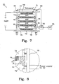
- FIG. 7 shows an assembled battery stack 71 with a third embodiment of a circuit-breaking system 70.
- the system further comprises a control unit 72, and an impact recognition device 73.
- the battery stack 71 comprises four bipolar batteries 74 and the pressure over the bipolar batteries is maintained using tie rods 75.
- Each bipolar battery 74 comprises at least one battery cell connected to a positive endplate and a negative endplate, and each battery has in this embodiment a nominal voltage of 60 Volts between the positive and the negative endplate.
- the assembled battery stack 71 has a nominal voltage of 240 Volts at the battery stack terminals 77, 78.
- the four bipolar batteries 74 are connected in series between the positive stack terminal 77 and the negative stack terminal 78 using electrically conductive spacing elements 76 in the shape of meander shaped folded plates, as shown in figure 7 .
- a pressure over the battery stack 71 is maintained by providing rigid plates 79 on either side of the battery stack 71 through which the tie rods 75 are tightened.
- Each plate 79 is placed adjacently to one of the battery stack terminals 77 and 78, as previously described in connection with figure 4 .
- a battery stack arrangement as shown in figure 7 , has been described in a co-pending Swedish patent application SE 0600100-2 , assigned to the present applicant, in which further details regarding the actual design of the battery stack may be obtained.
- the impact recognition device 73 sends a signal to the control unit 72 when an impact is detected, as explained above.
- the control unit 72 which in this embodiment is powered directly from one of the bipolar batteries 74 in the battery stack 71 to further secure the supply of power to the control unit 72 in case of an accident, activates an interrupt mechanism which is arranged to break the electric circuit in the battery stack 71.
- the interrupt mechanism comprises in this embodiment of only one controlled mechanism that will remove the pressure over the battery stack 71, and as a result of this the electric circuit is broken by the built-in expanding properties of at least one device inserted between each adjacent bipolar battery 74 that will separate the bipolar batteries 74 from each other.
- the controlled mechanism comprises, as described above explosive bolts 80 (also called pyrotechnic fasteners) which are incorporated in the tie rods 75 that can be initiated by a remote command.
- the device with the built-in expanding properties could be implemented, as illustrated in figure 7 , as at least one compressed elastic member 81. Further possible implementations include compressed springs, or any other material with expanding properties.
- the folded plate 76 is preferably attached to the battery endplate of one of the bipolar batteries 74 using a conductive adhesive, see figure 8 .
Landscapes
- Engineering & Computer Science (AREA)
- Chemical & Material Sciences (AREA)
- General Chemical & Material Sciences (AREA)
- Chemical Kinetics & Catalysis (AREA)
- Electrochemistry (AREA)
- Mechanical Engineering (AREA)
- Transportation (AREA)
- Power Engineering (AREA)
- Life Sciences & Earth Sciences (AREA)
- Sustainable Development (AREA)
- Sustainable Energy (AREA)
- Manufacturing & Machinery (AREA)
- Aviation & Aerospace Engineering (AREA)
- Combustion & Propulsion (AREA)
- Connection Of Batteries Or Terminals (AREA)
- Secondary Cells (AREA)
- Electric Propulsion And Braking For Vehicles (AREA)
- Battery Mounting, Suspending (AREA)
- Hybrid Cells (AREA)
Abstract
Description
- The present invention relates to a system for reducing the power in a battery stack arrangement, especially intended for bipolar batteries in electrically powered vehicles (EPV), or hybrid electrical vehicles (HEV), for reasons of enhanced safety.
- Batteries used in high power applications, such as vehicle applications, normally are arranged in a battery stack which comprises a plurality of batteries connected in series, or in parallel, held together using a rigid frame. This frame usually comprises end pieces interconnected with tie rods, wherein a desired pressure over the battery stack is maintained during operation.
- The battery stack could be designed to a voltage between 60 and 300 Volts, and the amount of energy stored in the battery stack is harmful, and even lethal, to a person if exposed to it by mistake. If the battery stack is involved in an accident, terminals of the battery stack may become accessible and when this occurs a person is in danger of being exposed to the energy stored within the battery stack.
- A hybrid electrical vehicle (HEV) or an electrically power vehicle (EPV) contain a battery stack as discussed above. During an accident, it is possible that the terminals of the battery stack are coupled to the chassis of the vehicle and thus endangering rescue personnel when touching the vehicle. This is an unacceptable situation and measures need to be taken to avoid this from happening.
- A solution to the problem is to manufacture battery enclosures that can withstand an impact during an accident. However, this is expensive and will increase the weight of the battery stack arrangement.
- In
JP 09 284904 - The object with the present invention is to provide a system that will reduce the possibility of exposing a person to stored energy within a battery stack provided in a vehicle when the vehicle is subject to an accident.
- A solution to this object is a system that will break the electric circuit in the battery stack provided in the vehicle. An impact recognition device detects that an impact has taken place, such as an accident. One or more interrupt mechanisms will thereafter divide the battery stack into battery sub-stacks as a result of the detected impact by the impact recognition device. Each battery sub-stack will have a reduced energy storage capacity and will thereby reduce the risk for injuring a person that unintentionally is exposed to the energy in one sub-stack.
- An advantage with the present invention is that rescue personnel may approach a vehicle that contain high power battery stack reducing the risk to such personnel.
- Still another advantage is that tools needed to remove persons stuck in a vehicle can be used without having to remove the battery stack from the vehicle before commencing the rescue operation.
- A further advantage, in a preferred embodiment, is that one or more of the battery sub-stack from a battery stack that has been separated may be reused in a rebuilt battery stack.
- Further advantages will be apparent to a skilled person in the art from the following detailed description.
-
-
Figure 1 shows a prior art embodiment of a circuit-breaking system for a battery stack. -
Figure 2 shows an assembled battery stack with a first embodiment of a circuit-breaking system. -
Figures 3a and 3b show different embodiments of interrupt mechanisms used in the circuit-breaking system infigure 2 -
Figure 3c shows an enlarged portion of the circuit-breaking system infigure 2 when the circuit-breaking system has been activated. -
Figure 4 shows an assembled battery stack with a second embodiment of a circuit-breaking system. -
Figure 5 shows an enlarged portion of the battery stack infigure 4 when the circuit-breaking system has been activated. -
Figure 6 illustrates a circuit-breaking system implemented in a vehicle. -
Figure 7 shows an assembled battery stack with a third embodiment of a circuit-breaking system. -
Figure 8 shows an enlarged portion of the battery stack infigure 7 when the circuit-breaking system has been activated. - The present invention is intended to be a safety device for use in a vehicle, wherein the electric circuit in a battery stack comprising a plurality of batteries, preferably bipolar batteries, is configured to break and divide the battery stack into a number of sub-stacks when an actuator is trigged. The sub-stack comprises one or more batteries, and the actuator is preferably implemented as an impact recognition device, similar to a device that will trigger airbags in a vehicle to inflate in case of an accident. The amount of energy needed to break the electric circuit is stored within the inventive system in different forms as will be described in connection with the embodiments of the invention.
-
Figure 1 shows aprior art system 10 comprising abattery stack 11, a control unit (CU) 12 and an impact recognition device (IR) 13. Thebattery stack 11 comprises in this embodiment fivebatteries 14 comprising at least one battery cell (not shown) connected to apositive terminal 15 and anegative terminal 16, and each battery has a nominal voltage of 12-60 Volts between the positive and the negative terminal. The assembled battery stack has a nominal voltage of 60-300 Volts at thebattery stack terminals - The five batteries are connected in series by connecting the positive terminal of one battery with the negative terminal of an adjacent battery via an
electric circuit breaker 19, as shown infigure 1 . Theimpact recognition device 13 sends a signal to thecontrol unit 12 when an impact, e.g. cause by an accident, is detected. Thecontrol unit 12 activates an interrupt mechanism which is arranged to break the electric circuit in the battery stack. The interrupt mechanism comprises in this embodiment theelectric circuit breaker 19, preferably designed in such a way that the electric circuit between two adjacent batteries is maintained provided a control signal from thecontrol unit 12 is present. If an impact is detected, thecontrol unit 12 will cease to send out the control signal and theelectric circuit breaker 19 will break the connection between the terminals. Thebattery stack 11 will be divided into five sub-stacks, each comprising only onebattery 14, and the electric circuit in thebattery stack 11 will break. - It should be noted that the preferred interrupt mechanism described above, which is readily available for a skilled person in the art, has the advantage that a malfunction in the
control unit 12, e.g. loss of supply voltage, will automatically break the electric circuit in thebattery stack 11, but the electric circuit may be restored by activating the control signal sent from thecontrol unit 12. -
Figure 2 shows a first embodiment of asystem 20 for breaking an electric circuit in abattery stack 21. The system further comprises acontrol unit 22, and animpact recognition device 23. Thebattery stack 21 comprises sixbipolar batteries 24 and the pressure over the bipolar batteries is maintained usingtie rods 25. Eachbipolar battery 24 comprises at least one battery cell connected to a positive endplate and a negative endplate, and each battery has in this embodiment a nominal voltage of 24 Volts between the positive and the negative endplate. The endplates in a bipolar battery has the same function as the battery terminals described in connection withfigure 1 . The assembledbattery stack 21 has a nominal voltage of 144 Volts at thebattery stack terminals - The six
bipolar batteries 24 are connected in series between thepositive stack terminal 27 and thenegative stack terminal 28 using electricallyconductive spacing elements 26 in the shape of folded plates, as shown infigure 2 . Thetie rods 25 could either be made from an insulating material, or be fastened in an insulating manner to thebattery stack terminals - The present invention is directed towards an interrupt mechanism to break to electric circuit and divide the battery stack into sub-stacks, and not towards the battery stack arrangement as shown in
figure 2 , which has been described in a co-pending Swedish patent applicationSE 0600100-2 alignment guides 29 in each battery casing are attached to prevent the bipolar batteries to move in relation to each other. - The
impact recognition device 23 sends a signal to thecontrol unit 22 when an impact is detected, as explained above. Thecontrol unit 22 activates aninterrupt mechanism 30 which is arranged to break the electric circuit in the battery stack. The interrupt mechanism is in this embodiment electromechanically activated, as shown in more detail infigures 3a and 3b . Theinterrupt mechanism 30 acts on thetie rods 25 and breaks each tie rod into several parts and the pressure created by the tie rods over the bipolar batteries is removed.Helical springs 31 are released from a compressed state and will push batteries away from each other and a distance "w" will appear between the battery terminal of abipolar battery 24 and an electricallyconductive spacing element 26, which preferably is attached to the battery endplate on an adjacentbipolar battery 24 using a conductive adhesive, seefigure 3c . - In this embodiment, the
interrupt mechanism 30 will break eachtie rod 25 at two positions andsprings 31 will separate the battery stack in such a way that three sub-stacks, each comprising two bipolar batteries, are created when theimpact recognition device 23 detects an impact. -
Figure 3a shows a partial cross-sectional view of a first embodiment of an interruptmechanism 30 used in connection with the system described infigure 2 . The interruptmechanism 30 comprises apin 32, aspring 33, amechanical latch 34 and asolenoid 35. Thespring 33 is compressed in an activated state and acts on thepin 32. Thepin 32 is provided with a groove in which amechanical latch 34 is inserted to hold thepin 32 in an activated position. When thesolenoid 35 receives a control signal from thecontrol unit 22, the latch is withdrawn from the groove in the direction ofarrow 36 and thepin 32 is released from its activated position and moves forward in the direction ofarrow 37 and break thetie rod 25. - In
figure 3b an alternative embodiment is described wherein asolenoid 38 is controlled by a control signal from thecontrol unit 22 and moves thepin 32 forward in the direction ofarrow 39 and break thetie rod 25. - The solenoid is preferably implemented as a loop of wire wrapped around a metallic core, which produces a magnetic field when an electrical current is passed through it. The strength of the magnetic field can be controlled and the solenoid may be used as electromagnets. The purpose of the solenoid is to convert energy into a linear motion, and the operation and construction of solenoids are known to a skilled person in the art and will thus not be described in more detail.
- It should be noted that in order to perform the invention and reduce the power in a battery stack being held together with a tie rod arrangement, as illustrated in connection with
figure 2 , only one of the interrupt mechanisms along the length of each tie rod is necessary. The reasons for having a multiple of interrupt mechanisms are, except for the safety by redundancy, to ensure that created the sub-stacks will not have more than a predetermined amount of power. -
Figure 4 shows an assembledbattery stack 41 with a second embodiment of a circuit-breakingsystem 40. The system further comprises acontrol unit 42, and animpact recognition device 43. Thebattery stack 41 comprises fourbipolar batteries 44 and the pressure over the bipolar batteries is maintained usingtie rods 45. Eachbipolar battery 44 comprises at least one battery cell connected to a positive endplate and a negative endplate, and each battery has in this embodiment a nominal voltage of 60 Volts between the positive and the negative endplate. The assembledbattery stack 41 has a nominal voltage of 240 Volts at thebattery stack terminals - The four
bipolar batteries 44 are connected in series between thepositive stack terminal 47 and thenegative stack terminal 48 using electricallyconductive spacing elements 46 in the shape of pins, as shown infigure 4 . A pressure over thebattery stack 41 is maintained by providingrigid plates 49 on either side of thebattery stack 41 through which thetie rods 45 are tightened. Eachplate 49 is placed adjacently to one of thebattery stack terminals tie rods 45 could either be made from an insulating (non-conductive) material, or be fastened in an insulating manner to theplates 49 to prevent a short circuit connection between thebattery stack terminals tie rods 45 could be made from any type of material, preferably a metallic material. - As mentioned above, the present invention is directed towards an interrupt mechanism to break to electric circuit and divide the battery stack into sub-stacks, and not towards the battery stack arrangement as shown in
figure 4 , which has been described in a co-pending Swedish patent applicationSE 0600100-2 bipolar batteries 44 to move in relation to each other. - The
impact recognition device 43 sends a signal to thecontrol unit 42 when an impact is detected, as explained above. Thecontrol unit 42 activates an interrupt mechanism which is arranged to break the electric circuit in thebattery stack 41. The interrupt mechanism comprises in this embodiment of two independently controlled mechanisms. The first mechanism will remove the pressure over the battery stack, and the second mechanism will break the electric circuit by separating thebipolar batteries 44 from each other. - The first mechanism comprises explosive bolts 50 (also called pyrotechnic fasteners) which are incorporated in the
tie rods 45 that can be initiated by a remote command. Explosive charges embedded within the bolts and activated (precisely controlled) by an electric current ("Detonate" signal) from thecontrol unit 42 instantly break the bolt into two or three pieces. The bolt is typically scored around its circumference at the point(s) where the severance should occur. Upon detonation a selected part of the fastener rapidly disassembles without producing any shrapnel or fragments, freeing the matedplates 49 from each other. Explosive bolts are lighter and far more reliable than mechanical latches. The term pyrotechnic fastener may naturally also include a nut within which two pyrotechnical charges may be arranged that splits the nut into two pieces when activated. - When the pressure over the
battery stack 41 is removed, the second mechanism, inflating air bags, is activated. Airbag inflating units 51 are provided between two adjacentbipolar batteries 44 in such a way that whenairbags 52 are inflated, as illustrated infigure 5 , they will move apart as indicated by thearrows bipolar batteries 44, and thus the electric circuit in the battery stack is broken. Thepins 46 are preferably attached to the battery endplate of one of thebipolar batteries 44 using a conductive adhesive, seefigure 5 . - The air
bag inflating units 51 are well known in the prior art, wherein an electronic control signal "Fill the airbags" will release a gas that will inflate the air bags to conduct the function described above. In an alternative embodiment, one airbag inflating unit 51 may be used for inflating several, or all, present air bags in the system to ensure more or less simultaneousinflated air bags 52. -
Figure 6 illustrates a circuit-breakingsystem 60 to break the electric circuit in abattery stack 61 implemented in avehicle 59. Thecircuit breaking system 60 comprises acontrol unit 62, animpact recognition device 63, and an interrupt mechanism (which is built into the battery stack 61) according to any of the described embodiment above. Thevehicle 59 is a hybrid electrical vehicle (HEV), or an electrically power vehicle (EPV), containing abattery stack 61 for providing energy to anengine 64. Thesystem 60 further comprises the optional features: anindicator 65 that will indicate that the interrupt mechanism in thecircuit breaking system 60 has been activated; and a manually release 66 provided in theimpact recognition device 63, whereby the breaking of the electric circuit in thebattery stack 61 may be manually operated. -
Figure 7 shows an assembledbattery stack 71 with a third embodiment of a circuit-breakingsystem 70. The system further comprises acontrol unit 72, and animpact recognition device 73. Thebattery stack 71 comprises fourbipolar batteries 74 and the pressure over the bipolar batteries is maintained usingtie rods 75. Eachbipolar battery 74 comprises at least one battery cell connected to a positive endplate and a negative endplate, and each battery has in this embodiment a nominal voltage of 60 Volts between the positive and the negative endplate. The assembledbattery stack 71 has a nominal voltage of 240 Volts at thebattery stack terminals - The four
bipolar batteries 74 are connected in series between thepositive stack terminal 77 and thenegative stack terminal 78 using electricallyconductive spacing elements 76 in the shape of meander shaped folded plates, as shown infigure 7 . A pressure over thebattery stack 71 is maintained by providingrigid plates 79 on either side of thebattery stack 71 through which thetie rods 75 are tightened. Eachplate 79 is placed adjacently to one of thebattery stack terminals figure 4 . - A battery stack arrangement, as shown in
figure 7 , has been described in a co-pending Swedish patent applicationSE 0600100-2 - The
impact recognition device 73 sends a signal to thecontrol unit 72 when an impact is detected, as explained above. Thecontrol unit 72, which in this embodiment is powered directly from one of thebipolar batteries 74 in thebattery stack 71 to further secure the supply of power to thecontrol unit 72 in case of an accident, activates an interrupt mechanism which is arranged to break the electric circuit in thebattery stack 71. The interrupt mechanism comprises in this embodiment of only one controlled mechanism that will remove the pressure over thebattery stack 71, and as a result of this the electric circuit is broken by the built-in expanding properties of at least one device inserted between each adjacentbipolar battery 74 that will separate thebipolar batteries 74 from each other. - The controlled mechanism comprises, as described above explosive bolts 80 (also called pyrotechnic fasteners) which are incorporated in the
tie rods 75 that can be initiated by a remote command. The device with the built-in expanding properties could be implemented, as illustrated infigure 7 , as at least one compressedelastic member 81. Further possible implementations include compressed springs, or any other material with expanding properties. - When the pressure over the
battery stack 71 is removed, theelastic member 81 will strive to regain its uncompressed shape. When doing so two adjacentbipolar batteries 74 will move apart as indicated by thearrows figure 8 . A distance "w" will appear between thebipolar batteries 74, and thus the electric circuit in the battery stack is broken. The foldedplate 76 is preferably attached to the battery endplate of one of thebipolar batteries 74 using a conductive adhesive, seefigure 8 .
Claims (13)
- A system (20; 40; 60; 70) for breaking an electric circuit in a battery stack (21; 41; 61; 71) arranged in a vehicle (59), wherein said battery stack comprises a plurality of batteries (24; 44; 74), each battery comprises at least one battery cell connected to a positive terminal and a negative terminal, wherein an electric current flows between the positive terminal and a negative terminal of adjacently arranged batteries during operation, said system comprises- an impact recognition device (23; 43; 63; 73) connected to a control unit (22; 42; 62; 72), and- at least one interrupt mechanism (30; 50, 51; 80 ) which is controlled by said control unit (22; 42; 62; 72) and arranged to break the electric circuit in the battery stack (21; 41; 61; 71) to divide said battery stack into several battery sub-stacks when said impact recognition device (23; 43; 63; 73) detects an impact, characterized in that said batteries are bipolar batteries and said battery sub-stacks comprises at least one bipolar battery (24; 44; 74), wherein pressure over the bipolar batteries (24; 44; 74) in the battery stack (21; 41; 71) is maintained using one or more tie rods (25; 45; 75) to keep said electric circuit in the battery stack, and the interrupt mechanism (30; 50; 80) is configured to remove the pressure created by the tie rods (25; 45; 75) to break said electric circuit in the battery stack when the impact recognition device (23; 43; 73) detects an impact, and the interrupt mechanism further comprises an expanding unit (31; 51, 52; 81) configured to separate and to move the sub-stacks apart causing a distance "w" to appear between adjacent battery sub-stacks when the pressure is removed.
- The system according to claim 1, wherein the interrupt mechanism further comprises a pyrotechnical fastener (50; 80) which is activated when the impact recognition device (43; 73) detects an impact to initiate the separation process by removing the pressure created by the tie rods (45; 75).
- The system according to any of claims 1-2, wherein the expanding unit comprises one or more devices having a built-in spring force.
- The system according to claim 3, wherein said device is a helical spring (31) which is compressed before the impact recognition device (23) is activated.
- The system according to claim 3, wherein said device is an elastic member (81) which is compressed before the impact recognition device (73) is activated.
- The system according to any of claims 1-2, wherein the expanding unit comprises one or more airbags (51, 52).
- The system according to any of claims 1-6, wherein the positive terminal and the negative terminal of each bipolar battery is a positive endplate and a negative endplate, respectively, and the electric current flows laterally through an intermediate electrically conductive spacing element (26; 46; 76) arranged between the positive endplate and an adjacently arranged negative endplate.
- The system according to claim 7, wherein the spacing element (26; 46; 76) is conductively secured to one of the positive or the adjacently arranged negative endplate in the battery stack (21; 41; 71).
- The system according to any of claims 1-8, wherein said impact recognition device (63) is provided with a manual release (66), whereby the breaking of the electric circuit in the battery stack (61) may be manually operated.
- The system according to any of claims 1-9, wherein said system further is provided with an indicator (65), which indicator indicates if any of said interrupt mechanism has been activated.
- A vehicle (59) provided with an electrically power engine (64), a battery stack (61) comprising a plurality of batteries (24; 44; 74), an impact recognition device (63), an interrupt mechanism which is arranged to break the electric circuit in the battery stack (61) to divide said battery stack into several battery sub-stacks when said impact recognition device (63) detects an impact, characterized in that said batteries are bipolar batteries, said battery sub-stacks comprises at least one bipolar battery, said vehicle is further provided with a system for breaking an electric circuit in the battery stack (61) as defined in any of claims 1-10, and tie rods (25; 45; 75) to maintain pressure over the bipolar batteries (24; 44; 74) and to keep an electric circuit in the battery stack (21; 41; 71) and the interrupt mechanism (30; 50; 80) is configured to remove the pressure created by the tie rods (25; 45; 75) to break the electric circuit in the battery stack when the impact recognition device (23; 43; 73) detects an impact, and the interrupt mechanism further comprises an expanding unit configured to separate and to move the sub-stacks apart causing a distance "w" to appear between adjacent battery sub-stacks when the pressure is removed.
- The vehicle according to claim 11, wherein said impact recognition device (63) is provided with a manual release (66), whereby the breaking of the electric circuit in the battery stack (61) may be manually operated.
- The vehicle according to any of claims 11-12, wherein said vehicle (59) further is provided with an indicator (65), which indicator indicates if any of said interrupt mechanism has been activated.
Applications Claiming Priority (2)
| Application Number | Priority Date | Filing Date | Title |
|---|---|---|---|
| SE0602739A SE0602739L (en) | 2006-12-18 | 2006-12-18 | A system for reducing power in a battery stack arrangement, and a vehicle equipped with such a system |
| PCT/SE2007/001112 WO2008076040A1 (en) | 2006-12-18 | 2007-12-17 | A system for reducing the power in a battery stack arrangement |
Publications (2)
| Publication Number | Publication Date |
|---|---|
| EP2094523A1 EP2094523A1 (en) | 2009-09-02 |
| EP2094523B1 true EP2094523B1 (en) | 2010-11-03 |
Family
ID=39185756
Family Applications (1)
| Application Number | Title | Priority Date | Filing Date |
|---|---|---|---|
| EP07852114A Active EP2094523B1 (en) | 2006-12-18 | 2007-12-17 | A system for reducing the power in a battery stack arrangement |
Country Status (5)
| Country | Link |
|---|---|
| EP (1) | EP2094523B1 (en) |
| AT (1) | ATE486742T1 (en) |
| DE (1) | DE602007010345D1 (en) |
| SE (1) | SE0602739L (en) |
| WO (1) | WO2008076040A1 (en) |
Families Citing this family (20)
| Publication number | Priority date | Publication date | Assignee | Title |
|---|---|---|---|---|
| DE102008050872B4 (en) * | 2008-09-29 | 2020-07-30 | Volkswagen Ag | Protective device for an electrical store |
| EP2219246A1 (en) * | 2009-02-10 | 2010-08-18 | Autoliv Development AB | A safety arrangement for a motor vehicle |
| GB0913345D0 (en) | 2009-07-31 | 2009-09-16 | Astrazeneca Ab | New combination 802 |
| DE102009050996A1 (en) * | 2009-10-28 | 2011-05-12 | Volkswagen Ag | Shutdown or separation of an energy storage |
| GB2475326A (en) * | 2009-11-16 | 2011-05-18 | Autoliv Dev | Inflatable battery protector |
| DE102010037176B4 (en) * | 2010-08-26 | 2024-05-16 | Dr. Ing. H.C. F. Porsche Aktiengesellschaft | Electrical energy storage device with safety function and method for reducing electrical output voltage values of an electrical energy storage device |
| AT510815B1 (en) * | 2010-11-17 | 2014-06-15 | Avl List Gmbh | MOUNTING DEVICE FOR AT LEAST ONE BATTERY MODULE |
| GB201021992D0 (en) | 2010-12-23 | 2011-02-02 | Astrazeneca Ab | Compound |
| GB201021979D0 (en) | 2010-12-23 | 2011-02-02 | Astrazeneca Ab | New compound |
| WO2017162213A1 (en) * | 2016-03-25 | 2017-09-28 | 安徽巨大电池技术有限公司 | Battery pack and assembly method therefor |
| JP6565940B2 (en) * | 2017-01-17 | 2019-08-28 | トヨタ自動車株式会社 | vehicle |
| DE102017206358A1 (en) | 2017-04-12 | 2018-10-18 | VW-VM Forschungsgesellschaft mbH & Co. KG | Modular battery with improved safety features |
| EP3435466A1 (en) * | 2017-07-24 | 2019-01-30 | Robert Bosch GmbH | Safety device, safety system, safeguarded battery unit and method for decreasing the total power output of a battery element |
| US11465445B2 (en) | 2019-06-05 | 2022-10-11 | Avl Powertrain Engineering, Inc. | Vehicle axle assembly |
| CN114041231A (en) * | 2019-06-05 | 2022-02-11 | Avl动力工程公司 | Vehicle frame and power supply assembly and related systems and methods |
| JP7337961B2 (en) | 2019-06-05 | 2023-09-04 | エーヴィーエル パワートレイン エンジニアリング インコーポレイテッド | Vehicle frame assembly and power tray |
| US11843097B2 (en) | 2019-09-10 | 2023-12-12 | Avl Powertrain Engineering, Inc. | Power supply control systems and methods |
| US11833913B2 (en) | 2021-07-12 | 2023-12-05 | Beta Air, Llc | System and method for disconnecting a battery assembly from an electric aircraft |
| CN113904070B (en) * | 2021-09-30 | 2024-02-20 | 安徽和鼎机电设备有限公司 | Lithium battery box electric leakage safety protection equipment |
| US20250357526A1 (en) | 2024-05-15 | 2025-11-20 | GM Global Technology Operations LLC | Systems and methods for thermal management of a battery module |
Family Cites Families (6)
| Publication number | Priority date | Publication date | Assignee | Title |
|---|---|---|---|---|
| JP2819828B2 (en) * | 1990-11-30 | 1998-11-05 | 日産自動車株式会社 | Electric vehicle power supply |
| JP3173244B2 (en) * | 1993-08-12 | 2001-06-04 | 富士電機株式会社 | Electric vehicle electric system |
| JP3076489B2 (en) * | 1993-12-15 | 2000-08-14 | 株式会社東芝 | Electric car |
| JPH09284904A (en) | 1996-04-05 | 1997-10-31 | Toyota Motor Corp | Vehicle safety equipment |
| US6547020B2 (en) * | 2001-05-04 | 2003-04-15 | International Truck Intellectual Property Company, L.L.C. | Battery mounting assembly |
| KR100612305B1 (en) * | 2004-06-25 | 2006-08-11 | 삼성에스디아이 주식회사 | Battery module |
-
2006
- 2006-12-18 SE SE0602739A patent/SE0602739L/en unknown
-
2007
- 2007-12-17 EP EP07852114A patent/EP2094523B1/en active Active
- 2007-12-17 AT AT07852114T patent/ATE486742T1/en not_active IP Right Cessation
- 2007-12-17 WO PCT/SE2007/001112 patent/WO2008076040A1/en not_active Ceased
- 2007-12-17 DE DE602007010345T patent/DE602007010345D1/en active Active
Also Published As
| Publication number | Publication date |
|---|---|
| EP2094523A1 (en) | 2009-09-02 |
| WO2008076040A1 (en) | 2008-06-26 |
| SE530201C2 (en) | 2008-03-25 |
| ATE486742T1 (en) | 2010-11-15 |
| SE0602739L (en) | 2008-03-25 |
| DE602007010345D1 (en) | 2010-12-16 |
Similar Documents
| Publication | Publication Date | Title |
|---|---|---|
| EP2094523B1 (en) | A system for reducing the power in a battery stack arrangement | |
| US9368783B2 (en) | Battery pack for a vehicle | |
| DE102015204028B4 (en) | High voltage interruption for electric vehicles | |
| EP2494639B1 (en) | Deactivation or disconnection of an energy store | |
| US20040041682A1 (en) | Battery circuit disconnect device | |
| US20130056344A1 (en) | Electric circuit breaker with pyrotechnic actuation | |
| DE102020125293A1 (en) | FLOATING RELEASE MECHANISMS FOR USE WITH SWITCHING DEVICES INCLUDING PYROTECHNICAL FEATURES | |
| CN111587469A (en) | pyrotechnic switch | |
| CN109070756A (en) | High voltage battery system including fuse | |
| EP2219246A1 (en) | A safety arrangement for a motor vehicle | |
| DE102013017409A1 (en) | Battery system for electromotive drivable vehicle i.e. hybrid vehicle, has battery management system providing signal for triggering safety device when pole of battery of high voltage electrical system and/or motor drivers is disconnected | |
| KR20230093006A (en) | Smart Connect Seats, Battery Packs and Vehicles | |
| JP2007091034A (en) | Power source device for vehicle | |
| CN103999181B (en) | For disconnecting the pyrotechnics separating element of the high-voltage path in motor vehicles | |
| EP2543534A1 (en) | Energy storage device with improved security, automobile with a respective energy storage device and method for operating an energy storage device | |
| KR102027062B1 (en) | Stage separation system of a launch vehicle | |
| CN111194472A (en) | Electrical system | |
| EP2490241A1 (en) | Interrupter device for interrupting current flow in a current path and supply circuit of an electric or hybrid-electric power train for a vehicle including such an interrupter device | |
| CN112959890A (en) | Electric automobile collision fast power-off device | |
| DE102024118097A1 (en) | Battery arrangement and method for cutting a circuit part of a battery | |
| DE102012010872A1 (en) | Battery system for use in shut-off device that is utilized for disconnection of pole of battery from battery module of e.g. vehicle, has detecting unit connected with releasing unit for interruption of source between pole and module | |
| JP2014040200A (en) | Inflator and airbag system using the same |
Legal Events
| Date | Code | Title | Description |
|---|---|---|---|
| PUAI | Public reference made under article 153(3) epc to a published international application that has entered the european phase |
Free format text: ORIGINAL CODE: 0009012 |
|
| 17P | Request for examination filed |
Effective date: 20090720 |
|
| AK | Designated contracting states |
Kind code of ref document: A1 Designated state(s): AT BE BG CH CY CZ DE DK EE ES FI FR GB GR HU IE IS IT LI LT LU LV MC MT NL PL PT RO SE SI SK TR |
|
| 17Q | First examination report despatched |
Effective date: 20091116 |
|
| DAX | Request for extension of the european patent (deleted) | ||
| GRAP | Despatch of communication of intention to grant a patent |
Free format text: ORIGINAL CODE: EPIDOSNIGR1 |
|
| GRAS | Grant fee paid |
Free format text: ORIGINAL CODE: EPIDOSNIGR3 |
|
| GRAA | (expected) grant |
Free format text: ORIGINAL CODE: 0009210 |
|
| AK | Designated contracting states |
Kind code of ref document: B1 Designated state(s): AT BE BG CH CY CZ DE DK EE ES FI FR GB GR HU IE IS IT LI LT LU LV MC MT NL PL PT RO SE SI SK TR |
|
| REG | Reference to a national code |
Ref country code: GB Ref legal event code: FG4D |
|
| REG | Reference to a national code |
Ref country code: CH Ref legal event code: EP |
|
| REG | Reference to a national code |
Ref country code: IE Ref legal event code: FG4D |
|
| REF | Corresponds to: |
Ref document number: 602007010345 Country of ref document: DE Date of ref document: 20101216 Kind code of ref document: P |
|
| REG | Reference to a national code |
Ref country code: NL Ref legal event code: VDEP Effective date: 20101103 |
|
| REG | Reference to a national code |
Ref country code: CH Ref legal event code: NV Representative=s name: OFFICE ERNEST T. FREYLINGER S.A. |
|
| LTIE | Lt: invalidation of european patent or patent extension |
Effective date: 20101103 |
|
| PG25 | Lapsed in a contracting state [announced via postgrant information from national office to epo] |
Ref country code: LT Free format text: LAPSE BECAUSE OF FAILURE TO SUBMIT A TRANSLATION OF THE DESCRIPTION OR TO PAY THE FEE WITHIN THE PRESCRIBED TIME-LIMIT Effective date: 20101103 |
|
| PG25 | Lapsed in a contracting state [announced via postgrant information from national office to epo] |
Ref country code: SE Free format text: LAPSE BECAUSE OF FAILURE TO SUBMIT A TRANSLATION OF THE DESCRIPTION OR TO PAY THE FEE WITHIN THE PRESCRIBED TIME-LIMIT Effective date: 20101103 Ref country code: PT Free format text: LAPSE BECAUSE OF FAILURE TO SUBMIT A TRANSLATION OF THE DESCRIPTION OR TO PAY THE FEE WITHIN THE PRESCRIBED TIME-LIMIT Effective date: 20110303 Ref country code: BG Free format text: LAPSE BECAUSE OF FAILURE TO SUBMIT A TRANSLATION OF THE DESCRIPTION OR TO PAY THE FEE WITHIN THE PRESCRIBED TIME-LIMIT Effective date: 20110203 Ref country code: AT Free format text: LAPSE BECAUSE OF FAILURE TO SUBMIT A TRANSLATION OF THE DESCRIPTION OR TO PAY THE FEE WITHIN THE PRESCRIBED TIME-LIMIT Effective date: 20101103 Ref country code: FI Free format text: LAPSE BECAUSE OF FAILURE TO SUBMIT A TRANSLATION OF THE DESCRIPTION OR TO PAY THE FEE WITHIN THE PRESCRIBED TIME-LIMIT Effective date: 20101103 Ref country code: IS Free format text: LAPSE BECAUSE OF FAILURE TO SUBMIT A TRANSLATION OF THE DESCRIPTION OR TO PAY THE FEE WITHIN THE PRESCRIBED TIME-LIMIT Effective date: 20110303 Ref country code: NL Free format text: LAPSE BECAUSE OF FAILURE TO SUBMIT A TRANSLATION OF THE DESCRIPTION OR TO PAY THE FEE WITHIN THE PRESCRIBED TIME-LIMIT Effective date: 20101103 Ref country code: LV Free format text: LAPSE BECAUSE OF FAILURE TO SUBMIT A TRANSLATION OF THE DESCRIPTION OR TO PAY THE FEE WITHIN THE PRESCRIBED TIME-LIMIT Effective date: 20101103 Ref country code: SI Free format text: LAPSE BECAUSE OF FAILURE TO SUBMIT A TRANSLATION OF THE DESCRIPTION OR TO PAY THE FEE WITHIN THE PRESCRIBED TIME-LIMIT Effective date: 20101103 |
|
| PG25 | Lapsed in a contracting state [announced via postgrant information from national office to epo] |
Ref country code: GR Free format text: LAPSE BECAUSE OF FAILURE TO SUBMIT A TRANSLATION OF THE DESCRIPTION OR TO PAY THE FEE WITHIN THE PRESCRIBED TIME-LIMIT Effective date: 20110204 |
|
| PG25 | Lapsed in a contracting state [announced via postgrant information from national office to epo] |
Ref country code: ES Free format text: LAPSE BECAUSE OF FAILURE TO SUBMIT A TRANSLATION OF THE DESCRIPTION OR TO PAY THE FEE WITHIN THE PRESCRIBED TIME-LIMIT Effective date: 20110214 Ref country code: BE Free format text: LAPSE BECAUSE OF FAILURE TO SUBMIT A TRANSLATION OF THE DESCRIPTION OR TO PAY THE FEE WITHIN THE PRESCRIBED TIME-LIMIT Effective date: 20101103 Ref country code: CZ Free format text: LAPSE BECAUSE OF FAILURE TO SUBMIT A TRANSLATION OF THE DESCRIPTION OR TO PAY THE FEE WITHIN THE PRESCRIBED TIME-LIMIT Effective date: 20101103 Ref country code: EE Free format text: LAPSE BECAUSE OF FAILURE TO SUBMIT A TRANSLATION OF THE DESCRIPTION OR TO PAY THE FEE WITHIN THE PRESCRIBED TIME-LIMIT Effective date: 20101103 Ref country code: MC Free format text: LAPSE BECAUSE OF NON-PAYMENT OF DUE FEES Effective date: 20101231 |
|
| PG25 | Lapsed in a contracting state [announced via postgrant information from national office to epo] |
Ref country code: SK Free format text: LAPSE BECAUSE OF FAILURE TO SUBMIT A TRANSLATION OF THE DESCRIPTION OR TO PAY THE FEE WITHIN THE PRESCRIBED TIME-LIMIT Effective date: 20101103 Ref country code: DK Free format text: LAPSE BECAUSE OF FAILURE TO SUBMIT A TRANSLATION OF THE DESCRIPTION OR TO PAY THE FEE WITHIN THE PRESCRIBED TIME-LIMIT Effective date: 20101103 Ref country code: RO Free format text: LAPSE BECAUSE OF FAILURE TO SUBMIT A TRANSLATION OF THE DESCRIPTION OR TO PAY THE FEE WITHIN THE PRESCRIBED TIME-LIMIT Effective date: 20101103 Ref country code: PL Free format text: LAPSE BECAUSE OF FAILURE TO SUBMIT A TRANSLATION OF THE DESCRIPTION OR TO PAY THE FEE WITHIN THE PRESCRIBED TIME-LIMIT Effective date: 20101103 |
|
| PLBE | No opposition filed within time limit |
Free format text: ORIGINAL CODE: 0009261 |
|
| STAA | Information on the status of an ep patent application or granted ep patent |
Free format text: STATUS: NO OPPOSITION FILED WITHIN TIME LIMIT |
|
| 26N | No opposition filed |
Effective date: 20110804 |
|
| PG25 | Lapsed in a contracting state [announced via postgrant information from national office to epo] |
Ref country code: IE Free format text: LAPSE BECAUSE OF NON-PAYMENT OF DUE FEES Effective date: 20101217 |
|
| REG | Reference to a national code |
Ref country code: DE Ref legal event code: R097 Ref document number: 602007010345 Country of ref document: DE Effective date: 20110804 |
|
| PG25 | Lapsed in a contracting state [announced via postgrant information from national office to epo] |
Ref country code: MT Free format text: LAPSE BECAUSE OF FAILURE TO SUBMIT A TRANSLATION OF THE DESCRIPTION OR TO PAY THE FEE WITHIN THE PRESCRIBED TIME-LIMIT Effective date: 20101103 Ref country code: IT Free format text: LAPSE BECAUSE OF FAILURE TO SUBMIT A TRANSLATION OF THE DESCRIPTION OR TO PAY THE FEE WITHIN THE PRESCRIBED TIME-LIMIT Effective date: 20101103 |
|
| PG25 | Lapsed in a contracting state [announced via postgrant information from national office to epo] |
Ref country code: CY Free format text: LAPSE BECAUSE OF FAILURE TO SUBMIT A TRANSLATION OF THE DESCRIPTION OR TO PAY THE FEE WITHIN THE PRESCRIBED TIME-LIMIT Effective date: 20101103 |
|
| PG25 | Lapsed in a contracting state [announced via postgrant information from national office to epo] |
Ref country code: LU Free format text: LAPSE BECAUSE OF NON-PAYMENT OF DUE FEES Effective date: 20101217 Ref country code: HU Free format text: LAPSE BECAUSE OF FAILURE TO SUBMIT A TRANSLATION OF THE DESCRIPTION OR TO PAY THE FEE WITHIN THE PRESCRIBED TIME-LIMIT Effective date: 20110504 |
|
| PG25 | Lapsed in a contracting state [announced via postgrant information from national office to epo] |
Ref country code: TR Free format text: LAPSE BECAUSE OF FAILURE TO SUBMIT A TRANSLATION OF THE DESCRIPTION OR TO PAY THE FEE WITHIN THE PRESCRIBED TIME-LIMIT Effective date: 20101103 |
|
| REG | Reference to a national code |
Ref country code: FR Ref legal event code: PLFP Year of fee payment: 9 |
|
| REG | Reference to a national code |
Ref country code: FR Ref legal event code: PLFP Year of fee payment: 10 |
|
| REG | Reference to a national code |
Ref country code: FR Ref legal event code: PLFP Year of fee payment: 11 |
|
| PGFP | Annual fee paid to national office [announced via postgrant information from national office to epo] |
Ref country code: CH Payment date: 20191218 Year of fee payment: 13 |
|
| REG | Reference to a national code |
Ref country code: CH Ref legal event code: PL |
|
| PG25 | Lapsed in a contracting state [announced via postgrant information from national office to epo] |
Ref country code: LI Free format text: LAPSE BECAUSE OF NON-PAYMENT OF DUE FEES Effective date: 20201231 Ref country code: CH Free format text: LAPSE BECAUSE OF NON-PAYMENT OF DUE FEES Effective date: 20201231 |
|
| PGFP | Annual fee paid to national office [announced via postgrant information from national office to epo] |
Ref country code: DE Payment date: 20251118 Year of fee payment: 19 |
|
| PGFP | Annual fee paid to national office [announced via postgrant information from national office to epo] |
Ref country code: GB Payment date: 20251014 Year of fee payment: 19 |
|
| PGFP | Annual fee paid to national office [announced via postgrant information from national office to epo] |
Ref country code: FR Payment date: 20251013 Year of fee payment: 19 |