EP2094313B1 - Anlage zur sterilisation von objekten mittels strahlungsquelle - Google Patents
Anlage zur sterilisation von objekten mittels strahlungsquelle Download PDFInfo
- Publication number
- EP2094313B1 EP2094313B1 EP07816233A EP07816233A EP2094313B1 EP 2094313 B1 EP2094313 B1 EP 2094313B1 EP 07816233 A EP07816233 A EP 07816233A EP 07816233 A EP07816233 A EP 07816233A EP 2094313 B1 EP2094313 B1 EP 2094313B1
- Authority
- EP
- European Patent Office
- Prior art keywords
- zone
- passage
- objects
- radiation source
- shield
- Prior art date
- Legal status (The legal status is an assumption and is not a legal conclusion. Google has not performed a legal analysis and makes no representation as to the accuracy of the status listed.)
- Active
Links
Images



Classifications
-
- A—HUMAN NECESSITIES
- A61—MEDICAL OR VETERINARY SCIENCE; HYGIENE
- A61L—METHODS OR APPARATUS FOR STERILISING MATERIALS OR OBJECTS IN GENERAL; DISINFECTION, STERILISATION OR DEODORISATION OF AIR; CHEMICAL ASPECTS OF BANDAGES, DRESSINGS, ABSORBENT PADS OR SURGICAL ARTICLES; MATERIALS FOR BANDAGES, DRESSINGS, ABSORBENT PADS OR SURGICAL ARTICLES
- A61L2/00—Disinfection or sterilisation of materials or objects, in general; Accessories therefor
- A61L2/02—Disinfection or sterilisation of materials or objects, in general; Accessories therefor using physical processes
- A61L2/08—Radiation
-
- A—HUMAN NECESSITIES
- A61—MEDICAL OR VETERINARY SCIENCE; HYGIENE
- A61L—METHODS OR APPARATUS FOR STERILISING MATERIALS OR OBJECTS IN GENERAL; DISINFECTION, STERILISATION OR DEODORISATION OF AIR; CHEMICAL ASPECTS OF BANDAGES, DRESSINGS, ABSORBENT PADS OR SURGICAL ARTICLES; MATERIALS FOR BANDAGES, DRESSINGS, ABSORBENT PADS OR SURGICAL ARTICLES
- A61L2/00—Disinfection or sterilisation of materials or objects, in general; Accessories therefor
- A61L2/02—Disinfection or sterilisation of materials or objects, in general; Accessories therefor using physical processes
- A61L2/08—Radiation
- A61L2/081—Gamma radiation
-
- A—HUMAN NECESSITIES
- A61—MEDICAL OR VETERINARY SCIENCE; HYGIENE
- A61L—METHODS OR APPARATUS FOR STERILISING MATERIALS OR OBJECTS IN GENERAL; DISINFECTION, STERILISATION OR DEODORISATION OF AIR; CHEMICAL ASPECTS OF BANDAGES, DRESSINGS, ABSORBENT PADS OR SURGICAL ARTICLES; MATERIALS FOR BANDAGES, DRESSINGS, ABSORBENT PADS OR SURGICAL ARTICLES
- A61L2/00—Disinfection or sterilisation of materials or objects, in general; Accessories therefor
- A61L2/02—Disinfection or sterilisation of materials or objects, in general; Accessories therefor using physical processes
- A61L2/08—Radiation
- A61L2/082—X-rays
-
- A—HUMAN NECESSITIES
- A61—MEDICAL OR VETERINARY SCIENCE; HYGIENE
- A61L—METHODS OR APPARATUS FOR STERILISING MATERIALS OR OBJECTS IN GENERAL; DISINFECTION, STERILISATION OR DEODORISATION OF AIR; CHEMICAL ASPECTS OF BANDAGES, DRESSINGS, ABSORBENT PADS OR SURGICAL ARTICLES; MATERIALS FOR BANDAGES, DRESSINGS, ABSORBENT PADS OR SURGICAL ARTICLES
- A61L2/00—Disinfection or sterilisation of materials or objects, in general; Accessories therefor
- A61L2/02—Disinfection or sterilisation of materials or objects, in general; Accessories therefor using physical processes
- A61L2/08—Radiation
- A61L2/087—Particle radiation, e.g. electron-beam, alpha or beta radiation
-
- G—PHYSICS
- G21—NUCLEAR PHYSICS; NUCLEAR ENGINEERING
- G21K—HANDLING OF PARTICLES OR IONISING RADIATION NOT OTHERWISE PROVIDED FOR; IRRADIATION DEVICES; GAMMA RAY OR X-RAY MICROSCOPES
- G21K5/00—Irradiation devices
- G21K5/10—Irradiation devices with provision for relative movement of beam source and object to be irradiated
-
- A—HUMAN NECESSITIES
- A61—MEDICAL OR VETERINARY SCIENCE; HYGIENE
- A61L—METHODS OR APPARATUS FOR STERILISING MATERIALS OR OBJECTS IN GENERAL; DISINFECTION, STERILISATION OR DEODORISATION OF AIR; CHEMICAL ASPECTS OF BANDAGES, DRESSINGS, ABSORBENT PADS OR SURGICAL ARTICLES; MATERIALS FOR BANDAGES, DRESSINGS, ABSORBENT PADS OR SURGICAL ARTICLES
- A61L2202/00—Aspects relating to methods or apparatus for disinfecting or sterilising materials or objects
- A61L2202/10—Apparatus features
- A61L2202/11—Apparatus for generating biocidal substances, e.g. vaporisers, UV lamps
Definitions
- the present invention relates to a device for sterilizing objects by means of a radiation source for generating X-ray, gamma or electron irradiation, as e.g. used in the industry in the manufacture of medical disposables.
- a radiation source for generating X-ray, gamma or electron irradiation
- Such a system initially has an irradiation zone in which the radiation source is arranged.
- the irradiation zone is preceded by an entry zone preceded by a loading zone for loading the installation with the objects to be treated.
- the irradiation zone is adjoined by an exit zone, which is followed by a treatment zone, into which the irradiated objects are issued for the continuous working process taking place here.
- the further treatment zone is typically designed as an insulator or clean room in which people can work.
- Objects to be treated are e.g.
- Containers with a large number of initially empty hypodermic syringes wherein the containers are sterilized externally in the system and are filled in the further treatment zone.
- the transport route is e.g. formed by a conveyor belt.
- a shield is assigned to the entrance zone and the exit zone.
- WO 2006/111681 A2 is a plant for radiation sterilization disclosed in the transport path is formed in the vertical plane, each with a step on a horizontally arranged turntable.
- the radiation source lies between the turntables and is thus shielded from them.
- the far known systems require a complex transport system, which also generates not insignificant abrasion by the movement, which must be removed as contamination in the system. The result is the increased probability that objects to be treated on the transport route do not remain in the predetermined position, but hang or fall down.
- the curved or stepped transport routes require more time for the passage of the objects to be treated and an increased space requirement for the entire system.
- Subject of the US 2006/0186350 A1 is a facility for the sterilization of objects by means of a radiation source.
- the system initially has an irradiation zone in which the radiation source is arranged.
- the irradiation zone is preceded by an entry zone, which in turn precedes a feed zone.
- the irradiation zone is followed by an exit zone which follows a treatment zone.
- Through the system runs a transport route, which serves to transport the objects.
- the transport path is designed in steps, each with an irradiation zone upstream and downstream elevator system.
- the invention has the object to simplify the transport of objects to be treated in the system and at the same time to ensure the radiation safety strictly. Another object is to achieve a qualified purity class in the system at least from the radiation source up to and including the exit zone. A next task is to make the casing of the plant easier to assemble and service. Finally, it is an object to remove the unwanted gases generated at the radiation source, such as in particular ozone, efficiently from the plant or at least to minimize the formation of such gases.
- the system for the sterilization of objects by means of a radiation source initially has an irradiation zone in which the radiation source is arranged.
- the irradiation zone is preceded by an entry zone, which in turn precedes a feed zone.
- the irradiation zone is followed by an exit zone which follows a treatment zone.
- Through the system runs a transport route, which serves to transport the objects.
- the entrance zone and the exit zone in each case a shield is assigned.
- the entrance zone has a first entrance opening with passage to the feed zone and a second entry opening with passage to the irradiation zone.
- the exit zone has a first exit opening with passage to the irradiation zone and a second exit opening with passage to the further treatment zone.
- the transport path extends in alignment through the first inlet opening, the second inlet opening, the first outlet opening and the second outlet opening.
- the shields are movable and in any position situation of the shields, in which one of the two inlet openings or one of the two outlet openings allows the passage of the objects conveyed by the system, the other inlet opening and the other outlet opening are covered by the respective associated shield.
- the shield consists of two plate-shaped, displaceable or pivotable elements between which a connection extends.
- the elements have material areas, but no recesses, and are arranged at a distance which allows the intervening receiving an object.
- the shielding of this alternative is connected to a drive.
- the radiation source acts in a channel in which the transport path for conveying the objects extends, and which extends on the one hand to the second input port of the input zone and on the other hand to the first output port of the exit zone.
- the housing of the sterilization system is composed of joined, mutually sealed sandwich elements.
- a sandwich element has between two outer layers, preferably of stainless steel sheet, a radiation-absorbing inner layer, preferably of lead. Between adjacent sandwich elements a seal is provided.
- the treatment space acted upon by the radiation source is filled with an inert gas in order to at least minimize the formation of undesired gases, in particular ozone.
- the center of the system 1 forms an irradiation zone 5, which precedes an input zone 3 and an output zone 4 is arranged downstream.
- a loading zone 2 In front of the entrance zone 3 is a loading zone 2, in which the transport path 6 for conveying the objects 8 to be treated in the installation 1 begins.
- the plant 1 is fed with the objects 8 and at the end of the exit zone 4 the treated objects 8 are discharged in order to be subjected to the continued working process in the further processing zone 9 .
- a treatment zone 9 typically procure as an insulator or clean room, in which persons may be active.
- Such objects 8 are, for example, containers with a plurality of initially empty hypodermic syringes, wherein the containers are to be sterilized externally in the system and are filled in the further treatment zone 9 .
- the housing of the system 1 is advantageously composed of a plurality of sandwich elements 10 .
- a sandwich element 10 has inside a thicker radiation-absorbing layer 100 - usually made of lead - which lies between two outer layers 101 , which consist for example of stainless steel sheet. Between adjacent sandwich elements 10 seals 102 are used.
- the transport path 6 begins in the feed zone 2 and extends in alignment through the entire system 1, so the input zone 3, the irradiation zone 5 and the exit zone 4. Within the irradiation zone 5 , the transport path 6 is surrounded by the channel 103 , around which the radiation source 50th , preferably in the form of an electron emitter. The radiation source 50 acts on the channel 103 on the transport path 6 passing through objects 8. In the entrance zone 3 and in the exit zone 4 each have a shield 7 is installed.
- the inlet zone 3 has a first inlet opening 31 with passage to the loading zone 2 and a second inlet opening 32 with passage to the irradiation zone 5.
- the outlet zone 4 has a first outlet opening 41 with passage to the irradiation zone 5 and a second outlet opening 42 with passage to the further treatment zone 9.
- the transport route 6 extends in alignment through the four openings 31, 32, 41, 42.
- the shield 7 has two disk-shaped rotatable elements 71, 72 between which there is a connection 73, similar to an axis.
- a drive 74 acts on the shielding 7.
- the elements 71, 72 extend so far beyond the four openings 31, 32; 41, 42 that in certain positional situations these openings 31, 32; 41, 42 are covered.
- both elements 71, 72 are positioned within the entry zone 3 and exit zone 4 , respectively.
- the first element 71 in the feed zone 2 could be placed at the first input opening 31 and / or the second element 72 in the irradiation zone 5 could be placed at the second input opening 32 .
- the shield 7 has two, in principle, congruent parallel spaced disk-shaped elements 71,72, between which an axial connection 73 is made.
- Each element 71,72 has at its periphery two recesses 76 which are radially open and offset from each other by 180 °.
- the elements 71, 72 have a radiation-absorbing structure with a layer of lead.
- the recesses 76 of the first element 71 are offset from the recesses 76 of the second element 72 so far that no overlap occurs.
- the recesses 76 In the span, the recesses 76 must allow the passage of the objects 8 and the clear distance between the elements 71,72 must be sized so as to accommodate therein a portion of the transport path 6 and in the latter an object 8 can.
- a frame 79 In order to support the screen 7 built into the system 1 , a frame 79 is used.
- the drive 74 coupled to the screen 7 is preferably an electric motor. This embodiment of the shield 7 is provided for a cyclic further rotation.
- an object 8 can be introduced between the elements 71, 72 or otherwise discharged.
- the insertion is done by the first input port 31 or the first outlet opening 41.
- the unloading is performed by the second output port 32 or the second output port, however, 42. If a material portion 75 before the passage of the transport path 6 - that is, in the plant 1 in front of one of the openings 31 , 32, 41, 42 - the loading or unloading of an object 8 is blocked to prevent the radiation passage.
- the adjustment between the shielding 7 installed in the entrance zone 3 and the shielding 7 positioned in the exit zone 4 will be coordinated.
- each element 71,72 has only one recess 76, which is in the circular arc a multiple of the size of an object 8 and thus the passage in the continuous movement of the shield 7 allowed.
- the recesses 76 of both elements 71,72 are not overlapping dimensioned.
- a significantly different structure has the local embodiment of the shield 7, which consists of two plate-shaped displaceable or pivotable elements 71,72 , between which extends a connection 73 for the coordinated movement of both elements 71,72 . Also, this shield 7 is connected to a drive 74 , however, the material region 75 extends beyond each element 71, 72 without recesses 76 being present thereon.
- the radiation source 50 acts in a channel 103 , in which the transport path 6 for conveying the objects 8 extends, and which extends on the one hand to the second input port 32 of the input zone 3 and on the other hand to the first output port 41 of the exit zone 4 .
- the latter is operated with unidirectional air flow.
- the treatment space acted upon by the radiation source 50 is filled with an inert gas 51 within the channel 103 .
Landscapes
- Health & Medical Sciences (AREA)
- Epidemiology (AREA)
- Life Sciences & Earth Sciences (AREA)
- Animal Behavior & Ethology (AREA)
- General Health & Medical Sciences (AREA)
- Public Health (AREA)
- Veterinary Medicine (AREA)
- Physics & Mathematics (AREA)
- Engineering & Computer Science (AREA)
- General Engineering & Computer Science (AREA)
- High Energy & Nuclear Physics (AREA)
- Apparatus For Disinfection Or Sterilisation (AREA)
Abstract
Description
- Die vorliegende Erfindung betrifft eine Anlage zur Sterilisation von Objekten mittels einer Strahlungsquelle zur Erzeugung von Röntgen-, Gamma- oder Elektronenbestrahlung, wie sie z.B. in der Industrie bei der Herstellung medizinischer Einwegartikel eingesetzt wird. Eine solche Anlage hat zunächst eine Bestrahlungszone, in der die Strahlungsquelle angeordnet ist. Der Bestrahlungszone ist eine Eingangszone vorgesetzt, der eine Beschickungszone zum Beladen der Anlage mit den zu behandelnden Objekten vorangeht. An die Bestrahlungszone schliesst sich eine Ausgangszone an, der eine Weiterbehandlungszone folgt, in welche die bestrahlten Objekte für den hier stattfindenden fortgesetzten Arbeitsprozess ausgegeben werden. Die Weiterbehandlungszone ist typisch als Isolator oder Reinraum beschaffen, in dem Personen tätig sein können. Zu behandelnde Objekte sind z.B. Behältnisse mit einer Vielzahl von zunächst leeren Injektionsspritzen, wobei die Behältnisse in der Anlage äusserlich zu sterilisieren sind und in der Weiterbehandlungszone befüllt werden. Durch die Anlage verläuft eine Transportstrecke, die zum Befördern der Objekte dient. Die Transportstrecke wird z.B. von einem Förderband gebildet. Zum Schutz der in der Umgebung der Anlage sich aufhaltenden Personen ist der Eingangszone und der Ausgangszone jeweils eine Abschirmung zugeordnet.
- Aus der Praxis sind Anlagen zur Strahlensterilisation bekannt, in denen die Transportstrecke in der Horizontalebene mäanderförmig ausgebildet ist. Die Strahlungsquelle positioniert man in einem hinter Kurven liegenden Abschnitt, wobei entlang der Transportstrecke Abschirmungen aufgestellt sind, welche die Strahlung mit jeder Umlenkung schwächen, so dass an der nach aussen offenen Beladungs- und Entladungsmündung der Transportstrecke keine für Personen gefährliche Strahlung mehr austritt.
- In der
WO 2006/111681 A2 ist eine Anlage zur Strahlensterilisation offenbart, bei der die Transportstrecke in der Vertikalebene mit jeweils einer Stufe an einem horizontal angeordneten Drehteller ausgebildet ist. Die Strahlungsquelle liegt zwischen den Drehtellern und wird so von diesen abgeschirmt. Die soweit bekannten Anlagen erfordern ein aufwendiges Transportsystem, das überdies durch den Bewegungsablauf nicht unwesentlichen Abrieb erzeugt, der als Verunreinigung in der Anlage beseitigt werden muss. Es entsteht die vermehrte Wahrscheinlichkeit, dass zu behandelnde Objekte auf der Transportstrecke nicht in der vorbestimmten Position verbleiben, sondern hängen bleiben oder herunterfallen. Schliesslich erfordern die kurven- oder stufenförmigen Transportstrecken mehr Zeit für den Durchlauf der zu behandelnden Objekte sowie einen erhöhten Platzbedarf für die gesamte Anlage. - Gegenstand der
US 2006/0186350 A1 ist eine Anlage zur Sterilisation von Objekten mittels einer Strahlungsquelle. Die Anlage hat zunächst eine Bestrahlungszone, in der die Strahlungsquelle angeordnet ist. Der Bestrahlungszone ist eine Eingangszone vorgesetzt, der wiederum eine Beschickungszone vorangeht. An die Bestrahlungszone schliesst sich eine Ausgangszone an, der eine Weiterbehandlungszone folgt. Durch die Anlage verläuft eine Transportstrecke, die zum Befördern der Objekte dient. Zum Schutz des Bedienpersonals beim Einfahren der zu behandelnden Objekte in die Bestrahlungszone bzw. beim Ausschleusen der behandelten Objekte aus der Bestrahlungszone ist die Transportstrecke stufenförmig gestaltet, jeweils mit einem der Bestrahlungszone vor- und nachgeordneten Elevatorsystem. - Angesichts der Nachteile der bislang bekannten Anlagen, liegt der Erfindung die Aufgabe zugrunde, die Beförderung der in der Anlage zu behandelnden Objekte zu vereinfachen und zugleich die Strahlensicherheit strikt zu gewährleisten. Eine weitere Aufgabe besteht darin, eine qualifizierte Reinheitsklasse in der Anlage zumindest ab der Strahlungsquelle bis einschliesslich der Ausgangszone zu erreichen. Eine nächste Aufgabe ist, die Ummantelung der Anlage montage- und servicefreundlicher zu gestalten. Schliesslich besteht eine Aufgabe darin, die an der Strahlungsquelle erzeugten unerwünschten Gase, wie insbesondere Ozon, effizient aus der Anlage zu entfernen bzw. das Entstehen solcher Gase zumindest zu minimieren.
- Die Anlage zur Sterilisation von Objekten mittels einer Strahlungsquelle hat zunächst eine Bestrahlungszone, in der die Strahlungsquelle angeordnet ist. Der Bestrahlungszone ist eine Eingangszone vorgesetzt, der wiederum eine Beschickungszone vorangeht. An die Bestrahlungszone schliesst sich eine Ausgangszone an, der eine Weiterbehandlungszone folgt. Durch die Anlage verläuft eine Transportstrecke, die zum Befördern der Objekte dient. Der Eingangszone und der Aus-gangszone ist jeweils eine Abschirmung zugeordnet. Die Eingangszone hat eine erste Eingangsöffnung mit Durchlass zur Beschickungszone und eine zweite Eingangsöffnung mit Durchlass zur Bestrahlungszone. Die Ausgangszone hat eine erste Ausgangsöffnung mit Durchlass zur Bestrahlungszone und eine zweite Ausgangsöffnung mit Durchlass zur Weiterbehandlungszone. Die Transportstrecke erstreckt sich fluchtend durch die erste Eingangsöffnung, die zweite Eingangsöffnung, die erste Ausgangsöffnung und die zweite Ausgangsöffnung. Die Abschirmungen sind beweglich und in jeder Stellungssituation der Abschirmungen, in welcher eine der beiden Eingangsöffnungen oder eine der beiden Ausgangsöffnungen die Passage der durch die Anlage beförderten Objekte erlaubt, ist die andere Eingangsöffnung sowie die andere Ausgangsöffnung von der jeweils zugeordneten Abschirmung überdeckt.
- Die Abschirmung besteht aus zwei plattenförmigen, verschieblichen oder verschwenkbaren Elementen, zwischen denen sich eine Verbindung erstreckt. Die Elemente haben Materialbereiche, jedoch keine Aussparungen, und sind in einem Abstand angeordnet, welcher die dazwischen liegende Aufnahme eines Objektes erlaubt. Auch die Abschirmung dieser Alternative ist mit einem Antrieb verbunden.
- Die Strahlungsquelle wirkt in einen Kanal hinein, in welchem die Transportstrecke zum Befördern der Objekte verläuft, und der sich einerseits zur zweiten Eingangsöffnung der Eingangszone und andererseits zur ersten Ausgangsöffnung der Ausgangszone erstreckt.
- Das Gehäuse der Sterilisationsanlage ist aus aneinandergefügten, gegenseitig abgedichteten Sandwichelementen aufgebaut. Ein Sandwichelement besitzt zwischen zwei Aussenschichten, vorzugsweise aus Edelstahlblech, eine strahlungsabsorbierende innere Schicht, vorzugsweise aus Blei. Zwischen benachbart angeordneten Sandwichelementen ist eine Dichtung vorgesehen.
- Der von der Strahlungsquelle beaufschlagte Behandlungsraum ist mit einem inerten Gas gefüllt, um das Entstehen unerwünschter Gase, wie insbesondere Ozon, zumindest zu minimieren.
- Es zeigen:
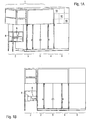
- Figur 1A -
- den Aufbau einer Anlage zur Sterilisation von Objekten mittels einer Strahlungsquelle, mit anschliessender Weiterbehandlungszone, in Perspektivansicht;
- Figur 1B -
- den Aufbau gemäss
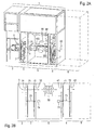
Figur 1A , in Frontansicht; - Figur 2A -
- den Aufbau gemäss
Figur 1A , mit teilweiser Einsicht in das Innere der Anlage; - Figur 2B -
- den Aufbau gemäss
Figur 1A , als Prinzipdarstellung; - Figur 3A -
- den Aufbau gemäss
Figur 1A , ohne Einbauten in der Bestrahlungszone und ohne Weiterbehandlungszone, in Perspektivansicht; - Figur 3B -
- den Aufbau gemäss
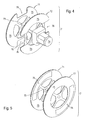
Figur 3A , in gewechselter Perspektive; - Figur 4 -
- eine Abschirmung aus
Figur 2A , in einer ersten Ausführung, in Perspektivansicht; - Figur 5 -
- eine Abschirmung in einer zvireiterAusführung, in Perspektivansicht;
- Figur 6A -
- die Abschirmung gemäss
Figur 4 , mit einem Abschnitt einer Transportstrecke und Gestell, in Perspektivansicht; - Figur 6B -
- den Aufbau gemäss
Figur 6A , in gewechselter Perspektive; - Figur 7A -
- den Aufbau gemäss
Figur 6A , mit einem angenäherten zu behandelnden Objekt, in Perspektivansicht; - Figur 7B -
- den Aufbau gemäss
Figur 7A , mit einem in die Abschirmung auf die Transportstrecke gebrachten Objekt, in Perspektivansicht; - Figur 7C -
- den Aufbau gemäss
Figur 7A , mit einem die Abschirmung über die Transportstrecke verlassenden Objekt, in Perspektivansicht; - Figur 8 -
- eine Abschirmung in einer dritten Ausführung, in Perspektivansicht;
- Figur 9A -
- eine charakteristische Stellungssituation der Abschirmungen und zu behandelnden Objekte innerhalb der Anlage, als Prinzipdarstellung;
- Figur 9B -
- eine weitere charakteristische Stellungssituation der Abschirmungen und zu behandelnden Objekte innerhalb der Anlage, als Prinzipdarstellung;
- Figur 10 -
- zwei aneinander gefügte Sandwichelemente mit zwischen gelegter Dichtung, als Prinzipdarstellung; und
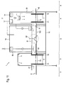
- Figur 11 -
- die apparative Ausstattung der Anlage und darin stattfindender Strömungsverlauf als Prinzipdarstellung.
- Anhand der beiliegenden Zeichnungen erfolgt nachstehend die detaillierte Beschreibung eines Ausführungsbeispiels der Anlage zur Sterilisation von Objekten mittels einer Strahlungsquelle. Zur in der Anlage eingesetzten Abschirmung werden alternative Lösungen dargestellt und ferner - über die essentiellen Merkmale hinaus - vorteilhafte konstruktive Einzelheiten offenbart.
- Für die gesamte weitere Beschreibung gilt folgende Festlegung. Sind in einer Figur zum Zweck zeichnerischer Eindeutigkeit Bezugsziffern enthalten, aber im unmittelbar zugehörigen Beschreibungstext nicht erläutert, so wird auf deren Erwähnung in vorangehenden Figurenbeschreibungen Bezug genommen. Im Interesse der Übersichtlichkeit wird auf die wiederholte Bezeichnung von Bauteilen in nachfolgenden Figuren zumeist verzichtet, sofern zeichnerisch eindeutig erkennbar ist, dass es sich um "wiederkehrende" Bauteile handelt.
- Das Zentrum der Anlage 1 bildet eine Bestrahlungszone 5, der eine Eingangszone 3 vorgesetzt und eine Ausgangszone 4 nachgeordnet ist. Vor der Eingangszone 3 befindet sich eine Beschickungszone 2, in welcher die Transportstrecke 6 zum Befördern der in der Anlage 1 zu behandelnden Objekte 8 beginnt. Hier wird die Anlage 1 mit den Objekten 8 beschickt und am Ende der Ausgangszone 4 werden die behandelten Objekte 8 ausgegeben, um in der Weiterbehandlungszone 9 dem fortgesetzten Arbeitsprozess unterzogen zu werden. An die Ausgangszone 4 schliesst sich eine Weiterbehandlungszone 9 an, typisch als Isolator oder Reinraum beschaffen, in welchem Personen tätig sein können. Solche Objekte 8 sind z.B. Behältnisse mit einer Vielzahl von zunächst leeren Injektionsspritzen, wobei die Behältnisse in der Anlage äusserlich zu sterilisieren sind und in der Weiterbehandlungszone 9 befüllt werden.
- Das Gehäuse der Anlage 1 ist vorteilhaft aus einer Vielzahl von Sandwichelementen 10 zusammengesetzt. Ein Sandwichelement 10 hat innen eine dickere strahlungsabsorbierende Schicht 100 - üblich aus Blei -, die zwischen zwei Aussenschichten 101 liegt, welche z.B. aus Edelstahlblech bestehen. Zwischen aneinander grenzende Sandwichelemente 10 sind Dichtungen 102 eingesetzt.
- Die Transportstrecke 6 beginnt in der Beschickungszone 2 und erstreckt sich fluchtend durch die gesamte Anlage 1, also die Eingangszone 3, die Bestrahlungszone 5 und die Ausgangszone 4. Innerhalb der Bestrahlungszone 5 ist die Transportstrecke 6 von dem Kanal 103 umgeben, um welchen die Strahlungsquelle 50, vorzugsweise in Gestalt eines Elektronenstrahlers, angeordnet ist. Die Strahlungsquelle 50 wirkt auf die den Kanal 103 auf der Transportstrecke 6 durchfahrende Objekte 8. In der Eingangszone 3 und in der Ausgangszone 4 ist jeweils eine Abschirmung 7 eingebaut.
- Die Eingangszone 3 hat eine erste Eingangsöffnung 31 mit Durchlass zur Beschickungszone 2 und eine zweite Eingangsöffnung 32 mit Durchlass zur Bestrahlungszone 5. Die Ausgangszone 4 hat eine erste Ausgangsöffnung 41 mit Durchlass zur Bestrahlungszone 5 und eine zweite Ausgangsöffnung 42 mit Durchlass zur Weiterbehandlungszone 9. Die Transportstrecke 6 erstreckt sich fluchtend durch die vier Öffnungen 31,32;41,42. In einer ersten Ausführungsform hat die Abschirmung 7 zwei scheibenförmige, drehbare Elemente 71,72, zwischen denen eine Verbindung 73, ähnlich einer Achse, besteht. Auf die Abschirmung 7 wirkt ein Antrieb 74. Die Elemente 71,72 erstrecken sich soweit über die vier Öffnungen 31,32;41,42 hinaus, dass in bestimmten Stellungssituationen diese Öffnungen 31,32;41,42 überdeckt werden. In der gezeigten Ausführung sind beide Elemente 71,72 innerhalb der Eingangszone 3 bzw. der Ausgangszone 4 positioniert. Alternativ könnte das erste Element 71 in der Beschickungszone 2 an der ersten Eingangsöffnung 31 und/oder das zweite Element 72 in der Bestrahlungszone 5 an der zweiten Eingangsöffnung 32 platziert sein.
- Die Abschirmung 7 hat zwei im Prinzip deckungsgleich parallel zueinander beabstandete, scheibenförmige Elemente 71,72, zwischen denen eine axiale Verbindung 73 besteht. Jedes Element 71,72 hat an seinem Umfang zwei Aussparungen 76, die radial offen und zueinander um 180° versetzt sind. Im übrigen Kreisring liegen Materialbereiche 75, während zum Zentrum hin grossflächige Durchbrüche der Gewichtsersparnis dienen. Entsprechend der Funktion der Abschirmung 7 als Schutz gegen den von der Strahlungsquelle 50 emittierten Elektronenstrom, besitzen die Elemente 71,72 einen strahlungsabsorbierenden Aufbau mit einer Schicht aus Blei. Die Aussparungen 76 des ersten Elements 71 sind gegenüber den Aussparungen 76 des zweiten Elements 72 so weit versetzt, dass keine Überlappung auftritt. In der Spannweite müssen die Aussparungen 76 die Passage der Objekte 8 erlauben und der lichte Abstand zwischen den Elementen 71,72 muss so bemessen sein, um darin einen Abschnitt der Transportstrecke 6 und in letzterer ein Objekt 8 aufnehmen zu können. Zur Stützung der in die Anlage 1 eingebauten Abschirmung 7 dient ein Gestell 79. Der mit der Abschirmung 7 gekoppelte Antrieb 74 ist vorzugsweise ein Elektromotor. Diese Ausführungsform der Abschirmung 7 ist für ein taktweises Weiterdrehen vorgesehen.
- Bei einer Stellung der Abschirmung 7, in welcher eine Aussparung 76 an der Passage der Transportstrecke 6 zu liegen kommt, lässt sich ein Objekt 8 zwischen die Elemente 71,72 einbringen oder andererseits entladen. Das Einbringen geschieht durch die erste Eingangöffnung 31 oder die erste Ausgangsöffnung 41. Das Entladen erfolgt durch die zweite Ausgangöffnung 32 oder die zweite Ausgangsöffnung 42. Steht hingegen ein Materialbereich 75 vor der Passage der Transportstrecke 6 - d.h. in der Anlage 1 vor einer der Öffnungen 31,32;41,42 - ist das Einbringen bzw. Entladen eines Objektes 8 blockiert, um den Strahlungsdurchlass zu verhindern.
- Je nach Konzeption des Bearbeitungsdurchlaufs der zu behandelnden Objekte 8 durch die Anlage 1 wird man die Verstellung zwischen der in der Eingangszone 3 eingebauten Abschirmung 7 und der in der Ausgangszone 4 positionierten Abschirmung 7 koordinieren.
- In der Stellungssituation gemäss
Figur 9A sind: - der Durchlass zwischen der Beschickungszone 2 und der Eingangszone 3 über die erste Eingangsöffnung 31 aufgrund des anstehenden Materialbereichs 75 gesperrt; ein Objekt 8 befindet sich vor der Eingangszone 3;
- der Durchlass zwischen der Eingangszone 3 und der Bestrahlungszone 5 über die zweite Eingangsöffnung 32 aufgrund der anstehenden Aussparung 76 offen; ein Objekt 8 hat die Eingangszone 3 verlassen und durchfährt die Bestrahlungszone 5;
- der Durchlass zwischen der Bestrahlungszone 5 und der Ausgangszone 4 über die erste Ausgangsöffnung 41 aufgrund der anstehenden Aussparung 76 offen; das Objekt 8 hat freie Einfahrt in die Ausgangszone 4; und
- der Durchlass zwischen der Ausgangszone 4 und der Weiterbehandlungszone 9 über die zweite Ausgangsöffnung 42 aufgrund des anstehenden Materialbereichs 75 gesperrt.
- Somit ist gesichert, dass in jeder Stellungssituation bei der vorteilhaft fluchtenden Transportstrecke 6, mit den entsprechend angeordneten Öffnungen 31,32;41,42, der Weg für die von der Strahlungsquelle 5 emittierte Strahlung in keiner Richtung entlang der Transportstrecke 6 niemals nach aussen frei ist. Eine Gefährdung von nahe der Anlage 1 sich aufhaltenden Personen ist damit ausgeschlossen.
- In der veränderten Stellungssituation gemäss
Figur 9B sind: - der Durchlass zwischen der Beschickungszone 2 und der Eingangszone 3 über die erste Eingangsöffnung 31 aufgrund der anstehenden Aussparung 76 offen; ein Objekt 8 ist von der Beschickungszone 2 in die Eingangszone 3 gefahren;
- der Durchlass zwischen der der Eingangszone 3 und der Bestrahlungszone 5 über die zweite Eingangsöffnung 32 aufgrund des anstehenden Materialbereichs 75 gesperrt; das Objekt 8 kann die Eingangszone 3 nicht verlassen;
- der Durchlass zwischen der Bestrahlungszone 5 und der Ausgangszone 4 über die erste Ausgangsöffnung 41 aufgrund des anstehenden Materialbereichs 75 gesperrt; und
- der Durchlass zwischen der Ausgangszone 4 und der Weiterbehandlungszone 9 über die zweite Ausgangsöffnung 42 aufgrund der anstehenden Aussparung 76 offen; das Objekt 8 kann die Ausgangszone 4 hin zur Weiterbehandlungszone 9 verlassen.
- Auch hier ist gesichert, dass die emittierte Strahlung in keiner Richtung entlang der Transportstrecke 6 nach aussen austreten kann.
- Für ein kontinuierliches Rotieren der Abschirmung 7, was die Nachteile des Stop and Go-Betriebs vermeidet, hat bei dieser alternativen Ausführungsform jedes Element 71,72 nur eine Aussparung 76, welche im Kreisbogen ein Vielfaches der Grösse eines Objekts 8 beträgt und damit dessen Passage beim kontinuierlichen Bewegen der Abschirmung 7 erlaubt. Die Aussparungen 76 beider Elemente 71,72 sind nicht überlappend dimensioniert.
- Einen deutlich unterschiedlichen Aufbau hat die hiesige Ausführungsform der Abschirmung 7, welche aus zwei plattenförmigen verschieblichen oder verschwenkbaren Elementen 71,72 besteht, zwischen denen sich eine Verbindung 73 zur koordinierten Bewegung beider Elemente 71,72 erstreckt. Auch diese Abschirmung 7 ist mit einem Antrieb 74 verbunden, jedoch dehnt sich der Materialbereich 75 über jedes Element 71,72 aus, ohne dass daran Aussparungen 76 vorhanden sind.
- Die Strahlungsquelle 50 wirkt in einen Kanal 103 hinein, in welchem die Transportstrecke 6 zum Befördern der Objekte 8 verläuft, und der sich einerseits zur zweiten Eingangsöffnung 32 der Eingangszone 3 und andererseits zur ersten Ausgangsöffnung 41 der Ausgangszone 4 erstreckt. Zur Erzielung einer qualifizierten Reinheitsklasse von der Strahlungsquelle 50 bis über die gesamte Ausgangszone 4 wird letztere mit unidirektionaler Luftströmung betrieben.
- Zur Vermeidung, insbesondere von z.B. Ozon, das bei eingeschalteter Strahlungsquelle 50 durch Reaktion mit der betroffenen Luft entsteht, ist der von der Strahlungsquelle 50 beaufschlagte Behandlungsraum innerhalb des Kanals 103 mit einem Inertgas 51 gefüllt.
Claims (4)
- Anlage (1) zur Sterilisation von Objekten (8) mittels einer Strahlungsquelle (50), mit:a) einer Bestrahlungszone (5), in der die Strahlungsquelle (50) angeordnet ist;b) einer Eingangszone (3), die der Bestrahlungszone (5) vorgesetzt ist;c) einer Beschickungszone (2), die der Eingangszone (3) vorgesetzt ist;d) einer Ausgangszone (4), die sich an die Bestrahlungszone (5) anschliesst und der eine Weiterbehandlungszone (9) folgt;e) einer Transportstrecke (6), die durch die Anlage (1) verläuft und zum Befördern der Objekte (8) dient;f) einer Abschirmung (7), die der Eingangszone (3) zugeordnet ist; undg) einer Abschirmung (7), die der Ausgangszone (4) zugeordnet ist, dadurch gekennzeichnet, dassh) die Eingangszone (3) eine erste Eingangsöffnung (31) mit Durchlass zur Beschickungszone (2) und eine zweite Eingangsöffnung (32) mit Durchlass zur Bestrahlungszone (5) hat;i) die Ausgangszone (4) eine erste Ausgangsöffnung (41) mit Durchlass zur Bestrahlungszone (5) und eine zweite Ausgangsöffnung (42) mit Durchlass zur Weiterbehandlungszone (9) hat;j) die Transportstrecke (6) sich fluchtend durch die erste Eingangsöffnung (31), die zweite Eingangsöffnung (32), die erste Ausgangsöffnung (41) und die zweite Ausgangsöffnung (42) erstreckt;k) die Abschirmungen (7) beweglich sind und in jeder Stellungssituation der Abschirmungen (7), in welcher eine der beiden Eingangsöffnungen (31,32) oder eine der beiden Ausgangsöffnungen (41,42) die Passage der durch die Anlage (1) beförderten Objekte (8) erlaubt, die andere Eingangsöffnung (32,31) sowie die andere Ausgangsöffnung (42,41) von der jeweils zugeordneten Abschirmung (7) überdeckt ist;l) eine Abschirmung (7) aus zwei plattenförmigen, verschieblichen oder verschwenkbaren Elementen (71,72) besteht, zwischen denen sich eine Verbindung (73) erstreckt;m) die Elemente (71,72) Materialbereiche (75) haben;n) die Elemente. (71,72) in einem Abstand angeordnet sind, welcher die dazwischen liegende Aufnahme eines Objektes (8) erlaubt; undo) die Abschirmung (7) mit einem Antrieb (74) verbunden ist.
- Anlage (1) nach Anspruch 1, dadurch gekennzeichnet, dass
die Strahlungsquelle (50) in einen Kanal (103) hineinwirkt, in welchem die Transportstrecke (6) zum Befördern der Objekte (8) verläuft, und der sich einerseits zur zweiten Eingangsöffnung (32) der Eingangszone (3) und andererseits zur ersten Ausgangsöffnung (41) der Ausgangszone (4) erstreckt. - Anlage (1) nach Anspruch 1 oder 2, dadurch gekennzeichnet, dassa) das Gehäuse der Sterilisationsanlage (1) aus aneinandergefügten, gegenseitig abgedichteten Sandwichelementen (10) aufgebaut ist;b) ein Sandwichelement (10) zwischen zwei Aussenschichten (101), vorzugsweise Edelstahlblech, eine strahlungsabsorbierende innere Schicht (100), vorzugsweise aus Blei, besitzt; undc) zwischen benachbart angeordneten Sandwichelementen (10) eine Dichtung (102) vorgesehen ist.
- Anlage (1) nach einem der Ansprüche 1 bis 3, dadurch gekennzeichnet, dass der von der Strahlungsquelle (50) beaufschlagte Behandlungsraum eine Füllung von Inertgas enthält.
Applications Claiming Priority (2)
| Application Number | Priority Date | Filing Date | Title |
|---|---|---|---|
| US85756906P | 2006-11-08 | 2006-11-08 | |
| PCT/CH2007/000550 WO2008055375A1 (de) | 2006-11-08 | 2007-11-08 | Anlage zur sterilisation von objekten mittels strahlungsquelle |
Publications (2)
| Publication Number | Publication Date |
|---|---|
| EP2094313A1 EP2094313A1 (de) | 2009-09-02 |
| EP2094313B1 true EP2094313B1 (de) | 2012-05-23 |
Family
ID=38819607
Family Applications (1)
| Application Number | Title | Priority Date | Filing Date |
|---|---|---|---|
| EP07816233A Active EP2094313B1 (de) | 2006-11-08 | 2007-11-08 | Anlage zur sterilisation von objekten mittels strahlungsquelle |
Country Status (4)
| Country | Link |
|---|---|
| US (1) | US8513623B2 (de) |
| EP (1) | EP2094313B1 (de) |
| DK (1) | DK2094313T3 (de) |
| WO (1) | WO2008055375A1 (de) |
Cited By (2)
| Publication number | Priority date | Publication date | Assignee | Title |
|---|---|---|---|---|
| EP4424330A1 (de) | 2023-03-02 | 2024-09-04 | SKAN Stein AG | Verfahren zum seriellen transfer von gebinden durch eine prozesskammer zur weiterverarbeitung in einem containment unter aseptischen bedingungen und produktionsanlage dazu |
| EP4663209A1 (de) | 2024-06-10 | 2025-12-17 | SKAN Stein AG | Verfahren zum seriellen transfer von objekten durch eine prozesskammer zur weiterverarbeitung in einem containment unter aseptischen bedingungen und produktionsanlage dazu |
Families Citing this family (8)
| Publication number | Priority date | Publication date | Assignee | Title |
|---|---|---|---|---|
| FR2988612B1 (fr) * | 2012-04-02 | 2014-08-08 | Getinge La Calhene | Systeme de sterilisation par bombardement d'electrons a encombrement reduit |
| RU2589025C2 (ru) * | 2012-06-26 | 2016-07-10 | Эммануил Абрамович Мирочник | Блок радиационной обработки с модулями входа и выхода |
| JP6543092B2 (ja) * | 2015-05-27 | 2019-07-10 | 株式会社エアレックス | 電子線照射装置 |
| DE102015011435A1 (de) * | 2015-09-07 | 2017-03-23 | Maschinenbau U. Konstruktion Gmbh Elmshorn | Vorrichtung zur zerstörungsfreien Materialprüfung von Gegenständen ,insbesondere von Felgen und Rädern aus Leichtmetallguss |
| JP6780309B2 (ja) * | 2016-06-10 | 2020-11-04 | オムロン株式会社 | 検査装置 |
| EP3479848B1 (de) * | 2017-11-07 | 2022-10-05 | Metall + Plastic GmbH | Oberflächen-dekontaminationsvorrichtung sowie betriebsverfahren |
| DE102023116964A1 (de) * | 2023-06-27 | 2025-01-02 | Krones Aktiengesellschaft | Vorrichtung und Verfahren zum Behandeln und insbesondere Sterilisieren von Behältnissen |
| CN119418978B (zh) * | 2024-11-19 | 2025-10-28 | 中国科学院上海应用物理研究所 | 辐照舱的延长装置及辐照系统 |
Family Cites Families (11)
| Publication number | Priority date | Publication date | Assignee | Title |
|---|---|---|---|---|
| DE1073388B (de) | 1960-01-14 | Deutsche Gold- und Silber-Scheideanstalt vormals Roessler, Frankfurt/M | Vorrichtung zum kontinuierlichen Ein- und Austragen von rieselfähigen Feststoffen | |
| DE3321195A1 (de) | 1983-06-11 | 1984-12-13 | Bayer Ag, 5090 Leverkusen | Vorrichtung zur trockenhitzesterilisation von glasbehaeltnissen fuer parenterale arzneimittel |
| SE8801373D0 (sv) | 1988-04-14 | 1988-04-14 | Akerlund & Rausing Ab | Forfarande for sterilisering av forpackningsmaterial, forpackningsbehallare eller delar till sadana samt anordning for genomforande av forfarandet |
| DE4217054A1 (de) * | 1992-05-22 | 1993-11-25 | Bausch & Stroebel Maschf | Sterilisiertunnel |
| US5457269A (en) * | 1992-09-08 | 1995-10-10 | Zapit Technology, Inc. | Oxidizing enhancement electron beam process and apparatus for contaminant treatment |
| US5740221A (en) * | 1996-10-29 | 1998-04-14 | Morton International, Inc. | Airbag inflator x-ray inspection apparatus with rotating entry and exit doors |
| US6291003B1 (en) * | 1998-10-30 | 2001-09-18 | Excel Corporation | Method and apparatus for steam pasteurization of meat |
| US6713741B2 (en) * | 2000-04-28 | 2004-03-30 | Maytag Corporation | Conveyorized oven with automated door |
| FR2881351B1 (fr) | 2005-02-01 | 2009-01-16 | Linac Technologies Sas Soc Par | Installation et procede pour la sterilisation d'objets par bombardement d'electrons a faible energie |
| FR2884426B1 (fr) | 2005-04-19 | 2009-11-06 | Linac Technologies Sas Soc Par | Installation pour la sterilisation d'objets par bombardement d'electrons. |
| US7753977B2 (en) * | 2005-06-09 | 2010-07-13 | Filtration Group, Inc. | Air filtration system having a removable diffuser |
-
2007
- 2007-11-08 US US12/514,166 patent/US8513623B2/en active Active
- 2007-11-08 WO PCT/CH2007/000550 patent/WO2008055375A1/de not_active Ceased
- 2007-11-08 EP EP07816233A patent/EP2094313B1/de active Active
- 2007-11-08 DK DK07816233.6T patent/DK2094313T3/da active
Cited By (4)
| Publication number | Priority date | Publication date | Assignee | Title |
|---|---|---|---|---|
| EP4424330A1 (de) | 2023-03-02 | 2024-09-04 | SKAN Stein AG | Verfahren zum seriellen transfer von gebinden durch eine prozesskammer zur weiterverarbeitung in einem containment unter aseptischen bedingungen und produktionsanlage dazu |
| WO2024178515A2 (de) | 2023-03-02 | 2024-09-06 | SKAN Stein AG | Verfahren zum seriellen transfer von gebinden durch eine prozesskammer zur weiterverarbeitung in einem containment unter aseptischen bedingungen und produktionsanlage dazu |
| EP4663209A1 (de) | 2024-06-10 | 2025-12-17 | SKAN Stein AG | Verfahren zum seriellen transfer von objekten durch eine prozesskammer zur weiterverarbeitung in einem containment unter aseptischen bedingungen und produktionsanlage dazu |
| WO2025255688A1 (de) | 2024-06-10 | 2025-12-18 | SKAN Stein AG | Verfahren zum seriellen transfer von objekten durch eine prozesskammer zur weiterverarbeitung in einem containment unter aseptischen bedingungen und produktionsanlage dazu |
Also Published As
| Publication number | Publication date |
|---|---|
| US20120168642A1 (en) | 2012-07-05 |
| DK2094313T3 (da) | 2012-08-20 |
| WO2008055375A1 (de) | 2008-05-15 |
| US8513623B2 (en) | 2013-08-20 |
| EP2094313A1 (de) | 2009-09-02 |
Similar Documents
| Publication | Publication Date | Title |
|---|---|---|
| WO2008055375A1 (de) | Anlage zur sterilisation von objekten mittels strahlungsquelle | |
| EP2845609B1 (de) | Vorrichtung und Verfahren zum Sterilisieren von Behältnissen mit Wartungsmöglichkeit | |
| EP2854497B1 (de) | Verfahren und vorrichtung zur desinfektion rieselfähiger produkte, vorzugsweise saatgut, mit beschleunigten elektronen | |
| EP2650022B1 (de) | Vorrichtung und Verfahren zum strahlungsbasierten Sterilisieren von Behältnisverschlüssen | |
| EP2845610B1 (de) | Vorrichtung zur Strahlenabschirmung beim Sterilisieren von Behältnissen | |
| EP2594493B1 (de) | Vorrichtung zur Innen- und Außensterilisierung von Vorformlingen mittels Ladungsträgerstrahlen sowie entsprechendes Verfahren und Behandlungsanlage | |
| EP3044156B1 (de) | Drehdurchführung sowie vorrichtung zur behandlung und/oder zum transport von behältern mit einer solchen drehdurchführung | |
| EP2371397A1 (de) | Vorrichtung zum Sterilisieren von Behältnissen | |
| EP3479848B1 (de) | Oberflächen-dekontaminationsvorrichtung sowie betriebsverfahren | |
| EP2293820A1 (de) | Vorrichtung zum sterilisieren von behältnissen mittels ladungsträgern | |
| WO2019034424A1 (de) | Dekontaminationsvorrichtung, isolatorsystem sowie betriebsverfahren | |
| EP0705531A2 (de) | Einrichtung zur Elektronenbehandlung von Schüttgut, vorzugsweise von Saatgut | |
| EP3429639A1 (de) | ANORDNUNG ZUM DESINFIZIEREN VON DOSENDECKELN ZUM VERSCHLIEßEN VON DOSEN | |
| EP2687236B1 (de) | Verfahren und Vorrichtung zum Sterilisieren von Behältnissen mit Kühlluftentnahme aus dem Sterilraum | |
| DE202010017347U1 (de) | Filtervorrichtung für eine von einem gasstrom durchflossene anlage mit einer arbeitskammer zur temporären aufnahme von behandlungsgut | |
| EP1051197A2 (de) | Verfahren zum bestrahlen eines gutes mit elektronenbestrahlung | |
| EP2719399A1 (de) | Behältnissterilisation mittels Elektronenstrahlen mit Strahlschutz für Strahlfinger | |
| EP3444193A1 (de) | Dekontaminationsvorrichtung, isolatorsystem sowie betriebsverfahren | |
| DE102013103259A1 (de) | Desinfektionsmodul für eine Serienprozessanlage | |
| CH697990B1 (de) | Anordnung zum sterilen Abfüllen. | |
| EP2282783B1 (de) | Vorrichtung zum sterilisieren von behältnisverschlüssen | |
| EP2803368B1 (de) | Vorrichtung und Verfahren zum Sterilisieren von Behältnissen mit Abschirmeinrichtung gegen Röntgenstrahlen | |
| DE202012103519U1 (de) | Vorrichtung zum Sterilisieren von Behältnissen mit Aufbereitung für Kühlmedium | |
| EP2529897A1 (de) | Anordnung zur automatischen Handhabung radioaktiver Stoffe | |
| EP4702993A1 (de) | Transfersystem mit wenigstens einer ersten transferschnittstelle einer ersten kontrollierten umgebung, verfahren zum koppeln wenigstens einer ersten transferschnittstelle einer kontrollierten umgebung mit wenigstens einer zweiten transferschnittstelle, verfahren zum transferieren eines gegenstands |
Legal Events
| Date | Code | Title | Description |
|---|---|---|---|
| PUAI | Public reference made under article 153(3) epc to a published international application that has entered the european phase |
Free format text: ORIGINAL CODE: 0009012 |
|
| 17P | Request for examination filed |
Effective date: 20090508 |
|
| AK | Designated contracting states |
Kind code of ref document: A1 Designated state(s): AT BE BG CH CY CZ DE DK EE ES FI FR GB GR HU IE IS IT LI LT LU LV MC MT NL PL PT RO SE SI SK TR |
|
| 17Q | First examination report despatched |
Effective date: 20090928 |
|
| DAX | Request for extension of the european patent (deleted) | ||
| GRAP | Despatch of communication of intention to grant a patent |
Free format text: ORIGINAL CODE: EPIDOSNIGR1 |
|
| RIC1 | Information provided on ipc code assigned before grant |
Ipc: A61L 2/08 20060101AFI20111215BHEP |
|
| GRAS | Grant fee paid |
Free format text: ORIGINAL CODE: EPIDOSNIGR3 |
|
| GRAA | (expected) grant |
Free format text: ORIGINAL CODE: 0009210 |
|
| RIN1 | Information on inventor provided before grant (corrected) |
Inventor name: SMITH, PAUL ALEXANDER Inventor name: NEWMAN, JOHN THOMAS Inventor name: SIGWARTH, VOLKER |
|
| AK | Designated contracting states |
Kind code of ref document: B1 Designated state(s): AT BE BG CH CY CZ DE DK EE ES FI FR GB GR HU IE IS IT LI LT LU LV MC MT NL PL PT RO SE SI SK TR |
|
| REG | Reference to a national code |
Ref country code: GB Ref legal event code: FG4D Free format text: NOT ENGLISH |
|
| REG | Reference to a national code |
Ref country code: CH Ref legal event code: NV Representative=s name: AXON PATENT GMBH Ref country code: CH Ref legal event code: EP |
|
| REG | Reference to a national code |
Ref country code: AT Ref legal event code: REF Ref document number: 558745 Country of ref document: AT Kind code of ref document: T Effective date: 20120615 |
|
| REG | Reference to a national code |
Ref country code: IE Ref legal event code: FG4D Free format text: LANGUAGE OF EP DOCUMENT: GERMAN |
|
| REG | Reference to a national code |
Ref country code: DE Ref legal event code: R096 Ref document number: 502007009922 Country of ref document: DE Effective date: 20120726 |
|
| REG | Reference to a national code |
Ref country code: SE Ref legal event code: TRGR |
|
| REG | Reference to a national code |
Ref country code: DK Ref legal event code: T3 |
|
| REG | Reference to a national code |
Ref country code: NL Ref legal event code: T3 |
|
| REG | Reference to a national code |
Ref country code: LT Ref legal event code: MG4D Effective date: 20120523 |
|
| PG25 | Lapsed in a contracting state [announced via postgrant information from national office to epo] |
Ref country code: IS Free format text: LAPSE BECAUSE OF FAILURE TO SUBMIT A TRANSLATION OF THE DESCRIPTION OR TO PAY THE FEE WITHIN THE PRESCRIBED TIME-LIMIT Effective date: 20120923 Ref country code: CY Free format text: LAPSE BECAUSE OF FAILURE TO SUBMIT A TRANSLATION OF THE DESCRIPTION OR TO PAY THE FEE WITHIN THE PRESCRIBED TIME-LIMIT Effective date: 20120523 Ref country code: FI Free format text: LAPSE BECAUSE OF FAILURE TO SUBMIT A TRANSLATION OF THE DESCRIPTION OR TO PAY THE FEE WITHIN THE PRESCRIBED TIME-LIMIT Effective date: 20120523 Ref country code: LT Free format text: LAPSE BECAUSE OF FAILURE TO SUBMIT A TRANSLATION OF THE DESCRIPTION OR TO PAY THE FEE WITHIN THE PRESCRIBED TIME-LIMIT Effective date: 20120523 |
|
| PG25 | Lapsed in a contracting state [announced via postgrant information from national office to epo] |
Ref country code: GR Free format text: LAPSE BECAUSE OF FAILURE TO SUBMIT A TRANSLATION OF THE DESCRIPTION OR TO PAY THE FEE WITHIN THE PRESCRIBED TIME-LIMIT Effective date: 20120824 Ref country code: SI Free format text: LAPSE BECAUSE OF FAILURE TO SUBMIT A TRANSLATION OF THE DESCRIPTION OR TO PAY THE FEE WITHIN THE PRESCRIBED TIME-LIMIT Effective date: 20120523 Ref country code: LV Free format text: LAPSE BECAUSE OF FAILURE TO SUBMIT A TRANSLATION OF THE DESCRIPTION OR TO PAY THE FEE WITHIN THE PRESCRIBED TIME-LIMIT Effective date: 20120523 Ref country code: PT Free format text: LAPSE BECAUSE OF FAILURE TO SUBMIT A TRANSLATION OF THE DESCRIPTION OR TO PAY THE FEE WITHIN THE PRESCRIBED TIME-LIMIT Effective date: 20120924 |
|
| PG25 | Lapsed in a contracting state [announced via postgrant information from national office to epo] |
Ref country code: EE Free format text: LAPSE BECAUSE OF FAILURE TO SUBMIT A TRANSLATION OF THE DESCRIPTION OR TO PAY THE FEE WITHIN THE PRESCRIBED TIME-LIMIT Effective date: 20120523 Ref country code: SK Free format text: LAPSE BECAUSE OF FAILURE TO SUBMIT A TRANSLATION OF THE DESCRIPTION OR TO PAY THE FEE WITHIN THE PRESCRIBED TIME-LIMIT Effective date: 20120523 Ref country code: CZ Free format text: LAPSE BECAUSE OF FAILURE TO SUBMIT A TRANSLATION OF THE DESCRIPTION OR TO PAY THE FEE WITHIN THE PRESCRIBED TIME-LIMIT Effective date: 20120523 Ref country code: RO Free format text: LAPSE BECAUSE OF FAILURE TO SUBMIT A TRANSLATION OF THE DESCRIPTION OR TO PAY THE FEE WITHIN THE PRESCRIBED TIME-LIMIT Effective date: 20120523 |
|
| PG25 | Lapsed in a contracting state [announced via postgrant information from national office to epo] |
Ref country code: PL Free format text: LAPSE BECAUSE OF FAILURE TO SUBMIT A TRANSLATION OF THE DESCRIPTION OR TO PAY THE FEE WITHIN THE PRESCRIBED TIME-LIMIT Effective date: 20120523 |
|
| PLBE | No opposition filed within time limit |
Free format text: ORIGINAL CODE: 0009261 |
|
| STAA | Information on the status of an ep patent application or granted ep patent |
Free format text: STATUS: NO OPPOSITION FILED WITHIN TIME LIMIT |
|
| PG25 | Lapsed in a contracting state [announced via postgrant information from national office to epo] |
Ref country code: ES Free format text: LAPSE BECAUSE OF FAILURE TO SUBMIT A TRANSLATION OF THE DESCRIPTION OR TO PAY THE FEE WITHIN THE PRESCRIBED TIME-LIMIT Effective date: 20120903 |
|
| 26N | No opposition filed |
Effective date: 20130226 |
|
| REG | Reference to a national code |
Ref country code: DE Ref legal event code: R097 Ref document number: 502007009922 Country of ref document: DE Effective date: 20130226 |
|
| PG25 | Lapsed in a contracting state [announced via postgrant information from national office to epo] |
Ref country code: BG Free format text: LAPSE BECAUSE OF FAILURE TO SUBMIT A TRANSLATION OF THE DESCRIPTION OR TO PAY THE FEE WITHIN THE PRESCRIBED TIME-LIMIT Effective date: 20120823 |
|
| PG25 | Lapsed in a contracting state [announced via postgrant information from national office to epo] |
Ref country code: MT Free format text: LAPSE BECAUSE OF FAILURE TO SUBMIT A TRANSLATION OF THE DESCRIPTION OR TO PAY THE FEE WITHIN THE PRESCRIBED TIME-LIMIT Effective date: 20120523 |
|
| REG | Reference to a national code |
Ref country code: AT Ref legal event code: MM01 Ref document number: 558745 Country of ref document: AT Kind code of ref document: T Effective date: 20121130 |
|
| PG25 | Lapsed in a contracting state [announced via postgrant information from national office to epo] |
Ref country code: AT Free format text: LAPSE BECAUSE OF NON-PAYMENT OF DUE FEES Effective date: 20121130 |
|
| PG25 | Lapsed in a contracting state [announced via postgrant information from national office to epo] |
Ref country code: MC Free format text: LAPSE BECAUSE OF NON-PAYMENT OF DUE FEES Effective date: 20121130 Ref country code: TR Free format text: LAPSE BECAUSE OF FAILURE TO SUBMIT A TRANSLATION OF THE DESCRIPTION OR TO PAY THE FEE WITHIN THE PRESCRIBED TIME-LIMIT Effective date: 20120523 |
|
| PG25 | Lapsed in a contracting state [announced via postgrant information from national office to epo] |
Ref country code: LU Free format text: LAPSE BECAUSE OF NON-PAYMENT OF DUE FEES Effective date: 20121108 |
|
| PG25 | Lapsed in a contracting state [announced via postgrant information from national office to epo] |
Ref country code: HU Free format text: LAPSE BECAUSE OF FAILURE TO SUBMIT A TRANSLATION OF THE DESCRIPTION OR TO PAY THE FEE WITHIN THE PRESCRIBED TIME-LIMIT Effective date: 20071108 |
|
| REG | Reference to a national code |
Ref country code: FR Ref legal event code: PLFP Year of fee payment: 9 |
|
| REG | Reference to a national code |
Ref country code: FR Ref legal event code: PLFP Year of fee payment: 10 |
|
| REG | Reference to a national code |
Ref country code: FR Ref legal event code: PLFP Year of fee payment: 11 |
|
| REG | Reference to a national code |
Ref country code: DE Ref legal event code: R082 Ref document number: 502007009922 Country of ref document: DE Representative=s name: SCHIEBER - FARAGO PATENTANWAELTE, DE Ref country code: DE Ref legal event code: R082 Ref document number: 502007009922 Country of ref document: DE Representative=s name: FARAGO PATENTANWALTSGESELLSCHAFT MBH, DE Ref country code: DE Ref legal event code: R082 Ref document number: 502007009922 Country of ref document: DE Representative=s name: MAUCHER JENKINS PATENTANWAELTE & RECHTSANWAELT, DE |
|
| REG | Reference to a national code |
Ref country code: DE Ref legal event code: R082 Ref document number: 502007009922 Country of ref document: DE Representative=s name: SCHIEBER - FARAGO PATENTANWAELTE, DE Ref country code: DE Ref legal event code: R082 Ref document number: 502007009922 Country of ref document: DE Representative=s name: MAUCHER JENKINS PATENTANWAELTE & RECHTSANWAELT, DE |
|
| REG | Reference to a national code |
Ref country code: CH Ref legal event code: U11 Free format text: ST27 STATUS EVENT CODE: U-0-0-U10-U11 (AS PROVIDED BY THE NATIONAL OFFICE) Effective date: 20251201 |
|
| PGFP | Annual fee paid to national office [announced via postgrant information from national office to epo] |
Ref country code: NL Payment date: 20251119 Year of fee payment: 19 |
|
| REG | Reference to a national code |
Ref country code: CH Ref legal event code: R17 Free format text: ST27 STATUS EVENT CODE: U-0-0-R10-R17 (AS PROVIDED BY THE NATIONAL OFFICE) Effective date: 20260107 |
|
| PGFP | Annual fee paid to national office [announced via postgrant information from national office to epo] |
Ref country code: DE Payment date: 20251118 Year of fee payment: 19 |
|
| PGFP | Annual fee paid to national office [announced via postgrant information from national office to epo] |
Ref country code: GB Payment date: 20251120 Year of fee payment: 19 |
|
| PGFP | Annual fee paid to national office [announced via postgrant information from national office to epo] |
Ref country code: IT Payment date: 20251128 Year of fee payment: 19 Ref country code: DK Payment date: 20251119 Year of fee payment: 19 |
|
| PGFP | Annual fee paid to national office [announced via postgrant information from national office to epo] |
Ref country code: FR Payment date: 20251120 Year of fee payment: 19 |
|
| PGFP | Annual fee paid to national office [announced via postgrant information from national office to epo] |
Ref country code: BE Payment date: 20251118 Year of fee payment: 19 |
|
| PGFP | Annual fee paid to national office [announced via postgrant information from national office to epo] |
Ref country code: SE Payment date: 20251119 Year of fee payment: 19 Ref country code: CH Payment date: 20251201 Year of fee payment: 19 |
|
| PGFP | Annual fee paid to national office [announced via postgrant information from national office to epo] |
Ref country code: IE Payment date: 20251120 Year of fee payment: 19 |
|
| REG | Reference to a national code |
Ref country code: DE Ref legal event code: R082 Ref document number: 502007009922 Country of ref document: DE Representative=s name: MAUCHER JENKINS PATENTANWAELTE & RECHTSANWAELT, DE |