EP2094136B1 - Fryer fire suppression system - Google Patents
Fryer fire suppression system Download PDFInfo
- Publication number
- EP2094136B1 EP2094136B1 EP07869596A EP07869596A EP2094136B1 EP 2094136 B1 EP2094136 B1 EP 2094136B1 EP 07869596 A EP07869596 A EP 07869596A EP 07869596 A EP07869596 A EP 07869596A EP 2094136 B1 EP2094136 B1 EP 2094136B1
- Authority
- EP
- European Patent Office
- Prior art keywords
- fryer
- nozzle
- fire suppression
- lid
- suppression system
- Prior art date
- Legal status (The legal status is an assumption and is not a legal conclusion. Google has not performed a legal analysis and makes no representation as to the accuracy of the status listed.)
- Active
Links
Images




Classifications
-
- A—HUMAN NECESSITIES
- A47—FURNITURE; DOMESTIC ARTICLES OR APPLIANCES; COFFEE MILLS; SPICE MILLS; SUCTION CLEANERS IN GENERAL
- A47J—KITCHEN EQUIPMENT; COFFEE MILLS; SPICE MILLS; APPARATUS FOR MAKING BEVERAGES
- A47J37/00—Baking; Roasting; Grilling; Frying
- A47J37/12—Deep fat fryers, e.g. for frying fish or chips
-
- A—HUMAN NECESSITIES
- A47—FURNITURE; DOMESTIC ARTICLES OR APPLIANCES; COFFEE MILLS; SPICE MILLS; SUCTION CLEANERS IN GENERAL
- A47J—KITCHEN EQUIPMENT; COFFEE MILLS; SPICE MILLS; APPARATUS FOR MAKING BEVERAGES
- A47J37/00—Baking; Roasting; Grilling; Frying
- A47J37/12—Deep fat fryers, e.g. for frying fish or chips
- A47J37/1266—Control devices, e.g. to control temperature, level or quality of the frying liquid
-
- A—HUMAN NECESSITIES
- A47—FURNITURE; DOMESTIC ARTICLES OR APPLIANCES; COFFEE MILLS; SPICE MILLS; SUCTION CLEANERS IN GENERAL
- A47J—KITCHEN EQUIPMENT; COFFEE MILLS; SPICE MILLS; APPARATUS FOR MAKING BEVERAGES
- A47J27/00—Cooking-vessels
- A47J27/08—Pressure-cookers; Lids or locking devices specially adapted therefor
- A47J27/0817—Large-capacity pressure cookers; Pressure fryers
-
- A—HUMAN NECESSITIES
- A47—FURNITURE; DOMESTIC ARTICLES OR APPLIANCES; COFFEE MILLS; SPICE MILLS; SUCTION CLEANERS IN GENERAL
- A47J—KITCHEN EQUIPMENT; COFFEE MILLS; SPICE MILLS; APPARATUS FOR MAKING BEVERAGES
- A47J27/00—Cooking-vessels
- A47J27/08—Pressure-cookers; Lids or locking devices specially adapted therefor
- A47J27/09—Safety devices
-
- A—HUMAN NECESSITIES
- A47—FURNITURE; DOMESTIC ARTICLES OR APPLIANCES; COFFEE MILLS; SPICE MILLS; SUCTION CLEANERS IN GENERAL
- A47J—KITCHEN EQUIPMENT; COFFEE MILLS; SPICE MILLS; APPARATUS FOR MAKING BEVERAGES
- A47J37/00—Baking; Roasting; Grilling; Frying
- A47J37/12—Deep fat fryers, e.g. for frying fish or chips
- A47J37/1271—Accessories
-
- A—HUMAN NECESSITIES
- A47—FURNITURE; DOMESTIC ARTICLES OR APPLIANCES; COFFEE MILLS; SPICE MILLS; SUCTION CLEANERS IN GENERAL
- A47J—KITCHEN EQUIPMENT; COFFEE MILLS; SPICE MILLS; APPARATUS FOR MAKING BEVERAGES
- A47J37/00—Baking; Roasting; Grilling; Frying
- A47J37/12—Deep fat fryers, e.g. for frying fish or chips
- A47J37/1276—Constructional details
- A47J37/128—Integrated lids or covers
-
- A—HUMAN NECESSITIES
- A62—LIFE-SAVING; FIRE-FIGHTING
- A62C—FIRE-FIGHTING
- A62C3/00—Fire prevention, containment or extinguishing specially adapted for particular objects or places
- A62C3/006—Fire prevention, containment or extinguishing specially adapted for particular objects or places for kitchens or stoves
-
- A—HUMAN NECESSITIES
- A62—LIFE-SAVING; FIRE-FIGHTING
- A62C—FIRE-FIGHTING
- A62C3/00—Fire prevention, containment or extinguishing specially adapted for particular objects or places
- A62C3/06—Fire prevention, containment or extinguishing specially adapted for particular objects or places of highly inflammable material, e.g. light metals, petroleum products
- A62C3/065—Fire prevention, containment or extinguishing specially adapted for particular objects or places of highly inflammable material, e.g. light metals, petroleum products for containers filled with inflammable liquids
Definitions
- a pressure fryer is used to cook food (such as meat) in a vat using cooking oil.
- the food and cooking oil in the pressure fryer are brought to high temperatures while pressure is held high enough that the water within may be prevented from boiling off. This technique can leave the food very hot and juicy.
- the pressure fryer is typically used in industrial kitchens and can include a fire suppression system. Specifically, nozzles are positioned to direct fire suppression agent to the center of the vat when the lid of the pressure fryer is open. While this configuration reduces the possibility of fire in the pressure fryer, a better configuration is desired. US patent number 5,129,386 discloses such an improved configuration.
- the present embodiments relate to a fire suppression system for an appliance, such as a pressure fryer.
- the fryer may have a fry vat (in which the food and cooking oil are placed) and a lid for covering the fry vat.
- the lid of the fryer may have three positions, a fully open position, a closed/unlocked position (with lid being closed and the fry vat being vented through an opening) and a closed/locked position (with the fry vat sealed for cooking).
- the fire suppression system for the fryer includes a reservoir of fire suppression agent, piping connected to the reservoir, and one or more nozzles connected to the piping and configured to direct fire suppression agent into the fry vat when the lid is not in the fully open position (such as when the lid is in the closed/unlocked position).
- a headspace may be created between the fry vat and an interior portion of the lid.
- the nozzle when the lid is in the closed and unlocked position (creating an opening into the headspace for venting of the fry vat), the nozzle may be configured external to both the lid and the fry vat so that fire suppression agent is directed through the opening and into headspace of the fry vat.
- the nozzle may be a flat spray (such as fan pattern) so more fire suppression agent may be inserted into the slot-shaped opening.
- the nozzle may be configured to insert fire suppression agent into another opening into the fry vat when the lid is in the closed/unlocked position.
- the fry vat may include an opening to an overflow drain pipe that flows to an overflow drain.
- the nozzle may be configured such that fire suppression agent is inserted into the headspace of the flyer vat through the opening to the overflow drain pipe.
- the fire suppression system may include one or more nozzles connected to the piping and configured to direct fire suppression agent into the fry vat when the lid is in the fully open position.
- the one or more nozzles configured to direct fire suppression agent into the vat when the lid is in the fully open position may differ from the one or more nozzles configured to direct fire suppression agent into the fry vat when the lid is not in the fully open position in several respects, including: (1) position (such as position in the x-, y-, and/or z- direction); (2) type of nozzle (such as fan shaped versus cone shaped); and (3) aiming of nozzle (such as aiming upward or downward).
- the one or more nozzles configured to direct fire suppression agent into the fry vat when the lid is not in the fully open position to work either alone or in combination with the one or more nozzles configured to direct fire suppression agent into the vat when the lid is in the fully open position.
- the fire suppression system may better combat a fire in the pressure fryer.
- Figure 1 is a front view of a mono rail center lid-lift pressure fryer with an example of a fire suppression system.
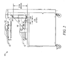
- Figure 2 is a side view of the mono rail center lid-lift pressure fryer depicted in Figure 1 .
- Figure 3 is a top view of the mono rail center lid-lift pressure fryer depicted in Figure 1 .
- Figures 4a and 4b are a top view and an end view, respectively, of the Tee block depicted in Figure 1 .
- Figure 5 is a front view of a dual lid-lift pressure fryer with an example of a fire suppression system.
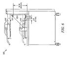
- Figure 6 is a side view of the dual lid-lift pressure fryer depicted in Figure 5 .
- Figure 7 is a top view of the dual lid-lift pressure fryer depicted in Figure 5 .
- the fire suppression system may be used in a variety of fryers, including pressure fryers.
- Two examples of pressure fryers are shown, including a mono rail center lid-lift fryer system (shown in Figures 1-3 ) and a dual lid-lift fryer system (shown in Figures 5-7 ).
- the listed models are for illustrative purposes only. Fryers from other manufacturers and other configurations may be used as well.
- the fire suppression system may provide protection from fires with the lid in the fully open position (such as the fully open lid position) and/or in a closed position.
- the lid in the fryer system may be in one of three positions including: (1) fully open position; (2) fully closed and locked; and (3) closed and vented.
- the fully open position may be when the loading rack and baskets of the fryer are in the fully open position.
- One example of an intermediate position (between the fully open position and the fully closed and locked position) may be when the lid is fully closed and the handle of the fryer is unlocked, creating an opening or a slot, thereby releasing the steam pressure from the headspace of the fryer vat. In this position, the safety latch may still be latched.
- a portion of the fryer may be open for venting of the fry vat.
- the back portion of the fryer may be open, such as 1 ⁇ 4 inch slot opening, to vent the vat of the fryer.
- fire suppression systems are configured only to suppress fires when the lid of the fryer is in the fully open position.
- the fryer may be at risk to fires when the lid of the fryer is not in the fully open position.
- the fryer may still be at risk of a fire (such as due to oil in the vat bubbling out of the opening or air entering the vat).
- Figures 1-7 may be used to reduce the risk of fire when the fryer is in the fully open position and/or is not in the fully open position.
- Figure 1 illustrates a front view of a mono rail center lid lift fryer system, with the lid 110 in the open position and the mono rail illustrated by element 130. The combination of the fryer and fryer fire suppression system is depicted as element 100.
- Figure 2 illustrates a side view of the fryer system depicted in Figure 1 , with the lid shown in the fully open position and in the venting position (in the venting position, the lid is shown in dashed lines).
- Figure 3 depicts a top view of the fryer system depicted in Figure 1 .
- FIG 1 depicts a "Tee block” 120 which may be mounted to the fryer.
- the Tee block 120 may be mounted to the fryer, such as a back portion of the fryer.
- the Tee block 120 is depicted in Figures 4a-b .
- Nozzles may be attached to the fryer using a nozzle assembly kit, which may comprise nozzles, nozzle swivel adaptors, nozzle caps, tee block with fasteners, close nipples, various stainless pipe lengths, and elbows.
- the nozzles may be configured in a variety of places in the Tee block in order to direct a fire suppression agent at different portions of the fryer.
- the fire suppression agent may be any substance that may be used to inhibit or reduce the effects of a fire.
- Figures 2 and 3 illustrate two nozzles 210, 220 used in the fire suppression system.
- the two nozzles 210, 220 depicted in Figures 2 and 3 are for illustrative purposes and fewer or greater number of nozzles may be used, as discussed in more detail below.
- At least two of the nozzles in the system may differ from one another in several ways including: position (such as position in the x-, y-, and/or z- direction); type of nozzle; and aiming of nozzle (such as aiming upward or downward).
- the two nozzles 210, 220 are in different positions (different in the z-direction) and have opposite aiming of the agent from the nozzles (upward versus downward).
- the IN Nozzle 210 from the Tee Block, Part No. 434424, may be configured so that nozzle tip is located 16 in. (40.6 cm) up from base of fryer surface and 5 in. (12.7 cm) in from right side of appliance back shroud.
- the IN Nozzle 210 may be aimed downward (and to one side, such as at an approximately 45° downward (shown in Figure 2 ) and a 45° inward (shown in Figure 3 )), to discharge at a center point of the fry vat.
- the IF Nozzle 220 running down from the Tee Block to the base of the fryer, may have its nozzle tip located 2 in. (5.1 cm) from the back side of the fry vat, and 8 in.
- the I F nozzle 220 may be aimed upward, as shown in Figure 2 .
- the fire suppression agent may be directed through the opening 240 of the back portion that is non-closed and under the cover of the lid 110. In this way, the fire suppression agent may be inserted into the headspace of the fryer vat 140.
- the opening 240 is shown in Figure 2 at the back portion, the opening 240 may be along one or more sides of the vat
- first nozzle 210 and second nozzle 220 may be of different types.
- first nozzle 210 may be a narrow pattern nozzle (such as cone shaped), for instance 1N, Part No. 419335.
- the second nozzle 220 may be a flat spray (such as fan pattern), for instance 1F, Part No. 419333.
- the I F nozzle 220 may be a flat spray nozzle and the spray may be horizontal to that of the edge of the back lip of the fry vat.
- Each fryer may include a reservoir (not shown) having a minimum of 3.0 Gallons of ANSULEX ® Low pH fire suppression agent. Piping may be used to connect the reservoir discharging through the two one-flow nozzles (IN and IF). An example of the piping is shown at element 230. The two nozzles 210, 220 may be operated simultaneously, such as emitting fire suppression agent at the same time.
- Figure 4a and 4b depict a top view and an end view (respectively) of a portion of the Tee block 120.
- the Tee block may be attached to the fryer via holes 410 for using screws, shown in Figure 4a . Additional holes may be used for inlets (to input the fire suppression agent via tubing into the Tee block 120, and for outlets for the nozzles. Piping may also be included in the Tee block 120, shown by the dashed lines in Figures 4a and 4b .
- Figure 4b illustrates a connection to 3/8" national pipe thread (NPT) tubing.
- NPT national pipe thread
- Figure 5 illustrates a front view of a dual lid lift fryer system, with the lid in the open position.
- the combination of the fryer and fryer fire suppression system is depicted as element 500 with Tee Block 510 and fryer vat 520.
- Figure 6 illustrates a side view of the fryer system depicted in Figure 5 , with the lid shown in the fully open position and the venting position.
- Figure 7 depicts a top view of the fryer system depicted in Figure 5 .
- the first nozzle 610 in Figures 6 and 7 may be a narrow pattern nozzle (such as cone shaped) positioned in an upper position, for instance IN, Part No. 419335.
- the second nozzle 620 may be a flat spray (such as fan pattern) positioned in a lower position, for instance 1F, Part No. 419333.
- the nozzles 610, 620 may be positioned on the fryer in different locations.
- the IN Nozzle 610 in the upper position, from the Tee Block 510, Part No. 434424, may be configured so that nozzle tip is located 16 in. (40.6 cm) up from base of fryer surface and 5 in. (12.7 cm) in from left side of appliance back shroud (as opposed to the right side as shown in Figure 3 ).
- the IN Nozzle 610 may be aimed downward to discharge at a center point of fry vat.
- the 1F Nozzle 620 in the lower position, running down from the Tee Block 510 via piping 630 to the base of the fryer may have its nozzle tip located 2 in. (5.1 cm) from back side of fry vat, and 8 in.
- the I F nozzle 620 may be a flat spray nozzle and the spray may be horizontal to that of the edge of the back lip of the fry vat.
- the I F nozzle 620 may be aimed upward, as shown in Figure 6 .
Landscapes
- Engineering & Computer Science (AREA)
- Food Science & Technology (AREA)
- Health & Medical Sciences (AREA)
- Public Health (AREA)
- Business, Economics & Management (AREA)
- Emergency Management (AREA)
- Frying-Pans Or Fryers (AREA)
- Fire-Extinguishing By Fire Departments, And Fire-Extinguishing Equipment And Control Thereof (AREA)
- Fire-Extinguishing Compositions (AREA)
Description
- A pressure fryer is used to cook food (such as meat) in a vat using cooking oil. The food and cooking oil in the pressure fryer are brought to high temperatures while pressure is held high enough that the water within may be prevented from boiling off. This technique can leave the food very hot and juicy. The pressure fryer is typically used in industrial kitchens and can include a fire suppression system. Specifically, nozzles are positioned to direct fire suppression agent to the center of the vat when the lid of the pressure fryer is open. While this configuration reduces the possibility of fire in the pressure fryer, a better configuration is desired.
US patent number 5,129,386 discloses such an improved configuration. - The present embodiments relate to a fire suppression system for an appliance, such as a pressure fryer. The fryer may have a fry vat (in which the food and cooking oil are placed) and a lid for covering the fry vat. The lid of the fryer may have three positions, a fully open position, a closed/unlocked position (with lid being closed and the fry vat being vented through an opening) and a closed/locked position (with the fry vat sealed for cooking). The fire suppression system for the fryer includes a reservoir of fire suppression agent, piping connected to the reservoir, and one or more nozzles connected to the piping and configured to direct fire suppression agent into the fry vat when the lid is not in the fully open position (such as when the lid is in the closed/unlocked position).
- For example, when the lid is closed, a headspace may be created between the fry vat and an interior portion of the lid. In one aspect of the invention, when the lid is in the closed and unlocked position (creating an opening into the headspace for venting of the fry vat), the nozzle may be configured external to both the lid and the fry vat so that fire suppression agent is directed through the opening and into headspace of the fry vat. The nozzle may be a flat spray (such as fan pattern) so more fire suppression agent may be inserted into the slot-shaped opening. As another example, the nozzle may be configured to insert fire suppression agent into another opening into the fry vat when the lid is in the closed/unlocked position. Specifically, the fry vat may include an opening to an overflow drain pipe that flows to an overflow drain. The nozzle may be configured such that fire suppression agent is inserted into the headspace of the flyer vat through the opening to the overflow drain pipe.
- Moreover, the fire suppression system may include one or more nozzles connected to the piping and configured to direct fire suppression agent into the fry vat when the lid is in the fully open position. The one or more nozzles configured to direct fire suppression agent into the vat when the lid is in the fully open position may differ from the one or more nozzles configured to direct fire suppression agent into the fry vat when the lid is not in the fully open position in several respects, including: (1) position (such as position in the x-, y-, and/or z- direction); (2) type of nozzle (such as fan shaped versus cone shaped); and (3) aiming of nozzle (such as aiming upward or downward). In this way, the one or more nozzles configured to direct fire suppression agent into the fry vat when the lid is not in the fully open position to work either alone or in combination with the one or more nozzles configured to direct fire suppression agent into the vat when the lid is in the fully open position. In this way, the fire suppression system may better combat a fire in the pressure fryer.
- Other systems, methods, features and advantages will be, or will become, apparent to one with skill in the art upon examination of the following figures and detailed description. It is intended that all such additional systems, methods, features and advantages be included within this description, be within the scope of the invention, and be protected by the following claims.
-
Figure 1 is a front view of a mono rail center lid-lift pressure fryer with an example of a fire suppression system. -
Figure 2 is a side view of the mono rail center lid-lift pressure fryer depicted inFigure 1 . -
Figure 3 is a top view of the mono rail center lid-lift pressure fryer depicted inFigure 1 . -
Figures 4a and 4b are a top view and an end view, respectively, of the Tee block depicted inFigure 1 . -
Figure 5 is a front view of a dual lid-lift pressure fryer with an example of a fire suppression system. -
Figure 6 is a side view of the dual lid-lift pressure fryer depicted inFigure 5 . -
Figure 7 is a top view of the dual lid-lift pressure fryer depicted inFigure 5 . - By way of overview, the preferred embodiments described below relate to a fire suppression system for a kitchen appliance, such as a fryer. The fire suppression system may be used in a variety of fryers, including pressure fryers. Two examples of pressure fryers are shown, including a mono rail center lid-lift fryer system (shown in
Figures 1-3 ) and a dual lid-lift fryer system (shown inFigures 5-7 ). Specific examples of a fryer system that may be used in combination with the fryer fire suppression system include the Henny Penny Models 690, 691, 692 (mono rail center lid lift fryer system) and the Henny Penny Models 580, 581, 852, 590, 591, 592, 680, 681, 682 (dual lid lift fryer system). The listed models are for illustrative purposes only. Fryers from other manufacturers and other configurations may be used as well. - As discussed in more detail below, the fire suppression system may provide protection from fires with the lid in the fully open position (such as the fully open lid position) and/or in a closed position. For example, the lid in the fryer system may be in one of three positions including: (1) fully open position; (2) fully closed and locked; and (3) closed and vented. The fully open position may be when the loading rack and baskets of the fryer are in the fully open position. One example of an intermediate position (between the fully open position and the fully closed and locked position) may be when the lid is fully closed and the handle of the fryer is unlocked, creating an opening or a slot, thereby releasing the steam pressure from the headspace of the fryer vat. In this position, the safety latch may still be latched. As mentioned, a portion of the fryer may be open for venting of the fry vat. For example, the back portion of the fryer may be open, such as ¼ inch slot opening, to vent the vat of the fryer.
- Typically, fire suppression systems are configured only to suppress fires when the lid of the fryer is in the fully open position. However, the fryer may be at risk to fires when the lid of the fryer is not in the fully open position. For example, when the lid of the fryer is partially open or configured to vent the vat of the fryer, the fryer may still be at risk of a fire (such as due to oil in the vat bubbling out of the opening or air entering the vat).
- The fire suppression systems depicted in
Figures 1-7 may be used to reduce the risk of fire when the fryer is in the fully open position and/or is not in the fully open position.Figure 1 illustrates a front view of a mono rail center lid lift fryer system, with thelid 110 in the open position and the mono rail illustrated byelement 130. The combination of the fryer and fryer fire suppression system is depicted aselement 100.Figure 2 illustrates a side view of the fryer system depicted inFigure 1 , with the lid shown in the fully open position and in the venting position (in the venting position, the lid is shown in dashed lines).Figure 3 depicts a top view of the fryer system depicted inFigure 1 . -
Figure 1 depicts a "Tee block" 120 which may be mounted to the fryer. For example, theTee block 120 may be mounted to the fryer, such as a back portion of the fryer. TheTee block 120 is depicted inFigures 4a-b . Nozzles may be attached to the fryer using a nozzle assembly kit, which may comprise nozzles, nozzle swivel adaptors, nozzle caps, tee block with fasteners, close nipples, various stainless pipe lengths, and elbows. The nozzles may be configured in a variety of places in the Tee block in order to direct a fire suppression agent at different portions of the fryer. The fire suppression agent may be any substance that may be used to inhibit or reduce the effects of a fire. -
Figures 2 and3 illustrate twonozzles nozzles Figures 2 and3 are for illustrative purposes and fewer or greater number of nozzles may be used, as discussed in more detail below. At least two of the nozzles in the system may differ from one another in several ways including: position (such as position in the x-, y-, and/or z- direction); type of nozzle; and aiming of nozzle (such as aiming upward or downward). As shown inFigure 2 , the twonozzles IN Nozzle 210, from the Tee Block, Part No. 434424, may be configured so that nozzle tip is located 16 in. (40.6 cm) up from base of fryer surface and 5 in. (12.7 cm) in from right side of appliance back shroud. TheIN Nozzle 210 may be aimed downward (and to one side, such as at an approximately 45° downward (shown inFigure 2 ) and a 45° inward (shown inFigure 3 )), to discharge at a center point of the fry vat. As another example, the IFNozzle 220, running down from the Tee Block to the base of the fryer, may have its nozzle tip located 2 in. (5.1 cm) from the back side of the fry vat, and 8 in. (20.3 cm) in from the right side of the appliance back shroud. TheI F nozzle 220 may be aimed upward, as shown inFigure 2 . In this manner, when thelid 110 of the fryer is partially closed, such as when thefryer vat 140 is venting through theopening 240 of the back portion, the fire suppression agent may be directed through theopening 240 of the back portion that is non-closed and under the cover of thelid 110. In this way, the fire suppression agent may be inserted into the headspace of thefryer vat 140. Though theopening 240 is shown inFigure 2 at the back portion, theopening 240 may be along one or more sides of the vat - Further, the
first nozzle 210 andsecond nozzle 220 may be of different types. For example, thefirst nozzle 210 may be a narrow pattern nozzle (such as cone shaped), for instance 1N, Part No. 419335. Thesecond nozzle 220 may be a flat spray (such as fan pattern), for instance 1F, Part No. 419333. As discussed above, theI F nozzle 220 may be a flat spray nozzle and the spray may be horizontal to that of the edge of the back lip of the fry vat. - Each fryer may include a reservoir (not shown) having a minimum of 3.0 Gallons of ANSULEX® Low pH fire suppression agent. Piping may be used to connect the reservoir discharging through the two one-flow nozzles (IN and IF). An example of the piping is shown at
element 230. The twonozzles -
Figure 4a and 4b depict a top view and an end view (respectively) of a portion of theTee block 120. The Tee block may be attached to the fryer viaholes 410 for using screws, shown inFigure 4a . Additional holes may be used for inlets (to input the fire suppression agent via tubing into theTee block 120, and for outlets for the nozzles. Piping may also be included in theTee block 120, shown by the dashed lines inFigures 4a and 4b . For example,Figure 4b illustrates a connection to 3/8" national pipe thread (NPT) tubing. -
Figure 5 illustrates a front view of a dual lid lift fryer system, with the lid in the open position. The combination of the fryer and fryer fire suppression system is depicted aselement 500 withTee Block 510 andfryer vat 520.Figure 6 illustrates a side view of the fryer system depicted inFigure 5 , with the lid shown in the fully open position and the venting position.Figure 7 depicts a top view of the fryer system depicted inFigure 5 . - Similar to
nozzle 210, thefirst nozzle 610 inFigures 6 and7 may be a narrow pattern nozzle (such as cone shaped) positioned in an upper position, for instance IN, Part No. 419335. Similar tonozzle 220, thesecond nozzle 620 may be a flat spray (such as fan pattern) positioned in a lower position, for instance 1F, Part No. 419333. As depicted inFigure 6 , thenozzles - For example, the
IN Nozzle 610 in the upper position, from theTee Block 510, Part No. 434424, may be configured so that nozzle tip is located 16 in. (40.6 cm) up from base of fryer surface and 5 in. (12.7 cm) in from left side of appliance back shroud (as opposed to the right side as shown inFigure 3 ). TheIN Nozzle 610 may be aimed downward to discharge at a center point of fry vat. As another example, the1F Nozzle 620 in the lower position, running down from theTee Block 510 via piping 630 to the base of the fryer, may have its nozzle tip located 2 in. (5.1 cm) from back side of fry vat, and 8 in. (20.3 cm) in from the left side of appliance back shroud (as opposed to the right side as shown inFigure 3 ). As discussed above, theI F nozzle 620 may be a flat spray nozzle and the spray may be horizontal to that of the edge of the back lip of the fry vat. TheI F nozzle 620 may be aimed upward, as shown inFigure 6 . - While this invention has been particularly shown and described with references to preferred embodiments thereof, it will be understood by those skilled in the art that various changes in form and details may be made therein without departing from the scope of the invention encompassed by the appended claims.
Claims (15)
- A fryer with a fire suppression system, having a fry vat (140) and at least one lid (110), the lid (110) closes on the fry vat (140) to create a headspace between an underside of the lid (110) and the fry vat (140), the fryer fire suppression system comprising:a reservoir of fire suppression agent;piping (230,630) connected to the reservoir; andat least one nozzle (220,620) connected to the piping (230,630), characterised in that the head space has an opening (240) when the lid (110) is closed to vent the fryer, and the at least one nozzle (220,620) is positioned external to the lid (110) and the fry vat (140), the at least one nozzle (220,620) directing the fire suppression agent through the opening (240) into the headspace of the fry vat (140) to counteract a fire when the lid (110) of the fryer is closed.
- The fryer fire suppression system of claim 1, wherein the at least one nozzle (220,620) directs fire suppression agent in an upward direction.
- The fryer fire suppression system of claim 1, wherein the at least one nozzle (220,620) is positioned below at least a part of the lid (110) when the lid is closed.
- The fryer fire suppression system of claim 1, wherein the opening (240) is at a back portion of the vat (140); and
wherein the at least one nozzle (220,620) directs fire suppression agent upward at an angle less than 90° relative to a horizontal plane. - The fryer fire suppression system of claim 1, wherein the fryer is at least partly housed in a cabinet; and
wherein the at least one nozzle (220,620) is positioned external to the cabinet that at least partly houses the fryer. - The fryer fire suppression system of claim 4, wherein the lid (110) of the fryer moves along at least one rail (130); and
wherein the at least one nozzle (220,620) is connected to the rail. - A fryer fire suppression system for a fryer having a fry vat (140) and at least one lid (110), the fire suppression system comprising:a reservoir of fire suppression agent;piping (230,630) connected to the reservoir; characterised in that the system further comprisesa first nozzle (210,610) connected to the piping (230,630) and positioned to direct the fire suppression agent into the fry vat (140) to counteract a fire when the lid (110) of the fryer is in a fully open position; anda second nozzle (220,620) connected to the piping (230,630) and positioned external to the lid (110) and the fry vat (140) to direct the fire suppression agent into the fry vat (140) to counteract a fire when the lid (110) of the fryer is in a closed position.
- The fryer fire suppression system of claim 7, wherein the lid (110) closes on the fry vat (140) to create a headspace between an underside of the lid and the fry vat (140), the headspace having an opening (240) when the lid (110) is closed to vent the fryer; and
wherein the second nozzle (220,620) directs the fire suppression agent through the opening (240) into the headspace. - The fryer fire suppression system of claim 8, wherein the second nozzle (220,620) directs the fire suppression agent to counteract a fire when the fryer vat (140) is vented forming the opening (240).
- The fryer fire suppression system of claim 7, wherein the first nozzle (210,610) and second nozzle (220,620) are directed in opposite directions.
- The fryer fire suppression system of claim 10, wherein the first nozzle (210,610) is directed in a downward direction toward the vat (140); and
wherein the second nozzle (220,620) is directed in an upward direction toward the underside of the lid (110) of the fryer. - The fryer fire suppression system of claim 11, wherein a spray pattern for the first nozzle (210,610) is different from the spray pattern for the second nozzle (220,620).
- The fryer fire suppression system of claim 7, wherein the first nozzle (210,610) is positioned on an upper portion of the fryer and the second nozzle (220,620) is positioned on a lower portion of the fryer.
- The fryer fire suppression system of claim 7, wherein the fryer is at least partly housed in a cabinet; and
wherein the first nozzle (210,610) and second nozzle (220,620) are positioned external to the cabinet that at least partly houses the fryer. - The fryer fire suppression system of claim 14, wherein the lid (110) of the fryer moves along at least one rail (130); and
wherein the first nozzle (210) and the second nozzle (220) are connected to the at least one rail (130).
Applications Claiming Priority (2)
| Application Number | Priority Date | Filing Date | Title |
|---|---|---|---|
| US87669006P | 2006-12-22 | 2006-12-22 | |
| PCT/US2007/088280 WO2008079925A2 (en) | 2006-12-22 | 2007-12-20 | Fryer fire suppression system |
Publications (2)
| Publication Number | Publication Date |
|---|---|
| EP2094136A2 EP2094136A2 (en) | 2009-09-02 |
| EP2094136B1 true EP2094136B1 (en) | 2010-10-20 |
Family
ID=39563198
Family Applications (1)
| Application Number | Title | Priority Date | Filing Date |
|---|---|---|---|
| EP07869596A Active EP2094136B1 (en) | 2006-12-22 | 2007-12-20 | Fryer fire suppression system |
Country Status (23)
| Country | Link |
|---|---|
| US (1) | US7681655B2 (en) |
| EP (1) | EP2094136B1 (en) |
| JP (1) | JP5059123B2 (en) |
| KR (1) | KR101251408B1 (en) |
| CN (1) | CN101588742B (en) |
| AR (1) | AR064624A1 (en) |
| AT (1) | ATE484990T1 (en) |
| AU (1) | AU2007336925B2 (en) |
| BR (1) | BRPI0720606A2 (en) |
| CA (1) | CA2673303C (en) |
| CL (1) | CL2007003798A1 (en) |
| DE (1) | DE602007010026D1 (en) |
| DK (1) | DK2094136T3 (en) |
| ES (1) | ES2355004T3 (en) |
| IL (1) | IL199460A (en) |
| MX (1) | MX2009006698A (en) |
| MY (1) | MY152562A (en) |
| NZ (1) | NZ577799A (en) |
| PE (1) | PE20081741A1 (en) |
| RU (1) | RU2414163C1 (en) |
| UA (1) | UA94633C2 (en) |
| WO (1) | WO2008079925A2 (en) |
| ZA (1) | ZA200904354B (en) |
Families Citing this family (14)
| Publication number | Priority date | Publication date | Assignee | Title |
|---|---|---|---|---|
| KR101251408B1 (en) | 2006-12-22 | 2013-04-05 | 타이코 파이어 프로덕츠 엘피 | Fryer fire suppression system |
| JP5116380B2 (en) * | 2007-07-02 | 2013-01-09 | 株式会社パロマ | Flyer |
| US8549993B2 (en) * | 2008-04-14 | 2013-10-08 | Spinfry, Inc. | Cooking device with slidable drawer |
| US20120017773A1 (en) * | 2008-08-18 | 2012-01-26 | Spinfry, Inc. | Fryer device with oil removal and conveyor system |
| US9395091B2 (en) | 2012-07-23 | 2016-07-19 | The Vollrath Company, L.L.C. | Food service unit including recirculating ventilation system and fire suppression system |
| CN103252043B (en) * | 2013-04-28 | 2015-11-18 | 中色科技股份有限公司 | A kind of seepage-proof oil fighting nozzle |
| WO2016134188A1 (en) * | 2015-02-18 | 2016-08-25 | Tyco Fire Products Lp | Fire protection systems and methods for ventilation hoods |
| CN106175484B (en) * | 2016-08-30 | 2018-12-25 | 安庆三维电器有限公司 | A kind of electric fryer with automatic safety device |
| WO2019075199A1 (en) * | 2017-10-13 | 2019-04-18 | Carrier Corporation | System and method for delivering fire suppression agent to an obstructed gas appliance |
| CA3079003A1 (en) * | 2017-10-13 | 2019-04-18 | Carrier Corporation | System and method for delivering a cooling agent to a gas-fueled cooking appliance to aid in fire suppression |
| US11786768B2 (en) * | 2018-12-12 | 2023-10-17 | Carrier Corporation | Kitchen fire suppression aiming systems and methods |
| US11033765B2 (en) | 2018-12-17 | 2021-06-15 | Tyco Fire Products Lp | Fryer fire suppression system |
| US20220087476A1 (en) * | 2019-01-28 | 2022-03-24 | Pitco Frialator, Inc. | Closed tank fryer |
| NL2031667B1 (en) * | 2022-04-22 | 2023-11-07 | Marel Further Proc Bv | Continuous frying device |
Family Cites Families (17)
| Publication number | Priority date | Publication date | Assignee | Title |
|---|---|---|---|---|
| US3584688A (en) * | 1969-08-04 | 1971-06-15 | Gen Fire Extinguisher Corp | Method for controlling fires |
| US3981232A (en) * | 1975-06-20 | 1976-09-21 | Donald Farrington Williamson | Free standing fryer |
| SU549140A1 (en) * | 1975-11-27 | 1977-03-05 | Московский Ордена Трудового Красного Знамени Институт Народного Хозяйства Им.Г.В.Плеханова | Deep fryer |
| US4505194A (en) | 1983-09-09 | 1985-03-19 | Bishop Charles D | Automatic food frying and dispensing apparatus |
| GB2146889A (en) * | 1983-07-30 | 1985-05-01 | Tepco | Food frying and dispensing apparatus |
| JPS6099952U (en) * | 1983-12-14 | 1985-07-08 | ホーチキ株式会社 | fire extinguisher |
| FR2593695B1 (en) * | 1986-02-03 | 1989-01-27 | Finot Jean | CONTAINER FOR HEATING A LIQUID, IN PARTICULAR A FRYER TANK FOR COMMUNITIES |
| JPH0510829Y2 (en) * | 1987-05-22 | 1993-03-17 | ||
| US4854949A (en) * | 1988-04-19 | 1989-08-08 | Giles Enterprises, Inc. | Apparatus for cooking food including a ventless exhaust system |
| US5154161A (en) * | 1988-12-02 | 1992-10-13 | Standex International Corporation | Air filter assembly for cooking apparatus |
| US5129386A (en) * | 1991-04-05 | 1992-07-14 | The Broaster Company | Fire suppressant system for a cooking device |
| JPH09276433A (en) * | 1996-04-09 | 1997-10-28 | Miyata Ind Co Ltd | Injection nozzle for automatic fire extinguisher |
| US6510901B2 (en) * | 2001-04-12 | 2003-01-28 | Ping-Li Yen | Portable fire protection apparatus and method using water mist |
| JP4190309B2 (en) * | 2003-02-25 | 2008-12-03 | パロマ工業株式会社 | Pressure fryer |
| JP4360536B2 (en) * | 2003-04-04 | 2009-11-11 | 鹿島建設株式会社 | Fire / smoke-proof area forming equipment |
| US20080250939A1 (en) * | 2005-10-03 | 2008-10-16 | Kang Li Far East Pte Ltd. | Freestanding Deep Fat Fryer |
| KR101251408B1 (en) | 2006-12-22 | 2013-04-05 | 타이코 파이어 프로덕츠 엘피 | Fryer fire suppression system |
-
2007
- 2007-12-20 KR KR1020097015299A patent/KR101251408B1/en active Active
- 2007-12-20 CA CA2673303A patent/CA2673303C/en active Active
- 2007-12-20 ZA ZA200904354A patent/ZA200904354B/en unknown
- 2007-12-20 UA UAA200906346A patent/UA94633C2/en unknown
- 2007-12-20 JP JP2009543207A patent/JP5059123B2/en not_active Expired - Fee Related
- 2007-12-20 NZ NZ577799A patent/NZ577799A/en not_active IP Right Cessation
- 2007-12-20 EP EP07869596A patent/EP2094136B1/en active Active
- 2007-12-20 CN CN200780050355XA patent/CN101588742B/en not_active Expired - Fee Related
- 2007-12-20 AT AT07869596T patent/ATE484990T1/en not_active IP Right Cessation
- 2007-12-20 DK DK07869596.2T patent/DK2094136T3/en active
- 2007-12-20 BR BRPI0720606-2A2A patent/BRPI0720606A2/en not_active IP Right Cessation
- 2007-12-20 RU RU2009128228/05A patent/RU2414163C1/en active
- 2007-12-20 AU AU2007336925A patent/AU2007336925B2/en active Active
- 2007-12-20 ES ES07869596T patent/ES2355004T3/en active Active
- 2007-12-20 MX MX2009006698A patent/MX2009006698A/en active IP Right Grant
- 2007-12-20 WO PCT/US2007/088280 patent/WO2008079925A2/en not_active Ceased
- 2007-12-20 US US11/961,536 patent/US7681655B2/en active Active
- 2007-12-20 DE DE602007010026T patent/DE602007010026D1/en active Active
- 2007-12-20 MY MYPI20092593 patent/MY152562A/en unknown
- 2007-12-20 AR ARP070105790A patent/AR064624A1/en active IP Right Grant
- 2007-12-21 CL CL2007003798A patent/CL2007003798A1/en unknown
-
2008
- 2008-01-02 PE PE2008000077A patent/PE20081741A1/en not_active Application Discontinuation
-
2009
- 2009-06-18 IL IL199460A patent/IL199460A/en active IP Right Grant
Also Published As
| Publication number | Publication date |
|---|---|
| KR101251408B1 (en) | 2013-04-05 |
| CA2673303C (en) | 2014-02-11 |
| BRPI0720606A2 (en) | 2014-04-08 |
| UA94633C2 (en) | 2011-05-25 |
| MY152562A (en) | 2014-10-31 |
| AR064624A1 (en) | 2009-04-15 |
| US7681655B2 (en) | 2010-03-23 |
| US20080149354A1 (en) | 2008-06-26 |
| PE20081741A1 (en) | 2008-12-03 |
| ZA200904354B (en) | 2010-08-25 |
| RU2414163C1 (en) | 2011-03-20 |
| RU2009128228A (en) | 2011-01-27 |
| JP2010514475A (en) | 2010-05-06 |
| HK1134000A1 (en) | 2010-04-16 |
| IL199460A (en) | 2012-05-31 |
| KR20090099570A (en) | 2009-09-22 |
| CN101588742B (en) | 2011-08-31 |
| WO2008079925A2 (en) | 2008-07-03 |
| CA2673303A1 (en) | 2008-07-03 |
| AU2007336925A1 (en) | 2008-07-03 |
| JP5059123B2 (en) | 2012-10-24 |
| DE602007010026D1 (en) | 2010-12-02 |
| AU2007336925B2 (en) | 2014-09-11 |
| EP2094136A2 (en) | 2009-09-02 |
| MX2009006698A (en) | 2009-09-03 |
| DK2094136T3 (en) | 2011-02-14 |
| CL2007003798A1 (en) | 2009-03-13 |
| WO2008079925A3 (en) | 2009-04-16 |
| ES2355004T3 (en) | 2011-03-22 |
| ATE484990T1 (en) | 2010-11-15 |
| CN101588742A (en) | 2009-11-25 |
| NZ577799A (en) | 2011-06-30 |
Similar Documents
| Publication | Publication Date | Title |
|---|---|---|
| CA2673303C (en) | Fryer fire suppression system | |
| CN110074685A (en) | A kind of food processor | |
| WO2008092454A2 (en) | A fire protection system and a method for providing fire protection | |
| US20080250939A1 (en) | Freestanding Deep Fat Fryer | |
| JP4384100B2 (en) | Induction heating cooker | |
| HK1134000B (en) | Fryer fire suppression system | |
| EP1883459B1 (en) | Nozzle assembly with blow-off cap for use in fire suppression system | |
| US11957945B2 (en) | Fire protection systems and methods for ventilation hoods | |
| CN214664657U (en) | Upper air exhaust integrated stove | |
| CN217696189U (en) | Air frying pan | |
| JP3110729U (en) | Smoke exhaust device in table type roaster | |
| JP6444327B2 (en) | Cooking rooster | |
| CN216010929U (en) | Kitchen is fried to safe type gas with clean function | |
| US11642556B2 (en) | Fryer fire suppression system | |
| CN212618517U (en) | Smoke exhaust ventilator | |
| KR200452147Y1 (en) | Vane for Automatic Fire Extinguisher Nozzle | |
| JP2009235765A (en) | Integrated kitchen system | |
| CN207584827U (en) | A kind of integrated kitchen range | |
| CN113017524A (en) | Cleaning cabinet |
Legal Events
| Date | Code | Title | Description |
|---|---|---|---|
| PUAI | Public reference made under article 153(3) epc to a published international application that has entered the european phase |
Free format text: ORIGINAL CODE: 0009012 |
|
| 17P | Request for examination filed |
Effective date: 20090623 |
|
| AK | Designated contracting states |
Kind code of ref document: A2 Designated state(s): AT BE BG CH CY CZ DE DK EE ES FI FR GB GR HU IE IS IT LI LT LU LV MC MT NL PL PT RO SE SI SK TR |
|
| RAP1 | Party data changed (applicant data changed or rights of an application transferred) |
Owner name: ANSUL, LLC |
|
| DAX | Request for extension of the european patent (deleted) | ||
| GRAP | Despatch of communication of intention to grant a patent |
Free format text: ORIGINAL CODE: EPIDOSNIGR1 |
|
| REG | Reference to a national code |
Ref country code: HK Ref legal event code: DE Ref document number: 1134000 Country of ref document: HK |
|
| GRAS | Grant fee paid |
Free format text: ORIGINAL CODE: EPIDOSNIGR3 |
|
| RAP1 | Party data changed (applicant data changed or rights of an application transferred) |
Owner name: TYCO FIRE PRODUCTS LP |
|
| GRAA | (expected) grant |
Free format text: ORIGINAL CODE: 0009210 |
|
| AK | Designated contracting states |
Kind code of ref document: B1 Designated state(s): AT BE BG CH CY CZ DE DK EE ES FI FR GB GR HU IE IS IT LI LT LU LV MC MT NL PL PT RO SE SI SK TR |
|
| REG | Reference to a national code |
Ref country code: GB Ref legal event code: FG4D |
|
| REG | Reference to a national code |
Ref country code: CH Ref legal event code: EP |
|
| REG | Reference to a national code |
Ref country code: IE Ref legal event code: FG4D |
|
| REF | Corresponds to: |
Ref document number: 602007010026 Country of ref document: DE Date of ref document: 20101202 Kind code of ref document: P |
|
| REG | Reference to a national code |
Ref country code: SE Ref legal event code: TRGR |
|
| REG | Reference to a national code |
Ref country code: NL Ref legal event code: T3 |
|
| REG | Reference to a national code |
Ref country code: DK Ref legal event code: T3 |
|
| REG | Reference to a national code |
Ref country code: ES Ref legal event code: FG2A Effective date: 20110310 |
|
| LTIE | Lt: invalidation of european patent or patent extension |
Effective date: 20101020 |
|
| REG | Reference to a national code |
Ref country code: HK Ref legal event code: GR Ref document number: 1134000 Country of ref document: HK |
|
| PG25 | Lapsed in a contracting state [announced via postgrant information from national office to epo] |
Ref country code: LT Free format text: LAPSE BECAUSE OF FAILURE TO SUBMIT A TRANSLATION OF THE DESCRIPTION OR TO PAY THE FEE WITHIN THE PRESCRIBED TIME-LIMIT Effective date: 20101020 |
|
| PG25 | Lapsed in a contracting state [announced via postgrant information from national office to epo] |
Ref country code: AT Free format text: LAPSE BECAUSE OF FAILURE TO SUBMIT A TRANSLATION OF THE DESCRIPTION OR TO PAY THE FEE WITHIN THE PRESCRIBED TIME-LIMIT Effective date: 20101020 Ref country code: BG Free format text: LAPSE BECAUSE OF FAILURE TO SUBMIT A TRANSLATION OF THE DESCRIPTION OR TO PAY THE FEE WITHIN THE PRESCRIBED TIME-LIMIT Effective date: 20110120 Ref country code: PT Free format text: LAPSE BECAUSE OF FAILURE TO SUBMIT A TRANSLATION OF THE DESCRIPTION OR TO PAY THE FEE WITHIN THE PRESCRIBED TIME-LIMIT Effective date: 20110221 Ref country code: SI Free format text: LAPSE BECAUSE OF FAILURE TO SUBMIT A TRANSLATION OF THE DESCRIPTION OR TO PAY THE FEE WITHIN THE PRESCRIBED TIME-LIMIT Effective date: 20101020 Ref country code: IS Free format text: LAPSE BECAUSE OF FAILURE TO SUBMIT A TRANSLATION OF THE DESCRIPTION OR TO PAY THE FEE WITHIN THE PRESCRIBED TIME-LIMIT Effective date: 20110220 Ref country code: LV Free format text: LAPSE BECAUSE OF FAILURE TO SUBMIT A TRANSLATION OF THE DESCRIPTION OR TO PAY THE FEE WITHIN THE PRESCRIBED TIME-LIMIT Effective date: 20101020 |
|
| PG25 | Lapsed in a contracting state [announced via postgrant information from national office to epo] |
Ref country code: GR Free format text: LAPSE BECAUSE OF FAILURE TO SUBMIT A TRANSLATION OF THE DESCRIPTION OR TO PAY THE FEE WITHIN THE PRESCRIBED TIME-LIMIT Effective date: 20110121 |
|
| PG25 | Lapsed in a contracting state [announced via postgrant information from national office to epo] |
Ref country code: MC Free format text: LAPSE BECAUSE OF NON-PAYMENT OF DUE FEES Effective date: 20101231 Ref country code: CZ Free format text: LAPSE BECAUSE OF FAILURE TO SUBMIT A TRANSLATION OF THE DESCRIPTION OR TO PAY THE FEE WITHIN THE PRESCRIBED TIME-LIMIT Effective date: 20101020 Ref country code: EE Free format text: LAPSE BECAUSE OF FAILURE TO SUBMIT A TRANSLATION OF THE DESCRIPTION OR TO PAY THE FEE WITHIN THE PRESCRIBED TIME-LIMIT Effective date: 20101020 |
|
| PLBE | No opposition filed within time limit |
Free format text: ORIGINAL CODE: 0009261 |
|
| STAA | Information on the status of an ep patent application or granted ep patent |
Free format text: STATUS: NO OPPOSITION FILED WITHIN TIME LIMIT |
|
| PG25 | Lapsed in a contracting state [announced via postgrant information from national office to epo] |
Ref country code: SK Free format text: LAPSE BECAUSE OF FAILURE TO SUBMIT A TRANSLATION OF THE DESCRIPTION OR TO PAY THE FEE WITHIN THE PRESCRIBED TIME-LIMIT Effective date: 20101020 Ref country code: RO Free format text: LAPSE BECAUSE OF FAILURE TO SUBMIT A TRANSLATION OF THE DESCRIPTION OR TO PAY THE FEE WITHIN THE PRESCRIBED TIME-LIMIT Effective date: 20101020 Ref country code: PL Free format text: LAPSE BECAUSE OF FAILURE TO SUBMIT A TRANSLATION OF THE DESCRIPTION OR TO PAY THE FEE WITHIN THE PRESCRIBED TIME-LIMIT Effective date: 20101020 |
|
| 26N | No opposition filed |
Effective date: 20110721 |
|
| PG25 | Lapsed in a contracting state [announced via postgrant information from national office to epo] |
Ref country code: IE Free format text: LAPSE BECAUSE OF NON-PAYMENT OF DUE FEES Effective date: 20101220 |
|
| REG | Reference to a national code |
Ref country code: DE Ref legal event code: R097 Ref document number: 602007010026 Country of ref document: DE Effective date: 20110721 |
|
| PG25 | Lapsed in a contracting state [announced via postgrant information from national office to epo] |
Ref country code: MT Free format text: LAPSE BECAUSE OF FAILURE TO SUBMIT A TRANSLATION OF THE DESCRIPTION OR TO PAY THE FEE WITHIN THE PRESCRIBED TIME-LIMIT Effective date: 20101020 Ref country code: IT Free format text: LAPSE BECAUSE OF NON-PAYMENT OF DUE FEES Effective date: 20101220 |
|
| REG | Reference to a national code |
Ref country code: CH Ref legal event code: PL |
|
| PG25 | Lapsed in a contracting state [announced via postgrant information from national office to epo] |
Ref country code: CY Free format text: LAPSE BECAUSE OF FAILURE TO SUBMIT A TRANSLATION OF THE DESCRIPTION OR TO PAY THE FEE WITHIN THE PRESCRIBED TIME-LIMIT Effective date: 20101020 |
|
| PG25 | Lapsed in a contracting state [announced via postgrant information from national office to epo] |
Ref country code: HU Free format text: LAPSE BECAUSE OF FAILURE TO SUBMIT A TRANSLATION OF THE DESCRIPTION OR TO PAY THE FEE WITHIN THE PRESCRIBED TIME-LIMIT Effective date: 20110421 Ref country code: LU Free format text: LAPSE BECAUSE OF NON-PAYMENT OF DUE FEES Effective date: 20101220 |
|
| PG25 | Lapsed in a contracting state [announced via postgrant information from national office to epo] |
Ref country code: LI Free format text: LAPSE BECAUSE OF NON-PAYMENT OF DUE FEES Effective date: 20111231 Ref country code: TR Free format text: LAPSE BECAUSE OF FAILURE TO SUBMIT A TRANSLATION OF THE DESCRIPTION OR TO PAY THE FEE WITHIN THE PRESCRIBED TIME-LIMIT Effective date: 20101020 Ref country code: CH Free format text: LAPSE BECAUSE OF NON-PAYMENT OF DUE FEES Effective date: 20111231 |
|
| PGFP | Annual fee paid to national office [announced via postgrant information from national office to epo] |
Ref country code: DK Payment date: 20141230 Year of fee payment: 8 |
|
| PGFP | Annual fee paid to national office [announced via postgrant information from national office to epo] |
Ref country code: IT Payment date: 20141220 Year of fee payment: 8 |
|
| REG | Reference to a national code |
Ref country code: FR Ref legal event code: PLFP Year of fee payment: 9 |
|
| REG | Reference to a national code |
Ref country code: DK Ref legal event code: EBP Effective date: 20151231 |
|
| REG | Reference to a national code |
Ref country code: FR Ref legal event code: PLFP Year of fee payment: 10 |
|
| PG25 | Lapsed in a contracting state [announced via postgrant information from national office to epo] |
Ref country code: IT Free format text: LAPSE BECAUSE OF NON-PAYMENT OF DUE FEES Effective date: 20151220 |
|
| PG25 | Lapsed in a contracting state [announced via postgrant information from national office to epo] |
Ref country code: DK Free format text: LAPSE BECAUSE OF NON-PAYMENT OF DUE FEES Effective date: 20151231 |
|
| REG | Reference to a national code |
Ref country code: FR Ref legal event code: PLFP Year of fee payment: 11 |
|
| PGFP | Annual fee paid to national office [announced via postgrant information from national office to epo] |
Ref country code: SE Payment date: 20201228 Year of fee payment: 14 Ref country code: FI Payment date: 20201228 Year of fee payment: 14 |
|
| PGFP | Annual fee paid to national office [announced via postgrant information from national office to epo] |
Ref country code: BE Payment date: 20201228 Year of fee payment: 14 |
|
| PGFP | Annual fee paid to national office [announced via postgrant information from national office to epo] |
Ref country code: NL Payment date: 20201226 Year of fee payment: 14 |
|
| REG | Reference to a national code |
Ref country code: FI Ref legal event code: MAE |
|
| REG | Reference to a national code |
Ref country code: SE Ref legal event code: EUG |
|
| REG | Reference to a national code |
Ref country code: NL Ref legal event code: MM Effective date: 20220101 |
|
| PG25 | Lapsed in a contracting state [announced via postgrant information from national office to epo] |
Ref country code: FI Free format text: LAPSE BECAUSE OF NON-PAYMENT OF DUE FEES Effective date: 20211220 |
|
| REG | Reference to a national code |
Ref country code: BE Ref legal event code: MM Effective date: 20211231 |
|
| PG25 | Lapsed in a contracting state [announced via postgrant information from national office to epo] |
Ref country code: NL Free format text: LAPSE BECAUSE OF NON-PAYMENT OF DUE FEES Effective date: 20220101 |
|
| PG25 | Lapsed in a contracting state [announced via postgrant information from national office to epo] |
Ref country code: SE Free format text: LAPSE BECAUSE OF NON-PAYMENT OF DUE FEES Effective date: 20211221 |
|
| PG25 | Lapsed in a contracting state [announced via postgrant information from national office to epo] |
Ref country code: BE Free format text: LAPSE BECAUSE OF NON-PAYMENT OF DUE FEES Effective date: 20211231 |
|
| REG | Reference to a national code |
Ref country code: FR Ref legal event code: PLFP Year of fee payment: 16 |
|
| PGFP | Annual fee paid to national office [announced via postgrant information from national office to epo] |
Ref country code: GB Payment date: 20251223 Year of fee payment: 19 |
|
| PGFP | Annual fee paid to national office [announced via postgrant information from national office to epo] |
Ref country code: FR Payment date: 20251230 Year of fee payment: 19 |
|
| PGFP | Annual fee paid to national office [announced via postgrant information from national office to epo] |
Ref country code: ES Payment date: 20260122 Year of fee payment: 19 |
|
| PGFP | Annual fee paid to national office [announced via postgrant information from national office to epo] |
Ref country code: DE Payment date: 20251229 Year of fee payment: 19 |