EP2093832A1 - Power combining and energy radiating system and method - Google Patents
Power combining and energy radiating system and method Download PDFInfo
- Publication number
- EP2093832A1 EP2093832A1 EP08250593A EP08250593A EP2093832A1 EP 2093832 A1 EP2093832 A1 EP 2093832A1 EP 08250593 A EP08250593 A EP 08250593A EP 08250593 A EP08250593 A EP 08250593A EP 2093832 A1 EP2093832 A1 EP 2093832A1
- Authority
- EP
- European Patent Office
- Prior art keywords
- ports
- combining
- patch
- power
- phase
- Prior art date
- Legal status (The legal status is an assumption and is not a legal conclusion. Google has not performed a legal analysis and makes no representation as to the accuracy of the status listed.)
- Granted
Links
- 238000000034 method Methods 0.000 title claims abstract description 11
- 230000001427 coherent effect Effects 0.000 claims abstract description 44
- 230000010363 phase shift Effects 0.000 claims abstract description 11
- 230000010287 polarization Effects 0.000 claims description 22
- 239000000758 substrate Substances 0.000 claims description 20
- 239000004020 conductor Substances 0.000 claims description 4
- 238000010168 coupling process Methods 0.000 claims 2
- 238000005859 coupling reaction Methods 0.000 claims 2
- 230000000712 assembly Effects 0.000 description 5
- 238000000429 assembly Methods 0.000 description 5
- 238000010586 diagram Methods 0.000 description 4
- 238000004891 communication Methods 0.000 description 2
- 238000012545 processing Methods 0.000 description 2
- RYGMFSIKBFXOCR-UHFFFAOYSA-N Copper Chemical compound [Cu] RYGMFSIKBFXOCR-UHFFFAOYSA-N 0.000 description 1
- XAGFODPZIPBFFR-UHFFFAOYSA-N aluminium Chemical compound [Al] XAGFODPZIPBFFR-UHFFFAOYSA-N 0.000 description 1
- 229910052782 aluminium Inorganic materials 0.000 description 1
- PNEYBMLMFCGWSK-UHFFFAOYSA-N aluminium oxide Inorganic materials [O-2].[O-2].[O-2].[Al+3].[Al+3] PNEYBMLMFCGWSK-UHFFFAOYSA-N 0.000 description 1
- 230000005540 biological transmission Effects 0.000 description 1
- 230000015556 catabolic process Effects 0.000 description 1
- 238000007796 conventional method Methods 0.000 description 1
- 229910052802 copper Inorganic materials 0.000 description 1
- 239000010949 copper Substances 0.000 description 1
- 238000006731 degradation reaction Methods 0.000 description 1
- 238000013461 design Methods 0.000 description 1
- 230000009977 dual effect Effects 0.000 description 1
- 230000006870 function Effects 0.000 description 1
- PCHJSUWPFVWCPO-UHFFFAOYSA-N gold Chemical compound [Au] PCHJSUWPFVWCPO-UHFFFAOYSA-N 0.000 description 1
- 229910052737 gold Inorganic materials 0.000 description 1
- 239000010931 gold Substances 0.000 description 1
- 239000000463 material Substances 0.000 description 1
- 238000005259 measurement Methods 0.000 description 1
- 230000001902 propagating effect Effects 0.000 description 1
- 229910052709 silver Inorganic materials 0.000 description 1
- 239000004332 silver Substances 0.000 description 1
- 238000012360 testing method Methods 0.000 description 1
Images


Classifications
-
- H—ELECTRICITY
- H01—ELECTRIC ELEMENTS
- H01Q—ANTENNAS, i.e. RADIO AERIALS
- H01Q9/00—Electrically-short antennas having dimensions not more than twice the operating wavelength and consisting of conductive active radiating elements
- H01Q9/04—Resonant antennas
- H01Q9/0407—Substantially flat resonant element parallel to ground plane, e.g. patch antenna
- H01Q9/0428—Substantially flat resonant element parallel to ground plane, e.g. patch antenna radiating a circular polarised wave
- H01Q9/0435—Substantially flat resonant element parallel to ground plane, e.g. patch antenna radiating a circular polarised wave using two feed points
-
- H—ELECTRICITY
- H01—ELECTRIC ELEMENTS
- H01Q—ANTENNAS, i.e. RADIO AERIALS
- H01Q3/00—Arrangements for changing or varying the orientation or the shape of the directional pattern of the waves radiated from an antenna or antenna system
- H01Q3/26—Arrangements for changing or varying the orientation or the shape of the directional pattern of the waves radiated from an antenna or antenna system varying the relative phase or relative amplitude of energisation between two or more active radiating elements; varying the distribution of energy across a radiating aperture
- H01Q3/30—Arrangements for changing or varying the orientation or the shape of the directional pattern of the waves radiated from an antenna or antenna system varying the relative phase or relative amplitude of energisation between two or more active radiating elements; varying the distribution of energy across a radiating aperture varying the relative phase between the radiating elements of an array
-
- H—ELECTRICITY
- H01—ELECTRIC ELEMENTS
- H01Q—ANTENNAS, i.e. RADIO AERIALS
- H01Q9/00—Electrically-short antennas having dimensions not more than twice the operating wavelength and consisting of conductive active radiating elements
- H01Q9/04—Resonant antennas
- H01Q9/0407—Substantially flat resonant element parallel to ground plane, e.g. patch antenna
- H01Q9/045—Substantially flat resonant element parallel to ground plane, e.g. patch antenna with particular feeding means
- H01Q9/0457—Substantially flat resonant element parallel to ground plane, e.g. patch antenna with particular feeding means electromagnetically coupled to the feed line
Definitions
- Some embodiments of the present invention pertain to the generation and transmission of microwave and/or millimeter wave energy. Some embodiments relate to power combining. Some embodiments relate to wireless communication systems. Some embodiments relate to active array antenna systems.
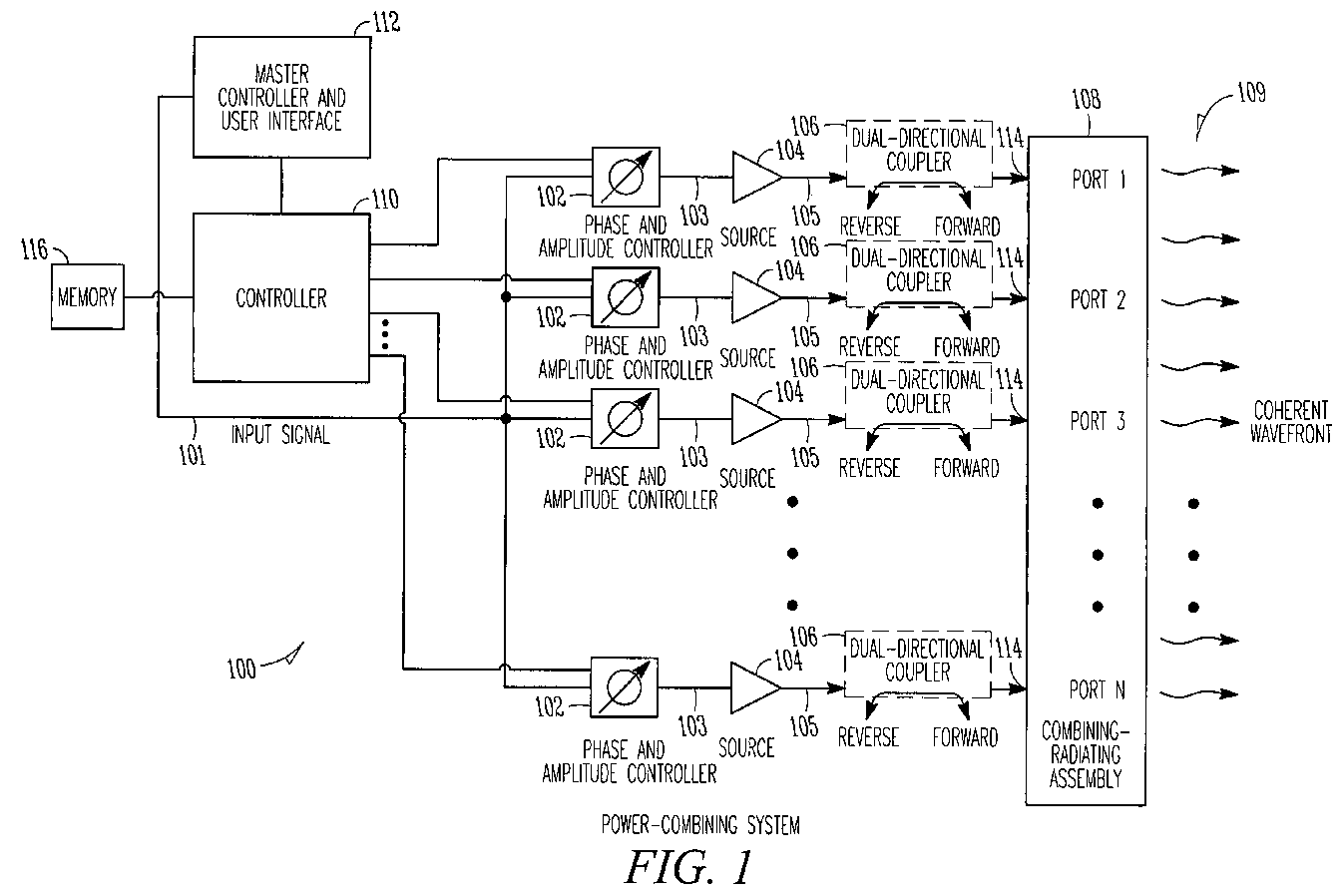
- FIG. 1 is a functional block diagram of a power-combining system in accordance with some embodiments of the present invention
- FIG. 2A illustrates a perspective view of a four port combining-radiating assembly in accordance with some embodiments of the present invention
- FIG. 2B illustrates a side view of a portion of a combining-radiating assembly in accordance with some embodiments of the present invention
- FIG. 3 illustrates a top view of an eight port combining-radiating assembly in accordance with some embodiments of the present invention.
- FIG. 4 is a functional block diagram of an active array antenna in accordance with some embodiments of the present invention.
- FIG. 1 is a functional block diagram of a power-combining system in accordance with some embodiments of the present invention.
- Power-combining system 100 may be used to generate coherent high-power wavefront 109.
- power-combining system 100 may include combining-radiating assembly 108 and phase controllers 102.
- Combining-radiating assembly 108 has a plurality of ports 114.
- Phase controllers 102 may generate signals with a predetermined phase shift for an associated one of ports 114.
- Power-combining system 100 may also include a plurality of coherent sources 104 to receive signals from an associated one of phase controllers 102 and to provide signals 105 to an associated port 114 with a predetermined phase shift.
- energy from ports 114 may be coherently combined and radiated by combining-radiating assembly 108 to generate coherent high-power wavefront 109.
- the term 'coherent wavefront' refers to a propagating electromagnetic wavefront of substantially constant phase.
- the energy provided to ports 114 is not spatially combined in free space, as in a spatial combiner or phased-array.
- the energy is concurrently combined within and radiated by combining-radiating assembly 108.
- combining-radiating assembly 108 may operate as an antenna that transmits the combined energy.
- combining-radiating assembly 108 may comprise a patch with ports 114 around the patch.
- the patch may combine signals 105 and may radiate coherent high-power wavefront 109.
- the patch may operate as an antenna that transmits the combined energy.
- ports 114 may be spaced uniformly around the patch.
- the patch may be circular and ports 114 may be uniformly spaced (e.g., radially) around the patch, although the scope of the invention is not limited in this respect as other shaped patches may also be suitable.
- the patch may comprise a conductive material having either a substantially circular shape or a substantially regular polygonal shape, although the scope of the invention is not limited in this respect. Some examples of the patch are discussed in more detail below.
- combining-radiating assembly 108 may comprise a linear-polarized horn antenna having an integrated coaxial-to-waveguide combiner to coherently combine energy from ports 114.
- the use of combining-radiating assembly 108 may lessen and possibly even eliminate the need for circuit-based power combiners.
- polarization diversity may be achieved by selectively setting the phase at each port 114 of combining-radiating assembly 108.
- control over the phase at each port 114 may allow power-combining system 100 to at least partially compensate for degradation and possibly even failure of one or more of the signal paths.
- power-combining system 100 may be used to transmit information wirelessly and may be part of a wireless communication system. In some other embodiments, power-combining system 100 may be part of an active array antenna system. These embodiments are described in more detail below.
- output signals 105 from coherent sources 104 may comprise either microwave or millimeter-wave frequency signals.
- each of coherent sources 104 may provide one of output signals 105 whose phase is set by that of an associated one of input signals 103 provided by an associated one of phase controllers 102.
- the microwave frequencies may generally range between approximately one and 30 gigahertz (GHz) and the millimeter-wave signals may generally range between approximately 30 and 300 GHz, although the scope of the invention is not limited in this respect.
- each of coherent sources 104 may comprise a phase-locked oscillator to provide one of output signals 105 that is phase-locked to an associated one of input signals 103.
- the output frequency and output phase of output signals 105 may be phase locked to common input signal 101, although the scope of the invention is not limited in this respect.
- each of coherent sources 104 may comprise up to several hundred or more small low-power amplifiers (e.g., one or more transistor cells) having relatively high input and output impedances (e.g., 50 Ohms), although the scope of the invention is not limited in this respect. These amplifiers may be matched using conventional microwave design techniques, although the scope of the invention is not limited in this respect.
- one or more of coherent sources 104 may comprise a traveling wave tube amplifier (TWTA) to provide output signals 105 whose phase is set by the phase of an associated one of input signals 103.
- TWTA traveling wave tube amplifier
- one or more of coherent sources 104 may comprise a klystron amplifier or a solid-state amplifier, although other amplifiers may also be suitable. In these embodiments, the phase at the output of coherent sources 104 is determined by the phase at the input.
- coherent sources 104 generate output signals 105 of substantially uniform amplitude for combining and radiating by combining-radiating assembly 108, although in other embodiments, the amplitude of output signals 105 may be varied. These embodiments are discussed in more detail below.
- power-combining system 100 may include controller 110 coupled to phase controllers 102 to set the phase of signals at ports 114 of combining-radiating assembly 108 to generate coherent high-power wavefront 109.
- controller 110 may be coupled to phase controllers 102 to set a phase progression of the signals at ports 114 to generate coherent high-power wavefront 109 with circular polarization.
- controller 110 may provide for on-the-fly polarization by setting a phase of the signals at ports 114 to selectively provide one of a right-hand circularly polarized wavefront, a left-hand circularly polarized wavefront, a horizontally polarized wavefront or a vertically polarized wavefront.
- controller 110 may set the phase shifts for each of phase controllers 102 based on an initial calibration for each port 114.
- memory 116 may store a predetermined phase offset and/or amplitude offset for each port 114 based on the initial calibration to provide the predetermined phase shift at each port 114 during operation.
- controller 110 may cause phase controllers 102 to offset the phase and/or amplitude for each port 114 based on the predetermined phase offset and amplitude offset stored in memory 116.
- phase controllers 102 may be phase and amplitude controllers.
- the phase and/or amplitude for each port 114 may be optimized so that reflected power at each port 114 is minimized. In these embodiments, rather than minimizing reflections and matching the input for each of ports 114 individually, reflections from all ports 114 may be minimized concurrently. In this way, maximum power may be transferred to combining-radiating assembly 108 for combining and radiating.
- power-combining system 100 may also include optional dual-directional couplers 106 in the signal path prior to ports 114.
- Dual directional couplers 106 may be used to measure incident and reflected power from ports 114 during operation. Data derived from these measurements may be used as part of a built-in-test system.
- Dual-directional couplers 106 may also be used to monitor reflected energy from ports 114 during calibration to determine the phase and/or amplitude offsets for use by controller 110.
- combining-radiating assembly 108 may have N ports 114 while possessing N-fold rotational symmetry. In these embodiments, combining-radiating assembly 108 may be geometrically invariant to rotations of 360/N degrees. In these embodiments, a phase progression of ⁇ 360 degrees divided by N may be set between ports 114 by controller 110 to generate coherent high-power wavefront 109 with either right-hand or left-hand circular polarization, depending on the sign of the phase progression.
- power-combining system 100 may be coupled to master controller and user interface 112.
- Master controller and user interface 112 may allow a user to select and set the type of polarization (i.e., right-hand circular, left-hand circular, vertical linear, horizontal linear) of coherent wavefront 109 as well as the power level of coherent wavefront 109.
- Master controller and user interface 112 may also be used during calibration.
- master controller and user interface 112 may be used to steer and/or direct coherent high-power wavefront 109 in various directions, although the scope of the invention is not limited in this respect. These embodiments are discussed in more detail below.
- FIG. 2A illustrates a perspective view of a four port combining-radiating assembly in accordance with some embodiments of the present invention.
- Four port combining-radiating assembly 200 may be suitable for use as combining-radiating assembly 108 ( FIG. 1 ), although other combining-radiating assemblies may also be suitable.
- Combining-radiating assembly 200 may include ports 204A, 204B, 204C and 204D and patch 202.
- Conductive strips 206 may couple one of ports 204A, 204B, 204C and 204D to patch 202.
- patch 202 may be fabricated on first insulating substrate 212 and conductive strips 206 may be fabricated on second insulating substrate 216.
- ports 204A, 204B, 204C and 204D may correspond to ports 114 ( FIG. 1 ).
- four ports 204A, 204B, 204C and 204D may generate coherent wavefront 109 ( FIG. 1 ) with right-hand circular polarization.
- controller 110 sets the relative phase at port 204A to zero degrees, the relative phase at port 204B to 90 degrees, the relative phase at port 204C to 180 degrees, and the relative phase at port 204D to 270 degrees.
- controller 110 to generate wavefront 109 ( FIG. 1 ) with left-hand circular polarization, controller 110 ( FIG.
- controller 110 sets the relative phase at port 204A to zero degrees, the relative phase at port 204B to -90 degrees, the relative phase at port 204C to -180 degrees, and the relative phase at port 204D to -270 degrees.
- controller 110 sets the relative phases at ports 204A and 204D to zero degrees and the relative phase at ports 204B and 204 C to 180 degrees.
- controller 110 sets the relative phases at ports 204A and 204B to zero degrees and the relative phase at port 204C and 204D to 180 degrees.
- ports 204A, 204B, 204C and 204D when four ports 204A, 204B, 204C and 204D are used to generate coherent wavefront 109 ( FIG. 1 ) with either horizontal or vertical linear polarization, ports 204A, 204B, 204C and 204D may be spaced substantially ninety degrees apart from each other around patch 202 as illustrated in FIG. 2A , although the scope of the invention is not limited in this respect. Controller 110 ( FIG.
- the linear polarization may be either horizontal or vertical depending on which adjacent ports are provided the in-phase signals.
- the amplitude of the signals at each of the four ports may be the same, although the scope of the invention is not limited in this respect.
- patch 202 may have a circular shape, as illustrated in FIG. 2A .
- patch 202 may have a rectangular or square shape with multiple ports arranged on opposite sides of the patch.
- the phases of the signals provided at the ports may be selected to provide a linearly-polarized wavefront.
- the rectangular or square shaped patch may have four or more ports.
- N eight ports may be used to generate a wavefront with either right-hand or left-hand circular polarization. In some other eight port embodiments, eight ports may be used to generate a coherent wavefront with a linear polarization. These embodiments are described in more detail below.
- FIG. 2B illustrates a side view of a portion of a combining-radiating assembly in accordance with some embodiments of the present invention.
- FIG. 2B illustrates first non-conductive substrate 212 having patch 202 disposed thereon, and second non-conductive substrate 216 having conductive strips 206 disposed thereon.
- each conductive strip 206 may signal-couple one of ports 204 to patch 202.
- Second non-conductive substrate 216 may have ground plane 218 disposed on the side opposite of conductive strips 206.
- Port 204, illustrated in FIG. 2B may correspond to any one or more of ports 204A - 204D ( FIG. 2A ).
- first and second non-conductive substrates 212 & 216 may comprise printed circuit boards (PCBs), such as Duroid or alumina, although other non-conductive substrate materials may also be suitable.
- PCBs printed circuit boards
- patch 202, conductive strips 206 and ground plane 218 may comprise a conductive material such as copper, gold, aluminum and/or silver, although the scope of the invention is not limited in this respect.
- ports 204 may comprise electromagnetically-coupled ports.
- electromagnetic signals 203 may be coupled between conductive strips 206 and patch 202.
- each port 204 may comprise an open-ended conductive strip 206 disposed on non-conductive substrate 216 to couple electromagnetic energy from each conductive strip 206 to patch 202.
- open-ended conductive strips 206 may extend and terminate under patch 202 as illustrated.
- open-ended conductive strips 206 may be electrically insulated from patch 202, although the scope of the invention is not limited in this respect.
- open-ended conductive strips 206 may comprise microstrip feed lines, although the scope of the invention is not limited in this respect.
- ports 204 may comprise a connector, such as an SMA connector, although the scope of the invention is not limited in this respect.
- the center conductor of each connector may couple with one of conductive strips 206.
- FIG. 3 illustrates a top view of an eight port combining-radiating assembly in accordance with some embodiments of the present invention.
- Eight port combining-radiating assembly 300 may be suitable for use as combining-radiating assembly 108 ( FIG. 1 ), although other combining-radiating assemblies may also be used.
- Eight port combining-radiating assembly 300 may include patch 302, which may be similar to patch 202 ( FIGs. 2A & 2B ), conductive strips 306, which may be similar to conductive strips 206 ( FIGs. 2A & 2B ), and ports 304A - 304H, which may be similar to ports 204A - 204D ( FIG. 2A ) or port 204 ( FIG. 2B ).
- patch 302 may be fabricated on a first insulating substrate, which may be similar to first insulating substrate 212 ( FIG. 2B ), and conductive strips 306 may be fabricated on a second insulating substrate, which may be similar to second insulating substrate 216 ( FIG. 2B ), although the scope of the invention is not limited in this respect.
- controller 110 sets the relative phase at port 304A to zero degrees, the relative phase at port 304B to 45 degrees, the relative phase at port 304C to 90 degrees, the relative phase at port 304D to 135 degrees, the relative phase at port 304E to 180 degrees, the relative phase at port 304F to 225 degrees, the relative phase at port 304G to 270 degrees, and the relative phase at port 304H to 315 degrees.
- controller 110 to generate wavefront 109 ( FIG. 1 ) with left-hand circular polarization, controller 110 ( FIG.
- the relative phase at port 304A sets the relative phase at port 304A to zero degrees, the relative phase at port 304B to -45 degrees, the relative phase at port 304C to -90 degrees, the relative phase at port 304D to -135 degrees, the relative phase at port 304E to -180 degrees, the relative phase at port 304F to -225 degrees, and the relative phase at port 304G to -270 degrees, and the relative phase at port 304H to -315 degrees.
- the amplitude of the signals at each of ports 304A - 304H may be the same, although the scope of the invention is not limited in this respect.
- patch 302 is illustrated as having a circular shape, the scope of the invention is not limited in this respect. In alternate embodiments, patch 302 may have regular polygonal shape (e.g., octagonal).
- ports 304A - 304H may be used to generate wavefront 109 ( FIG. 1 ) with either horizontal or vertical linear polarization.
- controller 110 FIG. 1
- alternate ports may be set to lower amplitude levels.
- FIG. 4 is a functional block diagram of an active array antenna system in accordance with some embodiments of the present invention.
- Active array antenna system 400 may generate high-power coherent wavefront 409.
- Active array antenna system 400 may comprise combining-radiating assembly 408 comprising a plurality of combining-radiating elements 402.
- Each combining-radiating element 402 may have a plurality of ports.
- Active array antenna system 400 may also include a plurality of power-generating systems 412.
- Each power-generating system 412 may be associated with one of combining-radiating elements 402 and may generate signals for each port of the associated combining-radiating elements 402.
- each combining-radiating element 402 may comprise a conductive patch, such as patch 202 ( FIG. 2A ) or patch 302 ( FIG. 3 ) although other types of combining-radiating element or patches may also be suitable.
- combining-radiating assembly 408 may comprise an array of individual combining-radiating assemblies, such as an array of individual combining-radiating assembly 108 ( FIG. 1 ).
- Each power-generating system 412 and an associated one of individual combining-radiating assembly 108 ( FIG. 1 ) may correspond to power-combining system 100 ( FIG. 1 ).
- combining-radiating assembly 408 is illustrated as a 4X4 array of sixteen individual combining-radiating assemblies, although the scope of the invention is not limited in this respect as almost any number of combining-radiating assemblies may be used.
- the coherent wavefront generated by each individual combining-radiating assembly may be combined in-phase.
- master controller and user interface 112 may steer and/or direct combined high-power coherent wavefront 409. Accordingly, in these embodiments, a large amount of coherent energy may be directed toward a target.
- master controller and user interface 112 may include one or more controllers, such as controller 110 ( FIG. 1 ), to provide for on-the-fly polarization by setting a phase of the signals at individual ports 114 ( FIG. 1 ) of each combining-radiating elements 402 to selectively provide one of a right-hand circularly polarized wavefront, a left-hand circularly polarized wavefront, a horizontally polarized wavefront or a vertically polarized wavefront generated by each combining-radiating element 402.
- this port-to port phase controls the polarization of the energy generated by each combining-radiating element 402.
- master controller and user interface 112 may further control the element-to-element phase (i.e., the phase between combining-radiating elements 402) to determine the beam-steering direction, although the scope of the invention is not limited in this respect.
- power-combining system 100 FIG. 1
- active array antenna system 400 FIG. 4
- the functional elements may be combined and may be implemented by combinations of software-configured elements, such as processing elements including digital signal processors (DSPs), and/or other hardware elements.
- DSPs digital signal processors
- some elements may comprise one or more microprocessors, DSPs, application specific integrated circuits (ASICs), and combinations of various hardware and logic circuitry for performing at least the functions described herein.
- the functional elements of system 100 ( FIG. 1 ) and system 400 ( FIG. 4 ) may refer to one or more processes operating on one or more processing elements.
Landscapes
- Physics & Mathematics (AREA)
- Electromagnetism (AREA)
- Variable-Direction Aerials And Aerial Arrays (AREA)
Abstract
Description
- Some embodiments of the present invention pertain to the generation and transmission of microwave and/or millimeter wave energy. Some embodiments relate to power combining. Some embodiments relate to wireless communication systems. Some embodiments relate to active array antenna systems.
- Many conventional power-combining techniques generate high-power signal levels by combining the outputs of multiple transistor amplifiers or transistor-amplifier cells. These conventional techniques require complex matching networks due to the very low output impedances of the high-power devices. Other conventional power-combining techniques use stripline or microstrip circuits to combine the outputs of multiple amplifiers. These conventional power-combining techniques require significant circuit area compared with the area occupied by the amplifier devices. The failure of an amplifier device may result in an impedance mismatch that may significantly degrade the performance of the power combiner.
- Thus, there are general needs for systems that can generate high-power signal levels that do not require complex matching networks. There are also general needs for systems that can generate high-power signal levels that do not require significant circuit area as compared with the area occupied by the amplifier.
-
FIG. 1 is a functional block diagram of a power-combining system in accordance with some embodiments of the present invention; -
FIG. 2A illustrates a perspective view of a four port combining-radiating assembly in accordance with some embodiments of the present invention; -
FIG. 2B illustrates a side view of a portion of a combining-radiating assembly in accordance with some embodiments of the present invention; -
FIG. 3 illustrates a top view of an eight port combining-radiating assembly in accordance with some embodiments of the present invention; and -
FIG. 4 is a functional block diagram of an active array antenna in accordance with some embodiments of the present invention. - The following description and the drawings sufficiently illustrate specific embodiments of the invention to enable those skilled in the art to practice them. Other embodiments may incorporate structural, logical, electrical, process, and other changes. Examples merely typify possible variations. Portions and features of some embodiments may be included in, or substituted for, those of other embodiments. Embodiments of the invention set forth in the claims encompass all available equivalents of those claims. Embodiments of the invention may be referred to herein, individually or collectively, by the term "invention" merely for convenience and without intending to limit the scope of this application to any single invention or inventive concept if more than one is in fact disclosed.
-
FIG. 1 is a functional block diagram of a power-combining system in accordance with some embodiments of the present invention. Power-combiningsystem 100 may be used to generate coherent high-power wavefront 109. In these embodiments, power-combiningsystem 100 may include combining-radiating assembly 108 andphase controllers 102. Combining-radiating assembly 108 has a plurality ofports 114.Phase controllers 102 may generate signals with a predetermined phase shift for an associated one ofports 114. Power-combiningsystem 100 may also include a plurality ofcoherent sources 104 to receive signals from an associated one ofphase controllers 102 and to providesignals 105 to an associatedport 114 with a predetermined phase shift. In these embodiments, energy fromports 114 may be coherently combined and radiated by combining-radiating assembly 108 to generate coherent high-power wavefront 109. As used herein, the term 'coherent wavefront' refers to a propagating electromagnetic wavefront of substantially constant phase. - In accordance with embodiments of the present invention, the energy provided to
ports 114 is not spatially combined in free space, as in a spatial combiner or phased-array. The energy is concurrently combined within and radiated by combining-radiatingassembly 108. In some embodiments, combining-radiating assembly 108 may operate as an antenna that transmits the combined energy. - In some embodiments, combining-
radiating assembly 108 may comprise a patch withports 114 around the patch. The patch may combinesignals 105 and may radiate coherent high-power wavefront 109. In these embodiments, the patch may operate as an antenna that transmits the combined energy. In some embodiments,ports 114 may be spaced uniformly around the patch. In some embodiments, the patch may be circular andports 114 may be uniformly spaced (e.g., radially) around the patch, although the scope of the invention is not limited in this respect as other shaped patches may also be suitable. In some of these embodiments, the patch may comprise a conductive material having either a substantially circular shape or a substantially regular polygonal shape, although the scope of the invention is not limited in this respect. Some examples of the patch are discussed in more detail below. In some alternate embodiments, combining-radiating assembly 108 may comprise a linear-polarized horn antenna having an integrated coaxial-to-waveguide combiner to coherently combine energy fromports 114. - In some embodiments, the use of combining-radiating
assembly 108 may lessen and possibly even eliminate the need for circuit-based power combiners. Furthermore, in some embodiments, polarization diversity may be achieved by selectively setting the phase at eachport 114 of combining-radiatingassembly 108. In addition, in some embodiments, control over the phase at eachport 114 may allow power-combiningsystem 100 to at least partially compensate for degradation and possibly even failure of one or more of the signal paths. - In some embodiments, power-combining
system 100 may be used to transmit information wirelessly and may be part of a wireless communication system. In some other embodiments, power-combiningsystem 100 may be part of an active array antenna system. These embodiments are described in more detail below. - In some embodiments,
output signals 105 fromcoherent sources 104 may comprise either microwave or millimeter-wave frequency signals. In some embodiments, each ofcoherent sources 104 may provide one ofoutput signals 105 whose phase is set by that of an associated one ofinput signals 103 provided by an associated one ofphase controllers 102. In these embodiments, the microwave frequencies may generally range between approximately one and 30 gigahertz (GHz) and the millimeter-wave signals may generally range between approximately 30 and 300 GHz, although the scope of the invention is not limited in this respect. - In some embodiments, each of
coherent sources 104 may comprise a phase-locked oscillator to provide one ofoutput signals 105 that is phase-locked to an associated one ofinput signals 103. In some embodiments, the output frequency and output phase ofoutput signals 105 may be phase locked tocommon input signal 101, although the scope of the invention is not limited in this respect. - In some embodiments, each of
coherent sources 104 may comprise up to several hundred or more small low-power amplifiers (e.g., one or more transistor cells) having relatively high input and output impedances (e.g., 50 Ohms), although the scope of the invention is not limited in this respect. These amplifiers may be matched using conventional microwave design techniques, although the scope of the invention is not limited in this respect. In some other embodiments, one or more ofcoherent sources 104 may comprise a traveling wave tube amplifier (TWTA) to provideoutput signals 105 whose phase is set by the phase of an associated one ofinput signals 103. In some other embodiments, one or more ofcoherent sources 104 may comprise a klystron amplifier or a solid-state amplifier, although other amplifiers may also be suitable. In these embodiments, the phase at the output ofcoherent sources 104 is determined by the phase at the input. - In some of these embodiments,
coherent sources 104 generateoutput signals 105 of substantially uniform amplitude for combining and radiating by combining-radiating assembly 108, although in other embodiments, the amplitude ofoutput signals 105 may be varied. These embodiments are discussed in more detail below. - As illustrated in
FIG. 1 , power-combiningsystem 100 may includecontroller 110 coupled tophase controllers 102 to set the phase of signals atports 114 of combining-radiatingassembly 108 to generate coherent high-power wavefront 109. In some embodiments,controller 110 may be coupled tophase controllers 102 to set a phase progression of the signals atports 114 to generate coherent high-power wavefront 109 with circular polarization. - In some embodiments,
controller 110 may provide for on-the-fly polarization by setting a phase of the signals atports 114 to selectively provide one of a right-hand circularly polarized wavefront, a left-hand circularly polarized wavefront, a horizontally polarized wavefront or a vertically polarized wavefront. - In some embodiments,
controller 110 may set the phase shifts for each ofphase controllers 102 based on an initial calibration for eachport 114. In some embodiments,memory 116 may store a predetermined phase offset and/or amplitude offset for eachport 114 based on the initial calibration to provide the predetermined phase shift at eachport 114 during operation. In these embodiments,controller 110 may causephase controllers 102 to offset the phase and/or amplitude for eachport 114 based on the predetermined phase offset and amplitude offset stored inmemory 116. In some of these embodiments,phase controllers 102 may be phase and amplitude controllers. In these embodiments, during calibration, the phase and/or amplitude for eachport 114 may be optimized so that reflected power at eachport 114 is minimized. In these embodiments, rather than minimizing reflections and matching the input for each ofports 114 individually, reflections from allports 114 may be minimized concurrently. In this way, maximum power may be transferred to combining-radiatingassembly 108 for combining and radiating. - In some embodiments, power-combining
system 100 may also include optional dual-directional couplers 106 in the signal path prior toports 114. Dualdirectional couplers 106 may be used to measure incident and reflected power fromports 114 during operation. Data derived from these measurements may be used as part of a built-in-test system. Dual-directional couplers 106 may also be used to monitor reflected energy fromports 114 during calibration to determine the phase and/or amplitude offsets for use bycontroller 110. - In some embodiments, combining-radiating
assembly 108 may haveN ports 114 while possessing N-fold rotational symmetry. In these embodiments, combining-radiatingassembly 108 may be geometrically invariant to rotations of 360/N degrees. In these embodiments, a phase progression of ±360 degrees divided by N may be set betweenports 114 bycontroller 110 to generate coherent high-power wavefront 109 with either right-hand or left-hand circular polarization, depending on the sign of the phase progression. - In some embodiments, power-combining
system 100 may be coupled to master controller anduser interface 112. Master controller anduser interface 112 may allow a user to select and set the type of polarization (i.e., right-hand circular, left-hand circular, vertical linear, horizontal linear) ofcoherent wavefront 109 as well as the power level ofcoherent wavefront 109. Master controller anduser interface 112 may also be used during calibration. In some embodiments, master controller anduser interface 112 may be used to steer and/or direct coherent high-power wavefront 109 in various directions, although the scope of the invention is not limited in this respect. These embodiments are discussed in more detail below. -
FIG. 2A illustrates a perspective view of a four port combining-radiating assembly in accordance with some embodiments of the present invention. Four port combining-radiatingassembly 200 may be suitable for use as combining-radiating assembly 108 (FIG. 1 ), although other combining-radiating assemblies may also be suitable. Combining-radiatingassembly 200 may includeports patch 202.Conductive strips 206 may couple one ofports patch 202 may be fabricated on first insulatingsubstrate 212 andconductive strips 206 may be fabricated on second insulatingsubstrate 216. In these embodiments,ports FIG. 1 ). - In some four-port embodiments (i.e., N=4), four
ports FIG. 1 ) with right-hand circular polarization. In these embodiments, controller 110 (FIG. 1 ) sets the relative phase atport 204A to zero degrees, the relative phase atport 204B to 90 degrees, the relative phase atport 204C to 180 degrees, and the relative phase atport 204D to 270 degrees. In these four-port embodiments, to generate wavefront 109 (FIG. 1 ) with left-hand circular polarization, controller 110 (FIG. 1 ) sets the relative phase atport 204A to zero degrees, the relative phase atport 204B to -90 degrees, the relative phase atport 204C to -180 degrees, and the relative phase atport 204D to -270 degrees. In these same four-port embodiments, to generate wavefront 109 (FIG. 1 ) with horizontal linear polarization, controller 110 (FIG. 1 ) sets the relative phases atports ports FIG. 1 ) with vertical linear polarization, controller 110 (FIG. 1 ) sets the relative phases atports port - In these four-port embodiments when four
ports FIG. 1 ) with either horizontal or vertical linear polarization,ports patch 202 as illustrated inFIG. 2A , although the scope of the invention is not limited in this respect. Controller 110 (FIG. 1 ) may set the relative phase of signals provided to two adjacent ports (i.e.,ports ports ports FIG. 1 ) having a linear polarization. In these embodiments, the linear polarization may be either horizontal or vertical depending on which adjacent ports are provided the in-phase signals. In these four-port embodiments that generate coherent wavefront 109 (FIG. 1 ) with a linear polarization, the amplitude of the signals at each of the four ports may be the same, although the scope of the invention is not limited in this respect. - In some embodiments,
patch 202 may have a circular shape, as illustrated inFIG. 2A . In some other embodiments,patch 202 may have a rectangular or square shape with multiple ports arranged on opposite sides of the patch. In these other embodiments, the phases of the signals provided at the ports may be selected to provide a linearly-polarized wavefront. In these embodiments, the rectangular or square shaped patch may have four or more ports. - In some eight port embodiments (N=8), eight ports may be used to generate a wavefront with either right-hand or left-hand circular polarization. In some other eight port embodiments, eight ports may be used to generate a coherent wavefront with a linear polarization. These embodiments are described in more detail below.
-
FIG. 2B illustrates a side view of a portion of a combining-radiating assembly in accordance with some embodiments of the present invention.FIG. 2B illustrates firstnon-conductive substrate 212 havingpatch 202 disposed thereon, and secondnon-conductive substrate 216 havingconductive strips 206 disposed thereon. In some embodiments, eachconductive strip 206 may signal-couple one ofports 204 topatch 202. Secondnon-conductive substrate 216 may have ground plane 218 disposed on the side opposite ofconductive strips 206.Port 204, illustrated inFIG. 2B , may correspond to any one or more ofports 204A - 204D (FIG. 2A ). - In some embodiments, first and second
non-conductive substrates 212 & 216 may comprise printed circuit boards (PCBs), such as Duroid or alumina, although other non-conductive substrate materials may also be suitable. In some embodiments,patch 202,conductive strips 206 and ground plane 218 may comprise a conductive material such as copper, gold, aluminum and/or silver, although the scope of the invention is not limited in this respect. - In some embodiments,
ports 204 may comprise electromagnetically-coupled ports. In these embodiments, electromagnetic signals 203 may be coupled betweenconductive strips 206 andpatch 202. In these embodiments, eachport 204 may comprise an open-endedconductive strip 206 disposed onnon-conductive substrate 216 to couple electromagnetic energy from eachconductive strip 206 to patch 202. In these embodiments, open-endedconductive strips 206 may extend and terminate underpatch 202 as illustrated. In these electromagnetically-coupled embodiments, open-endedconductive strips 206 may be electrically insulated frompatch 202, although the scope of the invention is not limited in this respect. In some of these embodiments, open-endedconductive strips 206 may comprise microstrip feed lines, although the scope of the invention is not limited in this respect. - In the embodiments illustrated in
FIGs. 2A and 2B ,ports 204 may comprise a connector, such as an SMA connector, although the scope of the invention is not limited in this respect. The center conductor of each connector may couple with one ofconductive strips 206. -
FIG. 3 illustrates a top view of an eight port combining-radiating assembly in accordance with some embodiments of the present invention. Eight port combining-radiatingassembly 300 may be suitable for use as combining-radiating assembly 108 (FIG. 1 ), although other combining-radiating assemblies may also be used. Eight port combining-radiatingassembly 300 may includepatch 302, which may be similar to patch 202 (FIGs. 2A & 2B ),conductive strips 306, which may be similar to conductive strips 206 (FIGs. 2A & 2B ), andports 304A - 304H, which may be similar toports 204A - 204D (FIG. 2A ) or port 204 (FIG. 2B ). In these embodiments,patch 302 may be fabricated on a first insulating substrate, which may be similar to first insulating substrate 212 (FIG. 2B ), andconductive strips 306 may be fabricated on a second insulating substrate, which may be similar to second insulating substrate 216 (FIG. 2B ), although the scope of the invention is not limited in this respect. - In these eight port embodiments (N=8), to generate wavefront 109 (
FIG. 1 ) with right-hand circular polarization, controller 110 (FIG. 1 ) sets the relative phase atport 304A to zero degrees, the relative phase atport 304B to 45 degrees, the relative phase atport 304C to 90 degrees, the relative phase atport 304D to 135 degrees, the relative phase atport 304E to 180 degrees, the relative phase atport 304F to 225 degrees, the relative phase atport 304G to 270 degrees, and the relative phase atport 304H to 315 degrees. In these eight port embodiments, to generate wavefront 109 (FIG. 1 ) with left-hand circular polarization, controller 110 (FIG. 1 ) sets the relative phase atport 304A to zero degrees, the relative phase atport 304B to -45 degrees, the relative phase atport 304C to -90 degrees, the relative phase atport 304D to -135 degrees, the relative phase atport 304E to -180 degrees, the relative phase atport 304F to -225 degrees, and the relative phase atport 304G to -270 degrees, and the relative phase atport 304H to -315 degrees. In these eight port embodiments that generate a coherent wavefront with circular polarization, the amplitude of the signals at each ofports 304A - 304H may be the same, although the scope of the invention is not limited in this respect. - Although
patch 302 is illustrated as having a circular shape, the scope of the invention is not limited in this respect. In alternate embodiments,patch 302 may have regular polygonal shape (e.g., octagonal). - In some alternate embodiments,
ports 304A - 304H may be used to generate wavefront 109 (FIG. 1 ) with either horizontal or vertical linear polarization. In these embodiments, controller 110 (FIG. 1 ) may adjust (e.g., reduce) the amplitude of signals 105 (FIG. 1 ) provided to some of the ports, although the scope of the invention is not limited in this respect. For example, alternate ports may be set to lower amplitude levels. -
FIG. 4 is a functional block diagram of an active array antenna system in accordance with some embodiments of the present invention. Activearray antenna system 400 may generate high-powercoherent wavefront 409. Activearray antenna system 400 may comprise combining-radiatingassembly 408 comprising a plurality of combining-radiatingelements 402. Each combining-radiatingelement 402 may have a plurality of ports. Activearray antenna system 400 may also include a plurality of power-generatingsystems 412. Each power-generatingsystem 412 may be associated with one of combining-radiatingelements 402 and may generate signals for each port of the associated combining-radiatingelements 402. In some embodiments, each combining-radiatingelement 402 may comprise a conductive patch, such as patch 202 (FIG. 2A ) or patch 302 (FIG. 3 ) although other types of combining-radiating element or patches may also be suitable. - In the embodiments illustrated in
FIG. 4 , combining-radiatingassembly 408 may comprise an array of individual combining-radiating assemblies, such as an array of individual combining-radiating assembly 108 (FIG. 1 ). Each power-generatingsystem 412 and an associated one of individual combining-radiating assembly 108 (FIG. 1 ) may correspond to power-combining system 100 (FIG. 1 ). - In
FIG. 4 , combining-radiatingassembly 408 is illustrated as a 4X4 array of sixteen individual combining-radiating assemblies, although the scope of the invention is not limited in this respect as almost any number of combining-radiating assemblies may be used. In these embodiments, the coherent wavefront generated by each individual combining-radiating assembly may be combined in-phase. In some embodiments, master controller anduser interface 112 may steer and/or direct combined high-powercoherent wavefront 409. Accordingly, in these embodiments, a large amount of coherent energy may be directed toward a target. - In some embodiments, master controller and
user interface 112 may include one or more controllers, such as controller 110 (FIG. 1 ), to provide for on-the-fly polarization by setting a phase of the signals at individual ports 114 (FIG. 1 ) of each combining-radiatingelements 402 to selectively provide one of a right-hand circularly polarized wavefront, a left-hand circularly polarized wavefront, a horizontally polarized wavefront or a vertically polarized wavefront generated by each combining-radiatingelement 402. In these embodiments, this port-to port phase controls the polarization of the energy generated by each combining-radiatingelement 402. In these embodiments, master controller anduser interface 112 may further control the element-to-element phase (i.e., the phase between combining-radiating elements 402) to determine the beam-steering direction, although the scope of the invention is not limited in this respect. - Although power-combining system 100 (
FIG. 1 ) and active array antenna system 400 (FIG. 4 ) are illustrated as having several separate functional elements, one or more of the functional elements may be combined and may be implemented by combinations of software-configured elements, such as processing elements including digital signal processors (DSPs), and/or other hardware elements. For example, some elements may comprise one or more microprocessors, DSPs, application specific integrated circuits (ASICs), and combinations of various hardware and logic circuitry for performing at least the functions described herein. In some embodiments, the functional elements of system 100 (FIG. 1 ) and system 400 (FIG. 4 ) may refer to one or more processes operating on one or more processing elements. - The Abstract is provided to comply with 37 C.F.R. Section 1.72(b) requiring an abstract that will allow the reader to ascertain the nature and gist of the technical disclosure. It is submitted with the understanding that it will not be used to limit or interpret the scope or meaning of the claims.
- In the foregoing detailed description, various features are occasionally grouped together in a single embodiment for the purpose of streamlining the disclosure. This method of disclosure is not to be interpreted as reflecting an intention that the claimed embodiments of the subject matter require more features than are expressly recited in each claim. Rather, as the following claims reflect, invention may lie in less than all features of a single disclosed embodiment. Thus, the following claims are hereby incorporated into the detailed description, with each claim standing on its own as a separate preferred embodiment.
Claims (10)
- A power-combining system (100) for generating a coherent high-power wavefront comprising:a combining-radiating assembly (108) having a plurality of ports (204);phase controllers (102) to generate signals with a predetermined phase shift for an associated one of the ports; anda plurality of coherent sources (104) to receive signals from an associated one of the phase controllers (102) and to provide the signals to an associated port (204) of the combining-radiating assembly (108) with the predetermined phase shifts,wherein energy from the ports is coherently combined and radiated by combining-radiating assembly (108) to provide a coherent wavefront (109).
- The power combiner system of claim 1 wherein the combining-radiating assembly (108) comprises a conductive patch (202) having the plurality of ports (204) spaced around the patch (202),
wherein energy from the ports is coherently combined and radiated by combining-radiating assembly (108) the patch (202) to provide the coherent wavefront (109), and
wherein the patch has a circular shape and the ports are spaced uniformly around the patch. - The power combiner system of claim 2 wherein each of the coherent sources (104) comprises a phase-locked oscillator to provide an output signal (105) that is phase-locked to the associated input signal (103).
- The power combiner system of claim 2 further comprising a controller (110),
wherein the combining-radiating assembly (108) has four ports (204) spaced substantially ninety degrees apart from each other around the patch (202), and
wherein the controller (110) sets a relative phase of signals provided to two adjacent ports to be substantially in phase with each other, and sets the relative phase of the signals provided to two opposite ports to be substantially 180 degrees to generate the wavefront having a linear polarization. - The power combiner system of claim 2 wherein the combining-radiating assembly (108) comprises:a first non-conductive substrate (212) having the patch 202 disposed thereon; anda second non-conductive substrate (216) having conductive strips (206) disposed thereon, each conductive strip signal-coupling one of the ports (204) to the patch (202), the second non-conductive substrate (216) further having a ground-plane (218) disposed on a side opposite the conductive strips (206).
- The power combiner system of claim 5 wherein the ports (204) of the combining-radiating assembly (108) comprise electromagnetically-coupled ports,
wherein each port (204) comprises an open-ended conductive strip (206) disposed on a non-conductive substrate (216) to couple electromagnetic energy to the patch (202), and
wherein the open-ended conductive strips (206) extend and terminate under the patch (202). - A method for generating a coherent high-power wavefront comprising:generating high-power signals with a predetermined phase shift for each of a plurality of ports; andconcurrently combining and radiating the signals received at each of the ports to provide a coherent high-power wavefront (109).
- The method of claim 7 wherein concurrently combining and radiating the signals received at each of the ports with a conductive patch (202),
wherein the plurality of ports (204) are spaced uniformly around the patch (202) to provide the coherent high-power wavefront (109),
wherein generating comprises setting a phase progression of the signals at the ports around the patch to generate a circularly polarized wavefront (109),
wherein the patch comprises a conductive material having either a substantially circular shape or a substantially regular polygonal shape,
wherein the concurrently combining and radiating is performed by a combining-radiating assembly (108) having N ports,
wherein the phase progression set by the controller (110) between the ports is 360 degrees divided by N, and
wherein N is an integer greater than or equal to 3 inclusive. - An active array antenna for generating a high-power coherent wavefront (409) comprising:a combining-radiating assembly (408) comprising a plurality of combining-radiating elements (402) having a plurality of ports;a plurality of power-combining systems (412), each associated with one of the combining-radiating elements (402) to generate signals for each port of the associated patch (402),wherein each power-combining system comprises a phase controller (102) to generate signals with a predetermined phase shift for an associated one of the ports and a plurality of coherent sources (104) to receive signals from an associated one of the phase controllers (102) and to provide the signals to an associated port (204) of the combining-radiating assembly (108) with the predetermined phase shifts,
wherein energy from the ports is coherently combined and radiated by the patches (202) to provide a coherent wavefront. - The active array antenna of claim 9 wherein each of the combining-radiating elements comprises:a first non-conductive substrate (212) having a patch 202 disposed thereon; anda second non-conductive substrate (216) having conductive strips (206) disposed thereon, each conductive strip signal-coupling one of the ports (204) to the patch (202), the second non-conductive substrate (216) further having a ground-plane (218) disposed on a side opposite the conductive strips (206),wherein the ports (204) of each of the combining-radiating elements comprise electromagnetically-coupled ports,
wherein each port (204) comprises an open-ended conductive strip (206) disposed on a non-conductive substrate (216) to couple electromagnetic energy to the patch (202), and
wherein the open-ended conductive strips (206) extend and terminate under the patch (202).
Priority Applications (1)
| Application Number | Priority Date | Filing Date | Title |
|---|---|---|---|
| EP08250593.4A EP2093832B1 (en) | 2008-02-20 | 2008-02-20 | Power combining and energy radiating system and method |
Applications Claiming Priority (1)
| Application Number | Priority Date | Filing Date | Title |
|---|---|---|---|
| EP08250593.4A EP2093832B1 (en) | 2008-02-20 | 2008-02-20 | Power combining and energy radiating system and method |
Publications (2)
| Publication Number | Publication Date |
|---|---|
| EP2093832A1 true EP2093832A1 (en) | 2009-08-26 |
| EP2093832B1 EP2093832B1 (en) | 2015-09-30 |
Family
ID=39382613
Family Applications (1)
| Application Number | Title | Priority Date | Filing Date |
|---|---|---|---|
| EP08250593.4A Active EP2093832B1 (en) | 2008-02-20 | 2008-02-20 | Power combining and energy radiating system and method |
Country Status (1)
| Country | Link |
|---|---|
| EP (1) | EP2093832B1 (en) |
Cited By (2)
| Publication number | Priority date | Publication date | Assignee | Title |
|---|---|---|---|---|
| FR3062524A1 (en) * | 2017-02-01 | 2018-08-03 | Thales | ELEMENTARY ANTENNA WITH A PLANAR RADIANT DEVICE |
| EP4325881A4 (en) * | 2021-05-26 | 2024-06-05 | Chengdu T-Ray Technology Co., Ltd. | STRIP ANTENNA STRUCTURE AND COMMUNICATION DEVICE |
Citations (4)
| Publication number | Priority date | Publication date | Assignee | Title |
|---|---|---|---|---|
| US4755829A (en) | 1987-02-20 | 1988-07-05 | The United States Of America As Represented By The Secretary Of The Navy | Space power combiner |
| US20030179139A1 (en) | 2002-03-21 | 2003-09-25 | Nemit Jeffery T. | Wide bandwidth phased array antenna system |
| US20050073461A1 (en) | 2003-10-02 | 2005-04-07 | Toyon Research Corporation | Switched-resonance antenna phase shifter and phased array incorporation same |
| US20060007044A1 (en) | 2004-07-01 | 2006-01-12 | Crouch David D | Multiple-port patch antenna |
Family Cites Families (1)
| Publication number | Priority date | Publication date | Assignee | Title |
|---|---|---|---|---|
| SE516105C2 (en) * | 1999-06-11 | 2001-11-19 | Allgon Ab | A method for controlling the radiation pattern of an antenna, antenna system and radio communication device |
-
2008
- 2008-02-20 EP EP08250593.4A patent/EP2093832B1/en active Active
Patent Citations (4)
| Publication number | Priority date | Publication date | Assignee | Title |
|---|---|---|---|---|
| US4755829A (en) | 1987-02-20 | 1988-07-05 | The United States Of America As Represented By The Secretary Of The Navy | Space power combiner |
| US20030179139A1 (en) | 2002-03-21 | 2003-09-25 | Nemit Jeffery T. | Wide bandwidth phased array antenna system |
| US20050073461A1 (en) | 2003-10-02 | 2005-04-07 | Toyon Research Corporation | Switched-resonance antenna phase shifter and phased array incorporation same |
| US20060007044A1 (en) | 2004-07-01 | 2006-01-12 | Crouch David D | Multiple-port patch antenna |
Non-Patent Citations (1)
| Title |
|---|
| TANAKA T ET AL: "CIRCULARLY POLARIZED PRINTED ANTENNA COMBINING SLOTS AND PATCH", IEICE TRANSACTIONS ON COMMUNICATIONS, COMMUNICATIONS SOCIETY, TOKYO, JP, vol. E90B, no. 3, 1 March 2007 (2007-03-01), pages 621 - 629, XP001541881, ISSN: 0916-8516 * |
Cited By (7)
| Publication number | Priority date | Publication date | Assignee | Title |
|---|---|---|---|---|
| FR3062524A1 (en) * | 2017-02-01 | 2018-08-03 | Thales | ELEMENTARY ANTENNA WITH A PLANAR RADIANT DEVICE |
| WO2018141882A1 (en) * | 2017-02-01 | 2018-08-09 | Thales | Elementary antenna comprising a planar radiating device |
| CN110506365A (en) * | 2017-02-01 | 2019-11-26 | 塔莱斯公司 | Basic antenna including planar radiation equipment |
| US10992061B2 (en) | 2017-02-01 | 2021-04-27 | Thales | Elementary antenna comprising amplification chains for delivering signals to and amplifying signals arising from a planar radiating device thereof |
| IL268066B (en) * | 2017-02-01 | 2022-12-01 | Thales Sa | An elementary hexagon that includes a planar radiating device |
| IL268066B2 (en) * | 2017-02-01 | 2023-04-01 | Thales Sa | Elementary antenna comprising a planar radiating device |
| EP4325881A4 (en) * | 2021-05-26 | 2024-06-05 | Chengdu T-Ray Technology Co., Ltd. | STRIP ANTENNA STRUCTURE AND COMMUNICATION DEVICE |
Also Published As
| Publication number | Publication date |
|---|---|
| EP2093832B1 (en) | 2015-09-30 |
Similar Documents
| Publication | Publication Date | Title |
|---|---|---|
| CN212848850U (en) | High frequency module and communication device | |
| US7209080B2 (en) | Multiple-port patch antenna | |
| EP2071670B1 (en) | Antenna comprising partially overlapped sub-arrays | |
| US10361485B2 (en) | Tripole current loop radiating element with integrated circularly polarized feed | |
| CN112290227B (en) | Dual-frequency dual-circularly-polarized antenna array | |
| US12230867B2 (en) | Slant cross-polarized antenna arrays composed of non-slant polarized radiating elements | |
| Baniya et al. | Switched-beam endfire planar array with integrated 2-D Butler matrix for 60 GHz chip-to-chip space-surface wave communications | |
| US7800538B2 (en) | Power combining and energy radiating system and method | |
| Ding et al. | Printed Dual-Layer Three-Way Directional Coupler Utilized as 3$\,\times\, $3 Beamforming Network for Orthogonal Three-Beam Antenna Array | |
| JP6536688B2 (en) | Feeding circuit and antenna device | |
| US9059503B2 (en) | Antenna arrangement for transmitting signals | |
| EP2093832B1 (en) | Power combining and energy radiating system and method | |
| WO2017145968A1 (en) | Hybrid circuit, power supply circuit, antenna device, and power supply method | |
| CN222214473U (en) | A dual circular polarization wide angle coverage antenna servo system | |
| JPWO2015129089A1 (en) | Array antenna device | |
| CN218005246U (en) | Antenna, radar and terminal | |
| EP4427300B1 (en) | Mixed feeding for an antenna array comprising dual-polarized patch antenna elements | |
| Zhou et al. | 28 GHz millimeter wave multibeam antenna array with compact reconfigurable feeding network | |
| CN117937122A (en) | Massive MIMO base station antenna system with hybrid coupler therein | |
| US20250357977A1 (en) | Antenna device, antenna device with multi-layer structure and wireless communication device | |
| CN119965552B (en) | A broadband dual circular polarization antenna unit and array | |
| TWI857411B (en) | Circular polarized array antenna module and wireless communication device | |
| US20250167455A1 (en) | Dual-polarized ultra-wideband tapered slot antenna array with integrated feed | |
| Trujillo et al. | 3× 3 Multibeam network for a triangular array of three radiating elements: Design and measurement | |
| Koul et al. | Gain Switchable Antenna Modules |
Legal Events
| Date | Code | Title | Description |
|---|---|---|---|
| PUAI | Public reference made under article 153(3) epc to a published international application that has entered the european phase |
Free format text: ORIGINAL CODE: 0009012 |
|
| AK | Designated contracting states |
Kind code of ref document: A1 Designated state(s): AT BE BG CH CY CZ DE DK EE ES FI FR GB GR HR HU IE IS IT LI LT LU LV MC MT NL NO PL PT RO SE SI SK TR |
|
| AX | Request for extension of the european patent |
Extension state: AL BA MK RS |
|
| 17P | Request for examination filed |
Effective date: 20100201 |
|
| AKX | Designation fees paid |
Designated state(s): FR GB |
|
| REG | Reference to a national code |
Ref country code: DE Ref legal event code: 8566 |
|
| 17Q | First examination report despatched |
Effective date: 20130502 |
|
| GRAP | Despatch of communication of intention to grant a patent |
Free format text: ORIGINAL CODE: EPIDOSNIGR1 |
|
| GRAJ | Information related to disapproval of communication of intention to grant by the applicant or resumption of examination proceedings by the epo deleted |
Free format text: ORIGINAL CODE: EPIDOSDIGR1 |
|
| INTG | Intention to grant announced |
Effective date: 20150325 |
|
| GRAP | Despatch of communication of intention to grant a patent |
Free format text: ORIGINAL CODE: EPIDOSNIGR1 |
|
| INTG | Intention to grant announced |
Effective date: 20150427 |
|
| GRAS | Grant fee paid |
Free format text: ORIGINAL CODE: EPIDOSNIGR3 |
|
| GRAA | (expected) grant |
Free format text: ORIGINAL CODE: 0009210 |
|
| AK | Designated contracting states |
Kind code of ref document: B1 Designated state(s): FR GB |
|
| REG | Reference to a national code |
Ref country code: GB Ref legal event code: FG4D |
|
| REG | Reference to a national code |
Ref country code: FR Ref legal event code: PLFP Year of fee payment: 9 |
|
| PLBE | No opposition filed within time limit |
Free format text: ORIGINAL CODE: 0009261 |
|
| STAA | Information on the status of an ep patent application or granted ep patent |
Free format text: STATUS: NO OPPOSITION FILED WITHIN TIME LIMIT |
|
| 26N | No opposition filed |
Effective date: 20160701 |
|
| REG | Reference to a national code |
Ref country code: FR Ref legal event code: PLFP Year of fee payment: 10 |
|
| REG | Reference to a national code |
Ref country code: FR Ref legal event code: PLFP Year of fee payment: 11 |
|
| P01 | Opt-out of the competence of the unified patent court (upc) registered |
Effective date: 20230530 |
|
| PGFP | Annual fee paid to national office [announced via postgrant information from national office to epo] |
Ref country code: FR Payment date: 20250122 Year of fee payment: 18 |
|
| PGFP | Annual fee paid to national office [announced via postgrant information from national office to epo] |
Ref country code: GB Payment date: 20250124 Year of fee payment: 18 |