EP2093655A2 - Storage system and copy method - Google Patents
Storage system and copy method Download PDFInfo
- Publication number
- EP2093655A2 EP2093655A2 EP08171173A EP08171173A EP2093655A2 EP 2093655 A2 EP2093655 A2 EP 2093655A2 EP 08171173 A EP08171173 A EP 08171173A EP 08171173 A EP08171173 A EP 08171173A EP 2093655 A2 EP2093655 A2 EP 2093655A2
- Authority
- EP
- European Patent Office
- Prior art keywords
- volume
- copy
- storage
- management computer
- storage apparatus
- Prior art date
- Legal status (The legal status is an assumption and is not a legal conclusion. Google has not performed a legal analysis and makes no representation as to the accuracy of the status listed.)
- Granted
Links
- 238000000034 method Methods 0.000 title claims description 31
- 230000004044 response Effects 0.000 claims abstract description 10
- 238000004891 communication Methods 0.000 claims description 13
- 238000010586 diagram Methods 0.000 description 23
- 230000005540 biological transmission Effects 0.000 description 12
- 230000008569 process Effects 0.000 description 10
- 239000000725 suspension Substances 0.000 description 6
- 230000002159 abnormal effect Effects 0.000 description 5
- 230000006870 function Effects 0.000 description 5
- 238000011084 recovery Methods 0.000 description 4
- 239000000284 extract Substances 0.000 description 3
- 230000008859 change Effects 0.000 description 2
- 230000000694 effects Effects 0.000 description 2
- 230000008901 benefit Effects 0.000 description 1
- 230000006378 damage Effects 0.000 description 1
- 238000005516 engineering process Methods 0.000 description 1
Images


Classifications
-
- G—PHYSICS
- G06—COMPUTING; CALCULATING OR COUNTING
- G06F—ELECTRIC DIGITAL DATA PROCESSING
- G06F3/00—Input arrangements for transferring data to be processed into a form capable of being handled by the computer; Output arrangements for transferring data from processing unit to output unit, e.g. interface arrangements
- G06F3/06—Digital input from, or digital output to, record carriers, e.g. RAID, emulated record carriers or networked record carriers
- G06F3/0601—Interfaces specially adapted for storage systems
- G06F3/0628—Interfaces specially adapted for storage systems making use of a particular technique
- G06F3/0646—Horizontal data movement in storage systems, i.e. moving data in between storage devices or systems
- G06F3/065—Replication mechanisms
-
- G—PHYSICS
- G06—COMPUTING; CALCULATING OR COUNTING
- G06F—ELECTRIC DIGITAL DATA PROCESSING
- G06F3/00—Input arrangements for transferring data to be processed into a form capable of being handled by the computer; Output arrangements for transferring data from processing unit to output unit, e.g. interface arrangements
- G06F3/06—Digital input from, or digital output to, record carriers, e.g. RAID, emulated record carriers or networked record carriers
- G06F3/0601—Interfaces specially adapted for storage systems
- G06F3/0602—Interfaces specially adapted for storage systems specifically adapted to achieve a particular effect
- G06F3/0604—Improving or facilitating administration, e.g. storage management
- G06F3/0605—Improving or facilitating administration, e.g. storage management by facilitating the interaction with a user or administrator
-
- G—PHYSICS
- G06—COMPUTING; CALCULATING OR COUNTING
- G06F—ELECTRIC DIGITAL DATA PROCESSING
- G06F3/00—Input arrangements for transferring data to be processed into a form capable of being handled by the computer; Output arrangements for transferring data from processing unit to output unit, e.g. interface arrangements
- G06F3/06—Digital input from, or digital output to, record carriers, e.g. RAID, emulated record carriers or networked record carriers
- G06F3/0601—Interfaces specially adapted for storage systems
- G06F3/0668—Interfaces specially adapted for storage systems adopting a particular infrastructure
- G06F3/067—Distributed or networked storage systems, e.g. storage area networks [SAN], network attached storage [NAS]
-
- G—PHYSICS
- G06—COMPUTING; CALCULATING OR COUNTING
- G06F—ELECTRIC DIGITAL DATA PROCESSING
- G06F3/00—Input arrangements for transferring data to be processed into a form capable of being handled by the computer; Output arrangements for transferring data from processing unit to output unit, e.g. interface arrangements
- G06F3/06—Digital input from, or digital output to, record carriers, e.g. RAID, emulated record carriers or networked record carriers
- G06F3/0601—Interfaces specially adapted for storage systems
- G06F3/0628—Interfaces specially adapted for storage systems making use of a particular technique
- G06F3/0662—Virtualisation aspects
- G06F3/0665—Virtualisation aspects at area level, e.g. provisioning of virtual or logical volumes
Landscapes
- Engineering & Computer Science (AREA)
- Theoretical Computer Science (AREA)
- Human Computer Interaction (AREA)
- Physics & Mathematics (AREA)
- General Engineering & Computer Science (AREA)
- General Physics & Mathematics (AREA)
- Information Retrieval, Db Structures And Fs Structures Therefor (AREA)
Abstract
Description
- The invention relates generally to a storage system on which high security requirements are imposed and a method for the storage system, and is particularly suited to utilization in a technique for managing pairs, including both volumes recognized and volumes not recognized by a management computer or a host computer, together.
- Examples of control systems employing storage apparatuses include an out-of-band system in which: a storage apparatus handles the control information that has passed through a network; and data is directly transferred between a host system such as a management computer or a host computer and the storage apparatus, and an in-band system in which a storage apparatus handles the control information and the data that have both passed through a data communication line. In a storage system on which high security requirements are imposed, employing an out-of-band system involves the risk that a host system sees the configurations and content of all the volumes in a storage apparatus. Therefore, the employment of in-band system is becoming more established.
- Meanwhile, the continuity of a storage system and the data itself handled in the storage system have been growing in importance with the spread of information technology (IT). Therefore, the demand for protection for a storage system against unexpected situations such as terrorism and natural disaster is increasing. One of the techniques to meet the demand is disaster recovery, In disaster recovery, as disclosed in
JP11-085408 A - Also, in recent years, storage systems have been increasing in size, and there has been demand for the utilization of disaster recovery techniques in storage systems composed of plural host computers. In the above storage system, specific volumes in each of the host computers may be accessible for data in order to maintain data integrity for the host computers.
- In light of the above, as disclosed in
JP2005-196618 A - Also, as disclosed in
JP2007-102455 A - Plural host computers and one management computer conducting copy control for disaster recovery in a storage system using an in-band system will be discussed.
- According to
JP2005-196618 A JP2005-196618 A - Moreover, according to
JP2007-102455 A - The present invention has been made in light of the above, and therefore has an object of providing a storage system which can achieve copy control for all volumes, irrespective of volume kinds, i.e., logical volumes recognized and not recognized by a management computer that requests copy control and which employs an in-band system, and a copy method for the storage system.
- In order to attain the above object, the invention provides a storage system in which a management computer and a host computer are connected to one or more storage apparatuses via a data communication line, characterized in that: the one or more storage apparatuses provide the management computer with at least one first volume for storing data from the management computer, provide the host computer with at least one second volume for storing data from the host computer, and manage a volume address for the one or more storage apparatuses to manage the first volume and the second volume in the one or more storage apparatuses; and the management computer issues a command specifying an arbitrary volume address to the one or more storage apparatuses, and designates, when receiving a normal response from the arbitrary volume address, a volume with the arbitrary volume address as the second volume.
- As a result, the volume group recognized by the management computer and the not-recognized volume group can be subjected to pair setting, and therefore, copy can be collectively conducted between the volumes set as a pair.
- Also, the invention provides a copy method for a storage system in which a management computer and a host computer are connected to one or more storage apparatuses via a data communication line, the method characterized by including: under the control of the one or more storage apparatuses, providing the management computer with at least one first volume for storing data from the management computer, providing the host computer with at least one second volume for storing data from the host computer, and managing a volume address for the one or more storage apparatuses to manage the first volume and the second volume in the one or more storage apparatus; and under the control of the management computer, issuing a command specifying an arbitrary volume address to the one or more storage apparatuses, and designating, when receiving a normal response from the arbitrary volume address, a volume with the arbitrary volume address as the second volume.
- As a result, the volume group recognized by the management computer and the not-recognized volume group can be subjected to pair setting, and therefore, copy can be collectively conducted between the volumes set as a pair.
- In order to detect the logical volume not recognized by an OS in the management computer, the management computer specifies, to the storage apparatus, a hardware address uniquely managed by the storage apparatus for a storage control command (I/O request),and issues the command. The storage control command is issued sequentially while changing the relevant hardware address. Then, the management computer determines the presence or absence of the logical volume not recognized by the OS based on the presence or absence of a response from the storage apparatus. The management computer identifies the logical volume not recognized by the OS in line with the volumes recognized and managed by the OS in the computer. Also, when conducting copy for the logical volume not recognized by the OS, the management computer issues a control command via the logical volume (command device) recognized by the OS. Moreover, when conducting copy for the logical volume recognized by the OS, the management computer issues a control command directly the logical volume recognized by the OS.
- According to the invention, copy can be conducted for all the volumes irrespective of the volume kinds, i.e., the logical volumes recognized and not recognized by a management computer that makes a copy request.
- Also according to the invention, high-level security can be achieved with a storage system employing an in-band system.
- Embodiments of the present invention will be described with reference to the accompanying drawings.
-
Fig. 1 is a block diagram showing a configuration for a storage system in accordance with a first embodiment. -
Fig. 2 is an explanatory diagram showing copy control in the first embodiment. -
Fig. 3 is a diagram showing a storage information table in the first embodiment. -
Fig. 4 is a diagram showing a copy information table in the first embodiment. -
Fig. 5 is a diagram showing a local host group ID table in the first embodiment. -
Fig. 6 is a diagram showing a non-OS-recognized storage information table in the first embodiment. -
Fig. 7 is a diagram showing copy pair management information in the first embodiment. -
Fig. 8 is a diagram showing volume management information in the first embodiment. -
Fig. 9 is an explanatory diagram showing a configuration for an I/O request in the first embodiment. -
Fig. 10 is a flowchart for creating a storage information table in the first embodiment. -
Fig. 11 is a flowchart for creating a non-OS-recognized storage information table in the first embodiment. -
Fig. 12 is an explanatory diagram showing a configuration for an I/O request when using a remote transfer request in the first embodiment. -
Fig. 13 is a flowchart for creating a copy information table in the first embodiment. -
Fig. 14 is a flowchart for creating an I/O request when using a remote transfer request in the first embodiment. -
Fig. 15 is a flowchart of initial copy processing executed between primary and secondary storage apparatuses in the first embodiment. -
Fig. 16 is an explanatory diagram of a configuration for a data transfer frame used in remote copy in the first embodiment. -
Fig. 17 is a flowchart of differential copy processing executed between primary and secondary storage apparatuses in the first embodiment. -
Fig. 18 is a block diagram showing a configuration for a storage system in a second embodiment. -
Fig. 19 is an explanatory diagram showing copy control in the second embodiment. -
Fig. 1 is a block diagram showing a configuration for astorage system 1 in a first embodiment of the invention.
Thestorage system 1 has a configuration in which: storage apparatuses 300 are arranged respectively for a primary site and a remote site; and the storage apparatuses 300 in the sites are connected to management computers 100, host computers 200, and management terminals 1600. Note that, inFig.1 , the management computers, the host computers, and the other components in thestorage system 1 are respectively given symbols A and B for the respective sites; however, the description in the specification is common to both components A and B when neither symbol is given. Moreover, one management computer 100, one host computer 200, and one storage apparatus 300 is shown for each site, but any number is not possible. - The management computer 100, the host computer 200, and the storage apparatus 300 are connected to one another via a
communication line 500. - The management computer 100 is a computer including memory 110, a processor 120, and an I/O processing unit 130. The memory 110, the processor 120, and the I/O processing unit 130 are connected to one another via an internal network (not shown in the figure).
- The processor 120 executes various kinds of processing by executing the programs stored in the memory 110. For example, the processor 120 transmits I/O requests to the storage apparatus 300 to control copy executed by the storage apparatus 300. Note that examples of the I/O requests include a write request, a read request, a remote transfer request, and a copy control request. The I/O request will be described in detail with reference to
Fig. 9 . - The memory 110 stores, e.g., the programs executed by the processor 120 and information required by the processor 120. Specifically, the memory 110 stores a storage management program 112, a storage information table 113, a copy information table 114, a local host group ID table 115, and a non-OS-recognized storage information table 116. The memory 110 also stores an application program (hereinafter, AP) 117 and an OS (Operating System) 118. The AP 117 executes various kinds of processing. For example, the AP 117 provides a database function or a WEB server function. The OS 118 controls the entire processing of the management computer 100.
- The storage management program 112 manages the storage apparatus 300 connected via the
data communication line 500. - The storage information table 113 shows recognized management information about the storage apparatus 300 managed by the management computer 100. One storage information table 113 is created for one storage apparatus 300. The storage information table 113 will be described in detail with reference to
Fig. 3 . - The copy information table 114 shows information for managing the copy configuration and status. The copy information table 114 will be described in detail with reference to
Fig. 4 . - The local host group ID table 115 stores an identifier indicating a set of logical volumes Vol in the storage apparatus 300 to which the management computer 100 is directly accessible via the
data communication line 500. A host group ID is an ID uniquely indicating a set of logical volumes Vol accessible by the management computer 100. The local host group ID table 115 will be described in detail with reference toFig. 5 . - The non-OS-recognized storage information table 116 shows non-recognized management information about the storage apparatus 300 managed by the management computer 100. For this information, a set of information relating to the logical volumes not recognized by the OS 118 is registered. The non-OS-recognized storage information table 116 will be described in detail with reference to
Fig. 6 . - The I/O processing unit 130 is an interface connected to the host computer 200 and the storage apparatus 300 via the
data communication line 500. - The host computer 200 is a computer provided with memory 210, a processor 220, and an I/O processing unit 230.
- The memory 210, the processor 220, and the I/O processing unit 230 are connected to one another via an internal network (not shown in the figure).
- The processor 220 executes various kinds of processing by executing the programs stored in the memory 210. For example, the processor 220 accesses the logical volume Vol provided by the storage apparatus 300 by transmitting an I/O request to the storage apparatus 300.
- The memory 210 stores the programs executed by the processor 220, information required by the processor 220, etc. Specifically, the memory 210 stores an
AP 211 and an OS 212. - The
AP 211 executes various kinds of processing. For example, theAP 211 provides a database function or a WEB server function. The OS 212 controls the entire processing of the host computer 200. - The I/O processing unit 230 is an interface connected to the management computer 100 and the storage apparatus 300 via the
data communication line 500. Specifically, the I/O processing unit 230 transmits an I/O request to the storage apparatus 300. - A
storage apparatus 300A and astorage apparatus 300B are connected to each other via thedata communication line 550. Also, the storage apparatus 300 is provided with astorage controller 1000 anddisk drives 1500. - Each of the
disk drives 1500 is a disk type drive for a storage medium, and stores the data requested to be written by the host computer 200. Instead of thedisk drive 1500, other kinds of storage devices (e.g., flash memory drives) may be employed. Thestorage controller 1000 controls the entire storage apparatus 300. Specifically, thestorage controller 1000 controls data-write/data-read to/from thedisk drive 1500. Thestorage controller 1000 also provides the host computer 200 with one or more logical volumes Vol formed on the physical volume of thedisk drive 1500. - The
storage controller 1000 includes cache memory 1100, shared memory 1200, an I/O controller 1300, and a disk controller 1400. - The cache memory 1100, the shared memory 1200, the I/O controller 1300, and the disk controller 1400 are connected to one another via an internal network (not shown in the figure).
- The cache memory 1100 temporarily stores the data written to/read from the
disk drive 1500. - The disk controller 1400 controls data-write/-read to/from the
disk drive 1500. The disk controller 1400 also creates a logical volume on the physical volume of the one ormore disk drives 1500. - The I/O controller 1300 includes a processor 1310, an I/O transmission/reception unit 1320, and memory 1330. The processor 1310, the I/O transmission/reception unit 1320, and the memory 1330 are connected to one another via an internal network (not shown in the figure).
- The I/O transmission/reception unit 1320 is an interface connected to the management computer 100, the host computer 200, and another storage apparatus 300 via the
data communication line 500. Specifically, the I/O transmission/reception unit 1320 receives I/O requests from the management computer 100 or the host computer 200. The I/O transmission/reception unit 1320 also transmits the data read from thedisk drive 1500 to the management computer 100 or the host computer 200. Moreover, the I/O transmission/reception unit 1320 transmits/receives the data exchanged between the storage apparatuses 300. - The processor 1310 executes various kinds of processing by executing the programs stored in the memory 1330 or the shared memory 1200. Specifically, the processor 1310 processes the I/O requests received by the I/O transmission/reception unit 1320.
- The memory 1330 stores the programs executed by the processor 1310, the information required by the processor 1310, etc.
- The shared memory 1200 stores the programs executed by the processor 1310, the information required by the processor 1310, etc. The shared memory 1200 also stores the programs executed by the disk controller 1400, the information required by the disk controller 1400, etc. Specifically, the shared memory 1200 stores copy
pair management information 1210, a copy process program 1230,volume management information 1250, and an input/output process program 1290. - The copy
pair management information 1210 is information for managing a copy pair including the logical volume Vol provided by the storage apparatus 300. The copy pair indicates two logical volumes Vol serving as a copy target. Note that copy processing will be described in detail with reference toFig. 15 , etc. Also, the copypair management information 1210 will be described in detail with reference toFig. 7 . - The copy process program 1230 performs initial copy and differential copy. The input/output process program 1290 processes the I/O requests received by the I/O transmission/reception unit 1320.
- The
volume management information 1250 is information for managing the logical volumes Vol provided by the storage apparatus 300. Note that thevolume management information 1250 will be described in detail with reference toFig. 8 . - The management terminal 1600 is connected to the
storage controller 1000 provided in the storage apparatus 300. The management terminal 1600 is a computer provided with a processor, memory, and an interface. The management terminal 1600 transmits the information input by a system user to thestorage controller 1000 in the storage apparatus 300. -
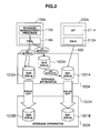
Fig. 2 is an explanatory diagram for copy control involving the logical volume Vol, which is not recognized by theOS 118A in themanagement computer 100A, in the storage apparatus 300 in the first embodiment of the invention. - The
storage apparatus 300A has threelogical volumes logical volumes more disk drives 1500. Thelogical volumes management computer 100A connected to thestorage apparatus 300A. The logical volume 1001A is recognized by thehost computer 200A connected to thestorage apparatus 300A. Note that, to prevent information leakage and data destruction, the logical volumes recognized by themanagement computer 100A and thehost computer 200A are not allowed to be recognized by other computers. Also, other host computers are not allowed to acquire the configuration information for the storage apparatus using an IP network. - Copy of the content in the
logical volumes 1001A and 1002A in thestorage apparatus 300A tological volumes storage apparatus 300B will be discussed here. In this copying, themanagement computer 100A needs to instruct the logical volumes recognized by themanagement computer 100A in thestorage apparatus 300A to start the copy from the logical volume 1001A to thelogical volume 1001 B and the copy from thelogical volume 1002A to thelogical volume 1002B. However, themanagement computer 100A does not recognize the logical volume 1001A, and so cannot create a copy control request for the logical volume 1001A. - Copying in this embodiment has the same meaning as copying, but may include the transfer of copy data to an arbitrary volume and storage of that data, depending on the description. Also, a logical volume Vol recognized by a host system (management computer 100 or host computer 200) means the logical volume Vol that can be identified by the OS in the host system and that can be operated directly by the host system for the reason that the
disk drive 1500, to which the logical volume Vol belongs, and the host system are physically or logically connected to each other. Meanwhile, a logical volume not Vol recognized by a host system (management computer 100 or host computer 200) means the logical volume Vol that cannot be identified by the OS in the host system and that cannot be operated directly by the host system for the reason that thedisk drive 1500, to which the logical volume Vol belongs, and the host system are not physically or logically connected to each other. - In light of the above, two means are combined to control an arbitrary logical volume Vol in this embodiment. First, regarding the first means, the management computer 100 acquires the information about the logical volume 1001A via the
logical volume 1003A (first volume) recognized by the management computer 100. Next, regarding the second means, the management computer 100 issues copy control requests directly to thelogical volumes logical volume 1003A recognized by the management computer 100 itself. Thelogical volume 1003A receives a command from the host system, and sets a command device (command volume) that enables transmission of a command to the unrecognized logical volume. - The above has been explained taking the case of high-level security for the storage apparatus 300 as an example. The method in this embodiment can also be utilized in, e.g., the case where the management computer 100 and the host computer 200 are in different platforms (mainframe system and open system).
-
Fig. 3 is a structural diagram of the storage information table 113 stored in the management computer 100. Processing for creating the storage information table 113 will be described below. - The storage information table 113 is a table showing information about the logical volumes Vol recognized by the management computer 100, and includes a
host group ID 11301, astorage apparatus ID 11302, a hardware (hereinafter, H/W)volume ID 11303, and anOS volume ID 11304. - The
host group ID 11301 is a recognized group identifier, which indicates storage information tables 113 acquired by the management computer 100 using the same condition. For example, all the storage information tables 113 in the storage apparatuses 300 directly accessible by the management computer 100 have the same host group IDs. - The
storage apparatus ID 11302 is an identifier for the storage apparatus 300 managed by the management computer 100. - The H/
W volume ID 11303 is an identifier that is used for internal processing in the storage apparatus 300 indicated by the storage apparatus ID 13002 and which the storage apparatus gives to the logical volume Vol to be managed in the storage apparatus 300. - The
OS volume ID 11304 is an identifier, which is assigned by the OS 118 in the management computer 100, for the logical volume Vol in the storage apparatus 300 indicated by thestorage apparatus ID 11302. -
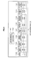
Fig. 4 is a structural diagram of the copy information table 114 stored in the management computer 100. A copy information table 114A is a table created after themanagement computer 100A acquires a storage information table 113A at the primary site, a storage information table 113B at the remote site, and a non-OS-recognized storage information table 116A, and will be described in detail below. - The copy information table 114 is a table created for each copy instruction issued by the management computer 100, and is given a copy group ID (copy group identifier) for each instruction.
- The copy information table 114 includes
copy information 11401, acopy status 11402, and copyconfiguration information 11403 to 11411. - The
copy information 11401 includes copy type and copy option information. The copy type indicates whether the copy as a function provided by the storage apparatus 300 is local copy or remote copy. Local copy means copying conducted in the same storage apparatus 300, and in this case, the copy source logical volume Vol and the copy destination logical volume Vol exist in the same storage apparatus 300. Remote copy means copying conducted between different storage apparatuses 300, and in this case, the copy source logical volume Vol and the copy destination logical volume Vol exist in thedifferent storage apparatuses - The copy option information is information indicating an option involved in each copy type. For example, the option information indicates whether writing to a secondary volume (copy destination logical volume Vol) is possible during suspension of local copy. Suspension of local copy means the suspension of local copy due to an instruction from the management computer 100.
- The
copy status 11402 shows the present status for copying managed by the copy information table 114. For example, thecopy status 11402 indicates which status the status for the copy managed by the copy information table 114 is from among a copy status, suspended status, pair status, and abnormal status. - The copy configuration information includes the
pair number 11403, primaryhost group ID 11404, secondaryhost group ID 11405, primarystorage apparatus ID 11406, primary H/W volume ID 11407, primaryOS volume ID 11408, secondarystorage apparatus ID 11409, secondary H/W volume ID 11410, and secondaryOS volume ID 11411. - The
pair number 11403 is a sequence number, and manages a copy order. - The primary
host group ID 11404 is an identifier that themanagement computer 100A processes as a copy source logical volume Vol (hereinafter, primary volume), and the primaryhost group ID 11404 registers thehost group ID 11301 in the storage information table 113. - The secondary
host group ID 11405 is an identifier that amanagement computer 100B processes as a copy destination logical volume Vol (hereinafter, secondary volume), and the secondaryhost group ID 11405 registers thehost group ID 11301 in the storage information table 113. - The primary
storage apparatus ID 11406 is an identifier for the storage apparatus on the primary side (hereinafter, primary storage apparatus) 300A that provides the copy source logical volume Vol. Theprimary storage apparatus 300A directly stores the data from thehost systems - The primary H/
W volume ID 11407 is an identifier that theprimary storage apparatus 300A gives to a primary volume to be managed in theprimary storage apparatus 300A. - The primary
OS volume ID 11408 is an identifier given to a primary volume to be managed by themanagement computer 100A. - The secondary
storage apparatus ID 11409 is an identifier for the storage apparatus on the secondary side (hereinafter, secondary storage apparatus) 300B that provides the copy destination secondary volume Vol. In local copying, the secondarystorage apparatus ID 11409 is the same as that for theprimary storage apparatus 300A. - The secondary H/
W volume ID 11410 is an identifier that thesecondary storage apparatus 300B gives to a secondary volume to be managed in thesecondary storage apparatus 300B. - The secondary
OS volume ID 11411 is a logical volume Vol identifier given to a secondary volume to be managed by themanagement computer 100B. -
Fig. 5 is a structural diagram of the local host group ID table 115 stored in the management computer 100. - The local host group ID table 115 stores a group identifier given to a group of logical volumes recognized by the management computer 100.
-
Fig. 6 is a structural diagram of the non-OS-recognized storage information table 116 stored in the management computer 100. Processing for creating the non-OS-recognized storage information table 116 will be described below. - The non-OS-recognized storage information table 116 is a table for managing the logical volumes Vol not recognized by the OS 118 in the management computer 100, and includes a
non-recognized flag 11601 not recognized by the OS 118, ahost group ID 11602, a basehost group ID 11603, astorage apparatus ID 11604, H/W volume IDs 11606, andOS volume IDs 11605. - The non-OS-recognized
flag 11601 is a flag that indicates whether or not the OS 118 in the management computer 100 recognizes the information about the storage apparatus 300 registered in the storage information table 113. - The
host group ID 11602 is a non-recognized group identifier, and is a group ID indicating a group of logical volumes not recognized by the OS 118 in the management computer 100. - The base
host group ID 11603 is a host group ID indicating the information about the storage apparatus 300 recognized by the OS 118 in the management computer 100. For example, all the storage information tables 113 for the storage apparatuses 300 directly accessible by the management computer 100 have the same host group IDs. - The
storage apparatus ID 11604 is an identifier for the storage apparatus 300 managed by the management computer 100. - The H/
W volume ID 11606 is an identifier for the logical volume Vol used in internal processing of the storage apparatus 300 indicated by thestorage apparatus ID 11604. - The
OS volume ID 11605 is a logical volume Vol identifier that is given to the logical volume Vol in the storage apparatus 300 indicated by thestorage apparatus ID 11604 and that is assigned by the OS 118 in the management computer 100. - With the non-OS-recognized storage information table 116, the volume IDs respectively managed by the storage apparatus 300 and the management computer 100 can be made to correspond to each other with respect to the same logical volume.
-
Fig. 7 is a structural diagram of the copypair management information 1210 stored in the storage apparatus 300 in the first embodiment of the invention. - The copy
pair management information 1210 includes alogical volume ID 12101,copy status information 12102, a copytarget storage ID 12103, a copytarget volume ID 12104, acopy pair ID 12105, agroup ID 12106, and acopy type 12107. - The
logical volume ID 12101 is an identifier for the logical volume provided by the storage apparatus 300 that stores the copypair management information 1210, and is an H/W volume ID. - The
copy status information 12102 shows the current status of copy with respect to the logical volume Vol identified by thelogical volume ID 12101. Specifically, thecopy status information 12102 shows which status the logical volume Vol identified by thelogical volume ID 12101 has from among a primary volume status, secondary volume status, copy status, suspended status, and abnormal status. - The copy
target storage ID 12103 is an identifier for the storage apparatus 300 that provides the logical volume Vol that forms a copy pair with the logical volume Vol identified by thelogical volume ID 12101. More specifically, the copytarget storage ID 12103 stores an identifier for thesecondary storage apparatus 300B. - The copy
target volume ID 12104 is an identifier for the logical volume Vol that forms a copy pair with the logical volume Vol identified by thelogical volume ID 12101. More specifically, the copytarget volume ID 12104 stores an identifier for the secondary volume serving as a copy destination for the data stored in the logical volume Vol identified by thelogical volume ID 12101. - The
copy pair ID 12105 is an identifier for a copy pair including the logical volume Vol identified by thelogical volume ID 12101 and the logical volume Vol identified by the copytarget volume ID 12104. Specifically, thecopy pair ID 12105 registers thepair number 11403 in the copy information table 114 that has been described with reference toFig. 4 . - The
copy group ID 12106 is an identifier for the copy group to which the copy pair identified by thecopy pair ID 12105 belongs. The storage apparatus 300 manages a copy group including one or more copy pairs. Therefore, the management computer 100 can specify a copy group to order the suspension, restart, or cancellation of local copy or remote copy collectively with respect to the copy pairs included in the copy group. - The
copy type 12107 is a type of copy executed on the copy pair identified by thecopy pair ID 12105. Specifically, thecopy type 12107 stores either local copy or remote copy. Note that remote copy is stored for thecopy type 12107 in this embodiment. -
Fig. 8 is a structural diagram of thevolume management information 1250 stored in the storage apparatus 300 in the first embodiment of the invention. - The
volume management information 1250 includes alogical volume ID 12501,volume status information 12502, acapacity 12503, acopy pair ID 12504, and agroup ID 12505. - The
logical volume ID 12501 is an identifier for the logical volume provided by the storage apparatus 300 that stores thevolume management information 1250, and is an H/W volume ID. - The
volume status information 12502 indicates the current status of the logical volume Vol identified by thelogical volume ID 12501. Specifically, thevolume status information 12502 stores at least one of "primary volume," "secondary volume," "normal," "abnormal," and "unloaded." - For example, when the logical volume Vol identified by the
logical volume ID 12501 is a primary volume, thevolume status information 12502 stores "primary volume." When the logical volume Vol identified by thelogical volume ID 12501 is a secondary volume, thevolume status information 12502 stores "secondary volume." - Also, when the host computer 200 can make normal access to the logical volume Vol identified by the
logical volume ID 12501, thevolume status information 12502 stores "normal." When the host computer 200 cannot make normal access to the logical volume Vol identified by thelogical volume ID 12501, thevolume status information 12502 stores "abnormal." For example, thevolume status information 12502 stores "abnormal" when there is a failure of thedisk drive 1500 or a copy fault. - When the logical volume Vol identified by the
logical volume ID 12501 has not stored data, thevolume status information 12502 stores "unloaded." - The
capacity 12503 is the capacity of the logical volume Vol identified by thelogical volume ID 12501. Thecopy pair ID 12504 is a unique identifier for a copy pair including the logical volume Vol identified by thelogical volume ID 12501. - The
copy pair ID 12504 is an identifier for the copy pair associated with thelogical volume ID 12501. Specifically, thecopy pair ID 12504 stores thepair number 11403 in the copy information table 114 that has been described with reference toFig. 4 . - The
group ID 12505 is an identifier for a copy group to which the copy pair with thecopy pair ID 12504 belongs. Thegroup ID 12505 stores the copy group ID given to the copy information table 114 created for each copy instruction issued by the management computer 100. -
Fig. 9 is an explanatory diagram for an I/O request 7300 in the first embodiment of the invention. - The I/
O request 7300 is issued by the management computer 100 or the host computer 200. Also, the I/O request 7300 includes adestination 73001,instruction content 73002, a control target H/W volume ID 73003, agroup ID 73004, and anoption 73005. - The
destination 73001 stores an identifier for the storage apparatus 300 and an identifier for the H/W volume that serves as a transmission destination for the I/O request 7300. For example, when the I/O request 7300 is transmitted to the logical volume Vol directly recognized by the management computer 100 or the host computer 200, the identifier for the directly recognized logical volume Vol is stored as an identifier for the H/W volume. When the I/O request 7300 is transmitted to the logical volume Vol not directly recognized by the management computer 100 or the host computer 200, an identifier for a command device is stored as an identifier for the H/W volume. - The
instruction content 73002 is the content of processing ordered by the I/O request 7300. Theinstruction content 73002 is an instruction for remote copy control, an instruction for data access, etc. Specifically, theinstruction content 73002 is a write request, a read request, or a copy control request. Moreover, examples of copy control requests include requests for remote copy start, remote copy suspension, remote copy restart, remote copy cancellation, local copy start, local copy suspension, local copy restart, local copy cancellation, and status acquisition. - The control target H/
W volume ID 73003 is an identifier for a target logical volume Vol processed by the storage apparatus 300 based on the instruction content in the I/O request 7300. More specifically, the storage apparatus 300 executes processing for the instruction content with respect to the control target H/W volume ID 73003 included in the received I/O request 7300. - When the I/
O request 7300 is transmitted to the logical volume Vol not directly recognized by the management computer 100 or the host computer 200, the control target H/W volume ID 73003 stores an identifier for the unrecognized logical volume Vol. - The
group ID 73004 is an identifier for a copy group that serves as a target for the processing based on the I/O request 7300. Thegroup ID 73004 stores the copy group ID given to the copy information table 114 created for each copy instruction issued by the management computer 100. - The
option 73005 stores copy configuration information, option information that supports the I/O request 7300, data requested to be written in accordance with the I/O request, etc. Note that the copy configuration information includes, e.g., a copy type, a copy destination storage ID, a copy destination logical volume ID, a copy source storage ID, and a copy source logical volume ID, - Next, processing for creating the storage information table 113 will be described. The processing for creating the storage information table 113 is executed by a
processor 120A in themanagement computer 100A in accordance with astorage management program 112A. -
Fig. 10 is a flowchart for the creation, which is conducted by themanagement computer 100A, of the storage information table 113A concerning thestorage apparatus 300A in the primary site. - The
management computer 100A acquires, from anOS 118A, the management information for the logical volume Vol set via the input by a user (step 5000). The management information for the logical volume Vol input by a user includes a device number, a drive letter, a device file, etc. Themanagement computer 100A acquires the information (storage system ID, H/W volume ID) about thestorage apparatus 300A managed by theOS 118A via an operation interface of theOS 118A. When the information about thestorage apparatus 300A acquired from theOS 118A is insufficient as information about the storage information table 113A, themanagement computer 100A may acquire more information from thestorage apparatus 300A using an I/O request. - Then, the
management computer 100A registers the information obtained in step 5000 as storage information in the storage information table 113A to create the storage information table 113A (step 5010). The storage information obtained in step 5000 is information including a host group ID, a storage apparatus ID, H/W volume IDs, and OS volume IDs. For the host group ID in the storage information table 113A, the ID previously registered in a local host group ID table 115A in themanagement computer 100A is registered. - Next, the
management computer 100A executes processing for creating the non-OS-recognized storage information table 116A (non-recognized volume creation unit). - The flow described below is one for creating the non-OS-recognized storage information table 116A, but is also executed for creating the storage information table 113A concerning the
storage apparatus 300B in the remote site. - The processing for creating the non-OS-recognized storage information table 116A or the storage information table 113A for the
storage apparatus 300B is executed by theprocessor 120A in themanagement computer 100A in accordance with thestorage management program 112A. -
Fig. 11 shows a flow for creation, which is performed by themanagement computer 100A, of the non-OS-recognized storage information table 116A or the storage information table 113A for thestorage apparatus 300B in the remote site. - For the assumptions for the management computer 100 to determine an unrecognized logical volume Vol, a user inputs a host group ID, a storage apparatus ID, and an H/W volume ID to the
management computer 100A. Themanagement computer 100A acquires the input information (step 5100). For the host group ID, an ID different from the local host group ID previously set in themanagement computer 100A is set. The H/W volume ID specifies an H/W volume ID(s) in an arbitrary range output in the screen of themanagement computer 100A regardless of whether the relevant volume is a recognized logical volume or an unrecognized logical volume. - It is assumed that the host group ID, the storage apparatus ID, and the H/W volume ID input by a user in step 5100 are respectively referred to as input host group ID, input storage apparatus ID, and input H/W volume ID.
- Next, the
management computer 100A reads, frommemory 110A, the storage information table 113A including the local host group ID, which is previously registered in themanagement computer 100A, corresponding to the input storage apparatus ID obtained in step 5100 (step 5105). - Then, the
management computer 100A judges whether the input H/W volume ID has been registered in the read storage information table 113A (step 5110). - If it is determined that the input H/W volume ID has been registered in the storage information table 113A as a result of the judgment in step 5110 (step 5110: Yes), the
management computer 100A judges whether the next input H/W volume ID exists because the above input H/W volume ID as a judgment target indicates the logical volume Vol recognized by themanagement computer 100A (step 5180). At this point, the volume information that themanagement computer 100A selects next from the storage information table 113A may be selected in a fixed order or a random order. - Meanwhile, if it is determined that the input H/W volume ID has not been registered in the storage information table 113A as a result of the judgment in step 5110 (step 5110: No), the input H/W volume ID serving as a judgment target is the logical volume Vol not recognized by the
management computer 100A. Therefore, themanagement computer 100A sets the content of the I/O request 7300 (step 5120). - Specifically, the
management computer 100A acquires thestorage apparatus ID 11302 and arbitrary volume information (logical volume Vol information consisting of the H/W volume ID 11303 and the OS volume ID 11304) from the storage information table 113A. Themanagement computer 100A sets the storage apparatus ID and the H/W volume ID in the acquired information as thedestination 73001 of the I/O request 7300. - Also, the
management computer 100A sets "copy control request (status acquisition)" for theinstruction content 73002 in the I/O request 7300, and set the input H/W volume ID for the control target H/W volume ID 73003. - The
management computer 100A then issues the I/O request 7300 to thestorage apparatus 300A, and waits for a response to the I/O request 7300 (step 5130). - Next, when the
management computer 100A receives the response to the I/O request 7300 from thestorage apparatus 300A, themanagement computer 100A judges whether or not the response to the I/O request 7300 is normal (step 5140). - If the response to the I/
O request 7300 is normal (step 5140: Yes), this indicates the existence of the unrecognized logical volume Vol as a control target for the I/O request 7300. - Then, the
management computer 100A searches for the non-OS-recognized storage information table 116A in which thehost group ID 11602 is the input host group ID, the basehost group ID 11603 is the local host group ID, and thestorage apparatus ID 11604 is the input storage apparatus ID in thememory 110A (step 5150). - If it is determined that the storage information not recognized by the
OS 118A does not exist in the non-OS-recognized storage information table 116A as a result of the judgment in step 5150 (step 5150: No), themanagement computer 100A creates the non-OS-recognized volume information table 116A in which thehost group ID 11602 is the input host group ID, the basehost group ID 11603 is the local host group ID, and thestorage apparatus ID 11604 is the input storage apparatus ID (step 5160). - If it is determined that the storage information not recognized by the
OS 118A exists in the non-OS-recognized storage information table 116A as a result of the judgment in step 5150 (step 5150: Yes), themanagement computer 100A adds volume information to the non-OS-recognized storage information table 116A (step 5170). Regarding the content of the volume information, the input H/W volume ID is additionally stored for the H/W volume ID 11606, and an arbitrary OS volume ID is additionally stored for theOS volume ID 11605. - Note that an arbitrary OS volume ID added for the
OS volume ID 11605 needs to be distinguishable for a user. This can be realized, e.g., by the management computer 100 displaying the list of OS volume IDs and H/W volume IDs on the screen instep 5170, or by enabling a user to set an arbitrary value for the OS volume ID. - Finally, the
management computer 100A judges whether or not a further input H/W volume ID exists. If a further H/W volume ID exists (step 5180: No), the processing from steps 5110 through 5170 will be repeated. If the H/W volume ID does not exist (step 5180: Yes), themanagement computer 100A terminates this processing. - As described above, the volumes not recognized by the
management computer 100A can be found from the H/W volume IDs in an arbitrary range output in the screen of themanagement computer 100A. - Next, processing for creating the storage information table 113B in the remote site will be described. The storage information table 113B at the remote site is created by the
management computer 100A in the primary site in accordance with thestorage management program 112A or by themanagement computer 100B in the remote site. - When the
management computer 100B in the remote site creates the storage information table 113B, storage information is acquired based on the same processing procedure as for the flow inFig. 10 , or the content of the storage information table 113B created in themanagement computer 100A is subjected to copy. Regarding the copy method, FTP, etc. via a network or a portable storage medium (USB memory or similar) may be employed. When this is not permitted in terms of security policy, themanagement computer 100A in the primary site creates the storage information table 113B as described below. - A method for the creation, which is conducted by the
management computer 100A in the primary site, of the storage information table 113B will be described with reference toFig.11 . - When the
management computer 100A acquires the storage information table 113B concerning thestorage apparatus 300B in the remote site in the processing ofFig. 11 , themanagement computer 100A creates the I/O request 7300 employing a remote transfer request in step 5120. Employing the remote transfer request enables the I/O request 7300 to be transferred to thestorage apparatus 300B in the remote site via thestorage apparatus 300A. - Here,
Fig. 12 shows a configuration example of the I/O request 7300 when using a remote transfer request. When the remote transfer request is used, themanagement computer 100A couples the I/O request 7300A and an I/O request 7300B to each other. - The
management computer 100A sets thestorage apparatus ID 11302 registered in the storage information table 113B and an arbitrary H/W volume ID in the same table for adestination 73001A in I/O request 1 (7300A). Themanagement computer 100A sets a remote request (remote transfer) forinstruction content 73002A, and sets an identifier for the command device in thestorage apparatus 300A for a control target H/W volume ID 73003A. Themanagement computer 100A also sets a copy group ID given to the copy information table 114A for agroup ID 73004A, and sets a pointer for I/O request 2 (7300B) for anoption 73005A. - Subsequently, regarding I/O request 2 (7300B), the
management computer 100A sets the storage apparatus ID at the remote site and the H/W volume ID at the remote site for adestination 73001 B, sets a copy control request (status acquisition) forinstruction content 73002B, and sets the input H/W volume ID for a control target H/W volume ID 73003B. Themanagement computer 100A executes the same processing procedure as in the flowchart inFig. 11 except the point that the information about thestorage apparatus 300B in the remote site is acquired using the remote transfer request. -
Fig. 13 shows a flow for creation, which is conducted by themanagement computer 100A, of the copy information table 114A. Themanagement computer 100A creates the copy information table 114A in accordance with thestorage management program 112A. Themanagement computer 100A acquires the storage information table 113A at the primary site, the storage information table 113B at the remote site, and the non-OS-recognized storage information table 116A, and then creates the copy information table 114A. - A user inputs, via the screen of the
management computer 100A, a copy source host group ID (referred to as primary host group ID), a copy destination host group ID (referred to as secondary host group ID), and a copy type (step 5200). Examples of copy types include local copy and remote copy. - After the input, the
management computer 100A displays the storage apparatus IDs 13002 in all the storage information tables 113A, in which the host group ID corresponding to the primary host group ID has been registered, to indicate copy source primary storage apparatuses, and displays the storage apparatus IDs 13002 in all the storage information tables 113A, in which the host group ID corresponding to the secondary host group ID has been registered, to indicate copy destination secondary storage apparatuses (step 5210). - A user selects an arbitrary copy source primary storage apparatus and an arbitrary copy destination secondary storage apparatus from among the plural copy source primary storage apparatuses and copy destination secondary storage apparatuses displayed in step 5210 (step 5220).
- Then, the
management computer 100A refers to the storage information tables 113A in which the storage apparatus ID for the storage apparatus selected above has been registered, and displays the lists of OS volume IDs for the copy source primary storage apparatus and copy destination secondary storage apparatus (step 5230). - At this point, the
management computer 100A confirms the presence or absence of the copy information table 114A corresponding to thememory 110A (step 5235). - If the copy information table 114A does not exist (step 5235: No), the
management computer 100A creates the copy information table 114A based on the storage information table 113A (step 5240). - Next, a user selects a copy source OS volume ID and a copy destination OS volume ID via the screen of the
management computer 100A so that themanagement computer 100A defines a copy pair. Themanagement computer 100A adds the selected OS volume ID to the copy information table 114A (step 5245). - The
management computer 100A confirms with a user regarding the presence or absence of a copy pair to be added (combination of primary and secondary volumes respectively serving as a copy source and a copy destination). If the copy pair addition needs to be conducted (step 5250: Yes), themanagement computer 100A executes processing again starting fromstep 5230. - Next, the
management computer 100A checks the change of a host group ID (step 5255). If themanagement computer 100A changes the host group ID (step 5255: Yes), themanagement computer 100A returns to step 5200; meanwhile, if themanagement computer 100A does not change the host group ID (step 5255: No), themanagement computer 100A terminates this processing. - As described above, the
management computer 100A can create a copy group by changing the host group ID even when the storage apparatus 300 has both the logical volumes Vol recognized by the OS 118 and the logical volumes Vol not recognized by the OS 118 together. The copy group indicates a set of plural copies, and themanagement computer 100A can perform collective copy operation by using the copy group. The copy group is given the above-mentioned copy group ID (copy group identifier). -
Fig. 14 is a flowchart for creating an I/O request for copy control processing executed by themanagement computer 100A in the first embodiment. Themanagement computer 100A creates the I/O request in accordance with thestorage management program 112A. - When a user specifies the copy information table 114A and specifies a copy control instruction, the
management computer 100A refers to arbitrary column data in the copy configuration information (information group of 11403 to 11411) in the copy information table 114A (step 5300). - The
management computer 100A compares the primaryhost group ID 11404 in the column data to the local host group ID in the local host group ID table 115A (step 5310). - If the compared IDs correspond to each other as a result of step 5310 (step 5310: Yes), copy control is performed for the logical volume Vol recognized by the
management computer 100A. Therefore, themanagement computer 100A registers the primarystorage apparatus ID 11406 and the primary H/W volume ID 11407 in the above column data for thedestination 73001 in the I/O request 7300, and registers the primary H/W volume ID 11407 in the column data also for the control target H/W volume ID 73003 in the I/O request 7300. For theinstruction content 73002, thegroup ID 73004, and theoption 73005 in the I/O request 7300, what is specified by a user is registered. Themanagement computer 100A issues the resultant I/O request 7300 to thestorage apparatus 300A (step 5320). - Meanwhile, if the compared IDs do not correspond to each other as a result of step 5310 (step 5310: No), copy control is performed for the logical volume Vol not recognized by the
management computer 100A. Themanagement computer 100A registers the primarystorage apparatus ID 11406 in the column data and an arbitrary H/W volume ID 11303 registered in the storage information table 113A for thedestination 73001 in the I/O request 7300, and sets the primary H/W volume ID 11407 in the column data for the control target H/W volume ID 73003. For theinstruction content 73002, thegroup ID 73004, and theoption 73005 in the I/O request 7300, what is specified by a user is registered. Themanagement computer 100A issues the resultant I/O request 7300 to thestorage apparatus 300A (step 5330). - Subsequently, the
management computer 100A judges whether or not control target column data other than the column data referred to instep 5300 has been registered in the copy information table 114A (step 5340). If the column data has been registered (step 5340: Yes), themanagement computer 100A repeats this processing again starting fromstep 5300. - Meanwhile, if the column data has not been registered (step 5340: No), the
management computer 100A terminates this processing. - Next, the processing executed by the
primary storage apparatus 300A that has received the I/O request 7003 from themanagement computer 100A after the creation of the I/O request 7300 by themanagement computer 100A and the following processing executed by thesecondary storage apparatus 300B will be described. -
Fig. 15 is a flowchart of initial copy processing executed by the primary and secondary storage apparatuses 300. The initial copy processing is processing for having primary volume data conform to secondary volume data. This processing is executed by the primary and secondary storage apparatuses 300 in accordance with the copy process programs 1230 and the input/output process programs 1290. - When an I/
O controller 1300A in theprimary storage apparatus 300A receives the I/O request 7300 that orders the start of remote copy, theprimary storage apparatus 300A starts initial copy processing. - The I/
O controller 1300A in theprimary storage apparatus 300A creates copypair management information 1210A based on the copy configuration information extracted from the received I/O request 7300 (step 7010). - Specifically, the I/
O controller 1300A in theprimary storage apparatus 300A stores the H/W volume ID 73003A in the I/O request 7300A, which serves to indicate a copy source primary volume, for thelogical volume ID 12101 in the copypair management information 1210. The I/O controller 1300A in theprimary storage apparatus 300A then stores "initial copy" for thecopy status information 12102 in the copypair management information 1210. - Also, the I/
O controller 1300A in theprimary storage apparatus 300A stores the copy destination storage apparatus ID in thedestination 73001 B for the copytarget storage ID 12103 in the copypair management information 1210. The I/O controller 1300A in theprimary storage apparatus 300A then stores the copy destination H/W volume ID 73003B in the I/O request 7300B for the copytarget volume ID 12104 in the copypair management information 1210. At this point, the I/O controller 1300A specifies the control target H/W volume ID 73003A in the I/O request 7300A as a command device. - Moreover, the I/
O controller 1300A in theprimary storage apparatus 300A stores the pair number obtained from theoption 73005A in the I/O request 7300A for thecopy pair ID 12105. The I/O controller 1300A in theprimary storage apparatus 300A stores thegroup ID 73004 acquired from the I/O request 7300 for thegroup ID 12106. The I/O controller 1300A in theprimary storage apparatus 300A then stores the copy type included in the extracted copy configuration information for thecopy type 12107 in the copypair management information 1210. - Subsequently, the I/
O controller 1300A in theprimary storage apparatus 300A instructs adisk controller 1400A in theprimary storage apparatus 300A to start initial copy processing (step 7020). - Then, the
disk controller 1400A in theprimary storage apparatus 300A reads data from the primary volume identified by thelogical volume ID 12101 in the copypair management information 1210A. Thedisk controller 1400A in theprimary storage apparatus 300A stores the read data in thecache memory 1100A (step 7030). - Moreover, the
disk controller 1400A in theprimary storage apparatus 300A notifies the I/O controller 1300A in theprimary storage apparatus 300A of the address for the block from which the data has been read, the data length of the read data, and the address in the cache memory in which the data has been stored (step 7030). - Then, the I/
O controller 1300A in theprimary storage apparatus 300A creates adata transfer frame 1240 based on the information given from thedisk controller 1400A in theprimary storage apparatus 300A and the copypair management information 1210A.Fig. 16 shows an example of thedata transfer frame 1240. - Specifically, the I/
O controller 1300A in theprimary storage apparatus 300A stores the copytarget volume ID 12104 in the copypair management information 1210A for alogical volume ID 12401 in thedata transfer frame 1240. The I/O controller 1300A in theprimary storage apparatus 300A then stores the block address given from thedisk controller 1400A for ablock address 12402 in thedata transfer frame 1240. - Next, the I/
O controller 1300A in theprimary storage apparatus 300A stores the data length given from thedisk controller 1400A forwrite data length 12403 in thedata transfer frame 1240. The I/O controller 1300A in theprimary storage apparatus 300A stores part or all of the data stored in thecache memory 1100A fortransfer data 12404 in thedata transfer frame 1240. Also, only during the first transfer, the I/O controller 1300A stores thevolume management information 1250 for thetransfer data 12404. - The I/
O controller 1300A in theprimary storage apparatus 300A then stores, for aserial number 12405 in thedata transfer frame 1240, the order in which thedata transfer frame 1240 is created in initial copy. Moreover, the I/O controller 1300A in theprimary storage apparatus 300A stores the copytarget storage ID 12103 in the copypair management information 1210 for a transferdestination storage ID 12406 in thedata transfer frame 1240. - The I/
O controller 1300A in theprimary storage apparatus 300A then transmits the createddata transfer frame 1240 to the copy destinationsecondary storage apparatus 300B (step 7040). - An I/
O controller 1300B in thesecondary storage apparatus 300B receives thedata transfer frame 1240. The I/O controller 1300B in thesecondary storage apparatus 300B then creates copypair management information 1210B based on the receiveddata transfer frame 1240, etc. (step 7050). - Specifically, the I/
O controller 1300B in thesecondary storage apparatus 300B stores thelogical volume ID 12401 in the receiveddata transfer frame 1240 for thelogical volume ID 12101 in the copypair management information 1210B. Then, the I/O controller 1300B in thesecondary storage apparatus 300B stores "initial copy" for thecopy status information 12102 in the copypair management information 1210B. - Subsequently, the I/
O controller 1300B in thesecondary storage apparatus 300B stores, for the copytarget storage ID 12103 in the copypair management information 1210B, the identifier for theprimary storage apparatus 300A as the transmission source for the receiveddata transfer frame 1240. The I/O controller 1300B in thesecondary storage apparatus 300B then stores, for the copytarget volume ID 12104 in the copypair management information 1210B, the identifier for the primary volume where thetransfer data 12404 in thedata transfer frame 1240 has been stored. - Then, the I/
O controller 1300B in thesecondary storage apparatus 300B stores "remote copy" for thecopy type 12107 in the copypair management information 1210B. - The I/
O controller 1300B in thesecondary storage apparatus 300B writes thetransfer data 12404 in thedata transfer frame 1240 to the secondary volume identified by thelogical volume ID 12401 in the data transfer frame 1240 (step 7060). - The
primary storage apparatus 300A and thesecondary storage apparatus 300B repeatedly execute steps 7030 through 7060. As a result, all the data in the primary volume is stored in the secondary volume. - The
primary storage apparatus 300A and thesecondary storage apparatus 300B then terminate initial copy processing. After theprimary storage apparatus 300A terminates initial copy, theprimary storage apparatus 300A stores "primary volume" for thecopy status information 12102 in the copypair management information 1210A. Also, thesecondary storage apparatus 300B stores "secondary volume" in thecopy status information 12102 in the copypair management information 1210B. -
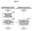
Fig. 17 is a flowchart of differential copy processing executed by the storage apparatus 300 in the first embodiment of the invention. - After the termination of initial copy processing, the primary and secondary storage apparatuses 300 start operation of differential copy. More specifically, the primary and secondary storage apparatuses 300 start operation of differential copy after the data in the primary volume and the data in the secondary volume conform to each other.
- Specifically, upon receiving a write request after the termination of initial copy processing, the
primary storage apparatus 300A executes differential copy processing. For example, theprimary storage apparatus 300A writes data in the primary volume, and writes the write data in the secondary volume accordingly. - The
primary storage apparatus 300A receives the I/O request 7300. The I/O request 7300 is a write request. Theprimary storage apparatus 300A extracts the data requested to be written (write data) from theoption 73005 in the I/O request 7300. Theprimary storage apparatus 300A extracts the storage apparatus ID and H/W volume ID from thedestination 73001 in the I/O request 7300. - Then, the
primary storage apparatus 300A writes the extracted write data to the logical volume Vol identified by the acquired logical volume ID. - The
primary storage apparatus 300A creates the data transfer frame 1240 (step 7250). - Specifically, the copy source
primary storage apparatus 300A selects the copypair management information 1210A including thelogical volume ID 12101 corresponding to the acquired logical volume ID. The copy sourceprimary storage apparatus 300A then extracts the copytarget storage ID 12103 and the copytarget volume ID 12104 from the selected copypair management information 1210A. - Next, the
primary storage apparatus 300A stores the extracted copytarget volume ID 12104 for thelogical volume ID 12401 in thedata transfer frame 1240. Theprimary storage apparatus 300A then stores, for theblock address 12402 in thedata transfer frame 1240, the address for the block in which the write data has been stored. - Subsequently, the
primary storage apparatus 300A stores the size of the write data for thewrite data length 12403 in thedata transfer frame 1240. Theprimary storage apparatus 300A then stores part or all of the write data for thetransfer data 12404 in thedata transfer frame 1240. - The
primary storage apparatus 300A stores, for theserial number 12405 in thedata transfer frame 1240, the order in which thetransfer frame 1240 is created in differential copy. Theprimary storage apparatus 300A stores the extracted copytarget storage ID 12103 for the transferdestination storage ID 12406 in thedata transfer frame 1240. - Next, the
primary storage apparatus 300A transmits the createddata transfer frame 1240 to thesecondary storage apparatus 300B (step 7260). - The
secondary storage apparatus 300B receives thedata transfer frame 1240. Then, thesecondary storage apparatus 300B writes thetransfer data 12404 in thedata transfer frame 1240 to the logical volume Vol identified by thelogical volume ID 12401 in the data transfer frame 1240 (step 7270). - The storage apparatuses 300 terminate differential copy processing with respect to one I/O request.
- According to this embodiment, remote copy can be achieved with respect to all the volumes that are both recognized and not recognized by the management computer that makes the copy request. I particular, copy can be conducted with respect to the volumes, in the primary storage apparatus and secondary storage apparatus, which are both recognized and not recognized by the management computer.
- Also, according to this embodiment, high security can be achieved with a storage system employing an in-band system.
- A second embodiment of the invention will be described with reference to figures.
-
Fig. 18 is a block diagram of a configuration for a storage system 1' in a second embodiment of the invention. As shown inFig. 18 , the management computer 100, the host computer 200, and the storage apparatus 300 are connected to one another via thedata communication line 500 in one site in the second embodiment. Also, the I/O transmission/reception unit 1320 in the storage apparatus 300 is connected to atape device 400 via a network (not shown in the figure) for copy. Among the components, the management computer 100, the host computer 200, and the storage apparatus 300 are the same as themanagement computer 100A, thehost computer 200A, and thestorage apparatus 300A in the first embodiment. Also, thetape device 400 hasplural tapes 4000 that provide physical volumes for storing data. -
Fig. 19 shows the outline of the configuration for the storage system 1' in the second embodiment of the invention. The logical volumes Vol recognized by the management computer 100 are thelogical volumes logical volume 1001. Thelogical volume 1003 is a command device. The configuration for the storage apparatus 300 is the same as for thestorage apparatus 300A that has been described in the first embodiment. - In the second embodiment, local copy is conducted between the logical volumes Vol in the storage apparatus 300, and the management computer 100 conducts backup with the tape. With the copy source primary
logical volume 1001, which serves as the volume not recognized by the management computer 100, and the copy destination secondarylogical volume 1002, which serves as the volume recognized by the management computer 100, copy control can be performed by the same method as in the first embodiment except the point that an I/O request that orders local copy is used. After the termination of the local copy between the volumes, the storage apparatus 300 further copies the copy data in the copy destinationsecondary volume 1002 to thetapes 4000. - According to this embodiment, local copy can be achieved with respect to all the volumes that are both recognized and not recognized by the management computer that makes the copy request. In particular, copy can be conducted with respect to the volumes, in the storage apparatus, which are both recognized and not recognized by the management computer.
- Also, according to this embodiment, high security can be achieved with a storage system employing an in-band system.
- The volumes that are recognized and not recognized by the management computer have been described in the first and second embodiments. However, copy control can be achieved with the above-described procedure also regarding the volumes that are recognized and not recognized by the host computer.
- While the invention has been described with respect to a limited number of embodiments, those skilled in the art, having benefit of this disclosure, will appreciate that other embodiments can be devised which do not depart from the scope of the invention as disclosed herein. Accordingly, the scope of the invention should be limited only by the attached claims.
Claims (12)
- A storage system in which a management computer and a host computer are connected to one or more storage apparatuses via a data communication line, wherein:
the one or more storage apparatuses provide the management computer with at least one first volume for storing data from the management computer, provide the host computer with at least one second volume for storing data from the host computer, and manage a volume address for the one or more storage apparatuses to manage the first volume and the second volume in the one or more storage apparatuses; and
the management computer issues a command specifying an arbitrary volume address to the one or more storage apparatuses, and designates, when receiving a normal response from the arbitrary volume address, a volume with the arbitrary volume address as the second volume. - The storage system according to claim 1, wherein:
the one or more storage apparatuses provide two or more of the first volumes, and have, among the first volumes, a command volume that assigns the command specifying the arbitrary volume address to the second volume; and
the management computer issues the command specifying the arbitrary volume address to the command volume when the second volume serves as a copy source target, and issues the command specifying the arbitrary volume address to the first volume when the first volume serves as a copy source target. - The storage system according to claim 1, wherein:the one or more storage apparatuses provide two or more of the first volumes and two or more of the second volumes; give a first group identifier to the first volumes that form a first volume group; give a second group identifier to the second volumes that form a second volume group; determine a copy source primary group identifier and a copy destination secondary group identifier based on the first group identifier and the second group identifier to set one or more pairs, and give a copy group identifier to the one or more pairs to manage the one or more pairs; and create the command specifying the arbitrary volume address based on a pair that belongs to an arbitrary copy group.
- The storage system according to claim 3, wherein:the one or more storage apparatuses are given an apparatus identifier, and manage the apparatus identifier with the first group identifier and the second group identifier.
- The storage system according to claim 3, wherein the first volume group and the second volume group are provided in one storage apparatus.
- The storage system according to claim 1, wherein:the one or more storage apparatuses are connected to a tape device; andthe tape device provides a third volume that stores copy data for the data stored in the first volume and the second volume.
- A copy method for a storage system in which a management computer and a host computer are connected to one or more storage apparatuses via a data communication line, the method comprising:under the control of the one or more storage apparatuses, providing the management computer with at least first volume for storing data from the management computer, providing the host computer with at least second volume for storing data from the host computer, and managing a volume address for the one or more storage apparatuses to manage the first volume and the second volume in the one or more storage apparatus; andunder the control of the management computer, issuing a command specifying an arbitrary volume address to the one or more storage apparatuses, and designating, when receiving a normal response from the arbitrary volume address, a volume with the arbitrary volume address as the second volume.
- The copy method according to claim 7, comprising:under the control of the one or more storage apparatuses, providing two or more of the first volumes, and setting, among the first volumes, a command volume that assigns the command specifying the arbitrary volume address to the second volume; andunder the control of the management computer, issuing the command specifying the arbitrary volume address to the command volume when the second volume serves as a copy source target, and issuing the command specifying the arbitrary volume address to the first volume when the first volume serves as a copy source target.
- The copy method according to claim 7, comprising, under the control of the one or more storage apparatuses:providing two or more of the first volumes and two or more of the second volumes;giving a first group identifier to the first volumes that form a first volume group;giving a second group identifier to the second volumes that form a second volume group;determining a copy source primary group identifier and a copy destination secondary group identifier based on the first group identifier and the second group identifier to set one or more pairs, and giving a copy group identifier to the one or more pairs to manage the one or more pairs; andcreating the command specifying the arbitrary volume address based on a pair that belongs to an arbitrary copy group.
- The copy method according to claim 9, comprising, under the control of the one or more storage apparatuses, being given an apparatus identifier, and managing the apparatus identifier with the first group identifier and the second group identifier.
- The copy method according to claim 9, comprising providing the first volume group and the second volume group in one storage apparatus.
- The copy method according to claim 7, in which the one or more storage apparatuses are connected to a tape device, comprising, under the control of the tape device, providing a third volume that stores copy data for the data stored in the first volume and the second volume.
Applications Claiming Priority (1)
| Application Number | Priority Date | Filing Date | Title |
|---|---|---|---|
| JP2008039601A JP5401041B2 (en) | 2008-02-21 | 2008-02-21 | Storage system and copy method |
Publications (3)
| Publication Number | Publication Date |
|---|---|
| EP2093655A2 true EP2093655A2 (en) | 2009-08-26 |
| EP2093655A3 EP2093655A3 (en) | 2011-02-09 |
| EP2093655B1 EP2093655B1 (en) | 2017-04-12 |
Family
ID=40636984
Family Applications (1)
| Application Number | Title | Priority Date | Filing Date |
|---|---|---|---|
| EP08171173.1A Active EP2093655B1 (en) | 2008-02-21 | 2008-12-10 | Storage system and copy method |
Country Status (3)
| Country | Link |
|---|---|
| US (2) | US8010761B2 (en) |
| EP (1) | EP2093655B1 (en) |
| JP (1) | JP5401041B2 (en) |
Families Citing this family (3)
| Publication number | Priority date | Publication date | Assignee | Title |
|---|---|---|---|---|
| US8433866B2 (en) | 2009-10-23 | 2013-04-30 | Hitachi, Ltd. | Remote copy system and remote copy control method in which a copy pair is changed from a first consistency group to a second consistency group (STG) |
| JP2014191399A (en) * | 2013-03-26 | 2014-10-06 | Fujitsu Ltd | Information processing system, storage device, and backup method |
| US20160253114A1 (en) * | 2013-11-14 | 2016-09-01 | Hitachi, Ltd. | Method and apparatus for optimizing data storage in heterogeneous environment |
Citations (3)
| Publication number | Priority date | Publication date | Assignee | Title |
|---|---|---|---|---|
| JPH1185408A (en) | 1997-09-12 | 1999-03-30 | Hitachi Ltd | Storage control device |
| JP2005196618A (en) | 2004-01-09 | 2005-07-21 | Hitachi Ltd | Storage device and its control method |
| JP2007102455A (en) | 2005-10-04 | 2007-04-19 | Hitachi Ltd | Storage system and configuration change method |
Family Cites Families (15)
| Publication number | Priority date | Publication date | Assignee | Title |
|---|---|---|---|---|
| JP2003202964A (en) * | 2002-01-09 | 2003-07-18 | Hitachi Ltd | Method for controlling computer system, computer system, method for controlling storage device and storage device |
| JP4612373B2 (en) | 2004-09-13 | 2011-01-12 | 株式会社日立製作所 | Storage device and information system using the storage device |
| US7434091B1 (en) * | 2004-12-07 | 2008-10-07 | Symantec Operating Corporation | Flexibly combining mirroring, concatenation and striping in virtual storage devices |
| JP2006309483A (en) * | 2005-04-28 | 2006-11-09 | Hitachi Ltd | Storage device and storage system |
| US7840755B2 (en) * | 2005-05-24 | 2010-11-23 | Lsi Corporation | Methods and systems for automatically identifying a modification to a storage array |
| US20060277225A1 (en) * | 2005-06-07 | 2006-12-07 | Mark Timothy W | Converting file system metadata structure while the file system remains available |
| JP2007058728A (en) * | 2005-08-26 | 2007-03-08 | Hitachi Ltd | Data transfer system |
| US20070300033A1 (en) * | 2006-06-21 | 2007-12-27 | Hitachi, Ltd. | System and method for reconfiguring continuous data protection system upon volume size change |
| JP4902289B2 (en) * | 2006-07-31 | 2012-03-21 | 株式会社日立製作所 | Backup system and backup method |
| JP4942418B2 (en) * | 2006-08-04 | 2012-05-30 | 株式会社日立製作所 | Computer system and snapshot creation method thereof |
| JP4890160B2 (en) * | 2006-09-06 | 2012-03-07 | 株式会社日立製作所 | Storage system and backup / recovery method |
| JP5057366B2 (en) * | 2006-10-30 | 2012-10-24 | 株式会社日立製作所 | Information system and information system data transfer method |
| JP5244332B2 (en) * | 2006-10-30 | 2013-07-24 | 株式会社日立製作所 | Information system, data transfer method, and data protection method |
| JP5090022B2 (en) * | 2007-03-12 | 2012-12-05 | 株式会社日立製作所 | Computer system, access control method, and management computer |
| JP2008287405A (en) * | 2007-05-16 | 2008-11-27 | Hitachi Ltd | Path management method, host computer, and path management program |
-
2008
- 2008-02-21 JP JP2008039601A patent/JP5401041B2/en not_active Expired - Fee Related
- 2008-04-23 US US12/107,994 patent/US8010761B2/en not_active Expired - Fee Related
- 2008-12-10 EP EP08171173.1A patent/EP2093655B1/en active Active
-
2011
- 2011-08-23 US US13/215,622 patent/US8214613B2/en active Active
Patent Citations (3)
| Publication number | Priority date | Publication date | Assignee | Title |
|---|---|---|---|---|
| JPH1185408A (en) | 1997-09-12 | 1999-03-30 | Hitachi Ltd | Storage control device |
| JP2005196618A (en) | 2004-01-09 | 2005-07-21 | Hitachi Ltd | Storage device and its control method |
| JP2007102455A (en) | 2005-10-04 | 2007-04-19 | Hitachi Ltd | Storage system and configuration change method |
Also Published As
| Publication number | Publication date |
|---|---|
| EP2093655B1 (en) | 2017-04-12 |
| US8214613B2 (en) | 2012-07-03 |
| US20110307676A1 (en) | 2011-12-15 |
| JP2009199285A (en) | 2009-09-03 |
| US8010761B2 (en) | 2011-08-30 |
| EP2093655A3 (en) | 2011-02-09 |
| JP5401041B2 (en) | 2014-01-29 |
| US20090216971A1 (en) | 2009-08-27 |
Similar Documents
| Publication | Publication Date | Title |
|---|---|---|
| US6598174B1 (en) | Method and apparatus for storage unit replacement in non-redundant array | |
| US6571354B1 (en) | Method and apparatus for storage unit replacement according to array priority | |
| US7028216B2 (en) | Disk array system and a method of avoiding failure of the disk array system | |
| US8448167B2 (en) | Storage system, and remote copy control method therefor | |
| US7979905B2 (en) | Storage system, virus infection spreading prevention method, and virus removal support method | |
| US7660946B2 (en) | Storage control system and storage control method | |
| US7133982B2 (en) | Method, system, and article of manufacture for consistent copying of storage volumes | |
| US8078581B2 (en) | Storage system and remote copy control method | |
| EP1507206A2 (en) | Storage operation management program and method and storage management computer | |
| EP1873645A1 (en) | Storage system and data replication method | |
| JP2004252686A (en) | Information processing system | |
| JP2007179342A (en) | Storage system and snapshot management method | |
| JP2006527875A (en) | Data management method, system, and program (method, system, and program for performing failover to a remote storage location) | |
| US20120260051A1 (en) | Computer system, management system and data management method | |
| JP4783076B2 (en) | Disk array device and control method thereof | |
| CN102187311A (en) | Methods and systems for recovering a computer system using a storage area network | |
| JP2008033829A (en) | Backup system and backup method | |
| US20090228672A1 (en) | Remote copy system and check method | |
| US7493443B2 (en) | Storage system utilizing improved management of control information | |
| EP2093655B1 (en) | Storage system and copy method | |
| US20120059987A1 (en) | Storage system, copy method, and primary storage apparatus | |
| JP2006072684A (en) | Storage network system, management server, host and storage device | |
| US10409504B2 (en) | Soft-switch in storage system | |
| US7330946B2 (en) | Data processing system | |
| JP2014038551A (en) | Data storage device, method for controlling data storage device, and control program of data storage device |
Legal Events
| Date | Code | Title | Description |
|---|---|---|---|
| PUAI | Public reference made under article 153(3) epc to a published international application that has entered the european phase |
Free format text: ORIGINAL CODE: 0009012 |
|
| 17P | Request for examination filed |
Effective date: 20081218 |
|
| AK | Designated contracting states |
Kind code of ref document: A2 Designated state(s): AT BE BG CH CY CZ DE DK EE ES FI FR GB GR HR HU IE IS IT LI LT LU LV MC MT NL NO PL PT RO SE SI SK TR |
|
| AX | Request for extension of the european patent |
Extension state: AL BA MK RS |
|
| RIN1 | Information on inventor provided before grant (corrected) |
Inventor name: YAMAMOTO, HIROSHI Inventor name: MAKI, NOBUHIRO Inventor name: IMAZU, TAKEYUKI |
|
| PUAL | Search report despatched |
Free format text: ORIGINAL CODE: 0009013 |
|
| AK | Designated contracting states |
Kind code of ref document: A3 Designated state(s): AT BE BG CH CY CZ DE DK EE ES FI FR GB GR HR HU IE IS IT LI LT LU LV MC MT NL NO PL PT RO SE SI SK TR |
|
| AX | Request for extension of the european patent |
Extension state: AL BA MK RS |
|
| AKX | Designation fees paid |
Designated state(s): DE FR GB |
|
| 17Q | First examination report despatched |
Effective date: 20140425 |
|
| GRAP | Despatch of communication of intention to grant a patent |
Free format text: ORIGINAL CODE: EPIDOSNIGR1 |
|
| INTG | Intention to grant announced |
Effective date: 20161104 |
|
| GRAS | Grant fee paid |
Free format text: ORIGINAL CODE: EPIDOSNIGR3 |
|
| GRAA | (expected) grant |
Free format text: ORIGINAL CODE: 0009210 |
|
| AK | Designated contracting states |
Kind code of ref document: B1 Designated state(s): DE FR GB |
|
| REG | Reference to a national code |
Ref country code: GB Ref legal event code: FG4D |
|
| REG | Reference to a national code |
Ref country code: DE Ref legal event code: R096 Ref document number: 602008049703 Country of ref document: DE |
|
| REG | Reference to a national code |
Ref country code: DE Ref legal event code: R097 Ref document number: 602008049703 Country of ref document: DE |
|
| PLBE | No opposition filed within time limit |
Free format text: ORIGINAL CODE: 0009261 |
|
| STAA | Information on the status of an ep patent application or granted ep patent |
Free format text: STATUS: NO OPPOSITION FILED WITHIN TIME LIMIT |
|
| 26N | No opposition filed |
Effective date: 20180115 |
|
| REG | Reference to a national code |
Ref country code: FR Ref legal event code: ST Effective date: 20180831 |
|
| PG25 | Lapsed in a contracting state [announced via postgrant information from national office to epo] |
Ref country code: FR Free format text: LAPSE BECAUSE OF NON-PAYMENT OF DUE FEES Effective date: 20180102 |
|
| PGFP | Annual fee paid to national office [announced via postgrant information from national office to epo] |
Ref country code: GB Payment date: 20221027 Year of fee payment: 15 Ref country code: DE Payment date: 20221102 Year of fee payment: 15 |