EP2093529A1 - Household appliance for the controlled supplying of cooled water or other beverage, and relative operating method - Google Patents
Household appliance for the controlled supplying of cooled water or other beverage, and relative operating method Download PDFInfo
- Publication number
- EP2093529A1 EP2093529A1 EP08151713A EP08151713A EP2093529A1 EP 2093529 A1 EP2093529 A1 EP 2093529A1 EP 08151713 A EP08151713 A EP 08151713A EP 08151713 A EP08151713 A EP 08151713A EP 2093529 A1 EP2093529 A1 EP 2093529A1
- Authority
- EP
- European Patent Office
- Prior art keywords
- beverage
- drinkable water
- water
- connecting pipe
- temperature
- Prior art date
- Legal status (The legal status is an assumption and is not a legal conclusion. Google has not performed a legal analysis and makes no representation as to the accuracy of the status listed.)
- Withdrawn
Links
- 235000013361 beverage Nutrition 0.000 title claims abstract description 189
- XLYOFNOQVPJJNP-UHFFFAOYSA-N water Substances O XLYOFNOQVPJJNP-UHFFFAOYSA-N 0.000 title claims abstract description 139
- 238000011017 operating method Methods 0.000 title 1
- 238000001816 cooling Methods 0.000 claims abstract description 30
- 238000013178 mathematical model Methods 0.000 claims abstract description 5
- 238000000034 method Methods 0.000 claims description 6
- 239000011521 glass Substances 0.000 claims description 4
- 238000005086 pumping Methods 0.000 claims 1
- 238000011144 upstream manufacturing Methods 0.000 description 5
- 230000005679 Peltier effect Effects 0.000 description 1
- 230000001419 dependent effect Effects 0.000 description 1
- 239000012530 fluid Substances 0.000 description 1
- 235000013305 food Nutrition 0.000 description 1
- 238000007710 freezing Methods 0.000 description 1
- 230000008014 freezing Effects 0.000 description 1
- 235000013611 frozen food Nutrition 0.000 description 1
- 238000010438 heat treatment Methods 0.000 description 1
- 239000011810 insulating material Substances 0.000 description 1
- 239000003507 refrigerant Substances 0.000 description 1
Images



Classifications
-
- F—MECHANICAL ENGINEERING; LIGHTING; HEATING; WEAPONS; BLASTING
- F25—REFRIGERATION OR COOLING; COMBINED HEATING AND REFRIGERATION SYSTEMS; HEAT PUMP SYSTEMS; MANUFACTURE OR STORAGE OF ICE; LIQUEFACTION SOLIDIFICATION OF GASES
- F25D—REFRIGERATORS; COLD ROOMS; ICE-BOXES; COOLING OR FREEZING APPARATUS NOT OTHERWISE PROVIDED FOR
- F25D23/00—General constructional features
- F25D23/12—Arrangements of compartments additional to cooling compartments; Combinations of refrigerators with other equipment, e.g. stove
- F25D23/126—Water cooler
-
- B—PERFORMING OPERATIONS; TRANSPORTING
- B67—OPENING, CLOSING OR CLEANING BOTTLES, JARS OR SIMILAR CONTAINERS; LIQUID HANDLING
- B67D—DISPENSING, DELIVERING OR TRANSFERRING LIQUIDS, NOT OTHERWISE PROVIDED FOR
- B67D1/00—Apparatus or devices for dispensing beverages on draught
- B67D1/0003—Apparatus or devices for dispensing beverages on draught the beverage being a single liquid
- B67D1/0014—Apparatus or devices for dispensing beverages on draught the beverage being a single liquid the beverage being supplied from water mains
-
- B—PERFORMING OPERATIONS; TRANSPORTING
- B67—OPENING, CLOSING OR CLEANING BOTTLES, JARS OR SIMILAR CONTAINERS; LIQUID HANDLING
- B67D—DISPENSING, DELIVERING OR TRANSFERRING LIQUIDS, NOT OTHERWISE PROVIDED FOR
- B67D1/00—Apparatus or devices for dispensing beverages on draught
- B67D1/08—Details
- B67D1/0857—Cooling arrangements
- B67D1/0858—Cooling arrangements using compression systems
- B67D1/0861—Cooling arrangements using compression systems the evaporator acting through an intermediate heat transfer means
-
- B—PERFORMING OPERATIONS; TRANSPORTING
- B67—OPENING, CLOSING OR CLEANING BOTTLES, JARS OR SIMILAR CONTAINERS; LIQUID HANDLING
- B67D—DISPENSING, DELIVERING OR TRANSFERRING LIQUIDS, NOT OTHERWISE PROVIDED FOR
- B67D1/00—Apparatus or devices for dispensing beverages on draught
- B67D1/08—Details
- B67D1/0888—Means comprising electronic circuitry (e.g. control panels, switching or controlling means)
-
- F—MECHANICAL ENGINEERING; LIGHTING; HEATING; WEAPONS; BLASTING
- F25—REFRIGERATION OR COOLING; COMBINED HEATING AND REFRIGERATION SYSTEMS; HEAT PUMP SYSTEMS; MANUFACTURE OR STORAGE OF ICE; LIQUEFACTION SOLIDIFICATION OF GASES
- F25D—REFRIGERATORS; COLD ROOMS; ICE-BOXES; COOLING OR FREEZING APPARATUS NOT OTHERWISE PROVIDED FOR
- F25D29/00—Arrangement or mounting of control or safety devices
-
- F—MECHANICAL ENGINEERING; LIGHTING; HEATING; WEAPONS; BLASTING
- F25—REFRIGERATION OR COOLING; COMBINED HEATING AND REFRIGERATION SYSTEMS; HEAT PUMP SYSTEMS; MANUFACTURE OR STORAGE OF ICE; LIQUEFACTION SOLIDIFICATION OF GASES
- F25D—REFRIGERATORS; COLD ROOMS; ICE-BOXES; COOLING OR FREEZING APPARATUS NOT OTHERWISE PROVIDED FOR
- F25D2323/00—General constructional features not provided for in other groups of this subclass
- F25D2323/122—General constructional features not provided for in other groups of this subclass the refrigerator is characterised by a water tank for the water/ice dispenser
-
- F—MECHANICAL ENGINEERING; LIGHTING; HEATING; WEAPONS; BLASTING
- F25—REFRIGERATION OR COOLING; COMBINED HEATING AND REFRIGERATION SYSTEMS; HEAT PUMP SYSTEMS; MANUFACTURE OR STORAGE OF ICE; LIQUEFACTION SOLIDIFICATION OF GASES
- F25D—REFRIGERATORS; COLD ROOMS; ICE-BOXES; COOLING OR FREEZING APPARATUS NOT OTHERWISE PROVIDED FOR
- F25D2400/00—General features of, or devices for refrigerators, cold rooms, ice-boxes, or for cooling or freezing apparatus not covered by any other subclass
- F25D2400/36—Visual displays
- F25D2400/361—Interactive visual displays
-
- F—MECHANICAL ENGINEERING; LIGHTING; HEATING; WEAPONS; BLASTING
- F25—REFRIGERATION OR COOLING; COMBINED HEATING AND REFRIGERATION SYSTEMS; HEAT PUMP SYSTEMS; MANUFACTURE OR STORAGE OF ICE; LIQUEFACTION SOLIDIFICATION OF GASES
- F25D—REFRIGERATORS; COLD ROOMS; ICE-BOXES; COOLING OR FREEZING APPARATUS NOT OTHERWISE PROVIDED FOR
- F25D2700/00—Means for sensing or measuring; Sensors therefor
- F25D2700/16—Sensors measuring the temperature of products
Definitions
- the present invention relates to a household appliance for the controlled supplying of cooled water or other beverage.
- the present invention relates to a home refrigerator with an integrated cooled-drink dispenser for the controlled supplying of cooled water or other beverage at a given temperature, to which the following description refers purely by way of example.
- cooled-drink dispenser built into the door to dispense, on command, cooled water at a temperature normally ranging between +5°C and +13°C.
- the cooled-drink dispenser generally comprises a tank filled manually by the user with the water or other beverage to be dispensed; and a draw valve located in a recess formed in the outer surface of the refrigerator door.
- the recess is designed to house a drinkable glass or similar container, and the draw valve is connected to the bottom of the tank by a connecting pipe, and is designed to only permit controlled outflow of the water or other beverage from the tank into the beverage dispensing recess underneath, when the recess is engaged by a drinkable glass or other container to receive the beverage.
- the tank may be cooled by the cold air circulating inside the refrigerated compartment of the refrigerator, or by an auxiliary heat exchanger integrated in the heat-pump cooling circuit of the refrigerator.
- the temperature of the water in the tank depends directly on the temperature maintained inside the refrigerated compartment by the cooling circuit of the refrigerator; whereas, in the second solution, the cooling circuit of the refrigerator is capable of maintaining the tank at a predetermined reference temperature, regardless and independently of the temperature maintained inside the refrigerated compartment/s of the refrigerator.
- the cooling circuit of the cooled-drink dispenser may operate to maintain the tank at a given reference temperature user-selectable manually from a control panel on the refrigerator door.
- the cooled-drink dispenser can only cater to the water temperature preference of one user, because the amount of water stored in the refrigerated tank (usually 2 or 3 litres) takes a long time to change temperature. Moreover, the cooling circuit of the cooled-drink dispenser fails to provide for rapidly increasing the temperature of the water stored in the tank, in the event the next user desires water at a slightly higher temperature than that set by the previous user.
- number 1 indicates as a whole a household appliance for the controlled supplying of cooled water or other beverage.
- household appliance 1 is a home refrigerator 1 incorporating a cooled-drink dispenser 2 for controlled supply of cooled drinkable water or other beverage at a given temperature above 0°C and preferably, though not necessarily, ranging between +5°C and +20°C.
- refrigerator 1 comprises a rigid, self-supporting, substantially parallelepiped-shaped casing 3 having two superimposed refrigerated inner compartments 4 and 5, each of which is lined with thermally insulating material and communicates with the outside through a respective access opening formed in the vertical front wall of casing 3.
- Refrigerator 1 also comprises two doors 6 and 7 hinged, one over the other, to the vertical front wall of casing 3 to rotate, about a preferably, though not necessarily, common vertical axis, to and from a closed position, in which each rests against the vertical front wall of casing 3 to close the access opening to, and hermetically seal from the outside, a respective refrigerated compartment 4, 5.
- refrigerator 1 also comprises a heat-pump cooling circuit 8 (shown partly in Figure 1 ) which transfers heat from one fluid to another by exploiting the changes in state of an intermediate gas refrigerant subjected to a closed thermodynamic cycle, and which is designed to bring each refrigerated compartment 4, 5 to, and keep it at, a respective predetermined reference temperature normally lower than the outside temperature.
- a heat-pump cooling circuit 8 shown partly in Figure 1 ) which transfers heat from one fluid to another by exploiting the changes in state of an intermediate gas refrigerant subjected to a closed thermodynamic cycle, and which is designed to bring each refrigerated compartment 4, 5 to, and keep it at, a respective predetermined reference temperature normally lower than the outside temperature.
- the reference temperature is user-selectable within a predetermined temperature range.
- heat-pump cooling circuit 8 is designed to keep refrigerated compartment 4 (i.e. the top compartment of the refrigerator) at a reference temperature ranging between +1°C and +10°C and preferably, though not necessarily, between +2°C and +8°C, so refrigerated compartment 4 is suitable for preserving non-freezable perishable foodstuffs; and to keep refrigerated compartment 5 (i.e. the bottom compartment of the refrigerator) at a lower reference temperature than refrigerated compartment 4 (i.e. below 0°C) and preferably, though not necessary, ranging between -2°C and -20°C, so refrigerated compartment 5 is suitable for freezing perishable foodstuffs and/or producing ice.
- top refrigerated compartment 4 constitutes the "fresh-food compartment”
- bottom refrigerated compartment 5 the "frozen-food compartment” of refrigerator 1.
- cooled-drink dispenser 2 is integrated in the top door 6 of refrigerator 1, but may obviously be located on the vertical front wall of casing 3, beside top door 6 or bottom door 7 of refrigerator 1.
- cooled-drink dispenser 2 comprises a tank 9 for temporarily storing drinkable water or any other beverage to be dispensed; and a draw valve 10, which is housed in a drink dispensing recess 6a formed in the outer surface of top door 6, is connected to tank 9 by a connecting pipe 11, and is designed to only permit controlled outflow of water or other beverage from tank 9 to recess 6a when recess 6a is engaged by a glass or other container to receive the water.
- tank 9 is housed inside refrigerated compartment 4, i.e. the fresh-food compartment 4, of refrigerator 1, next to the fan that circulates the cold air in fresh-food compartment 4 through the evaporator of heat-pump cooling circuit 8, so that the cold air also flows over the outer surfaces of tank 9 to cool and keep the water or other beverage in tank 9 at the reference temperature of fresh-food compartment 4.
- tank 9 may be housed inside an auxiliary compartment formed inside casing 3 or door 6, near recess 6a, and said auxiliary compartment may be cooled either by heat-pump cooling circuit 8, or by an independent cooling system such as a Peltier-effect cooling system.
- cooled-drink dispenser 2 also comprises a second connecting pipe 12 permanently connecting tank 9 to a generic external source 13 of drinkable water or other beverage preferably, though not necessarily, at ambient temperature, so that tank 9 is always completely filled with drinkable water or other beverage; an electric supply pump 14, along connecting pipe 12, for feeding drinkable water or other beverage, on command, along connecting pipe 12 at a given flow rate; a temperature detecting device 15 for determining the instantaneous temperature of the drinkable water or other beverage flowing along connecting pipe 12; and preferably, though not necessarily, an on-off valve 16 for isolating connecting pipe 12, on command, from source 13 to cut off flow of the drinkable water or other beverage.
- on-off valve 16 and temperature detecting device 15 are located upstream and downstream from pump 14, respectively; and source 13 is defined by the drinkable water circuit of the building in which refrigerator 1 is located.
- source 13 may also consist of a common pressurized container storing a given quantity of drinkable water or other beverage.
- cooled-drink dispenser 2 along connecting pipe 12, downstream from temperature detecting device 15 and upstream from tank 9, cooled-drink dispenser 2 also comprises an electrically operated hydraulic distributor 17 designed, on command, to channel a given part of the drinkable water or other beverage flowing along connecting pipe 12, to an auxiliary connecting pipe 18 which bypasses tank 9 and terminates directly inside connecting pipe 11, so as to divert at least part of the ambient-temperature water or other beverage from source 13 directly to draw valve 10.
- auxiliary connecting pipe 18 is branch connected to connecting pipe 11, and hydraulic distributor 17 consists of a three-way electrovalve 17 having the inlet connected to connecting pipe 12, and the two outlets connected respectively to tank 9 and auxiliary connecting pipe 18, so that all the drinkable water or other beverage flowing along connecting pipe 12 can be channeled, on command, to tank 9 or auxiliary connecting pipe 18.
- cooled-drink dispenser 2 also comprises an electronic central control unit 19, which controls hydraulic distributor 17 on the basis of signals from temperature detecting device 15, and the selected temperature of the drinkable water or other beverage to be supplied by cooled-drink dispenser 2; and a user control panel 20, by which to communicate to central control unit 19 the selected temperature T 0 of the drinkable water or other beverage to be supplied by cooled-drink dispenser 2.
- detecting device 15 measures the instantaneous current temperature T 1 of the incoming drinkable water or other beverage from source 13; and control unit 19 calculates the estimated current temperature T 2 of the drinkable water or other beverage in tank 9 on the basis of a tank cooling system mathematical model, which is specific for each model of refrigerator 1, and which describes the temperature T 2 pattern of the drinkable water or other beverage in tank 9 as a function of the time lapsed since draw-off of the last drink, and as a function of the temperature and amount of ambient-temperature drinkable water or other beverage fed into tank 9 from source 13 when drawing off the last drink, taking into account the real cooling capacity of the environment surrounding tank 9 (i.e. the tank cooling system formed, in the example shown, by fresh-food compartment 4 and heat-pump cooling circuit 8).
- the tank cooling system formed, in the example shown, by fresh-food compartment 4 and heat-pump cooling circuit 8
- control unit 19 calculates the estimated current temperature T 2 of the drinkable water or other beverage in tank 9 on the basis of a given number of experimentally-obtained work curves stored in control unit 19, and which describe the patterns of temperature T 2 as a function of the time lapsed since draw-off of the last drink ( Figure 4 ); and the patterns of temperature T 2 as a function of the temperature T 1 and of the amount M x of cold water or other beverage last drawn off from tank 9 ( Figure 3 ).
- the temperature T 2 of the water or other beverage stored in tank 9 rises to a value T 2 ' which depends on the amount M x of ambient-temperature water or other beverage from source 13 that enters in tank 9 to replace the cold water or other beverage drawn off from tank 9, and on the actual temperature T 1 of the ambient-temperature water or other beverage arriving from source 13.
- control unit 19 can calculate, immediately after having dispensed a drink, the estimated current temperature T 2 ' of the drinkable water or other beverage in tank 9 on the basis of the amount M x of cold water or other beverage drawn off from tank 9, and of the actual temperature T 1 of the water or other beverage entering in tank 9 from source 13.
- the time which cold water or other beverage stored in tank 9 takes to return to the given minimum temperature of the environment surrounding tank 9 depends on the cooling capacity of the environment surrounding tank 9 (i.e. the tank cooling system formed, in the example shown, by fresh-food compartment 4 and heat-pump cooling circuit 8), and it is a function of the temperature T 2 ' of the drinkable water or other beverage stored in tank 9 immediately after having dispensed last drink, and of the time lapsed since the supply of the last drink.
- control unit 19 can calculate the estimated current temperature T 2 of the drinkable water or other beverage in tank 9 when a new drink is requested, on the basis of lapsed time since draw-off of the last drink.
- electronic central control unit 19 implementing the calculating method referred below, is able to determine the amount M 1 of drinkable water or other beverage at temperature T 1 from source 13, and the amount M 2 of cold water or other beverage at temperature T 2 from tank 9, to be mixed to obtain the drinkable water or other beverage at the user-selected temperature T 0 from draw valve 10; and then to drive hydraulic distributor 17 to selectively split between tank 9 and auxiliary connecting pipe 18 the drinkable water or other beverage flowing along connecting pipe 12, so as to channel to draw valve 10 the calculated amount M 1 of drinkable water or other beverage at temperature T 1 , and the calculated amount M 2 of drinkable water or other beverage at estimated temperature T 2 .
- electronic central control unit 19 drives, or rather quickly switches, three-way electrovalve 17 so that the drinkable water or other beverage flowing along connecting pipe 12 is selectively channeled to tank 9 or directly to draw valve 10 according to the calculated amounts M 1 and M 2 .
- the flow rate of the water or other beverage along connecting pipe 12 being known and constant
- the amount M 2 of drinkable water or other beverage channeled to tank 9 is a direct function of the time interval in which hydraulic distributor 17 connects pipe 12 to tank 9
- the amount M 1 of drinkable water or other beverage channeled directly to draw valve 10 is a direct function of the time interval in which hydraulic distributor 17 connects pipe 12 to auxiliary connecting pipe 18.
- electronic central control unit 19 determines the current temperature T 1 of the drinkable water or other beverage from source 13 via temperature detecting device 15, and calculates, using the tank cooling system mathematical model, the estimated current temperature T 2 of the drinkable water or other beverage in tank 9 on the basis of the time lapsed since draw-off of last drink by cooled-drink dispenser 2; of the temperature T 1 of the drinkable water or other beverage from source 13 at the time of last drink draw-off; and of the amount M x of cold water or other beverage drawn from tank 9 during draw-off of the last drink by cooled-drink dispenser 2.
- electronic central control unit 19 activates supply pump 14 and regulates the switching time of three-way electrovalve 17 so that the calculated amounts M 1 and M 2 of drinkable water or other beverage are channeled to auxiliary connecting pipe 18 and tank 9 respectively.
- auxiliary connecting pipe 18 is connected directly to draw valve 10, and the ambient-temperature water or other beverage channeled into tank 9 by hydraulic distributor 17 feeds out of tank 9 an equal amount of cold water or other beverage via connecting pipe 11, electronic central control unit 19 regulates the switching time of three-way electrovalve 17 to channel the calculated amounts M 1 and M 2 of drinkable water or other beverage to draw valve 10, and so supply the user with cooled water or other beverage at user-selected temperature T 0 .
- cooled-drink dispenser 2 provides for supplying drinks at different user-selected temperatures in a low-cost manner, and with no need for auxiliary heating devices.
- electrically operated hydraulic distributor 17 may be located along connecting pipe 11, upstream from draw valve 10.
- one of the two outlets of hydraulic distributor 17 is connected to connecting pipe 11; the other outlet of hydraulic distributor 17 is connected to the bottom end of auxiliary connecting pipe 18; and the inlet of hydraulic distributor 17 is connected to draw valve 10.
- auxiliary connecting pipe 18 is branch connected to connecting pipe 12.
- electric supply pump 14 may be replaced by a flow rate detecting device for measuring the current flow rate of drinkable water or other beverage along connecting pipe 12, and by an electrovalve for controlling outflow of ambient-temperature drinkable water or other beverage along connecting pipe 12.
- the electrovalve is controlled by electronic central control unit 19, and selectively opened for drink supply by cooled-drink dispenser 2; whereas three-way electrovalve 17 is driven on the basis of signals from the flow rate detecting device.
- electric supply pump 14 is removed from cooled-drink dispenser 2, and the two ends of auxiliary connecting pipe 18 are branch connected respectively to connecting pipe 11, and to connecting pipe 12.
- electrically operated hydraulic distributor 17 comprises two independent electro-valves 17' and 17" located one along connecting pipe 12, downstream from the connection between connecting pipe 12 and auxiliary connecting pipe 18 and upstream from tank 9, and the other along auxiliary connecting pipe 18, for separately and independently controlling the flow of ambient-temperature drinkable water or other beverage from source 13 to tank 9, and from source 13 to auxiliary connecting pipe 18.
- Both electro-valves 17' and 17" are controlled by electronic central control unit 19 independently one form the other, and cooled-drink dispenser 2 also comprises two flow rate detecting devices 21 which are located along connecting pipe 12 and, respectively, auxiliary connecting pipe 18, downstream from corresponding electro-valves 17' and 17", for measuring the current flow rate of the drinkable water or other beverage flowing towards tank 9 and along connecting pipe 18.
- central control unit 19 drives both electro-valve 17' and 17" on the basis of the signals from the two flow rate detecting devices 21, and from the temperature detecting device 15 which is still located along connecting pipe 12, preferably, though not necessarily, upstream from the connection between connecting pipe 12 and auxiliary connecting pipe 18.
- household appliance 1 may also consist of a stand-alone beverage dispenser, a food and/or beverage vending machine or any other kind of beverage dispensing apparatus.
Landscapes
- Engineering & Computer Science (AREA)
- Physics & Mathematics (AREA)
- Thermal Sciences (AREA)
- Chemical & Material Sciences (AREA)
- Combustion & Propulsion (AREA)
- Mechanical Engineering (AREA)
- General Engineering & Computer Science (AREA)
- Devices For Dispensing Beverages (AREA)
- Devices That Are Associated With Refrigeration Equipment (AREA)
Abstract
A household appliance (1) for the controlled supplying of cooled water or other beverage, and having a beverage container (9) to store a given amount of drinkable water or other beverage; a beverage container cooling system (4, 8) for cooling the drinkable water or other beverage stored in the beverage container (9); and an electronic central control unit (19) which calculates the estimated temperature (T2) of the cooled drinkable water or other beverage currently stored in the beverage container (9), on the basis of a mathematical model describing the cooling capacity of the environment (4, 8) surrounding the beverage container (9).
Description
- The present invention relates to a household appliance for the controlled supplying of cooled water or other beverage.
- More specifically, the present invention relates to a home refrigerator with an integrated cooled-drink dispenser for the controlled supplying of cooled water or other beverage at a given temperature, to which the following description refers purely by way of example.
- As is known, some home refrigerator models have a cooled-drink dispenser built into the door to dispense, on command, cooled water at a temperature normally ranging between +5°C and +13°C.
- More specifically, the cooled-drink dispenser generally comprises a tank filled manually by the user with the water or other beverage to be dispensed; and a draw valve located in a recess formed in the outer surface of the refrigerator door. The recess is designed to house a drinkable glass or similar container, and the draw valve is connected to the bottom of the tank by a connecting pipe, and is designed to only permit controlled outflow of the water or other beverage from the tank into the beverage dispensing recess underneath, when the recess is engaged by a drinkable glass or other container to receive the beverage.
- Depending on where it is located inside the refrigerator, the tank may be cooled by the cold air circulating inside the refrigerated compartment of the refrigerator, or by an auxiliary heat exchanger integrated in the heat-pump cooling circuit of the refrigerator.
- Obviously, in the first solution, the temperature of the water in the tank depends directly on the temperature maintained inside the refrigerated compartment by the cooling circuit of the refrigerator; whereas, in the second solution, the cooling circuit of the refrigerator is capable of maintaining the tank at a predetermined reference temperature, regardless and independently of the temperature maintained inside the refrigerated compartment/s of the refrigerator.
- To better satisfy user requirements, in the second solution, the cooling circuit of the cooled-drink dispenser may operate to maintain the tank at a given reference temperature user-selectable manually from a control panel on the refrigerator door.
- Unfortunately, in the second solution, the cooled-drink dispenser can only cater to the water temperature preference of one user, because the amount of water stored in the refrigerated tank (usually 2 or 3 litres) takes a long time to change temperature. Moreover, the cooling circuit of the cooled-drink dispenser fails to provide for rapidly increasing the temperature of the water stored in the tank, in the event the next user desires water at a slightly higher temperature than that set by the previous user.
- It is an object of the present invention to provide a home refrigerator with a cooled-drink dispenser designed to eliminate the aforementioned drawbacks.
- According to the present invention, there is provided a household appliance for the controlled supplying of cooled water or other beverage as claimed in Claim 1 and preferably, though not necessarily, in any one of the dependent Claims.
- According to the present invention, there is also provided a method of operating a household appliance for the controlled supplying of cooled water or other beverage.
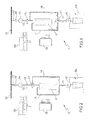
- A non-limiting embodiment of the present invention will be described by way of example with reference to the accompanying drawings, in which:
-
Figure 1 shows a view in perspective, with semitransparent parts and parts removed for clarity, of the top portion of a home refrigerator in accordance with the teachings of the present invention; -
Figure 2 shows schematically the cooled-drink dispenser integrated in theFigure 1 refrigerator; -
Figures 3 and 4 show two temperature charts illustrating operation of the cooled-drink dispenser integrated in theFigure 1 refrigerator; -
Figure 5 shows schematically a first variation of theFigure 1 cooled-drink dispenser; -
Figure 6 shows schematically a second variation of theFigure 1 cooled-drink dispenser. - With reference to
Figure 1 , number 1 indicates as a whole a household appliance for the controlled supplying of cooled water or other beverage. - More specifically, in the example shown household appliance 1 is a home refrigerator 1 incorporating a cooled-
drink dispenser 2 for controlled supply of cooled drinkable water or other beverage at a given temperature above 0°C and preferably, though not necessarily, ranging between +5°C and +20°C. - With reference to
figure 1 , in the example shown, refrigerator 1 comprises a rigid, self-supporting, substantially parallelepiped-shaped casing 3 having two superimposed refrigerated inner compartments 4 and 5, each of which is lined with thermally insulating material and communicates with the outside through a respective access opening formed in the vertical front wall of casing 3. - Refrigerator 1 also comprises two
doors 6 and 7 hinged, one over the other, to the vertical front wall of casing 3 to rotate, about a preferably, though not necessarily, common vertical axis, to and from a closed position, in which each rests against the vertical front wall of casing 3 to close the access opening to, and hermetically seal from the outside, a respective refrigerated compartment 4, 5. - With reference to
Figure 1 , refrigerator 1 also comprises a heat-pump cooling circuit 8 (shown partly inFigure 1 ) which transfers heat from one fluid to another by exploiting the changes in state of an intermediate gas refrigerant subjected to a closed thermodynamic cycle, and which is designed to bring each refrigerated compartment 4, 5 to, and keep it at, a respective predetermined reference temperature normally lower than the outside temperature. - The reference temperature is user-selectable within a predetermined temperature range.
- More specifically, in the example shown, heat-
pump cooling circuit 8 is designed to keep refrigerated compartment 4 (i.e. the top compartment of the refrigerator) at a reference temperature ranging between +1°C and +10°C and preferably, though not necessarily, between +2°C and +8°C, so refrigerated compartment 4 is suitable for preserving non-freezable perishable foodstuffs; and to keep refrigerated compartment 5 (i.e. the bottom compartment of the refrigerator) at a lower reference temperature than refrigerated compartment 4 (i.e. below 0°C) and preferably, though not necessary, ranging between -2°C and -20°C, so refrigerated compartment 5 is suitable for freezing perishable foodstuffs and/or producing ice. - In other words, top refrigerated compartment 4 constitutes the "fresh-food compartment", and bottom refrigerated compartment 5 the "frozen-food compartment" of refrigerator 1.
- Casing 3,
doors 6 and 7, and heat-pump cooling circuit 8 are commonly known parts in the industry and therefore not described in detail. - In the example shown, cooled-
drink dispenser 2 is integrated in thetop door 6 of refrigerator 1, but may obviously be located on the vertical front wall of casing 3, besidetop door 6 or bottom door 7 of refrigerator 1. - With reference to
Figures 1 and2 , cooled-drink dispenser 2 comprises atank 9 for temporarily storing drinkable water or any other beverage to be dispensed; and adraw valve 10, which is housed in adrink dispensing recess 6a formed in the outer surface oftop door 6, is connected totank 9 by a connectingpipe 11, and is designed to only permit controlled outflow of water or other beverage fromtank 9 to recess 6a whenrecess 6a is engaged by a glass or other container to receive the water. - More specifically,
tank 9 is housed inside refrigerated compartment 4, i.e. the fresh-food compartment 4, of refrigerator 1, next to the fan that circulates the cold air in fresh-food compartment 4 through the evaporator of heat-pump cooling circuit 8, so that the cold air also flows over the outer surfaces oftank 9 to cool and keep the water or other beverage intank 9 at the reference temperature of fresh-food compartment 4. - Obviously, in a different embodiment,
tank 9 may be housed inside an auxiliary compartment formed inside casing 3 ordoor 6, nearrecess 6a, and said auxiliary compartment may be cooled either by heat-pump cooling circuit 8, or by an independent cooling system such as a Peltier-effect cooling system. - With reference to
Figure 2 , cooled-drink dispenser 2 also comprises a second connectingpipe 12 permanently connectingtank 9 to a genericexternal source 13 of drinkable water or other beverage preferably, though not necessarily, at ambient temperature, so thattank 9 is always completely filled with drinkable water or other beverage; anelectric supply pump 14, along connectingpipe 12, for feeding drinkable water or other beverage, on command, along connectingpipe 12 at a given flow rate; atemperature detecting device 15 for determining the instantaneous temperature of the drinkable water or other beverage flowing along connectingpipe 12; and preferably, though not necessarily, an on-offvalve 16 for isolating connectingpipe 12, on command, fromsource 13 to cut off flow of the drinkable water or other beverage. - More specifically, in the example shown, on-off
valve 16 andtemperature detecting device 15 are located upstream and downstream frompump 14, respectively; andsource 13 is defined by the drinkable water circuit of the building in which refrigerator 1 is located. - Obviously,
source 13 may also consist of a common pressurized container storing a given quantity of drinkable water or other beverage. - With reference to
Figure 2 , along connectingpipe 12, downstream fromtemperature detecting device 15 and upstream fromtank 9, cooled-drink dispenser 2 also comprises an electrically operatedhydraulic distributor 17 designed, on command, to channel a given part of the drinkable water or other beverage flowing along connectingpipe 12, to an auxiliary connectingpipe 18 which bypassestank 9 and terminates directly inside connectingpipe 11, so as to divert at least part of the ambient-temperature water or other beverage fromsource 13 directly to drawvalve 10. - More specifically, in the example shown, the end of auxiliary connecting
pipe 18 is branch connected to connectingpipe 11, andhydraulic distributor 17 consists of a three-way electrovalve 17 having the inlet connected to connectingpipe 12, and the two outlets connected respectively to tank 9 and auxiliary connectingpipe 18, so that all the drinkable water or other beverage flowing along connectingpipe 12 can be channeled, on command, to tank 9 or auxiliary connectingpipe 18. - With reference to
figure 2 , cooled-drink dispenser 2 also comprises an electroniccentral control unit 19, which controlshydraulic distributor 17 on the basis of signals fromtemperature detecting device 15, and the selected temperature of the drinkable water or other beverage to be supplied by cooled-drink dispenser 2; and auser control panel 20, by which to communicate tocentral control unit 19 the selected temperature T0 of the drinkable water or other beverage to be supplied by cooled-drink dispenser 2. - In particular, detecting
device 15 measures the instantaneous current temperature T1 of the incoming drinkable water or other beverage fromsource 13; andcontrol unit 19 calculates the estimated current temperature T2 of the drinkable water or other beverage intank 9 on the basis of a tank cooling system mathematical model, which is specific for each model of refrigerator 1, and which describes the temperature T2 pattern of the drinkable water or other beverage intank 9 as a function of the time lapsed since draw-off of the last drink, and as a function of the temperature and amount of ambient-temperature drinkable water or other beverage fed intotank 9 fromsource 13 when drawing off the last drink, taking into account the real cooling capacity of the environment surrounding tank 9 (i.e. the tank cooling system formed, in the example shown, by fresh-food compartment 4 and heat-pump cooling circuit 8). - More specifically, in the examples shown,
control unit 19 calculates the estimated current temperature T2 of the drinkable water or other beverage intank 9 on the basis of a given number of experimentally-obtained work curves stored incontrol unit 19, and which describe the patterns of temperature T2 as a function of the time lapsed since draw-off of the last drink (Figure 4 ); and the patterns of temperature T2 as a function of the temperature T1 and of the amount Mx of cold water or other beverage last drawn off from tank 9 (Figure 3 ). - The cold water or other beverage drawn from
tank 9, in fact, is systematically replaced (either instantaneously or belatedly) by an equal amount of ambient-temperature water or other beverage fromsource 13. Ambient-temperature water or other beverage which has the temperature T1. - In fact, with reference to
Figure 3 , assuming that, immediately before the supply of the drink, the water or other beverage stored intank 9 is at a given minimum temperature depending on the environment surrounding tank 9 (i.e. the temperature of fresh-food compartment 4), the temperature T2 of the water or other beverage stored intank 9, after dispensing the drink, rises to a value T2' which depends on the amount Mx of ambient-temperature water or other beverage fromsource 13 that enters intank 9 to replace the cold water or other beverage drawn off fromtank 9, and on the actual temperature T1 of the ambient-temperature water or other beverage arriving fromsource 13. - Having a sufficient number of experimentally-obtained curves of the temperature T2' pattern as a function of the amount Mx of cold water or other beverage drawn off from
tank 9, each for a specific value of the temperature T1 of the water or other beverage arriving from source 13 (two temperature T2' patterns are shown inFigure 3 , one for temperature T1 equal to 14°C and the other for temperature T1 equal to 22°C),control unit 19 can calculate, immediately after having dispensed a drink, the estimated current temperature T2' of the drinkable water or other beverage intank 9 on the basis of the amount Mx of cold water or other beverage drawn off fromtank 9, and of the actual temperature T1 of the water or other beverage entering intank 9 fromsource 13. - Whereas, with reference to
Figure 4 , the time which cold water or other beverage stored intank 9 takes to return to the given minimum temperature of the environment surrounding tank 9 (i.e. the temperature of fresh-food compartment 4), depends on the cooling capacity of the environment surrounding tank 9 (i.e. the tank cooling system formed, in the example shown, by fresh-food compartment 4 and heat-pump cooling circuit 8), and it is a function of the temperature T2' of the drinkable water or other beverage stored intank 9 immediately after having dispensed last drink, and of the time lapsed since the supply of the last drink. - Having a sufficient number of experimentally-obtained curves of the temperature T2 time pattern, each for a specific temperature T2' starting value (two temperature T2 time patterns are shown in
Figure 4 , one for a temperature T2' starting value of 15°C and the other for a temperature T2' starting value of 20°C),control unit 19 can calculate the estimated current temperature T2 of the drinkable water or other beverage intank 9 when a new drink is requested, on the basis of lapsed time since draw-off of the last drink. - In addition to the above, after extrapolating the estimated current temperature T2 of the drinkable water or other beverage in
tank 9, electroniccentral control unit 19, implementing the calculating method referred below, is able to determine the amount M1 of drinkable water or other beverage at temperature T1 fromsource 13, and the amount M2 of cold water or other beverage at temperature T2 fromtank 9, to be mixed to obtain the drinkable water or other beverage at the user-selected temperature T0 fromdraw valve 10; and then to drivehydraulic distributor 17 to selectively split betweentank 9 and auxiliary connectingpipe 18 the drinkable water or other beverage flowing along connectingpipe 12, so as to channel to drawvalve 10 the calculated amount M1 of drinkable water or other beverage at temperature T1, and the calculated amount M2 of drinkable water or other beverage at estimated temperature T2. - More specifically, given the flow rate of the ambient-temperature water or other beverage fed along connecting
pipe 12 byelectric supply pump 14, electroniccentral control unit 19 drives, or rather quickly switches, three-way electrovalve 17 so that the drinkable water or other beverage flowing along connectingpipe 12 is selectively channeled to tank 9 or directly to drawvalve 10 according to the calculated amounts M1 and M2. In fact, the flow rate of the water or other beverage along connectingpipe 12 being known and constant, the amount M2 of drinkable water or other beverage channeled totank 9 is a direct function of the time interval in whichhydraulic distributor 17 connectspipe 12 totank 9; and the amount M1 of drinkable water or other beverage channeled directly to drawvalve 10 is a direct function of the time interval in whichhydraulic distributor 17 connectspipe 12 toauxiliary connecting pipe 18. - Operation of household appliance 1 as a whole, i.e. home refrigerator 1, is clearly inferable from the above description, with no further explanation required, whereas operation of cooled-
drink dispenser 2 will now be described, assuming the user has already communicated to controlunit 19, viacontrol panel 20, the selected temperature T0 of the drinkable water or other beverage to be supplied immediately by cooled-drink dispenser 2. - On receiving the selected temperature T0 of the drinkable water or other beverage to be dispensed, electronic
central control unit 19 determines the current temperature T1 of the drinkable water or other beverage fromsource 13 viatemperature detecting device 15, and calculates, using the tank cooling system mathematical model, the estimated current temperature T2 of the drinkable water or other beverage intank 9 on the basis of the time lapsed since draw-off of last drink by cooled-drink dispenser 2; of the temperature T1 of the drinkable water or other beverage fromsource 13 at the time of last drink draw-off; and of the amount Mx of cold water or other beverage drawn fromtank 9 during draw-off of the last drink by cooled-drink dispenser 2. - After calculating the estimated temperature T2 of the drinkable water or other beverage currently stored in
tank 9, electroniccentral control unit 19 determines the amounts M1 and M2 of drinkable water or other beverage to be channeled to drawvalve 10, on the basis of the following two-equation system: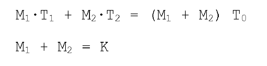
where K is a predetermined constant value preferably, though not necessarily, equal to 100 milliliters; T0 is the selected temperature of the drinkable water or other beverage to be supplied by cooled-drink dispenser 2; T1 is the current temperature of the drinkable water or other beverage fromsource 13; and T2 is the estimated current temperature of the cooled drinkable water or other beverage stored intank 9. - Finally, on the basis of the calculated amounts M1 and M2 of drinkable water or other beverage to be channeled to, and mixed in, draw
valve 10, and the flow rate of the ambient-temperature water or other beverage flowing along connectingpipe 12, electroniccentral control unit 19 activatessupply pump 14 and regulates the switching time of three-way electrovalve 17 so that the calculated amounts M1 and M2 of drinkable water or other beverage are channeled to auxiliary connectingpipe 18 andtank 9 respectively. - In other words, since auxiliary connecting
pipe 18 is connected directly to drawvalve 10, and the ambient-temperature water or other beverage channeled intotank 9 byhydraulic distributor 17 feeds out oftank 9 an equal amount of cold water or other beverage via connectingpipe 11, electroniccentral control unit 19 regulates the switching time of three-way electrovalve 17 to channel the calculated amounts M1 and M2 of drinkable water or other beverage to drawvalve 10, and so supply the user with cooled water or other beverage at user-selected temperature T0. - The advantages of cooled-
drink dispenser 2 are obvious: it provides for supplying drinks at different user-selected temperatures in a low-cost manner, and with no need for auxiliary heating devices. - Clearly, changes may be made to household appliance 1 as described herein without, however, departing from the scope of the present invention.
- For example, with reference to
Figure 5 , electrically operatedhydraulic distributor 17 may be located along connectingpipe 11, upstream fromdraw valve 10. - In which case, one of the two outlets of
hydraulic distributor 17 is connected to connectingpipe 11; the other outlet ofhydraulic distributor 17 is connected to the bottom end of auxiliary connectingpipe 18; and the inlet ofhydraulic distributor 17 is connected to drawvalve 10. Lastly the top end of auxiliary connectingpipe 18 is branch connected to connectingpipe 12. - In a further non shown embodiment,
electric supply pump 14 may be replaced by a flow rate detecting device for measuring the current flow rate of drinkable water or other beverage along connectingpipe 12, and by an electrovalve for controlling outflow of ambient-temperature drinkable water or other beverage along connectingpipe 12. Obviously, the electrovalve is controlled by electroniccentral control unit 19, and selectively opened for drink supply by cooled-drink dispenser 2; whereas three-way electrovalve 17 is driven on the basis of signals from the flow rate detecting device. - With reference to
Figure 6 , in a much more sophisticated embodiment,electric supply pump 14 is removed from cooled-drink dispenser 2, and the two ends of auxiliary connectingpipe 18 are branch connected respectively to connectingpipe 11, and to connectingpipe 12. - In which case, electrically operated
hydraulic distributor 17 comprises two independent electro-valves 17' and 17" located one along connectingpipe 12, downstream from the connection between connectingpipe 12 and auxiliary connectingpipe 18 and upstream fromtank 9, and the other along auxiliary connectingpipe 18, for separately and independently controlling the flow of ambient-temperature drinkable water or other beverage fromsource 13 totank 9, and fromsource 13 to auxiliary connectingpipe 18. - Both electro-
valves 17' and 17" are controlled by electroniccentral control unit 19 independently one form the other, and cooled-drink dispenser 2 also comprises two flowrate detecting devices 21 which are located along connectingpipe 12 and, respectively, auxiliary connectingpipe 18, downstream from corresponding electro-valves 17' and 17", for measuring the current flow rate of the drinkable water or other beverage flowing towardstank 9 and along connectingpipe 18. - Obviously,
central control unit 19 drives both electro-valve 17' and 17" on the basis of the signals from the two flowrate detecting devices 21, and from thetemperature detecting device 15 which is still located along connectingpipe 12, preferably, though not necessarily, upstream from the connection between connectingpipe 12 andauxiliary connecting pipe 18. - In combination with all the embodiments referred above, household appliance 1 may also consist of a stand-alone beverage dispenser, a food and/or beverage vending machine or any other kind of beverage dispensing apparatus.
Claims (14)
- Household appliance (1) for the controlled supplying of cooled water or other beverage, and comprising:- a beverage container (9) to store a given amount of drinkable water or other beverage,- a beverage container cooling system (4, 8) for cooling the drinkable water or other beverage stored in the beverage container (9),- a first connecting pipe (12) connecting said beverage container (9) to a beverage source (13) supplying drinkable water or other beverage at a generic temperature, and- a user-controlled draw device (10) connected to said beverage container (9) to control outflow of the cooled drinkable water or other beverage;
said household appliance (1) being characterized by also comprising :- a temperature detecting device (15) for detecting the current temperature (T1) of the drinkable water or other beverage arriving from said beverage source (13),- electrically-operated mixing means (17, 18) for mixing, on command, a given amount of the drinkable water or other beverage arriving directly from said beverage source (13), and a given amount of the cold water or other beverage flowing out of the beverage container (9) to said user-controlled draw device (10), and- an electronic central control unit (19), which calculates the estimated current temperature (T2) of the cooled drinkable water or other beverage in the beverage container (9) on the basis of a given mathematical model describing the cooling capacity of the beverage container cooling system (4, 8); said central control unit (19) also calculating, according to a given algorithm, and on the basis of the selected temperature (T0) of the drinkable water or other beverage to be supplied by said household appliance (1), of the temperature (T1) of the drinkable water or other beverage arriving directly from the beverage source (13), and of the estimated current temperature (T2) of the cooled drinkable water or other beverage stored in the beverage container (9), a first amount (M1) of drinkable water or other beverage arriving directly from the beverage source (13), and a second amount (M2) of cold water or other beverage from the beverage container (9), to be mixed together to obtain drinkable water or other beverage at the specific user-selected temperature (T0) from the draw device (10), and driving said electrically-operated mixing means (17, 18) to supply said draw device (10) with said first amount (M1) of drinkable water or other beverage arriving directly from the beverage source (13), and said second amount (M2) of cold water or other beverage from the beverage container (9). - A household appliance as claimed in Claim 1,
characterized by also comprising a user control panel (20) by which to communicate to said central control unit (19) the selected temperature (T0) of the drinkable water or other beverage to be dispensed. - A household appliance as claimed in Claim 1 or 2,
characterized in that said electrically-operated mixing means (17, 18) are designed to channel, on command, directly to said draw device (10), at least part of the drinkable water or other beverage flowing along the first connecting pipe (12). - A household appliance as claimed in Claim 3,
characterized in that said electrically-operated mixing means (17, 18) comprise an electrically-operated hydraulic distributor (17) located along said first connecting pipe (12); and an auxiliary connecting pipe (18) connecting said electrically-operated hydraulic distributor (17) to said draw device (10) and bypassing the beverage container (9). - A household appliance as claimed in Claim 3,
characterized in that said electrically-operated mixing means (17, 18) comprise an electrically-operated hydraulic distributor (17) interposed between the beverage container (9) and the draw device (10); and an auxiliary connecting pipe (18) connecting said electrically-operated hydraulic distributor (17) to said first connecting pipe (12) and bypassing said beverage container (9). - A household appliance as claimed in Claim 4 or 5,
characterized in that said hydraulic distributor (17) is a three-way electrovalve (17). - A household appliance as claimed in any of the foregoing Claims, characterized in that said cooled-drink dispenser (2) comprises pumping means (14) for feeding the drinkable water or other beverage along said first connecting pipe (12) at a given flow rate; said central control unit (19) also driving said electrically-operated mixing means (17, 18) on the basis of said flow rate.
- A household appliance as claimed in any of Claims 1 to 6, characterized by also comprising means for measuring the flow rate of the drinkable water or other beverage along said first connecting pipe (12); and means for controlling outflow of the drinkable water or other beverage along said first connecting pipe (12); said means for controlling outflow of the drinkable water or other beverage along said first connecting pipe (12) being controlled by said central control unit (19).
- A household appliance as claimed in Claim 4,
characterized in that said hydraulic distributor (17) comprises two electrovalves (17', 17") located one along said auxiliary connecting pipe (18), and the other along said first connecting pipe (12), downstream from the connection between said first connecting pipe (12) and said auxiliary connecting pipe (18); said two electrovalves (17', 17") being able to separately and independently control the flow of drinkable water or other beverage from the beverage source (13) to the beverage container (9), and from the beverage source (13) to the auxiliary connecting pipe (18). - A household appliance as claimed in Claims 9,
characterized by also comprising means (21) for measuring the flow rate of the drinkable water or other beverage flowing into said beverage container (9), and along said auxiliary connecting pipe (18); said two electrovalves (17', 17") being controlled by said central control unit (19) on the basis of the signals from said means (21) for measuring the flow rate of the drinkable water or other beverage flowing into said beverage container (9) and along said auxiliary connecting pipe (18). - A household appliance as claimed in any of the foregoing Claims, characterized in that said household appliance is a refrigerator (1) and the beverage container (9) is housed inside a refrigerated compartment (4) of said refrigerator (1).
- A method of operating a household appliance (1) for the controlled supplying of cooled water or other beverage, and comprising:- a beverage container (9) to store a given amount of drinkable water or other beverage,- a beverage container cooling system (4, 8) for cooling the drinkable water or other beverage stored in the beverage container (9),- a first connecting pipe (12) connecting said beverage container (9) to an beverage source (13) supplying drinkable water or other beverage at a generic temperature, and- a user-controlled draw device (10) connected to said beverage container (9) to control outflow of the cooled drinkable water or other beverage into a glass or other generic receptacle;- a temperature detecting device (15) for determining the current temperature (T1) of the drinkable water or other beverage arriving from said beverage source (13), and- electrically-operated mixing means (17, 18) for mixing, on command, a given amount of the drinkable water or other beverage flowing directly arriving from said beverage source (13), and a given amount of the cold water or other beverage flowing out of the beverage container (9) to said user-controlled draw device (10);
said method being characterized by comprising the steps of:- measuring the temperature (T1) of the drinkable water or other beverage from said beverage source (13);- calculating an estimated current temperature (T2) of the cooled drinkable water or other beverage in the beverage container (9) on the basis of a given mathematical model describing the cooling capacity of the environment (4, 8) surrounding the beverage container (9);- calculating, according to a given algorithm, and on the basis of the current temperature (T1) of the drinkable water or other beverage from the beverage source (13), and of the estimated current temperature (T2) of the cooled drinkable water or other beverage in the beverage container (9), a first amount (M1) of ambient-temperature drinkable water or other beverage from the beverage source (13), and a second amount (M2) of cold water or other beverage from the beverage container (9), to be mixed together to obtain drinkable water or other beverage at a specific user-selected temperature (T0) from the draw device (10); and- driving said electrically-operated mixing means (17, 18) to supply said draw device (10) with said first amount (M1) of drinkable water or other beverage from the beverage source (13), and said second amount (M2) of cold water or other beverage from the beverage container (9). - A method as claimed in Claim 12, characterized in that said first amount (M1) of drinkable water or other beverage from the beverage source (13), and said second amount (M2) of cold water or other beverage from the beverage container (9), are determined on the basis of the following two-equation system:
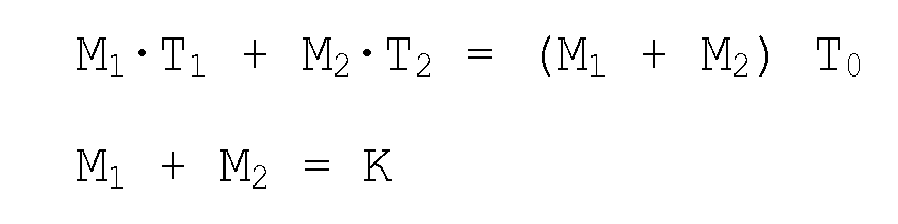
where K is a predetermined constant value, T0 is the selected temperature of the drinkable water or other beverage to be supplied by the household appliance (1), T1 is the current temperature of the drinkable water or other beverage from the beverage source (13), and T2 is the estimated current temperature of the cooled drinkable water or other beverage stored in the beverage container (9). - A method as claimed in Claim 12 or 13,
characterized in that said household appliance (1) is a refrigerator.
Priority Applications (1)
| Application Number | Priority Date | Filing Date | Title |
|---|---|---|---|
| EP08151713A EP2093529A1 (en) | 2008-02-20 | 2008-02-20 | Household appliance for the controlled supplying of cooled water or other beverage, and relative operating method |
Applications Claiming Priority (1)
| Application Number | Priority Date | Filing Date | Title |
|---|---|---|---|
| EP08151713A EP2093529A1 (en) | 2008-02-20 | 2008-02-20 | Household appliance for the controlled supplying of cooled water or other beverage, and relative operating method |
Publications (1)
| Publication Number | Publication Date |
|---|---|
| EP2093529A1 true EP2093529A1 (en) | 2009-08-26 |
Family
ID=39427496
Family Applications (1)
| Application Number | Title | Priority Date | Filing Date |
|---|---|---|---|
| EP08151713A Withdrawn EP2093529A1 (en) | 2008-02-20 | 2008-02-20 | Household appliance for the controlled supplying of cooled water or other beverage, and relative operating method |
Country Status (1)
| Country | Link |
|---|---|
| EP (1) | EP2093529A1 (en) |
Cited By (2)
| Publication number | Priority date | Publication date | Assignee | Title |
|---|---|---|---|---|
| WO2012175118A1 (en) * | 2011-06-21 | 2012-12-27 | Electrolux Home Products Corporation N.V. | Household appliance with beverage dispensing system, method and filter cartridge |
| CN115919149A (en) * | 2022-12-04 | 2023-04-07 | 江苏星星冷链科技有限公司 | A multi-functional freezer low-temperature drinking water automatic system device |
Citations (2)
| Publication number | Priority date | Publication date | Assignee | Title |
|---|---|---|---|---|
| GB2329460A (en) * | 1997-09-23 | 1999-03-24 | Lg Electronics Inc | Refrigerator dispenser assembly |
| EP1614986A2 (en) * | 2004-06-28 | 2006-01-11 | Daewoo Electronics Corporation | Refrigerator door with a carbonator installed therein |
-
2008
- 2008-02-20 EP EP08151713A patent/EP2093529A1/en not_active Withdrawn
Patent Citations (2)
| Publication number | Priority date | Publication date | Assignee | Title |
|---|---|---|---|---|
| GB2329460A (en) * | 1997-09-23 | 1999-03-24 | Lg Electronics Inc | Refrigerator dispenser assembly |
| EP1614986A2 (en) * | 2004-06-28 | 2006-01-11 | Daewoo Electronics Corporation | Refrigerator door with a carbonator installed therein |
Cited By (4)
| Publication number | Priority date | Publication date | Assignee | Title |
|---|---|---|---|---|
| WO2012175118A1 (en) * | 2011-06-21 | 2012-12-27 | Electrolux Home Products Corporation N.V. | Household appliance with beverage dispensing system, method and filter cartridge |
| US9199835B2 (en) | 2011-06-21 | 2015-12-01 | Electrolux Home Products Corporation | Household appliance with beverage dispensing system, method and filter cartridge |
| AU2011371325B2 (en) * | 2011-06-21 | 2016-12-01 | Electrolux Home Products Corporation N.V. | Household appliance with beverage dispensing system, method and filter cartridge |
| CN115919149A (en) * | 2022-12-04 | 2023-04-07 | 江苏星星冷链科技有限公司 | A multi-functional freezer low-temperature drinking water automatic system device |
Similar Documents
| Publication | Publication Date | Title |
|---|---|---|
| CA2639249C (en) | Variable temperature dispenser system and method | |
| US6761036B2 (en) | Beverage dispenser with integral ice maker | |
| JP6190899B2 (en) | Hot and cold beverage dispensers | |
| US12031767B2 (en) | Free-standing ice or beverage dispensing appliance | |
| US9568240B2 (en) | Refrigerator appliance with hot water dispenser | |
| EP2682691B1 (en) | Refrigerator | |
| US9297574B2 (en) | Refrigerator and method for controlling the same | |
| CA2674507C (en) | Ice making and water delivery apparatus | |
| US20100287971A1 (en) | Refrigerator and control method thereof | |
| EP3182044B1 (en) | Refrigerating device for preparing frozen drink | |
| EP1162168B1 (en) | A multi-tank beverage dispenser with individual cooling means for each tank and method of controlling | |
| CA2830781A1 (en) | Hot/cold beverage dispenser and method | |
| US11326825B2 (en) | Stand-alone ice and beverage appliance | |
| KR20160005340A (en) | Refrigerator appliance with hot water dispenser | |
| US7814763B2 (en) | Refrigeration appliance with a water dispenser | |
| KR101512123B1 (en) | Refrigerator | |
| US20080179346A1 (en) | Method and assembly for dispensing semi-frozen beverages | |
| JP3732997B2 (en) | Beverage supply equipment | |
| JPH08156997A (en) | Drink dispenser | |
| AU2011371325B2 (en) | Household appliance with beverage dispensing system, method and filter cartridge | |
| WO2008037383A1 (en) | Household appliance for the supplying of cooled water or other beverage and relative operation method | |
| KR20090119480A (en) | Refrigerator | |
| EP2042823A1 (en) | Home refrigerator with a cooled-drink dispenser | |
| HK1261274A1 (en) | Refrigerated post-mix dispenser | |
| JPH1118683A (en) | Apparatus for pouring frozen dessert |
Legal Events
| Date | Code | Title | Description |
|---|---|---|---|
| PUAI | Public reference made under article 153(3) epc to a published international application that has entered the european phase |
Free format text: ORIGINAL CODE: 0009012 |
|
| AK | Designated contracting states |
Kind code of ref document: A1 Designated state(s): AT BE BG CH CY CZ DE DK EE ES FI FR GB GR HR HU IE IS IT LI LT LU LV MC MT NL NO PL PT RO SE SI SK TR |
|
| AX | Request for extension of the european patent |
Extension state: AL BA MK RS |
|
| AKX | Designation fees paid | ||
| REG | Reference to a national code |
Ref country code: DE Ref legal event code: 8566 |
|
| STAA | Information on the status of an ep patent application or granted ep patent |
Free format text: STATUS: THE APPLICATION IS DEEMED TO BE WITHDRAWN |
|
| 18D | Application deemed to be withdrawn |
Effective date: 20100227 |