EP2093512A1 - Indoor unit for air conditioner - Google Patents
Indoor unit for air conditioner Download PDFInfo
- Publication number
- EP2093512A1 EP2093512A1 EP06833962A EP06833962A EP2093512A1 EP 2093512 A1 EP2093512 A1 EP 2093512A1 EP 06833962 A EP06833962 A EP 06833962A EP 06833962 A EP06833962 A EP 06833962A EP 2093512 A1 EP2093512 A1 EP 2093512A1
- Authority
- EP
- European Patent Office
- Prior art keywords
- airflow path
- case
- indoor unit
- motor
- output shaft
- Prior art date
- Legal status (The legal status is an assumption and is not a legal conclusion. Google has not performed a legal analysis and makes no representation as to the accuracy of the status listed.)
- Withdrawn
Links
Images



Classifications
-
- F—MECHANICAL ENGINEERING; LIGHTING; HEATING; WEAPONS; BLASTING
- F24—HEATING; RANGES; VENTILATING
- F24F—AIR-CONDITIONING; AIR-HUMIDIFICATION; VENTILATION; USE OF AIR CURRENTS FOR SCREENING
- F24F1/00—Room units for air-conditioning, e.g. separate or self-contained units or units receiving primary air from a central station
- F24F1/0007—Indoor units, e.g. fan coil units
- F24F1/0011—Indoor units, e.g. fan coil units characterised by air outlets
-
- F—MECHANICAL ENGINEERING; LIGHTING; HEATING; WEAPONS; BLASTING
- F24—HEATING; RANGES; VENTILATING
- F24F—AIR-CONDITIONING; AIR-HUMIDIFICATION; VENTILATION; USE OF AIR CURRENTS FOR SCREENING
- F24F1/00—Room units for air-conditioning, e.g. separate or self-contained units or units receiving primary air from a central station
- F24F1/0007—Indoor units, e.g. fan coil units
- F24F1/0043—Indoor units, e.g. fan coil units characterised by mounting arrangements
- F24F1/0057—Indoor units, e.g. fan coil units characterised by mounting arrangements mounted in or on a wall
-
- F—MECHANICAL ENGINEERING; LIGHTING; HEATING; WEAPONS; BLASTING
- F24—HEATING; RANGES; VENTILATING
- F24F—AIR-CONDITIONING; AIR-HUMIDIFICATION; VENTILATION; USE OF AIR CURRENTS FOR SCREENING
- F24F13/00—Details common to, or for air-conditioning, air-humidification, ventilation or use of air currents for screening
- F24F13/08—Air-flow control members, e.g. louvres, grilles, flaps or guide plates
- F24F13/10—Air-flow control members, e.g. louvres, grilles, flaps or guide plates movable, e.g. dampers
- F24F13/14—Air-flow control members, e.g. louvres, grilles, flaps or guide plates movable, e.g. dampers built up of tilting members, e.g. louvre
- F24F13/1426—Air-flow control members, e.g. louvres, grilles, flaps or guide plates movable, e.g. dampers built up of tilting members, e.g. louvre characterised by actuating means
- F24F2013/1433—Air-flow control members, e.g. louvres, grilles, flaps or guide plates movable, e.g. dampers built up of tilting members, e.g. louvre characterised by actuating means with electric motors
-
- F—MECHANICAL ENGINEERING; LIGHTING; HEATING; WEAPONS; BLASTING
- F24—HEATING; RANGES; VENTILATING
- F24F—AIR-CONDITIONING; AIR-HUMIDIFICATION; VENTILATION; USE OF AIR CURRENTS FOR SCREENING
- F24F13/00—Details common to, or for air-conditioning, air-humidification, ventilation or use of air currents for screening
- F24F13/22—Means for preventing condensation or evacuating condensate
- F24F2013/221—Means for preventing condensation or evacuating condensate to avoid the formation of condensate, e.g. dew
Definitions
- the present invention relates to an indoor unit for an air conditioner, provided with a motor for driving horizontal airflow direction louvers.
- an indoor unit for an air conditioner provided with a motor for driving horizontal airflow direction louvers, has been conventionally produced.
- a through hole is formed in a sidewall forming an airflow path.
- a coupling rod of horizontal airflow direction louvers is coupled to a motor and mechanical components (e.g., a link), disposed outside the airflow path in the interior of a main body of the indoor unit, via the through hole.
- conditioned air produced as a result of cooling of air by an indoor heat exchanger, may leak out of the airflow path via the through hole, and thereby condensation may occur in the motor and the mechanical components.
- the indoor unit described in Patent Document 1 is provided with a cover for blocking the motor and the mechanical components from external air.
- it is difficult to completely block heat transfer between the inside and the outside of the main body of the indoor unit. Therefore, it is difficult to inhibit occurrence of condensation in the motor and the mechanical components.
- An object of the present invention is to provide an indoor unit for an air conditioner for preventing occurrence of condensation in a motor and mechanical components due to leakage of conditioned air from an airflow path to a driving unit of airflow direction change means.
- An indoor unit for an air conditioner includes an airflow path formation member, airflow direction change means and a driving unit.
- the airflow path formation member is a member for forming an airflow path.
- the airflow direction change means is disposed in the interior of the airflow path.
- the airflow direction change means is configured to change an airflow direction of a conditioned air to be blown out to an indoor space.
- the driving unit is disposed outside the airflow path.
- the driving unit is configured to drive the airflow direction change means.
- the driving unit includes a motor, a mechanical component, a case and a rotation output shaft.
- the mechanical component is configured to transmit power of the motor.
- the case covers the motor and the mechanical component.
- the rotation output shaft is configured to output power of the motor to the outside of the case after receiving transmission of power of the motor through the mechanical component.
- the airflow path formation member includes a first through hole.
- the first through hole is formed for allowing the rotation output shaft to reach the inside of the airflow path therethrough.
- a periphery of the first through hole includes a blocking structure.
- the blocking structure is configured to block communication between the airflow path and the interior of the driving unit.
- the blocking structure is formed for blocking communication between the airflow path and the interior of the driving unit.
- An indoor unit for an air conditioner according to a second aspect of the present invention is the indoor unit according to the first aspect of the present invention.
- the blocking structure includes a first engagement part.
- the first engagement part is formed by engagement of the rotation output shaft and the first through hole formed in the airflow path formation member.
- the blocking structure includes the first engagement part formed by the engagement between the rotation output shaft and the first through hole formed in the airflow path formation member. Accordingly, it is possible to prevent leakage of conditioned air with the engagement between the rotation output shaft and the first through hole formed in the airflow path formation member.
- An indoor unit for an air conditioner according to a third aspect of the present invention is the indoor unit according to the second aspect of the present invention.
- the first engagement part further includes sealing material. The sealing material is applied between the rotation output shaft and the inner peripheral surface of the first through hole.
- the first engagement part further includes the sealing material applied between the rotation output shaft and the inner peripheral surface of the first through hole.
- An indoor unit for an air conditioner according to a fourth aspect of the present invention is the indoor unit according to the third aspect of the present invention.
- the sealing material is grease.
- the sealing material is grease. Therefore, it is possible to enhance a leakage prevention effect for conditioned air. Furthermore, it is possible to enhance lubrication of the rotation output shaft.
- An indoor unit for an air conditioner according to a fifth aspect of the present invention is the indoor unit according to one of the first to fourth aspects of the present invention.
- the blocking structure includes a second engagement part.
- the second engagement part is formed by engagement between the rotation output shaft and the second through hole formed in the case.
- the blocking structure includes the second engagement part formed by the engagement between the rotation output shaft and the second through hole formed in the case. Accordingly, it is possible to block leakage of conditioned air with the engagement between the rotation output shaft and the second through hole formed in the case.
- An indoor unit for an air conditioner according to a sixth aspect of the present invention is the indoor unit according to the second aspect of the present invention.
- the blocking structure includes a third engagement part.
- the third engagement part is formed by engagement between a convex part and a concave part.
- the convex part is formed in a periphery of the first through hole formed in the airflow path formation member.
- the concave part is formed in the case.
- the blocking structure includes the third engagement part formed by the engagement between the convex part formed in the periphery of the first through hole formed in the airflow path formation member and the concave part formed in the case. Accordingly, the engagement between the convex part of the airflow path formation member and the concave part of the case enhances adhesiveness between the rotation output shaft and the inner peripheral surface of the first through hole. Consequently, it is possible to further enhance a leakage prevention effect for conditioned air.
- An indoor unit for an air conditioner according to a seventh aspect of the present invention is the indoor unit according to one of the first to sixth aspects of the present invention.
- the indoor unit further includes an air layer formation part for forming an air layer on a surface of the case opposing to the airflow path formation member.
- the indoor unit further includes the air layer formation part for forming the air layer on the surface of the case opposing to the airflow path formation member. Accordingly, the air layer prevents heat transfer between the airflow path and the interior of the case. Consequently, it is possible to prevent occurrence of condensation due to temperature reduction of air in the interior of the case.
- An indoor unit for an air conditioner according to an eighth aspect of the present invention is the indoor unit according to the seventh aspect of the present invention.
- the air layer formation part includes a plurality of ribs. Additionally, the air layer is formed between adjacent two ribs.
- the air layer formed between adjacent two ribs, blocks heat transfer between the airflow path and the interior of the case. Accordingly, it is possible to prevent occurrence of condensation due to temperature reduction of air in the interior of the case.
- An indoor unit for an air conditioner according to a ninth aspect of the present invention is the indoor unit according to one of the first to eighth aspects of the present invention.
- the indoor unit further includes a heat insulator.
- the heat insulator ism disposed between the airflow path formation member and the case.
- the heat insulator disposed between the airflow path formation member and the case, blocks heat transfer between the airflow path and the interior of the case. Accordingly, it is possible to prevent occurrence of condensation due to temperature reduction of air in the interior of the case.
- the first aspect of the present invention it is possible to prevent occurrence of condensation in the motor and the mechanical components due to leakage of conditioned air from the airflow path to the driving unit for the airflow direction change means.
- air tightness in the first engagement part is enhanced, and it is thereby possible to enhance a leakage prevention effect for conditioned air.
- the fourth aspect of the present invention it is possible to enhance a leakage prevention effect for conditioned air, and is also possible to enhance lubrication of the rotation output shaft.
- the engagement between the convex part of the airflow path formation member and the concave part of the case enhances adhesiveness between the rotation output shaft and the inner peripheral surface of the first through hole. Accordingly, it is possible to enhance a leakage prevention effect for conditioned air.
- the air layer prevents heat transfer between the airflow path and the interior of the case. Accordingly, it is possible to prevent occurrence of condensation due to temperature reduction of air in the interior of the case.
- the air layer formed between adjacent two ribs, blocks heat transfer between the airflow path and the interior of the case. Accordingly, it is possible to prevent occurrence of condensation due to temperature reduction of air in the interior of the case.
- the heat insulator disposed between the airflow path formation member and the case, blocks heat transfer between the airflow path and the interior of the case. Accordingly, it is possible to prevent occurrence of condensation due to temperature reduction of air in the interior of the case.
- Fig. 1 is a vertical cross-sectional view for illustrating an interior structure of an indoor unit for an air conditioner according to an embodiment of the present invention.
- An indoor unit 1 is attached to a wall of an indoor space and the like.
- the indoor unit 1 is mainly composed of a bottom case 2, a top case 3, a main body section, horizontal airflow path direction louvers 5 and a driving unit 6.
- the bottom base 2 includes an airflow formation part 2a.
- the main body section includes an indoor heat exchanger 4 and a cross-flow fan 8.
- the horizontal airflow direction louvers 5 function as airflow direction change means.
- the bottom case 2 covers the bottom side and the back side of the main body section including the indoor heat exchanger 4, the cross-flow fan 8 and the like.
- the top case 3 is engaged with the bottom case 2 for covering the front side of the main body section.
- the airflow path formation part 2a forming a flow path 7, is formed above the upper surface of the bottom case 2.
- the airflow path formation part 2a includes a first through hole 15 formed for allowing a rotation output shaft 14 to reach the inside of the airflow path 7 therethrough.
- the top case 3 forms a front part of the indoor unit 1.
- the top case 3 is provided with suction ports 3a and 3b.
- the indoor heat exchanger 4 is opposed to the circumferential surface of the cross-flow fan 8.
- the indoor heat exchanger 4 is attached to the indoor unit 1 so as to surround the cross-flow fan 8 from the above, front and behind thereof.
- the indoor heat exchanger 4 is configured to conduct heat exchange between refrigerant passing through the interior of the indoor heat exchanger 4 and air to be sucked into the cross-flow fan 8 through the suction ports 3a and 3b when the cross-flow fan 8 is rotated.
- the top case 3 is provided with a blow-out port 9.
- the blow-out port 9 is composed of an opening formed along an elongated direction (i.e., width direction) of the indoor unit 1. Airflow, generated by the cross-flow fan 8, is blown out of the blow-out port 9 to the indoor space.
- the airflow path 7 appropriately regulates airflow produced by the cross-flow fan 8, and guides it to the blow-out port 9.
- the airflow path 7 is formed by the combination of the bottom case 2 and the top case 3.
- a plurality of the horizontal airflow direction louvers 5 and a plurality of horizontal flaps 10 are provided in the airflow path 7.
- FIG. 2 upper portions of a plurality of the horizontal airflow direction louvers 5 are attached to an attachment plate 20.
- Each of the horizontal airflow direction louvers 5 is thereby allowed to swing from side to side.
- the attachment plate 20 is fixed to the bottom case 2.
- a plurality of the horizontal airflow direction louvers 5 are coupled to the rotation output shaft 14 through coupling pins 19, a coupling rod 17, a coupling pin 18 and an arm 16 for swinging from side to side by means of rotation drive force of the rotation output shaft 14 of the driving unit 6.
- a plurality of the horizontal airflow direction louvers 5 is coupled to the common coupling rod 17 through the coupling pin 19.
- Each of the horizontal airflow direction louvers 5 is coupled to the coupling rod 17 for rotating about the coupling pin 19.
- the coupling rod 17 is coupled to the arm 16 through the coupling pin 18 while the arm 16 is fixed to the rotation output shaft 14.
- the coupling rod 17 is coupled to the arm 16 for rotating around the coupling pin 18.
- the horizontal flaps 10 are configured to guide airflow to be blown out to the indoor space up and down.
- the horizontal flaps 10 are disposed in a vicinity of the blow-out port 9.
- the horizontal flaps 10 are rectangular-shaped plate members elongated in an elongated direction of the blow-out port 9. Each of the horizontal flaps 10 is allowed to rotate about an axis parallel to the elongated of the blow-out port 9.
- the horizontal flaps 10 are rotationally driven by a flap motor (not illustrated in the figure). Accordingly, the horizontal flaps 10 are capable of guiding airflow up and down, and are also capable of closing the blow-out port 9.
- the driving unit 6 includes a motor 11, a link mechanism 12, a case 13, and the rotation output shaft 14.
- the link mechanism 12 is a mechanical component for transmitting power of the motor 11.
- the case 13 covers the motor 11 and the link mechanism 12.
- the rotation output shaft 14 is configured to output power of the motor 11, which is transmitted through the link mechanism 12, to the outside the case 13.
- the motor 11 is composed of a stepping motor.
- the motor 11 is capable of selecting a direction of rotation (either a clockwise direction or a counter-clockwise direction) and an angle of rotation corresponding to an input signal, and is capable of transmitting rotation drive force to the link mechanism 12 based on the selected direction and angle of rotation.
- the link mechanism 12 is configured to transmit the rotation drive force of the motor 11 to the rotation output shaft 14.
- the link mechanism 12 is composed of a first arm 12a, a coupling rod 12b, a coupling pin 12c, a second arm 12d and a coupling pin 12e.
- the first arm 12a is coupled to a driving shaft 11a of the motor 11.
- the coupling pin 12c couples the first arm 12a and the coupling rod 12b for allowing them to couple rotatably.
- the second arm 12d is coupled to the rotation output shaft 14.
- the coupling pin 12e couples the coupling rod 12b and the second arm 12d for allowing them to couple rotatably.
- the case 13 is composed of a case body 13a opened downward and a bottom cover 13b.
- a blocking structure is formed in a periphery of the first through hole 15 formed in the airflow path formation part 2a of the bottom case 2.
- the blocking structure is configured to block communication between the airflow path 7 and the interior of the driving unit 6.
- the blocking structure according to the present embodiment includes three engagement parts: a first engagement part 21; a second engagement part 23; and a third engagement part 27.
- the first engagement part 21 is formed by engagement between the rotation output shaft 14 and the first through hole 15 formed in the airflow path formation part 2a of the bottom case 2.
- the first engagement part 21 further includes grease 22 as sealing material applied between the rotation output shaft 14 and the inner peripheral surface of the first through hole 15. With the grease 22, it is possible to further effectively enhance an effect for preventing conditioned air from leaking from the first through hole 15. With the grease 22, and also, it is possible to enhance lubrication of the rotation output shaft 14.
- the second engagement part 23 is formed by engagement between the rotation output shaft 14 and a second through hole 24 formed in the case 13.
- the third engagement part 27 is formed by engagement between a convex part 28 and a concave part 29.
- the convex part 28 is formed in a periphery of the first through hole 15 formed in the airflow path formation part 2a of the bottom case 2.
- the concave part 29 is formed in the case 13.
- the indoor unit 1 further includes an air layer formation part 31 for forming air layers 32 on a surface of the case 13 opposing to the airflow path formation part 2a.
- the air layer formation part 31 includes a plurality of ribs 33. Air layers 32 are formed between adjacent two ribs 33.
- the indoor unit 1 further includes a heat insulator 34 disposed between the airflow path information part 2a of the bottom case 2 and the case 13 of the driving unit 6.
- the heat insulator 34 is manufactured with sheet material having thermal insulation property.
- the heat insulator 34 is disposed for covering a part of the upper surface of the case 13, in which the air layer formation part 31 is formed.
- an opening 34a is formed in the heat insulator 34, and a position of the opening 34a corresponds to a position of the rotation output shaft 14 and the concave part 29 of the driving unit 6. Accordingly, the rotation output shaft 14 is allowed to be engaged with the first through hole 15 of the bottom case 2 while the concave part 29 is allowed to be engaged with the convex part 28 of the bottom case 2 (see Fig. 4 ).
Landscapes
- Engineering & Computer Science (AREA)
- Chemical & Material Sciences (AREA)
- Combustion & Propulsion (AREA)
- Mechanical Engineering (AREA)
- General Engineering & Computer Science (AREA)
- Air-Flow Control Members (AREA)
- Air Filters, Heat-Exchange Apparatuses, And Housings Of Air-Conditioning Units (AREA)
Abstract
Description
- The present invention relates to an indoor unit for an air conditioner, provided with a motor for driving horizontal airflow direction louvers.
- As described in
Patent Document 1, an indoor unit for an air conditioner, provided with a motor for driving horizontal airflow direction louvers, has been conventionally produced. In the indoor unit, a through hole is formed in a sidewall forming an airflow path. A coupling rod of horizontal airflow direction louvers is coupled to a motor and mechanical components (e.g., a link), disposed outside the airflow path in the interior of a main body of the indoor unit, via the through hole. - Japanese Raid-open Patent Application No.
2005-140460 - According to the indoor unit described in
Patent Document 1, however, conditioned air, produced as a result of cooling of air by an indoor heat exchanger, may leak out of the airflow path via the through hole, and thereby condensation may occur in the motor and the mechanical components. The indoor unit described inPatent Document 1 is provided with a cover for blocking the motor and the mechanical components from external air. However, it is difficult to completely block heat transfer between the inside and the outside of the main body of the indoor unit. Therefore, it is difficult to inhibit occurrence of condensation in the motor and the mechanical components. - An object of the present invention is to provide an indoor unit for an air conditioner for preventing occurrence of condensation in a motor and mechanical components due to leakage of conditioned air from an airflow path to a driving unit of airflow direction change means.
- An indoor unit for an air conditioner according to a first aspect of the present invention includes an airflow path formation member, airflow direction change means and a driving unit. The airflow path formation member is a member for forming an airflow path. The airflow direction change means is disposed in the interior of the airflow path. The airflow direction change means is configured to change an airflow direction of a conditioned air to be blown out to an indoor space. The driving unit is disposed outside the airflow path. The driving unit is configured to drive the airflow direction change means. The driving unit includes a motor, a mechanical component, a case and a rotation output shaft. The mechanical component is configured to transmit power of the motor. The case covers the motor and the mechanical component. The rotation output shaft is configured to output power of the motor to the outside of the case after receiving transmission of power of the motor through the mechanical component. The airflow path formation member includes a first through hole. The first through hole is formed for allowing the rotation output shaft to reach the inside of the airflow path therethrough. A periphery of the first through hole includes a blocking structure. The blocking structure is configured to block communication between the airflow path and the interior of the driving unit.
- According to the first aspect of the present invention, the blocking structure is formed for blocking communication between the airflow path and the interior of the driving unit. With the structure, it is possible to prevent occurrence of condensation in the motor and the mechanical components due to leakage of conditioned air from the airflow path to the driving unit for the airflow direction change means.
- An indoor unit for an air conditioner according to a second aspect of the present invention is the indoor unit according to the first aspect of the present invention. In the indoor unit, the blocking structure includes a first engagement part. The first engagement part is formed by engagement of the rotation output shaft and the first through hole formed in the airflow path formation member.
- According to the second aspect of the present invention, the blocking structure includes the first engagement part formed by the engagement between the rotation output shaft and the first through hole formed in the airflow path formation member. Accordingly, it is possible to prevent leakage of conditioned air with the engagement between the rotation output shaft and the first through hole formed in the airflow path formation member.
- An indoor unit for an air conditioner according to a third aspect of the present invention is the indoor unit according to the second aspect of the present invention. In the indoor unit, the first engagement part further includes sealing material. The sealing material is applied between the rotation output shaft and the inner peripheral surface of the first through hole.
- According to the third aspect of the present invention, the first engagement part further includes the sealing material applied between the rotation output shaft and the inner peripheral surface of the first through hole. With the structure, air tightness in the first engagement part is enhanced. Accordingly, it is possible to enhance a leakage prevention effect for conditioned air.
- An indoor unit for an air conditioner according to a fourth aspect of the present invention is the indoor unit according to the third aspect of the present invention. In the indoor unit, the sealing material is grease.
- According to the fourth aspect of the present invention, the sealing material is grease. Therefore, it is possible to enhance a leakage prevention effect for conditioned air. Furthermore, it is possible to enhance lubrication of the rotation output shaft.
- An indoor unit for an air conditioner according to a fifth aspect of the present invention is the indoor unit according to one of the first to fourth aspects of the present invention. In the indoor unit, the blocking structure includes a second engagement part. The second engagement part is formed by engagement between the rotation output shaft and the second through hole formed in the case.
- According to the fifth aspect of the present invention, the blocking structure includes the second engagement part formed by the engagement between the rotation output shaft and the second through hole formed in the case. Accordingly, it is possible to block leakage of conditioned air with the engagement between the rotation output shaft and the second through hole formed in the case.
- An indoor unit for an air conditioner according to a sixth aspect of the present invention is the indoor unit according to the second aspect of the present invention. In the indoor unit, the blocking structure includes a third engagement part. The third engagement part is formed by engagement between a convex part and a concave part. The convex part is formed in a periphery of the first through hole formed in the airflow path formation member. The concave part is formed in the case.
- According to the sixth aspect of the present invention, the blocking structure includes the third engagement part formed by the engagement between the convex part formed in the periphery of the first through hole formed in the airflow path formation member and the concave part formed in the case. Accordingly, the engagement between the convex part of the airflow path formation member and the concave part of the case enhances adhesiveness between the rotation output shaft and the inner peripheral surface of the first through hole. Consequently, it is possible to further enhance a leakage prevention effect for conditioned air.
- An indoor unit for an air conditioner according to a seventh aspect of the present invention is the indoor unit according to one of the first to sixth aspects of the present invention. The indoor unit further includes an air layer formation part for forming an air layer on a surface of the case opposing to the airflow path formation member.
- According to the seventh aspect of the present invention, the indoor unit further includes the air layer formation part for forming the air layer on the surface of the case opposing to the airflow path formation member. Accordingly, the air layer prevents heat transfer between the airflow path and the interior of the case. Consequently, it is possible to prevent occurrence of condensation due to temperature reduction of air in the interior of the case.
- An indoor unit for an air conditioner according to an eighth aspect of the present invention is the indoor unit according to the seventh aspect of the present invention. In the indoor unit, the air layer formation part includes a plurality of ribs. Additionally, the air layer is formed between adjacent two ribs.
- According to the eighth aspect of the present invention, the air layer, formed between adjacent two ribs, blocks heat transfer between the airflow path and the interior of the case. Accordingly, it is possible to prevent occurrence of condensation due to temperature reduction of air in the interior of the case.
- An indoor unit for an air conditioner according to a ninth aspect of the present invention is the indoor unit according to one of the first to eighth aspects of the present invention. The indoor unit further includes a heat insulator. The heat insulator ism disposed between the airflow path formation member and the case.
- According to the ninth aspect of the present invention, the heat insulator, disposed between the airflow path formation member and the case, blocks heat transfer between the airflow path and the interior of the case. Accordingly, it is possible to prevent occurrence of condensation due to temperature reduction of air in the interior of the case.
- According to the first aspect of the present invention, it is possible to prevent occurrence of condensation in the motor and the mechanical components due to leakage of conditioned air from the airflow path to the driving unit for the airflow direction change means.
- According to the second aspect of the present invention, it is possible to prevent leakage of conditioned air with the engagement between the rotation output shaft and the first through hole formed in the airflow path formation member.
- According to the third aspect of the present invention, air tightness in the first engagement part is enhanced, and it is thereby possible to enhance a leakage prevention effect for conditioned air.
- According to the fourth aspect of the present invention, it is possible to enhance a leakage prevention effect for conditioned air, and is also possible to enhance lubrication of the rotation output shaft.
- According to the fifth aspect of the present invention, it is possible to block leakage of conditioned air with the engagement between the rotation output shaft and the second through hole formed in the case.
- According to the sixth aspect of the present invention, the engagement between the convex part of the airflow path formation member and the concave part of the case enhances adhesiveness between the rotation output shaft and the inner peripheral surface of the first through hole. Accordingly, it is possible to enhance a leakage prevention effect for conditioned air.
- According to the seventh aspect of the present invention, the air layer prevents heat transfer between the airflow path and the interior of the case. Accordingly, it is possible to prevent occurrence of condensation due to temperature reduction of air in the interior of the case.
- According to the eighth aspect of the present invention, the air layer, formed between adjacent two ribs, blocks heat transfer between the airflow path and the interior of the case. Accordingly, it is possible to prevent occurrence of condensation due to temperature reduction of air in the interior of the case.
- According to the ninth aspect of the present invention, the heat insulator, disposed between the airflow path formation member and the case, blocks heat transfer between the airflow path and the interior of the case. Accordingly, it is possible to prevent occurrence of condensation due to temperature reduction of air in the interior of the case.
-
-
Fig. 1 is a vertical cross-sectional view of an indoor unit for an air conditioner according to an embodiment of the present invention. -
Fig. 2 is a structural view of a vicinity of horizontal airflow direction louvers of the indoor unit illustrated inFig. 1 . -
Fig. 3 is an exploded perspective view for illustrating a pre-attached condition of a driving unit for the components ofFig. 2 . -
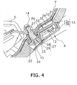
Fig. 4 is an enlarged cross-sectional view of a vicinity of a rotation output shaft of the indoor unit illustrated inFig. 1 . -
Fig. 5 is a perspective view for illustrating an interior structure of the driving unit for the components ofFig. 2 . -
- 1
- indoor unit
- 2
- bottom frame
- 2a
- airflow path formation part
- 5
- horizontal airflow direction louver
- 6
- driving unit
- 7
- airflow path
- 11
- motor
- 12
- link mechanism
- 13
- case
- 14
- rotation output shaft
- 15
- first through hole
- 21
- first engagement part
- 22
- grease
- 23
- second engagement part
- 24
- second through hole
- 27
- third engagement part
- 28
- convex part
- 29
- concave part
- 31
- air layer formation part
- 32
- air layer
- 33
- rib
- 34
- heat insulator
-
Fig. 1 is a vertical cross-sectional view for illustrating an interior structure of an indoor unit for an air conditioner according to an embodiment of the present invention. - An
indoor unit 1 is attached to a wall of an indoor space and the like. Theindoor unit 1 is mainly composed of abottom case 2, atop case 3, a main body section, horizontal airflowpath direction louvers 5 and adriving unit 6. Thebottom base 2 includes anairflow formation part 2a. The main body section includes an indoor heat exchanger 4 and across-flow fan 8. The horizontalairflow direction louvers 5 function as airflow direction change means. - The
bottom case 2 covers the bottom side and the back side of the main body section including the indoor heat exchanger 4, thecross-flow fan 8 and the like. Thetop case 3 is engaged with thebottom case 2 for covering the front side of the main body section. The airflowpath formation part 2a, forming aflow path 7, is formed above the upper surface of thebottom case 2. As illustrated inFig. 3 , the airflowpath formation part 2a includes a first throughhole 15 formed for allowing arotation output shaft 14 to reach the inside of theairflow path 7 therethrough. - The
top case 3 forms a front part of theindoor unit 1. Thetop case 3 is provided withsuction ports cross-flow fan 8. The indoor heat exchanger 4 is attached to theindoor unit 1 so as to surround thecross-flow fan 8 from the above, front and behind thereof. The indoor heat exchanger 4 is configured to conduct heat exchange between refrigerant passing through the interior of the indoor heat exchanger 4 and air to be sucked into thecross-flow fan 8 through thesuction ports cross-flow fan 8 is rotated. - Further, the
top case 3 is provided with a blow-outport 9. The blow-outport 9 is composed of an opening formed along an elongated direction (i.e., width direction) of theindoor unit 1. Airflow, generated by thecross-flow fan 8, is blown out of the blow-outport 9 to the indoor space. - The
airflow path 7 appropriately regulates airflow produced by thecross-flow fan 8, and guides it to the blow-outport 9. Theairflow path 7 is formed by the combination of thebottom case 2 and thetop case 3. A plurality of the horizontalairflow direction louvers 5 and a plurality ofhorizontal flaps 10 are provided in theairflow path 7. - As illustrated in
Fig. 2 , upper portions of a plurality of the horizontalairflow direction louvers 5 are attached to anattachment plate 20. Each of the horizontalairflow direction louvers 5 is thereby allowed to swing from side to side. Theattachment plate 20 is fixed to thebottom case 2. - Further, a plurality of the horizontal
airflow direction louvers 5 are coupled to therotation output shaft 14 through coupling pins 19, acoupling rod 17, acoupling pin 18 and anarm 16 for swinging from side to side by means of rotation drive force of therotation output shaft 14 of thedriving unit 6. Specifically, a plurality of the horizontalairflow direction louvers 5 is coupled to thecommon coupling rod 17 through thecoupling pin 19. Each of the horizontalairflow direction louvers 5 is coupled to thecoupling rod 17 for rotating about thecoupling pin 19. Thecoupling rod 17 is coupled to thearm 16 through thecoupling pin 18 while thearm 16 is fixed to therotation output shaft 14. Thecoupling rod 17 is coupled to thearm 16 for rotating around thecoupling pin 18. - The horizontal flaps 10 are configured to guide airflow to be blown out to the indoor space up and down. The horizontal flaps 10 are disposed in a vicinity of the blow-out
port 9. The horizontal flaps 10 are rectangular-shaped plate members elongated in an elongated direction of the blow-outport 9. Each of thehorizontal flaps 10 is allowed to rotate about an axis parallel to the elongated of the blow-outport 9. The horizontal flaps 10 are rotationally driven by a flap motor (not illustrated in the figure). Accordingly, thehorizontal flaps 10 are capable of guiding airflow up and down, and are also capable of closing the blow-outport 9. - As illustrated in
Figs. 3 to 5 , the drivingunit 6 includes amotor 11, alink mechanism 12, acase 13, and therotation output shaft 14. Thelink mechanism 12 is a mechanical component for transmitting power of themotor 11. Thecase 13 covers themotor 11 and thelink mechanism 12. Therotation output shaft 14 is configured to output power of themotor 11, which is transmitted through thelink mechanism 12, to the outside thecase 13. - The
motor 11 is composed of a stepping motor. Themotor 11 is capable of selecting a direction of rotation (either a clockwise direction or a counter-clockwise direction) and an angle of rotation corresponding to an input signal, and is capable of transmitting rotation drive force to thelink mechanism 12 based on the selected direction and angle of rotation. - The
link mechanism 12 is configured to transmit the rotation drive force of themotor 11 to therotation output shaft 14. Thelink mechanism 12 is composed of afirst arm 12a, acoupling rod 12b, acoupling pin 12c, asecond arm 12d and acoupling pin 12e. Thefirst arm 12a is coupled to a drivingshaft 11a of themotor 11. Thecoupling pin 12c couples thefirst arm 12a and thecoupling rod 12b for allowing them to couple rotatably. Thesecond arm 12d is coupled to therotation output shaft 14. Thecoupling pin 12e couples thecoupling rod 12b and thesecond arm 12d for allowing them to couple rotatably. - The
case 13 is composed of acase body 13a opened downward and abottom cover 13b. - As illustrated in
Fig. 4 , a blocking structure is formed in a periphery of the first throughhole 15 formed in the airflowpath formation part 2a of thebottom case 2. The blocking structure is configured to block communication between theairflow path 7 and the interior of thedriving unit 6. The blocking structure according to the present embodiment includes three engagement parts: afirst engagement part 21; asecond engagement part 23; and athird engagement part 27. - The
first engagement part 21 is formed by engagement between therotation output shaft 14 and the first throughhole 15 formed in the airflowpath formation part 2a of thebottom case 2. - The
first engagement part 21 further includesgrease 22 as sealing material applied between therotation output shaft 14 and the inner peripheral surface of the first throughhole 15. With thegrease 22, it is possible to further effectively enhance an effect for preventing conditioned air from leaking from the first throughhole 15. With thegrease 22, and also, it is possible to enhance lubrication of therotation output shaft 14. - The
second engagement part 23 is formed by engagement between therotation output shaft 14 and a second throughhole 24 formed in thecase 13. - The
third engagement part 27 is formed by engagement between aconvex part 28 and aconcave part 29. Theconvex part 28 is formed in a periphery of the first throughhole 15 formed in the airflowpath formation part 2a of thebottom case 2. Theconcave part 29 is formed in thecase 13. - The
indoor unit 1 further includes an airlayer formation part 31 for forming air layers 32 on a surface of thecase 13 opposing to the airflowpath formation part 2a. - The air
layer formation part 31 includes a plurality ofribs 33. Air layers 32 are formed between adjacent tworibs 33. - With air layers 32 thus formed on the upper surface of the
case 13, it is possible to block heat transfer between theair path 7 and the interior of thecase 13. - As illustrated in
Fig. 3 , theindoor unit 1 further includes aheat insulator 34 disposed between the airflowpath information part 2a of thebottom case 2 and thecase 13 of thedriving unit 6. Theheat insulator 34 is manufactured with sheet material having thermal insulation property. Theheat insulator 34 is disposed for covering a part of the upper surface of thecase 13, in which the airlayer formation part 31 is formed. Note that anopening 34a is formed in theheat insulator 34, and a position of theopening 34a corresponds to a position of therotation output shaft 14 and theconcave part 29 of thedriving unit 6. Accordingly, therotation output shaft 14 is allowed to be engaged with the first throughhole 15 of thebottom case 2 while theconcave part 29 is allowed to be engaged with theconvex part 28 of the bottom case 2 (seeFig. 4 ). -
- (1) In the
indoor unit 1 according to the present embodiment, the blocking structure (i.e., thefirst engagement part 21, thesecond engagement part 23 and the third engagement part 27) is formed for blocking communication between theairflow path 7 and the interior of thedriving unit 6. Therefore, it is possible to prevent occurrence of condensation in themotor 11 and the mechanical components (e.g., the link mechanism 12) due to leakage of conditioned air from theairflow path 7 to thedriving unit 6 for the horizontalairflow direction louvers 5 - (2) In the
indoor unit 1 according to the present embodiment, the blocking structure includes thefirst engagement part 21 formed by the engagement between therotation output shaft 14 and the first throughhole 15 formed in the airflowpath formation part 2a. Accordingly, with the engagement between therotation output shaft 14 and the first throughhole 15 formed in the airflowpath formation part 2a, it is possible to prevent prevent leakage of conditioned air. - (3) In the
indoor unit 1 according to the present embodiment, thefirst engagement part 21 further includes thegrease 22 as the sealing material applied between therotation output shaft 14 and the inner peripheral surface of the first throughhole 15. Accordingly, air tightness in thefirst engagement part 21 is further enhanced. Consequently, it is possible to prevent enhance a leakage prevention effect for conditioned air. - (4) In the
indoor unit 1 according to the present embodiment, thegrease 22 is used as the sealing material. Accordingly, it is possible to prevent enhance a leakage prevention effect for conditioned air and is possible to simultaneously enhance lubrication of therotation output shaft 14. - (5) In the
indoor unit 1 according to the present embodiment, the blocking structure includes thesecond engagement part 23 formed by the engagement between therotation output shaft 14 and the second throughhole 24 formed in thecase 13. Accordingly, it is possible to block leakage of conditioned air with the engagement between therotation output shaft 14 and the second throughhole 24 formed in thecase 13. - (6) In the
indoor unit 1 according to the present embodiment, the blocking structure includes thethird engagement part 27 formed by the engagement between theconvex part 28 formed in a periphery of the first throughhole 15 formed in the airflowpath formation part 2a and theconcave part 29 formed in thecase 13. Therefore, the engagement between theconvex part 28 of the airflowpath formation part 2a and theconcave part 29 of thecase 13 enhances adhesiveness between therotation output shaft 14 and the inner peripheral surface of the first throughhole 15. Consequently, it is possible to further enhance a leakage prevention effect for conditioned air. - (7) The
indoor unit 1 according to the present embodiment further includes the airlayer formation part 31 for forming air layers 32 on the surface of thecase 13 opposing to the airflowpath formation part 2a. Accordingly, the air layers 32 block heat transfer between theairflow path 7 and the interior of thecase 13. Consequently, it is possible to prevent occurrence of condensation due to temperature reduction of air in the interior of thecase 13. - (8) In the
indoor unit 1 according to the present embodiment, air layers 32, formed between adjacent tworibs 33, block heat transfer between theairflow path 7 and the interior of thecase 13. Accordingly, it is possible to prevent occurrence of condensation due to temperature reduction of air in the interior of thecase 13. - (9) In the
indoor unit 1 according to the present embodiment, theheat insulator 34, disposed between the airflowpath formation part 2a and thecase 13, blocks heat transfer between theairflow path 7 and the interior of thecase 13. Accordingly, it is possible to prevent occurrence of condensation due to temperature reduction of air in the interior of thecase 13. -
- (A) The aforementioned embodiment adopts the horizontal
airflow direction louvers 5 as the airflow direction change means. However, the present invention is not limited to this. For example, excluding the horizontal airflow direction louvers, means for changing airflow direction in the vertical direction (e.g., the horizontal flap 10) may be used as the airflow direction change means of the present invention. - (B) The aforementioned embodiment adopts the airflow
path formation part 2a of thebottom case 2 as an airflow path formation member for forming theairflow path 7. However, the present invention is not limited to this. For example, a member, separately provided from thebottom case 2, may be used as an airflow path formation member. - It is possible to apply the present invention to an indoor unit for an air co nditioner, provided with a motor for driving horizontal airflow direction louvers.
Claims (9)
- An indoor unit (1) for an air conditioner, comprising:an airflow path formation member (2a) for forming an airflow path (7);airflow direction change means (5) being disposed inside the airflow path (7), the airflow direction change means (5) being configured to change an airflow direction of a conditioned air to be blown out to an indoor space; anda driving unit (6) being disposed outside the airflow path (7), the driving unit (6) being configured to drive the airflow direction change means (5),wherein the driving unit (6) includes a motor (11), a mechanical component (12) for transmitting power of the motor (11), a case (13) for covering the motor (11) and the mechanical component (12), and a rotation output shaft (14) for outputting power of the motor (11) to the outside of the case (13) after receiving transmission of the power of the motor (11) through the mechanical component (12),
wherein the airflow path formation member (2a) includes a first through hole (15) formed for allowing the rotation output shaft (14) to reach the inside of the airflow path (7) therethrough, and
wherein a periphery of the first through hole (15) includes a blocking structure for blocking communication between the airflow path (7) and the interior of the driving unit (6). - The indoor unit (1) according to claim 1, wherein the blocking structure includes a first engagement part (21) formed by engagement of the rotation output shaft (14) and the first through hole (15) formed in the airflow path formation member (2a).
- The indoor unit (1) according to claim 2, wherein the first engagement part (21) further includes sealing material applied between the rotation output shaft (14) and the inner peripheral surface of the first through hole (15).
- The indoor unit (1) according to claim 3, wherein the sealing material is grease (22).
- The indoor unit (1) according to one of claims 1 to 4, wherein the blocking structure includes a second engagement part (23) formed by engagement between the rotation output shaft (14) and a second through hole (24) formed in the case (13).
- The indoor unit (1) according to claim 2, wherein the blocking structure includes a third engagement part (27) formed by engagement between a convex part (28) formed in a periphery of the first through hole (15) formed in the airflow path formation member (2a) and a concave part (29) formed in the case (13).
- The indoor unit (1) according to one of claims 1 to 6, further comprising an air layer formation part (31) for forming an air layer (32) on a surface of the case (13) opposing to the airflow path formation member (2a).
- The indoor unit (1) according to claim 7,
wherein the air layer formation part (31) includes a plurality of ribs (33), and
wherein the air layer (32) is formed between adjacent two ribs (33). - The indoor unit (1) according to one of claims 1 to 8, further comprising a heat insulator (34) disposed between the airflow path formation member (2a) and the case (13).
Applications Claiming Priority (1)
| Application Number | Priority Date | Filing Date | Title |
|---|---|---|---|
| PCT/JP2006/324207 WO2008068838A1 (en) | 2006-12-05 | 2006-12-05 | Indoor unit for air conditioner |
Publications (2)
| Publication Number | Publication Date |
|---|---|
| EP2093512A1 true EP2093512A1 (en) | 2009-08-26 |
| EP2093512A4 EP2093512A4 (en) | 2013-12-18 |
Family
ID=39491758
Family Applications (1)
| Application Number | Title | Priority Date | Filing Date |
|---|---|---|---|
| EP06833962.1A Withdrawn EP2093512A4 (en) | 2006-12-05 | 2006-12-05 | INDOOR UNIT FOR AIR CONDITIONING |
Country Status (4)
| Country | Link |
|---|---|
| EP (1) | EP2093512A4 (en) |
| CN (1) | CN101542210B (en) |
| AU (1) | AU2006351545B2 (en) |
| WO (1) | WO2008068838A1 (en) |
Families Citing this family (5)
| Publication number | Priority date | Publication date | Assignee | Title |
|---|---|---|---|---|
| JP5062115B2 (en) * | 2008-09-09 | 2012-10-31 | ダイキン工業株式会社 | Air conditioner indoor unit |
| JP2013088074A (en) * | 2011-10-20 | 2013-05-13 | Panasonic Corp | Air conditioner |
| CN105571102B (en) * | 2016-02-29 | 2019-03-26 | 珠海格力电器股份有限公司 | Air conditioner indoor unit shell, air conditioner indoor unit and air conditioner |
| CN110500655A (en) * | 2019-08-23 | 2019-11-26 | Tcl空调器(中山)有限公司 | Hanging air conditioner |
| JP7284686B2 (en) * | 2019-10-30 | 2023-05-31 | 日立グローバルライフソリューションズ株式会社 | refrigerator |
Family Cites Families (19)
| Publication number | Priority date | Publication date | Assignee | Title |
|---|---|---|---|---|
| JPH0336449Y2 (en) * | 1985-09-04 | 1991-08-01 | ||
| JPH047453Y2 (en) * | 1988-01-29 | 1992-02-27 | ||
| JPH06147526A (en) * | 1992-11-16 | 1994-05-27 | Matsushita Electric Ind Co Ltd | Air conditioner |
| JPH06201148A (en) * | 1992-12-28 | 1994-07-19 | Inoac Corp | Cover panel for ceiling outlet of air-conditioning apparatus |
| JPH07309212A (en) * | 1994-05-17 | 1995-11-28 | Nissan Motor Co Ltd | Ball joint structure |
| JP3635499B2 (en) * | 1994-06-30 | 2005-04-06 | オリンパス株式会社 | Work holding device |
| JPH10205801A (en) * | 1997-01-24 | 1998-08-04 | Matsushita Electric Ind Co Ltd | Manufacturing method of blower circuit insulation device for air conditioner |
| JP3765357B2 (en) * | 1997-06-20 | 2006-04-12 | 株式会社富士通ゼネラル | Air conditioner |
| JPH1194344A (en) * | 1997-09-19 | 1999-04-09 | Fujitsu General Ltd | Air conditioner |
| JP3896199B2 (en) * | 1997-10-07 | 2007-03-22 | 松下電器産業株式会社 | Louver mechanism and louver |
| JPH11159791A (en) * | 1997-11-28 | 1999-06-15 | Matsushita Electric Ind Co Ltd | Insulation equipment for air conditioners |
| JPH11237112A (en) * | 1998-02-24 | 1999-08-31 | Fujitsu General Ltd | Air conditioner |
| JP2000009343A (en) * | 1998-06-19 | 2000-01-14 | Fujitsu General Ltd | Air conditioner |
| US6210269B1 (en) * | 1998-06-22 | 2001-04-03 | Carrier Corporation | Oscillating drive for air flow discharge |
| JP3011708B1 (en) * | 1998-12-14 | 2000-02-21 | 松下電器産業株式会社 | Wind direction control method for air conditioner |
| JP3919993B2 (en) * | 2000-01-11 | 2007-05-30 | 松下電器産業株式会社 | Louver mechanism |
| JP2001289460A (en) * | 2000-04-05 | 2001-10-19 | Hitachi Ltd | Decorative panel for air conditioner |
| JP3929322B2 (en) * | 2002-02-15 | 2007-06-13 | 株式会社ニフコ | Air outlet adjustment device |
| JP2005140460A (en) | 2003-11-10 | 2005-06-02 | Mitsubishi Electric Corp | Air conditioner indoor unit |
-
2006
- 2006-12-05 WO PCT/JP2006/324207 patent/WO2008068838A1/en not_active Ceased
- 2006-12-05 AU AU2006351545A patent/AU2006351545B2/en not_active Ceased
- 2006-12-05 EP EP06833962.1A patent/EP2093512A4/en not_active Withdrawn
- 2006-12-05 CN CN2006800564949A patent/CN101542210B/en not_active Expired - Fee Related
Also Published As
| Publication number | Publication date |
|---|---|
| AU2006351545A1 (en) | 2008-06-12 |
| CN101542210B (en) | 2011-06-08 |
| AU2006351545B2 (en) | 2010-11-25 |
| EP2093512A4 (en) | 2013-12-18 |
| WO2008068838A1 (en) | 2008-06-12 |
| CN101542210A (en) | 2009-09-23 |
Similar Documents
| Publication | Publication Date | Title |
|---|---|---|
| US8511108B2 (en) | Air conditioning unit | |
| US12264825B2 (en) | Air guiding device, air conditioner indoor unit and air-conditioning system with air guiding part and flow straightening grid | |
| US20110232981A1 (en) | Movable grille shutter for vehicle | |
| CN105765315B (en) | Indoor unit | |
| CN116697577A (en) | Driving mechanism for air conditioner air deflector and air conditioner | |
| AU2006351545B2 (en) | Indoor unit for air conditioner | |
| AU2006333863B2 (en) | Indoor unit of air conditioner | |
| CN111735188B (en) | Air outlet device and mobile air conditioner | |
| JP4013976B2 (en) | Air conditioner indoor unit | |
| JP5045643B2 (en) | Blower, battery cooling device including the same, and vehicle air conditioner | |
| KR101040892B1 (en) | Air blower for car air conditioner | |
| CN212299360U (en) | Air outlet device and mobile air conditioner | |
| KR100873902B1 (en) | Air conditioner | |
| KR101474821B1 (en) | Vehicle ventilation device | |
| KR100760198B1 (en) | Air conditioner | |
| WO2007123166A1 (en) | Air conditioner | |
| CN119532828A (en) | Air Conditioner | |
| CN223596181U (en) | air conditioner | |
| JP2009179120A (en) | Rotary door device | |
| CN213019913U (en) | Air conditioner and its casing | |
| CN216977129U (en) | Air conditioner and indoor unit thereof | |
| CN110966700B (en) | Baffle for ventilation device and ventilation device | |
| KR20100053100A (en) | Air conditioner | |
| JP2004131032A (en) | Air blow part structure | |
| JP6684189B2 (en) | Vehicle air conditioner |
Legal Events
| Date | Code | Title | Description |
|---|---|---|---|
| PUAI | Public reference made under article 153(3) epc to a published international application that has entered the european phase |
Free format text: ORIGINAL CODE: 0009012 |
|
| 17P | Request for examination filed |
Effective date: 20090624 |
|
| AK | Designated contracting states |
Kind code of ref document: A1 Designated state(s): AT BE BG CH CY CZ DE DK EE ES FI FR GB GR HU IE IS IT LI LT LU LV MC NL PL PT RO SE SI SK TR |
|
| DAX | Request for extension of the european patent (deleted) | ||
| A4 | Supplementary search report drawn up and despatched |
Effective date: 20131115 |
|
| RIC1 | Information provided on ipc code assigned before grant |
Ipc: F24F 1/00 20110101ALI20131111BHEP Ipc: F24F 13/15 20060101AFI20131111BHEP Ipc: F24F 13/14 20060101ALI20131111BHEP Ipc: F24F 13/22 20060101ALI20131111BHEP |
|
| STAA | Information on the status of an ep patent application or granted ep patent |
Free format text: STATUS: THE APPLICATION IS DEEMED TO BE WITHDRAWN |
|
| 18D | Application deemed to be withdrawn |
Effective date: 20140614 |