EP2093499A1 - Cooking oven with quick guide - Google Patents
Cooking oven with quick guide Download PDFInfo
- Publication number
- EP2093499A1 EP2093499A1 EP08003218A EP08003218A EP2093499A1 EP 2093499 A1 EP2093499 A1 EP 2093499A1 EP 08003218 A EP08003218 A EP 08003218A EP 08003218 A EP08003218 A EP 08003218A EP 2093499 A1 EP2093499 A1 EP 2093499A1
- Authority
- EP
- European Patent Office
- Prior art keywords
- door
- cooking
- frame portion
- quick guide
- cooking oven
- Prior art date
- Legal status (The legal status is an assumption and is not a legal conclusion. Google has not performed a legal analysis and makes no representation as to the accuracy of the status listed.)
- Withdrawn
Links
- 238000010411 cooking Methods 0.000 title claims abstract description 51
- 239000000758 substrate Substances 0.000 claims description 3
- 235000013305 food Nutrition 0.000 description 4
- 230000003287 optical effect Effects 0.000 description 4
- 238000005516 engineering process Methods 0.000 description 2
- 238000012986 modification Methods 0.000 description 2
- 230000004048 modification Effects 0.000 description 2
- 241000251468 Actinopterygii Species 0.000 description 1
- 238000004140 cleaning Methods 0.000 description 1
- 230000001419 dependent effect Effects 0.000 description 1
- 238000012423 maintenance Methods 0.000 description 1
- 238000004519 manufacturing process Methods 0.000 description 1
- 235000013550 pizza Nutrition 0.000 description 1
Images

Classifications
-
- F—MECHANICAL ENGINEERING; LIGHTING; HEATING; WEAPONS; BLASTING
- F24—HEATING; RANGES; VENTILATING
- F24C—DOMESTIC STOVES OR RANGES ; DETAILS OF DOMESTIC STOVES OR RANGES, OF GENERAL APPLICATION
- F24C15/00—Details
- F24C15/16—Shelves, racks or trays inside ovens; Supports therefor
- F24C15/162—Co-operating with a door, e.g. operated by the door
Definitions
- the present invention relates to a cooking oven comprising a cabinet defining an oven cavity with a charging opening for charging the oven cavity with foodstuff to be cooked; and a drawer-like door for optionally opening and closing said charging opening in a substantially horizontal direction, said door including at least one wall and a door frame surrounding said wall and having an upper frame portion, a lower frame portion and two side frame portions.
- Cooking ovens of the above-mentioned type are known in several configurations.
- cooking ovens are normally delivered with an operating manual.
- Such an operating manual normally contains information about the temperature; the mode; e.g. top heat, bottom heat, air circulation; the baking tray level within the oven; etc.; which should be used in a special cooking situation, e.g. when cooking fish, a roast, when making an au gratin, a pizza, etc, in order to achieve an optimal cooking result. Accordingly, the user can get a general idea about the way to operate the cooking oven when studying the operating manual.
- DE-A-101 25 247 discloses a cooking oven comprising a cabinet defining an oven cavity with a charging opening for charging the oven cavity with foodstuff to be cooked; and a door for optionally opening and closing said charging opening; a plurality of baking ray holders arranged on different levels within the oven cavity for receiving baking trays, baking grids, etc.; an optical identification mark for each baking tray holder, said optical identification marks being positioned next to the corresponding baking tray holders in the form of a signal light or the like; and a control panel for choosing a baking program, said control panel being arranged above the door and connected to a control device. According to such an arrangement, the user can choose a cooking program according to the intended cooking situation by means of the control panel.
- the control device will automatically actuate one or more of the optical identification marks assigned to the chosen cooking program to signalize the user where the baking tray should be placed in order to receive an optimal cooking result.
- this arrangement is very comfortable and effective.
- it is also very expensive to manufacture.
- the control device or the optical identifications marks may get damaged. Accordingly, a maintenance of these components may be necessary.
- Another solution is to provide a cooking oven with a quick guide, which contains information about the handling of the cooking oven with respect to the most frequent cooking situations.
- Such quick guides are normally positioned - in form of an impression, a label, etc. - at the inner side of the door, so they cannot be seen from the outside in order to not disturb the outer appearance of the cooking oven.
- This arrangement of the quick guide is effective, when the door is pivoted at the cabinet, because the quick guide can be easily studied by the user in the opened state of the door.
- the inner side of the door wall is - even in the opened state of the door - hardly visible for the user.
- the present invention provides a cooking oven comprising a cabinet defining an oven cavity with a charging opening (or feeding opening) for charging (or feeding) the oven cavity with foodstuff to be cooked; a drawer-like door for optionally opening and closing said charging opening in a substantially horizontal direction, said door including at least one wall and a door frame surrounding said at least one wall and having an upper frame portion, a lower frame portion and two side frame portions; and a quick guide suggesting to the user adequate handling of the cooking oven with respect to different cooking situations.
- the cooking oven of the present invention is characterized in that said quick guide is arranged at the upper frame portion of the door frame. Accordingly, the user can easily study the quick guide in the opened state of the door, i.e. in the state, when he or she intends to use the cooking oven. On the other hand the quick guide is usually not visible in the closed state of the door, such that it does not derogate the outer appearance of the oven.
- the quick guide is arranged directly on the upper frame portion.
- the quick guide is arranged at a substrate, e.g. a plate or tag, which is in turn fixed to the upper frame portion.
- the quick guide may be provided in printed and/or in graved form. When printed, the used colour should be temperature and cleaning resistant.
- the cooking oven comprises a plurality of baking tray holders provided on different levels within the oven cavity or at the inner side of the at least one wall of the door, whereas each level is identified by a specific identification mark arranged at a position, which is well visible for the user, e.g., a position directly adjacent the baking tray holder.
- the quick guide comprises information, which assigns specific cooking situations to specific identification marks. Accordingly, the user can take from the quick guide, which specific baking tray holder level should be used for a specific cooking situation in order to receive an optimal baking result.
- the specific identification marks are numbers, e.g. from 1 to 5, or letters, e.g. from A to E, if five baking tray holders are provided.
- the quantity of baking tray holders is not limited to five.
- Figure 1 is a perspective rear view of an embodiment of a door 10 of a cooking oven according to the present invention
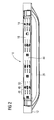
- figure 2 is a top view of the door 10
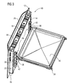
- figure 3 is a perspective rear view of the door 10 with a baking tray attached thereto.
- the door 10 comprises a front wall 12, a back wall 14 and a frame 16 surrounding the walls 12 and 14.
- the frame 16 includes an upper frame portion 18, a lower frame portion 20 and two side frame portions 22 and 24, which are fixed to each other. Furthermore, a handle 26 for opening and closing the door 10 is fixed to the upper portion of the front wall 12.
- the door 10 is one of the drawer-like type, i.e. the door 10 is arranged at a cooking oven in such a manner, that it opens an closes the charging opening of the cooking oven by means of movements in a substantially linear and horizontal direction.
- the door 10 may be, e.g., attached at the free ends of two sliding bars, which are received in two corresponding guiding rails arranged beneath the oven cavity (not shown in the figures). Accordingly, the door 10 may perform a horizontal back and forth movement together with the sliding bars, which slide along the guiding rails.
- Such drawer-like doors are basically known in the prior art (see, e.g., EP-A-0 443 329 ) and are not described in more detail herein.
- a baking tray holder 28 which comprises two rails 30 secured to the back wall 14 of the door 10.
- the rails 30 each have an essentially U-shaped cross-section and extend in a vertical direction in parallel to each other.
- Each rail 30 contains a plurality of longish holes 32, which are aligned vertically.
- Each hole 32 of one rail 30 is positioned on the same level as one hole 32 of the other rail 30, such that pairs of holes 32 on different levels are formed.
- each hole 32 is formed of a longish, slit-like lower hole-section 34 and an upper hole-section 36, which broadens in the upward direction starting form the lower hole-section 34.
- the pairs of holes 32 arranged on a common level are each adapted to receive a hook-like fixing means 38 of a supporting frame 39, which performs the task of supporting a baking tray 40, as it is shown in figure 3 , or another component, on which food items to be cooked may be placed.
- the fixing means 38 can be provided directly on baking trays, baking grids, etc., such that the supporting frame may be omitted.
- Each level, on which a baking tray may be arranged, is marked by means of special identification marks 42 being arranged at the outer surfaces of the rails 30 facing to the sides of the door 10.
- the identification marks 42 serve to identify the different levels to the user and are provided in the form of numbers from 1 to 5, whereas 1 identifies the lowermost level and 5 identifies the uppermost level.
- other identification marks may be uses instead of the numbers 1 to 5, e.g. the letters A to E or the like.
- the identification marks are graved. However, they also can be provided in a different way, e.g. as printed numbers or the like.
- the door 10 comprises a quick guide 44 arranged at the upper frame portion 18 of the frame 16.
- the quick guide 44 contains information suggesting to the user an adequate handling of the cooking oven with respect to different cooking situations in order to achieve an optimal cooking result.
- this information is given by means of icons 46 representing the kind of food to be cooked, by means of temperature information 48, i.e. information about the temperature range within which the food represented by a specific icon should be cooked, and by means of level information 50 representing the identification mark 42 and hence the level on which the food represented by a specific icon should be arranged at the baking tray holder 28.
- the quick guide 44 is printed on the upper frame portion 18 of the frame 16.
- the quick guide 44 may be provided in another form, e.g. in graved form or arranged at a substrate (not shown), e.g. a plate or tag, which in turn is fixed to the upper frame portion 18, etc.
- the quick guide 44 By positioning the quick guide 44 on the upper frame portion 18 of the frame 16 of the door 10, the user can easily read the instructions of the quick guide 44 when opening the drawer-like door 10 of the cooking oven. Moreover, the quick guide 44 is hidden, when the door 10 is in its closed state. Accordingly, the quick guide 44 does not disturb the outer appearance of the oven.
Landscapes
- Engineering & Computer Science (AREA)
- Chemical & Material Sciences (AREA)
- Combustion & Propulsion (AREA)
- Mechanical Engineering (AREA)
- General Engineering & Computer Science (AREA)
- Baking, Grill, Roasting (AREA)
Abstract
Description
- The present invention relates to a cooking oven comprising a cabinet defining an oven cavity with a charging opening for charging the oven cavity with foodstuff to be cooked; and a drawer-like door for optionally opening and closing said charging opening in a substantially horizontal direction, said door including at least one wall and a door frame surrounding said wall and having an upper frame portion, a lower frame portion and two side frame portions.
- Cooking ovens of the above-mentioned type are known in several configurations.
- In order to teach the user about the handling of the cooking oven in different cooking situations, cooking ovens are normally delivered with an operating manual. Such an operating manual normally contains information about the temperature; the mode; e.g. top heat, bottom heat, air circulation; the baking tray level within the oven; etc.; which should be used in a special cooking situation, e.g. when cooking fish, a roast, when making an au gratin, a pizza, etc, in order to achieve an optimal cooking result. Accordingly, the user can get a general idea about the way to operate the cooking oven when studying the operating manual.
- However, due to the detailedness of such operating manuals it is very uncommon, that a user studies the manual each time before cooking. This leads to an incorrect handling of the cooking oven and hence to suboptimal cooking results.
- In order to overcome this drawback,
DE-A-101 25 247 discloses a cooking oven comprising a cabinet defining an oven cavity with a charging opening for charging the oven cavity with foodstuff to be cooked; and a door for optionally opening and closing said charging opening; a plurality of baking ray holders arranged on different levels within the oven cavity for receiving baking trays, baking grids, etc.; an optical identification mark for each baking tray holder, said optical identification marks being positioned next to the corresponding baking tray holders in the form of a signal light or the like; and a control panel for choosing a baking program, said control panel being arranged above the door and connected to a control device. According to such an arrangement, the user can choose a cooking program according to the intended cooking situation by means of the control panel. As soon as the cooking program is chosen, the control device will automatically actuate one or more of the optical identification marks assigned to the chosen cooking program to signalize the user where the baking tray should be placed in order to receive an optimal cooking result. In this regard, this arrangement is very comfortable and effective. However, it is also very expensive to manufacture. Moreover, the control device or the optical identifications marks may get damaged. Accordingly, a maintenance of these components may be necessary. - Another solution is to provide a cooking oven with a quick guide, which contains information about the handling of the cooking oven with respect to the most frequent cooking situations. Such quick guides are normally positioned - in form of an impression, a label, etc. - at the inner side of the door, so they cannot be seen from the outside in order to not disturb the outer appearance of the cooking oven. This arrangement of the quick guide is effective, when the door is pivoted at the cabinet, because the quick guide can be easily studied by the user in the opened state of the door.
- However, when the door is a drawer-like door, the inner side of the door wall is - even in the opened state of the door - hardly visible for the user.
- Starting from the above mentioned prior art technology it is an object of the present invention to provide a cooking oven of the mentioned type, which has an alternative configuration in order to eliminate the foregoing drawbacks.
- This object is solved by providing a cooking oven according to
claim 1. The dependent claims refer to individual embodiments of the present invention. - The present invention provides a cooking oven comprising a cabinet defining an oven cavity with a charging opening (or feeding opening) for charging (or feeding) the oven cavity with foodstuff to be cooked; a drawer-like door for optionally opening and closing said charging opening in a substantially horizontal direction, said door including at least one wall and a door frame surrounding said at least one wall and having an upper frame portion, a lower frame portion and two side frame portions; and a quick guide suggesting to the user adequate handling of the cooking oven with respect to different cooking situations.
- The cooking oven of the present invention is characterized in that said quick guide is arranged at the upper frame portion of the door frame. Accordingly, the user can easily study the quick guide in the opened state of the door, i.e. in the state, when he or she intends to use the cooking oven. On the other hand the quick guide is usually not visible in the closed state of the door, such that it does not derogate the outer appearance of the oven.
- According to one aspect of the present invention, the quick guide is arranged directly on the upper frame portion.
- According to another aspect pf the present invention, the quick guide is arranged at a substrate, e.g. a plate or tag, which is in turn fixed to the upper frame portion.
- The quick guide may be provided in printed and/or in graved form. When printed, the used colour should be temperature and cleaning resistant.
- According to a preferred embodiment of the present invention, the cooking oven comprises a plurality of baking tray holders provided on different levels within the oven cavity or at the inner side of the at least one wall of the door, whereas each level is identified by a specific identification mark arranged at a position, which is well visible for the user, e.g., a position directly adjacent the baking tray holder. Moreover, the quick guide comprises information, which assigns specific cooking situations to specific identification marks. Accordingly, the user can take from the quick guide, which specific baking tray holder level should be used for a specific cooking situation in order to receive an optimal baking result.
- Preferably, the specific identification marks are numbers, e.g. from 1 to 5, or letters, e.g. from A to E, if five baking tray holders are provided. However, it should be noticed, that the quantity of baking tray holders is not limited to five.
- The detailed configuration, features and advantages of the present invention will become apparent in the course of the following description with reference to the accompanying drawings.
- Figure 1
- is a perspective rear view showing a door of a cooking oven according to an embodiment of the present invention;
- Figure 2
- is a top view of the door shown in
figure 1 ; and - Figure 3
- is a perspective rear view of the door shown in
figures 1 and2 , whereas a baking tray is fixed to the door. - Below, one embodiment of the present will be described with reference to the
figures 1 to 3 . In these figures, like parts or portions are denoted by like reference numerals. -
Figure 1 is a perspective rear view of an embodiment of adoor 10 of a cooking oven according to the present invention,figure 2 is a top view of thedoor 10, andfigure 3 is a perspective rear view of thedoor 10 with a baking tray attached thereto. - The
door 10 comprises afront wall 12, aback wall 14 and aframe 16 surrounding thewalls frame 16 includes anupper frame portion 18, alower frame portion 20 and twoside frame portions handle 26 for opening and closing thedoor 10 is fixed to the upper portion of thefront wall 12. - The
door 10 is one of the drawer-like type, i.e. thedoor 10 is arranged at a cooking oven in such a manner, that it opens an closes the charging opening of the cooking oven by means of movements in a substantially linear and horizontal direction. In this regard, thedoor 10 may be, e.g., attached at the free ends of two sliding bars, which are received in two corresponding guiding rails arranged beneath the oven cavity (not shown in the figures). Accordingly, thedoor 10 may perform a horizontal back and forth movement together with the sliding bars, which slide along the guiding rails. Such drawer-like doors are basically known in the prior art (see, e.g.,EP-A-0 443 329 ) and are not described in more detail herein. - A
baking tray holder 28 is provided, which comprises tworails 30 secured to theback wall 14 of thedoor 10. Therails 30 each have an essentially U-shaped cross-section and extend in a vertical direction in parallel to each other. Eachrail 30 contains a plurality oflongish holes 32, which are aligned vertically. Eachhole 32 of onerail 30 is positioned on the same level as onehole 32 of theother rail 30, such that pairs ofholes 32 on different levels are formed. Moreover, eachhole 32 is formed of a longish, slit-like lower hole-section 34 and an upper hole-section 36, which broadens in the upward direction starting form the lower hole-section 34. The pairs ofholes 32 arranged on a common level are each adapted to receive a hook-like fixing means 38 of a supportingframe 39, which performs the task of supporting abaking tray 40, as it is shown infigure 3 , or another component, on which food items to be cooked may be placed. However, it should be noticed, that the fixing means 38 can be provided directly on baking trays, baking grids, etc., such that the supporting frame may be omitted. - Each level, on which a baking tray may be arranged, is marked by means of
special identification marks 42 being arranged at the outer surfaces of therails 30 facing to the sides of thedoor 10. Theidentification marks 42 serve to identify the different levels to the user and are provided in the form of numbers from 1 to 5, whereas 1 identifies the lowermost level and 5 identifies the uppermost level. However, it should be noticed, that other identification marks may be uses instead of thenumbers 1 to 5, e.g. the letters A to E or the like. According to the present embodiment, the identification marks are graved. However, they also can be provided in a different way, e.g. as printed numbers or the like. - Moreover, the
door 10 comprises aquick guide 44 arranged at theupper frame portion 18 of theframe 16. Thequick guide 44 contains information suggesting to the user an adequate handling of the cooking oven with respect to different cooking situations in order to achieve an optimal cooking result. According to the present embodiment, this information is given by means oficons 46 representing the kind of food to be cooked, by means oftemperature information 48, i.e. information about the temperature range within which the food represented by a specific icon should be cooked, and by means oflevel information 50 representing theidentification mark 42 and hence the level on which the food represented by a specific icon should be arranged at thebaking tray holder 28. - According to the present embodiment, the
quick guide 44 is printed on theupper frame portion 18 of theframe 16. However, it should be noticed, that thequick guide 44 may be provided in another form, e.g. in graved form or arranged at a substrate (not shown), e.g. a plate or tag, which in turn is fixed to theupper frame portion 18, etc. - By positioning the
quick guide 44 on theupper frame portion 18 of theframe 16 of thedoor 10, the user can easily read the instructions of thequick guide 44 when opening the drawer-like door 10 of the cooking oven. Moreover, thequick guide 44 is hidden, when thedoor 10 is in its closed state. Accordingly, thequick guide 44 does not disturb the outer appearance of the oven. - Although only one exemplary embodiment of this invention has been described in detail above, those skilled in the art will readily appreciate that many modifications are possible with respect to the exemplary embodiments without materially departing from the novel teachings and advantages of this invention. Accordingly, all such modifications are intended to be included within the scope of this invention.
-
- 10
- door
- 12
- front wall
- 14
- back wall
- 16
- frame
- 18
- upper frame portion
- 20
- lower frame portion
- 22
- side frame portion
- 24
- side frame portion
- 26
- handle
- 28
- baking tray holder
- 30
- rail
- 32
- hole
- 34
- lower hole-section
- 36
- upper hole-section
- 38
- fixing means
- 39
- supporting frame
- 40
- baking tray
- 42
- identification mark
- 44
- quick guide
- 46
- icon
- 48
- temperature information
- 50
- level information
Claims (6)
- A cooking oven comprising a cabinet defining an oven cavity with a charging opening for charging the oven cavity with foodstuff to be cooked; a drawer-like door (10) being movable in a substantially horizontal direction for opening or closing said charging opening, said door (10) including at least one wall (12, 14) and a door frame (16) surrounding said at least one wall (12, 14) and having an upper frame portion (18), a lower frame portion (20) and two side frame portions (22, 24); and a list of cooking information or quick guide (44) suggesting to the user adequate handling of the cooking oven with respect to different cooking situations; characterized in that said quick guide (44) is arranged at the upper frame portion (18) of the door frame (16).
- A cooking oven according to claim 1, characterized in that the quick guide (44) is arranged directly on the upper frame portion (18).
- A cooking oven according to claim 2, characterized in that the quick guide (44) is printed and or graved on the upper frame portion (18).
- A cooking oven according to claim 1, characterized in that the quick guide (44) is arranged at a substrate which in turn is fixed to the upper frame portion (18).
- A cooking oven according to one of the foregoing claims, characterized in that a plurality of baking tray holders (28) is provided on different levels within the oven cavity or at the inner side of the at least one wall (14) of the door (10), whereas each level is identified by a specific identification mark (42) arranged at a position, which is well visible for the user; and in that the quick guide (44) comprises information (46, 48, 50), which assigns specific cooking situations to specific identification marks (42).
- A cooking oven according to claim 5, characterized in that the specific identification marks (42) are numbers (50) or letters.
Priority Applications (1)
| Application Number | Priority Date | Filing Date | Title |
|---|---|---|---|
| EP08003218A EP2093499A1 (en) | 2008-02-22 | 2008-02-22 | Cooking oven with quick guide |
Applications Claiming Priority (1)
| Application Number | Priority Date | Filing Date | Title |
|---|---|---|---|
| EP08003218A EP2093499A1 (en) | 2008-02-22 | 2008-02-22 | Cooking oven with quick guide |
Publications (1)
| Publication Number | Publication Date |
|---|---|
| EP2093499A1 true EP2093499A1 (en) | 2009-08-26 |
Family
ID=40140012
Family Applications (1)
| Application Number | Title | Priority Date | Filing Date |
|---|---|---|---|
| EP08003218A Withdrawn EP2093499A1 (en) | 2008-02-22 | 2008-02-22 | Cooking oven with quick guide |
Country Status (1)
| Country | Link |
|---|---|
| EP (1) | EP2093499A1 (en) |
Cited By (2)
| Publication number | Priority date | Publication date | Assignee | Title |
|---|---|---|---|---|
| DE102019200772A1 (en) * | 2019-01-23 | 2020-07-23 | BSH Hausgeräte GmbH | Cooking appliance with a specific identification feature on a front flange |
| EP3771867A1 (en) * | 2019-07-30 | 2021-02-03 | BSH Hausgeräte GmbH | An oven having a container extracting arrangement |
Citations (7)
| Publication number | Priority date | Publication date | Assignee | Title |
|---|---|---|---|---|
| JPS60240921A (en) * | 1984-05-15 | 1985-11-29 | Matsushita Electric Ind Co Ltd | Operating device for heating cooker |
| EP0443329A2 (en) | 1990-02-21 | 1991-08-28 | BOSCH-SIEMENS HAUSGERÄTE GmbH | Baking oven |
| DE4444316A1 (en) * | 1994-12-13 | 1996-06-20 | Bosch Siemens Hausgeraete | stove |
| DE10007923C1 (en) * | 2000-02-21 | 2001-10-31 | Aeg Hausgeraete Gmbh | Glass oven door has enamel paint instructions printed on outer surface of inside door panel adjoining outside door panel |
| DE10125247C1 (en) | 2001-05-23 | 2002-12-12 | Miele & Cie | Household appliance with a cooking space |
| DE10349315A1 (en) * | 2003-10-23 | 2005-05-25 | BSH Bosch und Siemens Hausgeräte GmbH | Baking oven with lifting bottom plate has support posts with level markings to control relative setting of baking trays |
| EP1835232A2 (en) * | 2006-03-16 | 2007-09-19 | Electrolux Home Products Corporation N.V. | Baking oven |
-
2008
- 2008-02-22 EP EP08003218A patent/EP2093499A1/en not_active Withdrawn
Patent Citations (7)
| Publication number | Priority date | Publication date | Assignee | Title |
|---|---|---|---|---|
| JPS60240921A (en) * | 1984-05-15 | 1985-11-29 | Matsushita Electric Ind Co Ltd | Operating device for heating cooker |
| EP0443329A2 (en) | 1990-02-21 | 1991-08-28 | BOSCH-SIEMENS HAUSGERÄTE GmbH | Baking oven |
| DE4444316A1 (en) * | 1994-12-13 | 1996-06-20 | Bosch Siemens Hausgeraete | stove |
| DE10007923C1 (en) * | 2000-02-21 | 2001-10-31 | Aeg Hausgeraete Gmbh | Glass oven door has enamel paint instructions printed on outer surface of inside door panel adjoining outside door panel |
| DE10125247C1 (en) | 2001-05-23 | 2002-12-12 | Miele & Cie | Household appliance with a cooking space |
| DE10349315A1 (en) * | 2003-10-23 | 2005-05-25 | BSH Bosch und Siemens Hausgeräte GmbH | Baking oven with lifting bottom plate has support posts with level markings to control relative setting of baking trays |
| EP1835232A2 (en) * | 2006-03-16 | 2007-09-19 | Electrolux Home Products Corporation N.V. | Baking oven |
Cited By (2)
| Publication number | Priority date | Publication date | Assignee | Title |
|---|---|---|---|---|
| DE102019200772A1 (en) * | 2019-01-23 | 2020-07-23 | BSH Hausgeräte GmbH | Cooking appliance with a specific identification feature on a front flange |
| EP3771867A1 (en) * | 2019-07-30 | 2021-02-03 | BSH Hausgeräte GmbH | An oven having a container extracting arrangement |
Similar Documents
| Publication | Publication Date | Title |
|---|---|---|
| EP2304322B1 (en) | Oven | |
| US20230408103A1 (en) | Household cooking appliance | |
| US9970663B2 (en) | Stove top having a cooking zone and a reduced symbol depiction in the cooking zone in a display unit and method for operating a stove top | |
| DE102010029197A1 (en) | Cooking device, particularly oven, comprises cooking chamber wall and cooking chamber which is limited with drawer levels, where detection unit is provided for detecting occupancy of drawer levels by component part | |
| EP3619472A1 (en) | Domestic appliance comprising illumination device for recessed grip | |
| WO2007047597A2 (en) | Food holding cabinet with removable tray covers | |
| US20140021835A1 (en) | Countertop Oven Accessories | |
| US20060131296A1 (en) | Electric oven | |
| US3717397A (en) | Universal self-leveling dispenser | |
| DE10125247C1 (en) | Household appliance with a cooking space | |
| EP2469190A1 (en) | A cooking hob including an upper part and a base part | |
| JP4802055B2 (en) | Cooker | |
| JP2016202428A (en) | Cooker | |
| EP2063186A2 (en) | Cooking oven with holding device for cooking good carrier | |
| USD511936S1 (en) | Oven door vent/handle assembly for a cooking appliance | |
| US20090293857A1 (en) | Domestic Appliance and a Cookable Product Holding Device Therefor | |
| JP5526815B2 (en) | Vending machine product sample display device | |
| KR0125712B1 (en) | Control device & control method of microwave oven | |
| EP2307808A1 (en) | Kitchen oven | |
| EP2226569A1 (en) | A cooking oven with at least one cooking chamber | |
| US10295193B2 (en) | Cooking appliance, in particular for domestic use | |
| ATE297531T1 (en) | OVEN FOR FOOD | |
| GB2254470A (en) | Presenting information on domestic appliances. | |
| KR100281485B1 (en) | Menu board | |
| CN115930532A (en) | Food receiving containers and household refrigeration appliances for air-conditioning units with front slats and sliders |
Legal Events
| Date | Code | Title | Description |
|---|---|---|---|
| PUAI | Public reference made under article 153(3) epc to a published international application that has entered the european phase |
Free format text: ORIGINAL CODE: 0009012 |
|
| AK | Designated contracting states |
Kind code of ref document: A1 Designated state(s): AT BE BG CH CY CZ DE DK EE ES FI FR GB GR HR HU IE IS IT LI LT LU LV MC MT NL NO PL PT RO SE SI SK TR |
|
| AX | Request for extension of the european patent |
Extension state: AL BA MK RS |
|
| 17P | Request for examination filed |
Effective date: 20091027 |
|
| AKX | Designation fees paid |
Designated state(s): AT BE BG CH CY CZ DE DK EE ES FI FR GB GR HR HU IE IS IT LI LT LU LV MC MT NL NO PL PT RO SE SI SK TR |
|
| RAP1 | Party data changed (applicant data changed or rights of an application transferred) |
Owner name: ELECTROLUX HOME PRODUCTS CORPORATION N.V. |
|
| RAP1 | Party data changed (applicant data changed or rights of an application transferred) |
Owner name: ELECTROLUX HOME PRODUCTS CORPORATION N.V. |
|
| STAA | Information on the status of an ep patent application or granted ep patent |
Free format text: STATUS: THE APPLICATION IS DEEMED TO BE WITHDRAWN |
|
| 18D | Application deemed to be withdrawn |
Effective date: 20160901 |