EP2093486A2 - Gas flow rate control valve - Google Patents
Gas flow rate control valve Download PDFInfo
- Publication number
- EP2093486A2 EP2093486A2 EP08014995A EP08014995A EP2093486A2 EP 2093486 A2 EP2093486 A2 EP 2093486A2 EP 08014995 A EP08014995 A EP 08014995A EP 08014995 A EP08014995 A EP 08014995A EP 2093486 A2 EP2093486 A2 EP 2093486A2
- Authority
- EP
- European Patent Office
- Prior art keywords
- gas flow
- flow rate
- rate control
- magnetic
- control valve
- Prior art date
- Legal status (The legal status is an assumption and is not a legal conclusion. Google has not performed a legal analysis and makes no representation as to the accuracy of the status listed.)
- Withdrawn
Links
Images


Classifications
-
- F—MECHANICAL ENGINEERING; LIGHTING; HEATING; WEAPONS; BLASTING
- F23—COMBUSTION APPARATUS; COMBUSTION PROCESSES
- F23N—REGULATING OR CONTROLLING COMBUSTION
- F23N5/00—Systems for controlling combustion
- F23N5/24—Preventing development of abnormal or undesired conditions, i.e. safety arrangements
- F23N5/245—Preventing development of abnormal or undesired conditions, i.e. safety arrangements using electrical or electromechanical means
-
- F—MECHANICAL ENGINEERING; LIGHTING; HEATING; WEAPONS; BLASTING
- F16—ENGINEERING ELEMENTS AND UNITS; GENERAL MEASURES FOR PRODUCING AND MAINTAINING EFFECTIVE FUNCTIONING OF MACHINES OR INSTALLATIONS; THERMAL INSULATION IN GENERAL
- F16K—VALVES; TAPS; COCKS; ACTUATING-FLOATS; DEVICES FOR VENTING OR AERATING
- F16K31/00—Actuating devices; Operating means; Releasing devices
- F16K31/02—Actuating devices; Operating means; Releasing devices electric; magnetic
- F16K31/06—Actuating devices; Operating means; Releasing devices electric; magnetic using a magnet, e.g. diaphragm valves, cutting off by means of a liquid
- F16K31/08—Actuating devices; Operating means; Releasing devices electric; magnetic using a magnet, e.g. diaphragm valves, cutting off by means of a liquid using a permanent magnet
- F16K31/082—Actuating devices; Operating means; Releasing devices electric; magnetic using a magnet, e.g. diaphragm valves, cutting off by means of a liquid using a permanent magnet using a electromagnet and a permanent magnet
-
- F—MECHANICAL ENGINEERING; LIGHTING; HEATING; WEAPONS; BLASTING
- F23—COMBUSTION APPARATUS; COMBUSTION PROCESSES
- F23N—REGULATING OR CONTROLLING COMBUSTION
- F23N1/00—Regulating fuel supply
- F23N1/005—Regulating fuel supply using electrical or electromechanical means
Definitions
- the present invention relates generally to gas equipments and more particularly, to a gas flow rate control valve for controlling the flow rate of a fuel gas accurately.
- Taiwan patent publication number M322516 discloses a gas flow rate control valve.
- the gas flow rate control valve comprises a rotary gas supply control disk and a fixed gas supply control disk.
- the rotary gas supply control disk has multiple gas flow rate control holes that have different diameters.
- the fixed gas supply control disk has a guide hole.
- the gas flow rate control is limited to the design of the gas flow rate control holes, i.e., the gas flow rate control holes allow regulation of the gas flow rate step by step, however they do not allow for linear gas flow rate control.
- This inconvenient gas flow rate control method cannot satisfy user's different demands.
- the supply of the fuel gas may be interrupted before alignment of the next gas flow rate control hole with the guide hole, resulting in flame failure. Therefore, this design of gas flow rate control valve is not safe in use.
- the present invention has been accomplished under the circumstances in view. It is the main objective of the present invention to provide a gas flow rate control valve, which directly controls adjustment of the open cross-sectional area of the gas flow passage subject to the amount of displacement of a magnetic column, achieving accurate gas flow rate control.
- the gas flow rate control valve comprises: a lower valve block, which defines a gas flow passage for the passing of a fuel gas, an upper valve block, which is fixedly mounted on a top side of the lower valve block and includes a tube disposed in communication with the gas flow passage, and a solenoid coil assembly surrounding the tube for generating a magnetic field, a magnetic column, which includes a magnetic portion inserted into the tube and axially movable in the tube by the magnetic field generated by the solenoid coil assembly, and a stopper movable with the magnetic portion to change an open cross-sectional area of the gas flow passage so as to further control a flow rate of the fuel gas passing through the gas flow passage, and a spring member provided at one of top and bottom sides of the magnetic column to keep the magnetic column in balance and to provide a return force to the magnetic column after a displacement of the magnetic column.
- the open cross-sectional area of the gas flow passage is relatively adjusted, achieving accurate gas flow rate control.
- the linear relationship between the magnetic field generated by the solenoid coil assembly and the amount of displacement of the magnetic column assures accurate gas flow rate control.
- the gas flow rate control valve has simple structure and positive working characteristics.
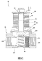
- a gas flow rate control valve 10 in accordance with a first embodiment of the present invention is shown comprised of a lower valve block 20 , an upper valve block 30 , a magnetic column 40 , and a spring member 50 .
- the lower valve block 20 comprises a gas flow passage 22 for the passing of a fuel gas.
- the gas flow passage 22 comprises a gas inlet 221 , a gas outlet 222 , a communication hole 224 between the gas inlet 221 and the gas outlet 222 , and an opening 223 located above the communication hole 224 .
- the inlet 221 is for letting the fuel gas go into the inside of the lower valve block 20 .
- the outlet 221 is for letting the fuel gas to out of the lower valve block 20 .
- the opening 223 is in communication with a middle part of the passage 22 and located at the top side of the lower valve block 20 .
- the lower valve block 20 further comprises a filter gauze 24 mounted in the middle part of the gas flow passage 22 between the gas inlet 221 and the gas outlet 223 to remove solid matters from the fuel gas passing through the lower valve block 20 .
- the upper valve block 30 comprises a tube 32 , a seal 33 , and a solenoid coil assembly 34 surrounding the tube 32 .
- the upper valve block 30 is fixedly fastened to the top side of the lower valve block 20 to block the opening 223 .
- the tube 32 is kept in communication with the opening 223 of the gas flow passage 22 and located above and aligned with the communication hole 224 for accommodating the magnetic column 40 .
- the seal 33 seals the top side of the tube 32 to prevent gas leakage.
- the solenoid coil assembly 34 surrounds the tube 32 . When electrically conducted, the solenoid coil assembly 34 will generate a magnetic field to move the magnetic column 40 .
- the intensity of the magnetic field generated by the solenoid coil assembly 34 will become stronger, i.e., the attractive force produced by the solenoid coil assembly 34 to move the magnetic column 40 will become greater. Further, changing the direction of the current inputted to the solenoid coil assembly 34 causes change of the polarity of the magnetic field, and the direction of the force applied to the magnetic column 40 is reversed.
- the magnetic column 40 comprises a magnetic portion 42 and a stopper 44 .
- the magnetic portion 42 is formed of a permanent magnet.
- the stopper 44 is made of rubber and affixed to the bottom side of the magnetic portion 42 .
- the magnetic portion 42 is inserted into the tube 32 within the working range of the solenoid coil assembly 34 . Therefore, the magnetic portion 42 can be moved up and down in the tube 32 .
- the top side of the magnetic portion 42 is normally kept at the elevation below the center of the solenoid coil assembly 34 for enabling the polarity at the top side of the magnetic column 40 to be driven by the solenoid coil assembly 34 .
- the magnetic column 40 is moved axially along the tube 32 .
- the stopper 44 relatively changes the open ratio of the communication hole 224 of the gas flow passage 22 , thereby regulating the flow rate of the fuel gas passing through the communication hole 224 .
- the stopper 44 blocks the entire gas flow passage 22 , and the fuel gas is prohibited from passing through the lower valve block 20 .
- the spring member 50 is a compression spring that can be mounted on one of the top and bottom sides of the magnetic column 40 . According to this embodiment, the spring member 50 is provided at the bottom side of the magnetic column 40 , so that the gas flow rate control valve 10 is a normal open valve. The spring member 50 extends in the axial direction of the magnetic column 40 to keep the magnetic column 40 in balance and to provide a return force to the magnetic column 40 after each displacement of the magnetic column 40 .
- the solenoid coil assembly 34 does not generate any magnetic field when it is not electrically conducted; the stopper 44 of the magnetic column 40 is lifted by the spring member 50 for allowing the fuel gas to pass through the gas flow passage 22 of the lower valve block 20, and the top side of the magnetic portion 42 is normally kept below the elevation of the center of the solenoid coil assembly 34 .
- the solenoid coil assembly 34 When electric current goes through the solenoid coil assembly 34 , the solenoid coil assembly 34 generates a magnetic field. If the polarity at the bottom side of the solenoid coil assembly 34 is same as the polarity at the top side of the magnetic portion 42 of the magnetic column 40 , the magnetic portion 42 of the magnetic column 40 will be forced downwards by the magnetic repulsive force.
- the ratio of the open cross-sectional area of the communication hole 224 . is relatively reduced, and therefore the flow rate of the fuel gas is relatively reduced.
- the intensity of the magnetic filed generated by the solenoid coil assembly 34 will be relatively adjusted, and the magnetic portion 42 will be moved subject to the intensity of the magnetic field, achieving accurate gas flow rate control.
- the magnetic force generated by the solenoid coil assembly 34 surpasses the spring force of the spring member 50 , the magnetic portion 42 is forced downwards to the close position P1 to block the gas flow passage 22 of the lower valve block 20 , stopping the fuel gas from passing through the lower valve block 20 .
- inputting an electric current to the gas flow rate control valve 10 causes the solenoid coil assembly 34 to generate a magnetic field that controls the amount of displacement of the magnetic column 40 , thereby adjusting the open cross sectional area of the communication hole 224 of the gas flow passage 22 (the greater the X value is the smaller the open cross-sectional area will be), and therefore the desired gas flow rate control is achieved.
- the magnetic portion 42 according to this embodiment is formed of a permanent magnet to have a small magnetic hysteresis. Therefore, there is a certain relationship between the value of the input current and the generated magnetic force, i.e., the rise curve and the decline curve are approximately equal in the input current-magnetic column 40 displacement relationship diagram.
- the gas flow rate control valve 10 of the present invention has an accurate gas flow rate control characteristic. Further, when compared to conventional designs, the invention has simple structure and accurate action characteristics.
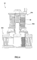
- FIGS. 4 and 5 show a gas flow rate control valve 12 in accordance with a second embodiment of the present invention.
- the gas flow rate control valve 12 is comprised of a lower valve block 20A , an upper valve block 30A , a magnetic column 40A , and a spring member 60 .
- the spring member 60 is a compression spring provided at the top side of the magnetic column 40A .
- the gas flow rate control valve 12 is a normal close valve.
- the spring member 60 extends in the axial direction of the magnetic column 40A to keep the magnetic column 40A in balance and to provide a return force to the magnetic column 40A after each displacement of the magnetic column 40A .
- FIGS. 6 and 7 show a gas flow rate control valve 14 in accordance with a third embodiment of the present invention.
- the gas flow rate control valve 14 is comprised of a lower valve block 20B , an upper valve block 30B , a magnetic column 40B , and a spring member 50B.
- the magnetic portion 42B of the magnetic column 40B is comprised of a permanent magnet 421 and a magnetically conductive block 422
- the stopper 44B of the magnetic column 40B is a rubber member capped on the bottom side of the magnetically conductive block 422 .
- This embodiment shows a different configuration of the magnetic column 40A .
- the magnetically conductive block 422 is made of a ferrous material, having a bottom mounting bolt 423 for securing the rubber stopper 44B .
- the gas flow rate control valve 14 further comprises a supplementary spring member 70 .
- the supplementary spring member 70 and the spring member 50B are respectively provided at the two opposite sides of the magnetic column 40B .
- the spring member 50B is provided at the bottom side of the magnetic column 40B
- the gas flow rate control valve 14 is a normal open valve
- the supplementary spring member 70 is provided at the top side of the magnetic column 40B
- the supplementary spring member 70 and the spring member 50B work in reversed directions, providing a force to move the magnetic column 40B .
- the force of the supplementary spring member 70 is smaller than the force of the spring member 50B.
- the supplementary spring member 70 assists the gas flow rate control valve 14 in regulating the force relative to the magnetic column 50B so that the control of the gas flow rate control valve 14 is close to a linear control, assuring accurate control of the gas flow rate. Therefore, this third embodiment achieves the same effects as the aforesaid first and second embodiments.
- the top side of the magnetic portion 42 is normally disposed below the elevation of the center of the solenoid coil assembly 34 , assuring the magnetic pole at the top side of the magnetic column 40 to be positively driven by the solenoid coil assembly 34 ; on the contrary, the bottom side of the magnetic portion 42 can be normally disposed above the elevation of the center of the solenoid coil assembly 34 , assuring the magnetic pole at the bottom side of the magnetic column 40 to be positively driven by the solenoid coil assembly 34 .
Abstract
A gas flow rate control valve (10, 12, 14) includes a lower valve block (20, 20A, 20B) defining a gas flow passage (22), and an upper valve block (30, 30A, 30B) having a tube (32) disposed in communication with the gas flow passage (22), and a solenoid coil assembly (34) surrounding the tube (32) for generating a magnetic field. A magnetic column (40, 40A, 40B) has a magnetic portion (42, 42B) inserted into the tube (32) and axially movable by the magnetic field generated by the solenoid coil assembly (34), and a stopper (44, 44B) movable with the magnetic portion (42, 42B) to change the open cross-sectional area of the gas flow passage (22) so as to control the flow rate of the fuel gas passing through the gas flow passage (22). A spring member (50, 50B, 60) is provided at one of the top and bottom sides of the magnetic column (40, 40A, 40B) to keep the magnetic column (40, 40A, 40B) in balance and to provide a return force to the magnetic column (40, 40A, 40B) after displacement of the magnetic column (40, 40A, 40B).
Description
- The present invention relates generally to gas equipments and more particularly, to a gas flow rate control valve for controlling the flow rate of a fuel gas accurately.
- Taiwan patent publication number
M322516 - According to the aforesaid prior art design, the gas flow rate control is limited to the design of the gas flow rate control holes, i.e., the gas flow rate control holes allow regulation of the gas flow rate step by step, however they do not allow for linear gas flow rate control. This inconvenient gas flow rate control method cannot satisfy user's different demands. Further, when rotating the rotary gas supply control disk to regulate the gas flow rate, the supply of the fuel gas may be interrupted before alignment of the next gas flow rate control hole with the guide hole, resulting in flame failure. Therefore, this design of gas flow rate control valve is not safe in use.
- Therefore, it is desirable to provide a gas flow rate control valve that eliminates the aforesaid problems.
- The present invention has been accomplished under the circumstances in view. It is the main objective of the present invention to provide a gas flow rate control valve, which directly controls adjustment of the open cross-sectional area of the gas flow passage subject to the amount of displacement of a magnetic column, achieving accurate gas flow rate control.
- It is another objective of the present invention to provide a gas flow rate control valve, which has a simple structure that works positively.
- To achieve these objectives of the present invention, the gas flow rate control valve comprises: a lower valve block, which defines a gas flow passage for the passing of a fuel gas, an upper valve block, which is fixedly mounted on a top side of the lower valve block and includes a tube disposed in communication with the gas flow passage, and a solenoid coil assembly surrounding the tube for generating a magnetic field, a magnetic column, which includes a magnetic portion inserted into the tube and axially movable in the tube by the magnetic field generated by the solenoid coil assembly, and a stopper movable with the magnetic portion to change an open cross-sectional area of the gas flow passage so as to further control a flow rate of the fuel gas passing through the gas flow passage, and a spring member provided at one of top and bottom sides of the magnetic column to keep the magnetic column in balance and to provide a return force to the magnetic column after a displacement of the magnetic column.
- By means of controlling the solenoid coil assembly to generate a magnetic field and to further control the amount of displacement of the magnetic column, the open cross-sectional area of the gas flow passage is relatively adjusted, achieving accurate gas flow rate control. The linear relationship between the magnetic field generated by the solenoid coil assembly and the amount of displacement of the magnetic column assures accurate gas flow rate control. Further, the gas flow rate control valve has simple structure and positive working characteristics.
- Further scope of applicability of the present invention will become apparent from the detailed description given hereinafter. However, it should be understood that the detailed description and specific examples, while indicating preferred embodiments of the invention, are given by way of illustration only, since various changes and modifications within the spirit and scope of the invention will become apparent to those skilled in the art from this detailed description.
- The present invention will become more fully understood from the detailed description given herein below and the accompanying drawings which are given by way of illustration only, and thus are not limitative of the present invention, and wherein:
-
FIG. 1 is an exploded view of a gas flow rate control valve in accordance with a first embodiment of the present invention; -
FIG. 2 is a sectional assembly view of the gas flow rate control valve in accordance with the first embodiment of the present invention; -
FIG. 3 is similar toFIG. 2 but showing the magnetic column moved; -
FIG. 4 is a sectional assembly view of a gas flow rate control valve in accordance with a second embodiment of the present invention; -
FIG. 5 is similar toFIG. 4 but showing the magnetic column moved; -
FIG. 6 is a sectional assembly view of the gas flow rate control valve in accordance with a third embodiment of the present invention, and -
FIG. 7 is similar toFIG. 6 but showing the magnetic column moved. - Referring to
FIG. 1 , a gas flowrate control valve 10 in accordance with a first embodiment of the present invention is shown comprised of alower valve block 20, anupper valve block 30, amagnetic column 40, and aspring member 50. - The
lower valve block 20 comprises agas flow passage 22 for the passing of a fuel gas. Thegas flow passage 22 comprises agas inlet 221, agas outlet 222, acommunication hole 224 between thegas inlet 221 and thegas outlet 222, and anopening 223 located above thecommunication hole 224. Theinlet 221 is for letting the fuel gas go into the inside of thelower valve block 20. Theoutlet 221 is for letting the fuel gas to out of thelower valve block 20. The opening 223 is in communication with a middle part of thepassage 22 and located at the top side of thelower valve block 20. Normally, the fuel gas flows through thegas inlet 221 to the opening 223 and then flows through thecommunication hole 224 and then thegas outlet 222 to the outside of thelower valve block 20. Thelower valve block 20 further comprises afilter gauze 24 mounted in the middle part of thegas flow passage 22 between thegas inlet 221 and thegas outlet 223 to remove solid matters from the fuel gas passing through thelower valve block 20. - The
upper valve block 30 comprises atube 32, aseal 33, and asolenoid coil assembly 34 surrounding thetube 32. Theupper valve block 30 is fixedly fastened to the top side of thelower valve block 20 to block theopening 223. Thetube 32 is kept in communication with the opening 223 of thegas flow passage 22 and located above and aligned with thecommunication hole 224 for accommodating themagnetic column 40. Theseal 33 seals the top side of thetube 32 to prevent gas leakage. Thesolenoid coil assembly 34 surrounds thetube 32. When electrically conducted, thesolenoid coil assembly 34 will generate a magnetic field to move themagnetic column 40. When the electric current to thesolenoid coil assembly 34 is increased, the intensity of the magnetic field generated by thesolenoid coil assembly 34 will become stronger, i.e., the attractive force produced by thesolenoid coil assembly 34 to move themagnetic column 40 will become greater. Further, changing the direction of the current inputted to thesolenoid coil assembly 34 causes change of the polarity of the magnetic field, and the direction of the force applied to themagnetic column 40 is reversed. - The
magnetic column 40 comprises amagnetic portion 42 and astopper 44. Themagnetic portion 42 is formed of a permanent magnet. Thestopper 44 is made of rubber and affixed to the bottom side of themagnetic portion 42. Themagnetic portion 42 is inserted into thetube 32 within the working range of thesolenoid coil assembly 34. Therefore, themagnetic portion 42 can be moved up and down in thetube 32. Because two reversed polarities (S pole and N pole) are produced at two opposite sides relative to the reference line at the center of thesolenoid coil assembly 34 when thesolenoid coil assembly 34 is electrically conducted, the top side of themagnetic portion 42 is normally kept at the elevation below the center of thesolenoid coil assembly 34 for enabling the polarity at the top side of themagnetic column 40 to be driven by thesolenoid coil assembly 34. Subject to the effect of the magnetic field of thesolenoid coil assembly 34 acted upon themagnetic portion 42, themagnetic column 40 is moved axially along thetube 32. During displacement of themagnetic column 40 along thetube 32, thestopper 44 relatively changes the open ratio of thecommunication hole 224 of thegas flow passage 22, thereby regulating the flow rate of the fuel gas passing through thecommunication hole 224. When themagnetic column 40 is moved to a close position P1, thestopper 44 blocks the entiregas flow passage 22, and the fuel gas is prohibited from passing through thelower valve block 20. - The
spring member 50 is a compression spring that can be mounted on one of the top and bottom sides of themagnetic column 40. According to this embodiment, thespring member 50 is provided at the bottom side of themagnetic column 40, so that the gas flowrate control valve 10 is a normal open valve. Thespring member 50 extends in the axial direction of themagnetic column 40 to keep themagnetic column 40 in balance and to provide a return force to themagnetic column 40 after each displacement of themagnetic column 40. - Based on the aforesaid structure, the
solenoid coil assembly 34 does not generate any magnetic field when it is not electrically conducted; thestopper 44 of themagnetic column 40 is lifted by thespring member 50 for allowing the fuel gas to pass through thegas flow passage 22 of thelower valve block 20, and the top side of themagnetic portion 42 is normally kept below the elevation of the center of thesolenoid coil assembly 34. When electric current goes through thesolenoid coil assembly 34, thesolenoid coil assembly 34 generates a magnetic field. If the polarity at the bottom side of thesolenoid coil assembly 34 is same as the polarity at the top side of themagnetic portion 42 of themagnetic column 40, themagnetic portion 42 of themagnetic column 40 will be forced downwards by the magnetic repulsive force. At this time, the ratio of the open cross-sectional area of the communication hole 224.is relatively reduced, and therefore the flow rate of the fuel gas is relatively reduced. When the user regulates the amount of the electric current passing through thesolenoid coil assembly 34 through an operating interface, the intensity of the magnetic filed generated by thesolenoid coil assembly 34 will be relatively adjusted, and themagnetic portion 42 will be moved subject to the intensity of the magnetic field, achieving accurate gas flow rate control. When the magnetic force generated by thesolenoid coil assembly 34 surpasses the spring force of thespring member 50, themagnetic portion 42 is forced downwards to the close position P1 to block thegas flow passage 22 of thelower valve block 20, stopping the fuel gas from passing through thelower valve block 20. - Further, the cooperation between the
spring member 50 and the permanent magnet of themagnetic portion 42 has another effect. For easy understanding of this effect, we hereinafter explain the relation of axial force balance between thespring member 50 and the permanent magnet of themagnetic column 40 as follows:
- Fm: Magnetic force of the
solenoid coil assembly 34 acted upon themagnetic portion 42; - K: Spring constant of the
spring member 50; - X: Amount of displacement of the
magnetic column 40. - Based on the aforesaid structure, inputting an electric current to the gas flow
rate control valve 10 causes thesolenoid coil assembly 34 to generate a magnetic field that controls the amount of displacement of themagnetic column 40, thereby adjusting the open cross sectional area of thecommunication hole 224 of the gas flow passage 22 (the greater the X value is the smaller the open cross-sectional area will be), and therefore the desired gas flow rate control is achieved. Further, themagnetic portion 42 according to this embodiment is formed of a permanent magnet to have a small magnetic hysteresis. Therefore, there is a certain relationship between the value of the input current and the generated magnetic force, i.e., the rise curve and the decline curve are approximately equal in the input current-magnetic column 40 displacement relationship diagram. According to test, when an input current of a certain value causes an increase of a displacement and a reverse input current of the same value causes a decrease of a displacement, the error therebetween is below 3-5%. Therefore, the gas flowrate control valve 10 of the present invention has an accurate gas flow rate control characteristic. Further, when compared to conventional designs, the invention has simple structure and accurate action characteristics. -
FIGS. 4 and5 show a gas flowrate control valve 12 in accordance with a second embodiment of the present invention. Similar to the aforesaid first embodiment, the gas flowrate control valve 12 is comprised of alower valve block 20A, anupper valve block 30A, amagnetic column 40A, and aspring member 60. According to this second embodiment, thespring member 60 is a compression spring provided at the top side of themagnetic column 40A. The gas flowrate control valve 12 is a normal close valve. Thespring member 60 extends in the axial direction of themagnetic column 40A to keep themagnetic column 40A in balance and to provide a return force to themagnetic column 40A after each displacement of themagnetic column 40A. - Based on the aforesaid arrangement, the working direction of the
magnetic column 40A is reversed to that of the aforesaid first embodiment. Therefore, this second embodiment achieves the same effects as the aforesaid first embodiment. -
FIGS. 6 and7 show a gas flowrate control valve 14 in accordance with a third embodiment of the present invention. Similar to the aforesaid first embodiment, the gas flowrate control valve 14 is comprised of alower valve block 20B, anupper valve block 30B, amagnetic column 40B, and aspring member 50B. According to this embodiment, themagnetic portion 42B of themagnetic column 40B is comprised of apermanent magnet 421 and a magneticallyconductive block 422, and thestopper 44B of themagnetic column 40B is a rubber member capped on the bottom side of the magneticallyconductive block 422. This embodiment shows a different configuration of themagnetic column 40A. The magneticallyconductive block 422 is made of a ferrous material, having abottom mounting bolt 423 for securing therubber stopper 44B. However, the design of thebottom mounting bolt 423 is not a limitation. The gas flowrate control valve 14 further comprises asupplementary spring member 70. Thesupplementary spring member 70 and thespring member 50B are respectively provided at the two opposite sides of themagnetic column 40B. According to this embodiment, thespring member 50B is provided at the bottom side of themagnetic column 40B, and the gas flowrate control valve 14 is a normal open valve; thesupplementary spring member 70 is provided at the top side of themagnetic column 40B; thesupplementary spring member 70 and thespring member 50B work in reversed directions, providing a force to move themagnetic column 40B. Further, the force of thesupplementary spring member 70 is smaller than the force of thespring member 50B. - Subject to the aforesaid arrangement, the
supplementary spring member 70 assists the gas flowrate control valve 14 in regulating the force relative to themagnetic column 50B so that the control of the gas flowrate control valve 14 is close to a linear control, assuring accurate control of the gas flow rate. Therefore, this third embodiment achieves the same effects as the aforesaid first and second embodiments. - It is to be understood that the top side of the
magnetic portion 42 according to the first embodiment is normally disposed below the elevation of the center of thesolenoid coil assembly 34, assuring the magnetic pole at the top side of themagnetic column 40 to be positively driven by thesolenoid coil assembly 34; on the contrary, the bottom side of themagnetic portion 42 can be normally disposed above the elevation of the center of thesolenoid coil assembly 34, assuring the magnetic pole at the bottom side of themagnetic column 40 to be positively driven by thesolenoid coil assembly 34.
The invention being thus described, it will be obvious that the same may be varied in many ways. Such variations are not to be regarded as a departure from the spirit and scope of the invention, and all such modifications as would be obvious to one skilled in the art are intended to be included within the scope of the following claims.
Claims (9)
- A gas flow rate control valve (10, 12, 14) comprising:a lower valve block (20, 20A, 20B) having a gas flow passage (22) for the passing of a fuel gas;an upper valve block (30, 30A, 30B) fixedly mounted on a top side of the lower valve block (20, 20A, 20B), the upper valve block (20, 20A, 20B) including a tube (32) disposed in communication with the gas flow passage (22), and a solenoid coil assembly (34) surrounding the tube (32) for generating a magnetic field when the solenoid coil assembly (34) is electrically conducted,characterized in that :a magnetic column (40, 40A, 40B) having a magnetic portion (42, 42B) inserted into the tube (32) and axially movable in the tube (32) by the magnetic field generated by the solenoid coil assembly (34), the magnetic portion (42, 42B) is comprised of a permanent magnet (421), and a stopper (44, 44B) movable with the magnetic portion (42, 42B) to change an open cross-sectional area of the gas flow passage (22) so as to control a flow rate of the fuel gas passing through the gas flow passage (22); anda spring member (50, 50B, 60) provided at one of top and bottom sides of the magnetic column (40, 40A, 40B) and extending in an axial direction of the magnetic column (40, 40A, 40B) to keep the magnetic column (40, 40A, 40B) in balance and to provide a return force to the magnetic column (40, 40A, 40B).
- The gas flow rate control valve (10, 12, 14) as claimed in claim 1, wherein the magnetic portion (42, 42B) further comprises a magnetically conductive block (422).
- The gas flow rate control valve (10, 12, 14) as claimed in claim 1, wherein the magnetic portion (42, 42B) has a top side normally disposed below an elevation of a center of the solenoid coil assembly (34).
- The gas flow rate control valve (10, 12, 14) as claimed in claim 1, wherein the lower valve block (20, 20A, 20B) further comprises a filter gauze (24) mounted in the gas flow passage (22).
- The gas flow rate control valve (10, 12, 14) as claimed in claim 1, wherein the spring member (50, 50B, 60) is a compression spring provided at the bottom side of the magnetic column (40, 40A, 40B), such that the gas flow rate control valve (10, 12, 14) is in a normal open manner.
- The gas flow rate control valve (10, 12, 14) as claimed in claim 1, wherein the spring member (50, 50B, 60) is a compression spring provided at the top side of the magnetic column (40, 40A, 40B), such that the gas flow rate control valve (10, 12, 14) is in a normal close manner.
- The gas flow rate control valve (10, 12, 14) as claimed in claim 1, further comprising a supplementary spring member (70) provided at one of the top and bottom sides of the magnetic column (40, 40A, 40B) opposite to the spring member (50, 50B, 60); the supplementary spring member (70) and the spring member (50, 50B, 60) work in reversed directions against each other.
- The gas flow rate control valve (10, 12, 14) as claimed in claim 7, wherein the supplementary spring member (70) has a spring force smaller than that of the spring member (50, 50B, 60).
- The gas flow rate control valve (10, 12, 14) as claimed in claim 1, wherein the magnetic portion (42, 42B) has a bottom side normally disposed above an elevation of a center of the solenoid coil assembly (34).
Applications Claiming Priority (1)
| Application Number | Priority Date | Filing Date | Title |
|---|---|---|---|
| TW097105957A TW200936960A (en) | 2008-02-20 | 2008-02-20 | LPG flow rate control valve |
Publications (1)
| Publication Number | Publication Date |
|---|---|
| EP2093486A2 true EP2093486A2 (en) | 2009-08-26 |
Family
ID=40506305
Family Applications (1)
| Application Number | Title | Priority Date | Filing Date |
|---|---|---|---|
| EP08014995A Withdrawn EP2093486A2 (en) | 2008-02-20 | 2008-08-25 | Gas flow rate control valve |
Country Status (3)
| Country | Link |
|---|---|
| US (1) | US20090206291A1 (en) |
| EP (1) | EP2093486A2 (en) |
| TW (1) | TW200936960A (en) |
Families Citing this family (12)
| Publication number | Priority date | Publication date | Assignee | Title |
|---|---|---|---|---|
| JP5891733B2 (en) * | 2011-11-18 | 2016-03-23 | アイシン精機株式会社 | solenoid valve |
| US20130298848A1 (en) * | 2012-05-14 | 2013-11-14 | Girard Systems | Gas flow modulator and method for regulating gas flow |
| CN103836785B (en) * | 2012-11-26 | 2016-09-28 | 关隆股份有限公司 | Direct press type water heater and control method thereof |
| TWI490439B (en) * | 2012-12-03 | 2015-07-01 | Grand Mate Co Ltd | A gas control valve and a gas burner using the gas control valve |
| US9898927B2 (en) | 2013-09-11 | 2018-02-20 | Grand Mate Co., Ltd. | Wi-Fi/radio frequency converting device |
| US20170211717A1 (en) * | 2014-04-04 | 2017-07-27 | Mecanique Analytique Inc. | Magnetic metering valve and method of operating the same |
| ITUB20152426A1 (en) * | 2015-07-23 | 2017-01-23 | Tre P Eng S R L | ELECTRO-PILOSTATIC VALVE FOR GAS BURNERS |
| TWI669464B (en) | 2018-01-25 | 2019-08-21 | 關隆股份有限公司 | Gas appliance, gas valve and control method thereof |
| CN108913251B (en) * | 2018-08-20 | 2023-09-19 | 长江大学 | Bubble cap special for natural gas dehydration |
| TWI707108B (en) * | 2019-06-11 | 2020-10-11 | 關隆股份有限公司 | Flow control valve for gas stove |
| CN112112994B (en) * | 2019-06-20 | 2022-08-12 | 关隆股份有限公司 | Flow regulating valve for gas stove |
| US10871235B1 (en) | 2019-08-07 | 2020-12-22 | Grand Mate Co., Ltd. | Flow regulating valve of gas stove |
Citations (1)
| Publication number | Priority date | Publication date | Assignee | Title |
|---|---|---|---|---|
| TW322516B (en) | 1995-11-15 | 1997-12-11 | Rohco Inc Mcgean |
-
2008
- 2008-02-20 TW TW097105957A patent/TW200936960A/en unknown
- 2008-08-25 EP EP08014995A patent/EP2093486A2/en not_active Withdrawn
- 2008-09-04 US US12/204,112 patent/US20090206291A1/en not_active Abandoned
Patent Citations (1)
| Publication number | Priority date | Publication date | Assignee | Title |
|---|---|---|---|---|
| TW322516B (en) | 1995-11-15 | 1997-12-11 | Rohco Inc Mcgean |
Also Published As
| Publication number | Publication date |
|---|---|
| US20090206291A1 (en) | 2009-08-20 |
| TW200936960A (en) | 2009-09-01 |
| TWI355475B (en) | 2012-01-01 |
Similar Documents
| Publication | Publication Date | Title |
|---|---|---|
| EP2093486A2 (en) | Gas flow rate control valve | |
| EP2103835B1 (en) | Damping valve | |
| JP5427296B2 (en) | Gas pressure regulator | |
| CN101512201B (en) | Direct-acting pilot pressure control solenoid | |
| US4947893A (en) | Variable force solenoid pressure regulator for electronic transmission controller | |
| EP0393248A2 (en) | Transmission pressure regulator | |
| EP2166423A1 (en) | Balanced fluid valve | |
| DE102007011127A1 (en) | Pilot operated valve with pressure balanced poppet valve member | |
| WO2005124207A1 (en) | Variable flow valve | |
| JP5406993B2 (en) | Gas pressure regulator | |
| GB2131621A (en) | Proportional solenoid actuated valve | |
| US4791958A (en) | Solenoid controlled fluid valve | |
| CN110998155A (en) | Proportional valve for controlling a gaseous medium | |
| US9366354B2 (en) | Normally closed solenoid valve | |
| JP2012237446A (en) | Pressure reducer | |
| KR101105523B1 (en) | Proportional pressure control valve | |
| EP2868970B1 (en) | Regulating device | |
| JP2007051780A (en) | Relief valve | |
| US8220774B2 (en) | Proportional pilot acting valve | |
| KR20040104941A (en) | Electro-pneumatic air pressure regulator | |
| JP5809967B2 (en) | Pressure regulator for fuel cell system | |
| KR100736772B1 (en) | Proportional control valve with pzt actuator | |
| EP3082009B1 (en) | Pressure regulator | |
| DE3608060A1 (en) | GAS VALVE | |
| CN210830684U (en) | Safety valve for controlling gas flow in a modulated manner |
Legal Events
| Date | Code | Title | Description |
|---|---|---|---|
| PUAI | Public reference made under article 153(3) epc to a published international application that has entered the european phase |
Free format text: ORIGINAL CODE: 0009012 |
|
| 17P | Request for examination filed |
Effective date: 20080825 |
|
| AK | Designated contracting states |
Kind code of ref document: A2 Designated state(s): AT BE BG CH CY CZ DE DK EE ES FI FR GB GR HR HU IE IS IT LI LT LU LV MC MT NL NO PL PT RO SE SI SK TR |
|
| AX | Request for extension of the european patent |
Extension state: AL BA MK RS |
|
| STAA | Information on the status of an ep patent application or granted ep patent |
Free format text: STATUS: THE APPLICATION IS DEEMED TO BE WITHDRAWN |
|
| 18D | Application deemed to be withdrawn |
Effective date: 20120301 |