EP2093475B1 - Compressor fill method and apparatus - Google Patents
Compressor fill method and apparatus Download PDFInfo
- Publication number
- EP2093475B1 EP2093475B1 EP09153260.6A EP09153260A EP2093475B1 EP 2093475 B1 EP2093475 B1 EP 2093475B1 EP 09153260 A EP09153260 A EP 09153260A EP 2093475 B1 EP2093475 B1 EP 2093475B1
- Authority
- EP
- European Patent Office
- Prior art keywords
- gas
- vessel
- rate
- temperature
- pressure
- Prior art date
- Legal status (The legal status is an assumption and is not a legal conclusion. Google has not performed a legal analysis and makes no representation as to the accuracy of the status listed.)
- Active
Links
- 238000000034 method Methods 0.000 title claims description 19
- 230000003247 decreasing effect Effects 0.000 claims description 2
- 239000007789 gas Substances 0.000 description 84
- 239000007788 liquid Substances 0.000 description 13
- UFHFLCQGNIYNRP-UHFFFAOYSA-N Hydrogen Chemical compound [H][H] UFHFLCQGNIYNRP-UHFFFAOYSA-N 0.000 description 10
- 239000012530 fluid Substances 0.000 description 10
- 239000001257 hydrogen Substances 0.000 description 9
- 229910052739 hydrogen Inorganic materials 0.000 description 9
- 239000000446 fuel Substances 0.000 description 8
- 239000002828 fuel tank Substances 0.000 description 7
- 230000008878 coupling Effects 0.000 description 6
- 238000010168 coupling process Methods 0.000 description 6
- 238000005859 coupling reaction Methods 0.000 description 6
- 238000004891 communication Methods 0.000 description 5
- 238000013021 overheating Methods 0.000 description 5
- 238000005259 measurement Methods 0.000 description 4
- VNWKTOKETHGBQD-UHFFFAOYSA-N methane Chemical compound C VNWKTOKETHGBQD-UHFFFAOYSA-N 0.000 description 4
- 238000009529 body temperature measurement Methods 0.000 description 3
- 238000001816 cooling Methods 0.000 description 2
- 239000004215 Carbon black (E152) Substances 0.000 description 1
- 238000009530 blood pressure measurement Methods 0.000 description 1
- 239000006227 byproduct Substances 0.000 description 1
- 238000002485 combustion reaction Methods 0.000 description 1
- 238000010586 diagram Methods 0.000 description 1
- 238000005868 electrolysis reaction Methods 0.000 description 1
- 230000007613 environmental effect Effects 0.000 description 1
- 239000003502 gasoline Substances 0.000 description 1
- 239000005431 greenhouse gas Substances 0.000 description 1
- 229930195733 hydrocarbon Natural products 0.000 description 1
- 150000002430 hydrocarbons Chemical class 0.000 description 1
- 150000002431 hydrogen Chemical class 0.000 description 1
- 239000003345 natural gas Substances 0.000 description 1
- 230000008054 signal transmission Effects 0.000 description 1
- 239000006200 vaporizer Substances 0.000 description 1
Images

Classifications
-
- F—MECHANICAL ENGINEERING; LIGHTING; HEATING; WEAPONS; BLASTING
- F17—STORING OR DISTRIBUTING GASES OR LIQUIDS
- F17C—VESSELS FOR CONTAINING OR STORING COMPRESSED, LIQUEFIED OR SOLIDIFIED GASES; FIXED-CAPACITY GAS-HOLDERS; FILLING VESSELS WITH, OR DISCHARGING FROM VESSELS, COMPRESSED, LIQUEFIED, OR SOLIDIFIED GASES
- F17C5/00—Methods or apparatus for filling containers with liquefied, solidified, or compressed gases under pressures
- F17C5/06—Methods or apparatus for filling containers with liquefied, solidified, or compressed gases under pressures for filling with compressed gases
-
- F—MECHANICAL ENGINEERING; LIGHTING; HEATING; WEAPONS; BLASTING
- F17—STORING OR DISTRIBUTING GASES OR LIQUIDS
- F17C—VESSELS FOR CONTAINING OR STORING COMPRESSED, LIQUEFIED OR SOLIDIFIED GASES; FIXED-CAPACITY GAS-HOLDERS; FILLING VESSELS WITH, OR DISCHARGING FROM VESSELS, COMPRESSED, LIQUEFIED, OR SOLIDIFIED GASES
- F17C13/00—Details of vessels or of the filling or discharging of vessels
- F17C13/02—Special adaptations of indicating, measuring, or monitoring equipment
- F17C13/025—Special adaptations of indicating, measuring, or monitoring equipment having the pressure as the parameter
-
- F—MECHANICAL ENGINEERING; LIGHTING; HEATING; WEAPONS; BLASTING
- F17—STORING OR DISTRIBUTING GASES OR LIQUIDS
- F17C—VESSELS FOR CONTAINING OR STORING COMPRESSED, LIQUEFIED OR SOLIDIFIED GASES; FIXED-CAPACITY GAS-HOLDERS; FILLING VESSELS WITH, OR DISCHARGING FROM VESSELS, COMPRESSED, LIQUEFIED, OR SOLIDIFIED GASES
- F17C13/00—Details of vessels or of the filling or discharging of vessels
- F17C13/02—Special adaptations of indicating, measuring, or monitoring equipment
- F17C13/026—Special adaptations of indicating, measuring, or monitoring equipment having the temperature as the parameter
-
- F—MECHANICAL ENGINEERING; LIGHTING; HEATING; WEAPONS; BLASTING
- F17—STORING OR DISTRIBUTING GASES OR LIQUIDS
- F17C—VESSELS FOR CONTAINING OR STORING COMPRESSED, LIQUEFIED OR SOLIDIFIED GASES; FIXED-CAPACITY GAS-HOLDERS; FILLING VESSELS WITH, OR DISCHARGING FROM VESSELS, COMPRESSED, LIQUEFIED, OR SOLIDIFIED GASES
- F17C5/00—Methods or apparatus for filling containers with liquefied, solidified, or compressed gases under pressures
- F17C5/002—Automated filling apparatus
- F17C5/007—Automated filling apparatus for individual gas tanks or containers, e.g. in vehicles
-
- F—MECHANICAL ENGINEERING; LIGHTING; HEATING; WEAPONS; BLASTING
- F17—STORING OR DISTRIBUTING GASES OR LIQUIDS
- F17C—VESSELS FOR CONTAINING OR STORING COMPRESSED, LIQUEFIED OR SOLIDIFIED GASES; FIXED-CAPACITY GAS-HOLDERS; FILLING VESSELS WITH, OR DISCHARGING FROM VESSELS, COMPRESSED, LIQUEFIED, OR SOLIDIFIED GASES
- F17C5/00—Methods or apparatus for filling containers with liquefied, solidified, or compressed gases under pressures
- F17C5/02—Methods or apparatus for filling containers with liquefied, solidified, or compressed gases under pressures for filling with liquefied gases
-
- F—MECHANICAL ENGINEERING; LIGHTING; HEATING; WEAPONS; BLASTING
- F17—STORING OR DISTRIBUTING GASES OR LIQUIDS
- F17C—VESSELS FOR CONTAINING OR STORING COMPRESSED, LIQUEFIED OR SOLIDIFIED GASES; FIXED-CAPACITY GAS-HOLDERS; FILLING VESSELS WITH, OR DISCHARGING FROM VESSELS, COMPRESSED, LIQUEFIED, OR SOLIDIFIED GASES
- F17C6/00—Methods and apparatus for filling vessels not under pressure with liquefied or solidified gases
-
- F—MECHANICAL ENGINEERING; LIGHTING; HEATING; WEAPONS; BLASTING
- F17—STORING OR DISTRIBUTING GASES OR LIQUIDS
- F17C—VESSELS FOR CONTAINING OR STORING COMPRESSED, LIQUEFIED OR SOLIDIFIED GASES; FIXED-CAPACITY GAS-HOLDERS; FILLING VESSELS WITH, OR DISCHARGING FROM VESSELS, COMPRESSED, LIQUEFIED, OR SOLIDIFIED GASES
- F17C7/00—Methods or apparatus for discharging liquefied, solidified, or compressed gases from pressure vessels, not covered by another subclass
-
- F—MECHANICAL ENGINEERING; LIGHTING; HEATING; WEAPONS; BLASTING
- F17—STORING OR DISTRIBUTING GASES OR LIQUIDS
- F17C—VESSELS FOR CONTAINING OR STORING COMPRESSED, LIQUEFIED OR SOLIDIFIED GASES; FIXED-CAPACITY GAS-HOLDERS; FILLING VESSELS WITH, OR DISCHARGING FROM VESSELS, COMPRESSED, LIQUEFIED, OR SOLIDIFIED GASES
- F17C9/00—Methods or apparatus for discharging liquefied or solidified gases from vessels not under pressure
-
- F—MECHANICAL ENGINEERING; LIGHTING; HEATING; WEAPONS; BLASTING
- F17—STORING OR DISTRIBUTING GASES OR LIQUIDS
- F17C—VESSELS FOR CONTAINING OR STORING COMPRESSED, LIQUEFIED OR SOLIDIFIED GASES; FIXED-CAPACITY GAS-HOLDERS; FILLING VESSELS WITH, OR DISCHARGING FROM VESSELS, COMPRESSED, LIQUEFIED, OR SOLIDIFIED GASES
- F17C2205/00—Vessel construction, in particular mounting arrangements, attachments or identifications means
- F17C2205/03—Fluid connections, filters, valves, closure means or other attachments
- F17C2205/0302—Fittings, valves, filters, or components in connection with the gas storage device
- F17C2205/0323—Valves
- F17C2205/0326—Valves electrically actuated
-
- F—MECHANICAL ENGINEERING; LIGHTING; HEATING; WEAPONS; BLASTING
- F17—STORING OR DISTRIBUTING GASES OR LIQUIDS
- F17C—VESSELS FOR CONTAINING OR STORING COMPRESSED, LIQUEFIED OR SOLIDIFIED GASES; FIXED-CAPACITY GAS-HOLDERS; FILLING VESSELS WITH, OR DISCHARGING FROM VESSELS, COMPRESSED, LIQUEFIED, OR SOLIDIFIED GASES
- F17C2221/00—Handled fluid, in particular type of fluid
- F17C2221/01—Pure fluids
- F17C2221/012—Hydrogen
-
- F—MECHANICAL ENGINEERING; LIGHTING; HEATING; WEAPONS; BLASTING
- F17—STORING OR DISTRIBUTING GASES OR LIQUIDS
- F17C—VESSELS FOR CONTAINING OR STORING COMPRESSED, LIQUEFIED OR SOLIDIFIED GASES; FIXED-CAPACITY GAS-HOLDERS; FILLING VESSELS WITH, OR DISCHARGING FROM VESSELS, COMPRESSED, LIQUEFIED, OR SOLIDIFIED GASES
- F17C2223/00—Handled fluid before transfer, i.e. state of fluid when stored in the vessel or before transfer from the vessel
- F17C2223/01—Handled fluid before transfer, i.e. state of fluid when stored in the vessel or before transfer from the vessel characterised by the phase
- F17C2223/0107—Single phase
- F17C2223/0123—Single phase gaseous, e.g. CNG, GNC
-
- F—MECHANICAL ENGINEERING; LIGHTING; HEATING; WEAPONS; BLASTING
- F17—STORING OR DISTRIBUTING GASES OR LIQUIDS
- F17C—VESSELS FOR CONTAINING OR STORING COMPRESSED, LIQUEFIED OR SOLIDIFIED GASES; FIXED-CAPACITY GAS-HOLDERS; FILLING VESSELS WITH, OR DISCHARGING FROM VESSELS, COMPRESSED, LIQUEFIED, OR SOLIDIFIED GASES
- F17C2223/00—Handled fluid before transfer, i.e. state of fluid when stored in the vessel or before transfer from the vessel
- F17C2223/01—Handled fluid before transfer, i.e. state of fluid when stored in the vessel or before transfer from the vessel characterised by the phase
- F17C2223/0146—Two-phase
- F17C2223/0153—Liquefied gas, e.g. LPG, GPL
- F17C2223/0161—Liquefied gas, e.g. LPG, GPL cryogenic, e.g. LNG, GNL, PLNG
-
- F—MECHANICAL ENGINEERING; LIGHTING; HEATING; WEAPONS; BLASTING
- F17—STORING OR DISTRIBUTING GASES OR LIQUIDS
- F17C—VESSELS FOR CONTAINING OR STORING COMPRESSED, LIQUEFIED OR SOLIDIFIED GASES; FIXED-CAPACITY GAS-HOLDERS; FILLING VESSELS WITH, OR DISCHARGING FROM VESSELS, COMPRESSED, LIQUEFIED, OR SOLIDIFIED GASES
- F17C2223/00—Handled fluid before transfer, i.e. state of fluid when stored in the vessel or before transfer from the vessel
- F17C2223/03—Handled fluid before transfer, i.e. state of fluid when stored in the vessel or before transfer from the vessel characterised by the pressure level
- F17C2223/033—Small pressure, e.g. for liquefied gas
-
- F—MECHANICAL ENGINEERING; LIGHTING; HEATING; WEAPONS; BLASTING
- F17—STORING OR DISTRIBUTING GASES OR LIQUIDS
- F17C—VESSELS FOR CONTAINING OR STORING COMPRESSED, LIQUEFIED OR SOLIDIFIED GASES; FIXED-CAPACITY GAS-HOLDERS; FILLING VESSELS WITH, OR DISCHARGING FROM VESSELS, COMPRESSED, LIQUEFIED, OR SOLIDIFIED GASES
- F17C2223/00—Handled fluid before transfer, i.e. state of fluid when stored in the vessel or before transfer from the vessel
- F17C2223/03—Handled fluid before transfer, i.e. state of fluid when stored in the vessel or before transfer from the vessel characterised by the pressure level
- F17C2223/035—High pressure (>10 bar)
-
- F—MECHANICAL ENGINEERING; LIGHTING; HEATING; WEAPONS; BLASTING
- F17—STORING OR DISTRIBUTING GASES OR LIQUIDS
- F17C—VESSELS FOR CONTAINING OR STORING COMPRESSED, LIQUEFIED OR SOLIDIFIED GASES; FIXED-CAPACITY GAS-HOLDERS; FILLING VESSELS WITH, OR DISCHARGING FROM VESSELS, COMPRESSED, LIQUEFIED, OR SOLIDIFIED GASES
- F17C2223/00—Handled fluid before transfer, i.e. state of fluid when stored in the vessel or before transfer from the vessel
- F17C2223/04—Handled fluid before transfer, i.e. state of fluid when stored in the vessel or before transfer from the vessel characterised by other properties of handled fluid before transfer
- F17C2223/042—Localisation of the removal point
- F17C2223/046—Localisation of the removal point in the liquid
-
- F—MECHANICAL ENGINEERING; LIGHTING; HEATING; WEAPONS; BLASTING
- F17—STORING OR DISTRIBUTING GASES OR LIQUIDS
- F17C—VESSELS FOR CONTAINING OR STORING COMPRESSED, LIQUEFIED OR SOLIDIFIED GASES; FIXED-CAPACITY GAS-HOLDERS; FILLING VESSELS WITH, OR DISCHARGING FROM VESSELS, COMPRESSED, LIQUEFIED, OR SOLIDIFIED GASES
- F17C2225/00—Handled fluid after transfer, i.e. state of fluid after transfer from the vessel
- F17C2225/01—Handled fluid after transfer, i.e. state of fluid after transfer from the vessel characterised by the phase
- F17C2225/0107—Single phase
- F17C2225/0123—Single phase gaseous, e.g. CNG, GNC
-
- F—MECHANICAL ENGINEERING; LIGHTING; HEATING; WEAPONS; BLASTING
- F17—STORING OR DISTRIBUTING GASES OR LIQUIDS
- F17C—VESSELS FOR CONTAINING OR STORING COMPRESSED, LIQUEFIED OR SOLIDIFIED GASES; FIXED-CAPACITY GAS-HOLDERS; FILLING VESSELS WITH, OR DISCHARGING FROM VESSELS, COMPRESSED, LIQUEFIED, OR SOLIDIFIED GASES
- F17C2225/00—Handled fluid after transfer, i.e. state of fluid after transfer from the vessel
- F17C2225/03—Handled fluid after transfer, i.e. state of fluid after transfer from the vessel characterised by the pressure level
- F17C2225/035—High pressure, i.e. between 10 and 80 bars
-
- F—MECHANICAL ENGINEERING; LIGHTING; HEATING; WEAPONS; BLASTING
- F17—STORING OR DISTRIBUTING GASES OR LIQUIDS
- F17C—VESSELS FOR CONTAINING OR STORING COMPRESSED, LIQUEFIED OR SOLIDIFIED GASES; FIXED-CAPACITY GAS-HOLDERS; FILLING VESSELS WITH, OR DISCHARGING FROM VESSELS, COMPRESSED, LIQUEFIED, OR SOLIDIFIED GASES
- F17C2225/00—Handled fluid after transfer, i.e. state of fluid after transfer from the vessel
- F17C2225/03—Handled fluid after transfer, i.e. state of fluid after transfer from the vessel characterised by the pressure level
- F17C2225/036—Very high pressure, i.e. above 80 bars
-
- F—MECHANICAL ENGINEERING; LIGHTING; HEATING; WEAPONS; BLASTING
- F17—STORING OR DISTRIBUTING GASES OR LIQUIDS
- F17C—VESSELS FOR CONTAINING OR STORING COMPRESSED, LIQUEFIED OR SOLIDIFIED GASES; FIXED-CAPACITY GAS-HOLDERS; FILLING VESSELS WITH, OR DISCHARGING FROM VESSELS, COMPRESSED, LIQUEFIED, OR SOLIDIFIED GASES
- F17C2227/00—Transfer of fluids, i.e. method or means for transferring the fluid; Heat exchange with the fluid
- F17C2227/01—Propulsion of the fluid
- F17C2227/0128—Propulsion of the fluid with pumps or compressors
- F17C2227/0135—Pumps
- F17C2227/0142—Pumps with specified pump type, e.g. piston or impulsive type
-
- F—MECHANICAL ENGINEERING; LIGHTING; HEATING; WEAPONS; BLASTING
- F17—STORING OR DISTRIBUTING GASES OR LIQUIDS
- F17C—VESSELS FOR CONTAINING OR STORING COMPRESSED, LIQUEFIED OR SOLIDIFIED GASES; FIXED-CAPACITY GAS-HOLDERS; FILLING VESSELS WITH, OR DISCHARGING FROM VESSELS, COMPRESSED, LIQUEFIED, OR SOLIDIFIED GASES
- F17C2227/00—Transfer of fluids, i.e. method or means for transferring the fluid; Heat exchange with the fluid
- F17C2227/01—Propulsion of the fluid
- F17C2227/0128—Propulsion of the fluid with pumps or compressors
- F17C2227/0157—Compressors
- F17C2227/0164—Compressors with specified compressor type, e.g. piston or impulsive type
-
- F—MECHANICAL ENGINEERING; LIGHTING; HEATING; WEAPONS; BLASTING
- F17—STORING OR DISTRIBUTING GASES OR LIQUIDS
- F17C—VESSELS FOR CONTAINING OR STORING COMPRESSED, LIQUEFIED OR SOLIDIFIED GASES; FIXED-CAPACITY GAS-HOLDERS; FILLING VESSELS WITH, OR DISCHARGING FROM VESSELS, COMPRESSED, LIQUEFIED, OR SOLIDIFIED GASES
- F17C2227/00—Transfer of fluids, i.e. method or means for transferring the fluid; Heat exchange with the fluid
- F17C2227/03—Heat exchange with the fluid
- F17C2227/0367—Localisation of heat exchange
- F17C2227/0388—Localisation of heat exchange separate
- F17C2227/0393—Localisation of heat exchange separate using a vaporiser
-
- F—MECHANICAL ENGINEERING; LIGHTING; HEATING; WEAPONS; BLASTING
- F17—STORING OR DISTRIBUTING GASES OR LIQUIDS
- F17C—VESSELS FOR CONTAINING OR STORING COMPRESSED, LIQUEFIED OR SOLIDIFIED GASES; FIXED-CAPACITY GAS-HOLDERS; FILLING VESSELS WITH, OR DISCHARGING FROM VESSELS, COMPRESSED, LIQUEFIED, OR SOLIDIFIED GASES
- F17C2250/00—Accessories; Control means; Indicating, measuring or monitoring of parameters
- F17C2250/03—Control means
- F17C2250/032—Control means using computers
-
- F—MECHANICAL ENGINEERING; LIGHTING; HEATING; WEAPONS; BLASTING
- F17—STORING OR DISTRIBUTING GASES OR LIQUIDS
- F17C—VESSELS FOR CONTAINING OR STORING COMPRESSED, LIQUEFIED OR SOLIDIFIED GASES; FIXED-CAPACITY GAS-HOLDERS; FILLING VESSELS WITH, OR DISCHARGING FROM VESSELS, COMPRESSED, LIQUEFIED, OR SOLIDIFIED GASES
- F17C2250/00—Accessories; Control means; Indicating, measuring or monitoring of parameters
- F17C2250/04—Indicating or measuring of parameters as input values
- F17C2250/0404—Parameters indicated or measured
- F17C2250/043—Pressure
-
- F—MECHANICAL ENGINEERING; LIGHTING; HEATING; WEAPONS; BLASTING
- F17—STORING OR DISTRIBUTING GASES OR LIQUIDS
- F17C—VESSELS FOR CONTAINING OR STORING COMPRESSED, LIQUEFIED OR SOLIDIFIED GASES; FIXED-CAPACITY GAS-HOLDERS; FILLING VESSELS WITH, OR DISCHARGING FROM VESSELS, COMPRESSED, LIQUEFIED, OR SOLIDIFIED GASES
- F17C2250/00—Accessories; Control means; Indicating, measuring or monitoring of parameters
- F17C2250/04—Indicating or measuring of parameters as input values
- F17C2250/0404—Parameters indicated or measured
- F17C2250/0439—Temperature
-
- F—MECHANICAL ENGINEERING; LIGHTING; HEATING; WEAPONS; BLASTING
- F17—STORING OR DISTRIBUTING GASES OR LIQUIDS
- F17C—VESSELS FOR CONTAINING OR STORING COMPRESSED, LIQUEFIED OR SOLIDIFIED GASES; FIXED-CAPACITY GAS-HOLDERS; FILLING VESSELS WITH, OR DISCHARGING FROM VESSELS, COMPRESSED, LIQUEFIED, OR SOLIDIFIED GASES
- F17C2250/00—Accessories; Control means; Indicating, measuring or monitoring of parameters
- F17C2250/04—Indicating or measuring of parameters as input values
- F17C2250/0486—Indicating or measuring characterised by the location
- F17C2250/0491—Parameters measured at or inside the vessel
-
- F—MECHANICAL ENGINEERING; LIGHTING; HEATING; WEAPONS; BLASTING
- F17—STORING OR DISTRIBUTING GASES OR LIQUIDS
- F17C—VESSELS FOR CONTAINING OR STORING COMPRESSED, LIQUEFIED OR SOLIDIFIED GASES; FIXED-CAPACITY GAS-HOLDERS; FILLING VESSELS WITH, OR DISCHARGING FROM VESSELS, COMPRESSED, LIQUEFIED, OR SOLIDIFIED GASES
- F17C2250/00—Accessories; Control means; Indicating, measuring or monitoring of parameters
- F17C2250/06—Controlling or regulating of parameters as output values
- F17C2250/0605—Parameters
- F17C2250/0636—Flow or movement of content
-
- F—MECHANICAL ENGINEERING; LIGHTING; HEATING; WEAPONS; BLASTING
- F17—STORING OR DISTRIBUTING GASES OR LIQUIDS
- F17C—VESSELS FOR CONTAINING OR STORING COMPRESSED, LIQUEFIED OR SOLIDIFIED GASES; FIXED-CAPACITY GAS-HOLDERS; FILLING VESSELS WITH, OR DISCHARGING FROM VESSELS, COMPRESSED, LIQUEFIED, OR SOLIDIFIED GASES
- F17C2260/00—Purposes of gas storage and gas handling
- F17C2260/02—Improving properties related to fluid or fluid transfer
- F17C2260/023—Avoiding overheating
-
- F—MECHANICAL ENGINEERING; LIGHTING; HEATING; WEAPONS; BLASTING
- F17—STORING OR DISTRIBUTING GASES OR LIQUIDS
- F17C—VESSELS FOR CONTAINING OR STORING COMPRESSED, LIQUEFIED OR SOLIDIFIED GASES; FIXED-CAPACITY GAS-HOLDERS; FILLING VESSELS WITH, OR DISCHARGING FROM VESSELS, COMPRESSED, LIQUEFIED, OR SOLIDIFIED GASES
- F17C2265/00—Effects achieved by gas storage or gas handling
- F17C2265/06—Fluid distribution
- F17C2265/065—Fluid distribution for refueling vehicle fuel tanks
-
- F—MECHANICAL ENGINEERING; LIGHTING; HEATING; WEAPONS; BLASTING
- F17—STORING OR DISTRIBUTING GASES OR LIQUIDS
- F17C—VESSELS FOR CONTAINING OR STORING COMPRESSED, LIQUEFIED OR SOLIDIFIED GASES; FIXED-CAPACITY GAS-HOLDERS; FILLING VESSELS WITH, OR DISCHARGING FROM VESSELS, COMPRESSED, LIQUEFIED, OR SOLIDIFIED GASES
- F17C2270/00—Applications
- F17C2270/01—Applications for fluid transport or storage
- F17C2270/0134—Applications for fluid transport or storage placed above the ground
- F17C2270/0139—Fuel stations
-
- F—MECHANICAL ENGINEERING; LIGHTING; HEATING; WEAPONS; BLASTING
- F17—STORING OR DISTRIBUTING GASES OR LIQUIDS
- F17C—VESSELS FOR CONTAINING OR STORING COMPRESSED, LIQUEFIED OR SOLIDIFIED GASES; FIXED-CAPACITY GAS-HOLDERS; FILLING VESSELS WITH, OR DISCHARGING FROM VESSELS, COMPRESSED, LIQUEFIED, OR SOLIDIFIED GASES
- F17C2270/00—Applications
- F17C2270/01—Applications for fluid transport or storage
- F17C2270/0165—Applications for fluid transport or storage on the road
- F17C2270/0168—Applications for fluid transport or storage on the road by vehicles
- F17C2270/0171—Trucks
-
- F—MECHANICAL ENGINEERING; LIGHTING; HEATING; WEAPONS; BLASTING
- F17—STORING OR DISTRIBUTING GASES OR LIQUIDS
- F17C—VESSELS FOR CONTAINING OR STORING COMPRESSED, LIQUEFIED OR SOLIDIFIED GASES; FIXED-CAPACITY GAS-HOLDERS; FILLING VESSELS WITH, OR DISCHARGING FROM VESSELS, COMPRESSED, LIQUEFIED, OR SOLIDIFIED GASES
- F17C2270/00—Applications
- F17C2270/01—Applications for fluid transport or storage
- F17C2270/0165—Applications for fluid transport or storage on the road
- F17C2270/0168—Applications for fluid transport or storage on the road by vehicles
- F17C2270/0176—Buses
-
- F—MECHANICAL ENGINEERING; LIGHTING; HEATING; WEAPONS; BLASTING
- F17—STORING OR DISTRIBUTING GASES OR LIQUIDS
- F17C—VESSELS FOR CONTAINING OR STORING COMPRESSED, LIQUEFIED OR SOLIDIFIED GASES; FIXED-CAPACITY GAS-HOLDERS; FILLING VESSELS WITH, OR DISCHARGING FROM VESSELS, COMPRESSED, LIQUEFIED, OR SOLIDIFIED GASES
- F17C2270/00—Applications
- F17C2270/01—Applications for fluid transport or storage
- F17C2270/0165—Applications for fluid transport or storage on the road
- F17C2270/0168—Applications for fluid transport or storage on the road by vehicles
- F17C2270/0178—Cars
-
- Y—GENERAL TAGGING OF NEW TECHNOLOGICAL DEVELOPMENTS; GENERAL TAGGING OF CROSS-SECTIONAL TECHNOLOGIES SPANNING OVER SEVERAL SECTIONS OF THE IPC; TECHNICAL SUBJECTS COVERED BY FORMER USPC CROSS-REFERENCE ART COLLECTIONS [XRACs] AND DIGESTS
- Y02—TECHNOLOGIES OR APPLICATIONS FOR MITIGATION OR ADAPTATION AGAINST CLIMATE CHANGE
- Y02E—REDUCTION OF GREENHOUSE GAS [GHG] EMISSIONS, RELATED TO ENERGY GENERATION, TRANSMISSION OR DISTRIBUTION
- Y02E60/00—Enabling technologies; Technologies with a potential or indirect contribution to GHG emissions mitigation
- Y02E60/30—Hydrogen technology
- Y02E60/32—Hydrogen storage
Description
- This invention relates to an apparatus and a method for filling a vessel, such as a fuel tank, with a compressed gas, such as hydrogen, safely over a minimum period of time without overheating the vessel.
- Gaseous hydrogen is expected to supplant liquid hydrocarbon fuels, such as gasoline and diesel, as the fuel of choice for automobiles, trucks and buses due to its obvious environmental advantage. Hydrogen burns cleanly and does not produce greenhouse gases such as CO and CO2 as a combustion by-product.
- The practical considerations associated with the large scale storage and dispensing of gaseous hydrogen fuel for motor vehicles presents different problems from those associated with the handling of liquid fuels due to the gaseous nature of the hydrogen. One problem, as yet not satisfactorily addressed, is that of filling fuel tanks of various capacities, different pressures, and different ullage with gaseous hydrogen safely, over a time period comparable with the time required to fill a fuel tank of comparable energy capacity with a liquid fuel.
- Safety demands that a tank not be filled too fast to avoid overheating. Additionally, any charging of a tank with compressed gas will cause the gas within the tank to heat up, increasing its pressure, the volume being fixed. The increase in gas temperature and pressure within a tank can prevent the tank from being filled to capacity when the tank is filled to a maximum working pressure. After filling, the heat dissipates to the ambient, cooling the gas and reducing its pressure within the tank. Once cool, the tank can accept more gas (up to its maximum working pressure) requiring that the tank be "topped off" by charging it with additional gas so that it is filled to capacity. Depending upon the rate of fill, the tank may need to be topped off several times before it is completely filled. These steps of filling and cooling are impractical and require too much time compared with filling of a tank with liquid.
-
EP 0516580A1 discloses a refueling appliance for refueling a gas fuel tank 13 having acompressor 1 which can be driven via an electric motor 3. Thecompressor 1 is coupled to a fuel tank viaconduit 12 and a source 8 of gas fuel via conduit 7. The source of gas fuel is a natural gas line. The refueling appliance comprises a differential pressure switch 17 and apressure sensor 24 which are connected via electrical signal lines 30 and 31 respectively to acontrol appliance 32. - The present invention concerns a method of filling a vessel (12) with a gas at a predetermined rise rate of gas pressure, said method comprising:
- (a) compressing said gas into said vessel (12) using a compressing means (20);
- (b) measuring an instantaneous value of gas pressure within the vessel (12);
- (c) generating electrical signals indicative of the instantaneous value of the gas pressure within the vessel (12);
- (d) transmitting the electrical signals to a controller (52);
characterized by
compressing said gas in step (a) into said vessel (12) at a predetermined flow rate using a compressing means (20) having a variable mass flow rate; - (e) using the electrical signals to vary the flow rate of the compressing means (20) according to an algorithm used by the controller (52) to adjust said flow rate of said gas into said vessel (12) to achieve said predetermined rise rate of said gas pressure;
and - (f) repeating steps (b) through (e) until said vessel (12) is filled with said gas.
- Measuring comprises measuring the instantaneous gas pressure within the vessel, the gas pressure within the vessel being used to adjust the flow rate to achieve the predetermined rise rate of the gas pressure within the vessel. In another embodiment, measuring step (b) may also comprises measuring the instantaneous gas temperature within the vessel, the gas temperature within the vessel being used to adjust the flow rate to achieve the predetermined rise rate of the gas pressure within the vessel. In yet another embodiment, measuring step (b) comprises measuring the ambient temperature surrounding the vessel, the ambient temperature being used to adjust the flow rate to achieve the predetermined rise rate of the gas pressure within the vessel. In still another embodiment, measuring step (b) comprises measuring the temperature of the gas before compressing the gas into the vessel, the temperature of the gas before the compressing into the vessel being used to adjust the flow rate to achieve the predetermined rise rate of the gas pressure within the vessel.
- The invention also encompasses an apparatus for filling a vessel with a gas. The apparatus comprises a source of the gas and a compressing means for compressing the gas. The compressing means has a variable mass flow rate and an inlet and an outlet. A first conduit connects the source and the inlet, and a second conduit connects the outlet and the vessel. A controller controls the mass flow rate of the compressing means. A transducer measures the value of gas pressure within the vessel. A transducer may further measures the value of a parameter selected from the group consisting of gas temperature, ambient temperature and combinations thereof. The controller receives electrical signals from the transducer and uses the electrical signals to control the mass flow rate of the compressing means to fill the vessel from the source.
-
-
Figure 1 is a schematic diagram of an apparatus for filling a vessel with a gas according to the invention; and -
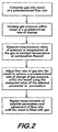
Figure 2 is a flow chart illustrating a method for filling a vessel with a gas according to the invention. -
Figure 1 shows, in schematic form, anapparatus 10 for filling avessel 12 with agas 14.Apparatus 10 comprises asource 16 ofgas 14. Thegas 14 may be stored as aliquid 15 or as thegas 14 at the source.Source 16 is connected in fluid communication with theinlet 18 of a fluid compressing means 20 by aconduit 22. The fluid compressing means 20 may comprise a variable mass flow rate pump or compressor as appropriate depending upon whether a liquid or gaseous fluid is supplied to theinlet 18. A variable mass flow rate compressor or pump may be used for liquids, whereas a variable mass flow rate compressor is used for gas fed to the inlet. The mass flow rate for these pumps and compressors is varied typically by varying the speed of the pump or compressor. - Flow of fluid (liquid 15 or gas 14) from
source 16 to the compressingmeans inlet 18 is controlled by avalve 24 positioned within theconduit 22 between the source and the compressing means. Compressing means 20 has anoutlet 26 which may be connected in fluid communication with thevessel 12 using aconduit 28. Ifliquid 15 is supplied from the compressing means 20 to theconduit 28 then avaporizer 29 is in fluid communication with theconduit 28 to change the state of the fluid to thegas 14. For practical applications theconduit 28 has a coupling 30 which is sealingly connectable to and disconnectable from thevessel 12. Flow ofliquid 15 orgas 14 from the compressing meansoutlet 26 may be controlled by avalve 32 in theconduit 28. Thesource 16 may also be connected to the vessel directly using aconduit 34. Avalve 36 in theconduit 34 is used to control flow ofgas 14 directly from thesource 16 to thevessel 12. Note thatconduit 34 may share the coupling 30 withconduit 28 for connection to thevessel 12. - The apparatus comprises one or more pressure transducers and may comprise one or more temperature transducers, for example,
pressure transducer 38 which measures the gas pressure supplied from the source inconduit 22,pressure transducers inlet 18 andoutlet 26, respectively, of the compressingmeans 20, andpressure transducer 44, which measures the gas pressure withinconduits vessel 12 and is at least present in the apparatus. Temperature transducers includetransducer 46, which measures the ambient temperature surrounding thevessel 12,transducer 48, which measures the temperature of the gas within thevessel 12, andtransducer 50, which measures the temperature of the gas withinconduits vessel 12. Each pressure transducer 38, 40, 42 and 44 generates electrical signals indicative of pressure at their respective measurement points. Similarly thetemperature transducers vessel 12, by measuring the temperature on the outside surface of the vessel, and the pressure in a conduit hydraulically connected to the vessel. It is further understood that every transducer disclosed herein is not necessarily used simultaneously in the apparatus, the exemplary embodiment shown inFigure 1 illustrates several possible configurations which may have a single transducer or combinations of transducers. - The signals generated by the transducers are transmitted to a
controller 52 which is also in communication withvalves controller 52, which may be for example, a programmable logic controller or other microprocessor based device, runs resident software and uses the signals from the transducers in a feed-back loop to open and close the valves and vary the flow rate of the compressing means (for example by varying its speed) according to an algorithm to adjust the flow rate ofgas 14 to thevessel 12 to increase the gas pressure within the vessel at a predetermined rate of change as described below. Auser interface 54, for example, a keyboard and display monitor, provides communication with the controller permitting theapparatus 10 to be operated to dispense gas from the source to the vessel. - In a practical embodiment the
apparatus 10 may serve as a fueling station for dispensing hydrogen fuel to vehicles, the fuel tank comprising thevessel 12. Vehicle tanks have a maximum allowed pressure of about 875 bar. It is desired to maintain the vessel at or below 85°C to avoid overheating. In such a station thegas source 16 comprises a liquid hydrogen storage tank having a capacity between about 5,700 liters and about 171,000 liters. Hydrogen gas is stored in the reservoir at a pressure between about 0 and about 90 MPa. (Alternately, thegas source 16 may comprise, for example, a steam methane reformer, an electrolysis apparatus or a hydrogen pipeline.) The valves may be pneumatic plug valves which are actuatable by the controller. The pressure transducers may be, for example, piezo-electric transducers. The temperature transducers may comprise thermistors. The compressing means operates to provide a mass flow rate variable between about 0.1 and about 10 kg/min. -
Figure 2 provides a flow chart describing an exemplary mode of operation of the apparatus. The exemplary mode described herein assumes thegas 14 is supplied from thesource 16. Operation wherein the liquid 15 is supplied from the source is substantially similar to the operation described herein and is not described separately, it being understood that the liquid 15 is eventually vaporized before enteringvessel 12. - With reference also to
Figure 1 , the coupling 30 is connected to thevessel 12 and a user activates the apparatus with theinterface 54.Valve 24 is opened providinggas 14 from thesource 16 to the compressing means 20.Valve 32 is opened providing gas from the compressing means to thevessel 12. The compressing means is started and begins compressinggas 14 intovessel 12 at a predetermined flow rate. One or more of the aforementioned transducers, but atleast transducer 44, measures the instantaneous value of a selected parameter or paramters (pressure or temperature of the gas, or ambient temperature, or combinations thereof) and generates signals indicative of that value or values. The signals are transmitted to thecontroller 52. Signal transmission, symbolized by the dotted lines inFigure 1 , may be over wires or wirelessly via a radio frequency link. Using the measured values of the parameter or parameters, the controller adjusts the compressing means' flow rate (for example, by adjusting its speed of operation) to increase the gas pressure within the vessel at a predetermined rate of change, known as the pressure rise rate, which will fill the vessel in a predetermined amount of time without overheating the vessel. During filling, the parameter measurements are repeated periodically so that the compressing means' flow rate may be continuously adjusted to take into account the changing pressure within the vessel. The controller halts the flow of gas to the vessel once it is filled to capacity. Thevalves - Various parameters and associated algorithms may be used by the controller to achieve the desired gas pressure change rate within the
vessel 12. For example, the gas pressure may be increased at a constant rate. For practical applications, for example for hydrogen gas filling a fuel tank, the constant increase rate may range between about 2.5MPa/min and about 35 MPa/min. In another algorithm the gas pressure in the vessel increases at an increasing rate. There is also the possibility to increase the pressure at a decreasing rate. - In one embodiment, the controller receives pressure measurements from the
pressure transducer 44 which measures values of the gas pressure within thevessel 12. The controller adjusts the compressing means' flow rate using the gas pressure values to achieve and maintain the desired pressure rise rate according to the feedback relationship:
Wherein: - Compressing Means' Flow Rate(n) is the actual volume flow rate at which the compressor or pump is moving fluid and is proportional to the speed at which a compressor or pump is run during the just completed time interval;
- Compressing Means' Flow Rate(n+1) is the actual volume flow rate at which the compressor or pump is moving fluid and is proportional to the speed at which a compressor or pump is run during the next time interval;
- Target Pressure Rise Rate is the desired pressure rise rate based on current conditions and filling strategy;
- Measured Pressure Rise Rate is the actual pressure rise measured during the just completed time interval; and
- K is the gain, or the rate at which the controller responds to stimulus.
- The compressing means' flow rate may be measured as a mass flow rate in grams/second and the pressure rise rates may be measured in MPa/min. This yields the units associated with the gain K as grams/second per MPa/min for consistency of the functional relationship. The gain K will be specific to a particular apparatus and is determined experimentally consistent with control system practices.
- The controller may also receive temperature measurements from the
temperature transducer 48 which measures values of the gas temperature within thevessel 12. The controller adjusts the compressing means' flow rate using the gas temperature values, for example based upon the functional relation: - When gas temperature within the vessel is less than 65.6°C the pressure rise rate is maintained at 35 MPa/min; when the gas temperature in the vessel exceeds 65.6°C the pressure rise rate is reduced according to the formula: pressure rise rate =(85-gas temperature)x0.555.
- The controller may also receive temperature measurements from the
temperature transducer 46 which measures ambient temperature values surrounding thevessel 12. The controller adjusts the compressing means' flow rate using the ambient temperature values, for example based upon the functional relation: - If ambient temperature < 15°C then the pressure rise rate = 10 MPa/min; if 15°< ambient temperature < 30°C then the pressure rise rate =7.5 MPa/min; if ambient temperature > 30°C then pressure rise rate = 5 MPa/min.
- The controller may also receive temperature measurements from the
temperature transducer 50 which measures values of the gas temperature before it is compressed into thevessel 12. The controller adjusts the compressing means' flow rate using the gas temperature values, for example based upon the functional relation: - If gas temperature < 15°C then the pressure rise rate = 10 MPa/min; if 15°< gas temperature < 30°C then the pressure rise rate =7.5 MPa/min; if gas temperature > 30°C then the pressure rise rate = 5 MPa/min.
- When the
gas source 16 comprises a reservoir of sufficient pressure and capacity, for example at a pressure between about 15 MPa and about 70 MPa and a capacity between about 40 liters and about 1,000 liters, it is feasible to initially fill thevessel 12 by coupling thesource 16 directly to the vessel. As shown inFigure 1 , once the coupling 30 is connected to thevessel 12 thecontroller 52 first opens thevalve 36 allowing gas to flow from thesource 16 directly to thevessel 12 until the gas pressure within the vessel equalizes with the gas pressure of the source. The controller then closesvalve 36 and opens the valves and starts the compressing means as described above to fill the vessel by increasing the gas pressure at a predetermined rate of change. - The method and apparatus according to the invention allows gas vessels to be filled safely and in a reasonable period of time without the fear of overheating and its consequences.
Claims (16)
- A method of filling a vessel (12) with a gas at a predetermined rise rate of gas pressure, said method comprising:(a) compressing said gas into said vessel (12) using a compressing means (20);(b) measuring an instantaneous value of gas pressure within the vessel (12);(c) generating electrical signals indicative of the instantaneous value of the gas pressure within the vessel (12);(d) transmitting the electrical signals to a controller (52);
characterized by
compressing said gas in step (a) into said vessel (12) at a predetermined flow rate using the compressing means (20) having a variable mass flow rate;(e) using the electrical signals to vary the flow rate of the compressing means (20) according to an algorithm used by the controller (52) to adjust said flow rate of said gas into said vessel (12) to achieve said predetermined rise rate of said gas pressure;
and(f) repeating steps (b) through (e) until said vessel (12) is filled with said gas. - A method according to Claim 1, wherein said predetermined rise rate comprises a constant rate of change.
- A method according to Claim 1, wherein said predetermined rise rate comprises a rate of change that increases at an increasing rate.
- A method according to Claim 1, wherein said predetermined rise rate comprises a rate of change that increases as a decreasing rate.
- A method according to Claim 1, wherein said flow rate is provided according to the relation: Compressing Means' Flow Rate(n+1)=Compressing Means' Flow Rate(n)+(Target Pressure Rise Rate - Measured Pressure Rise Rate) x K, wherein K is a gain for controller (52).
- A method according to any one of the preceding Claims further comprising measuring the instantaneous gas temperature within said vessel (12), said gas temperature within said vessel (12) being used to adjust said flow rate to achieve said predetermined rise rate of said gas pressure within said vessel (12).
- A method according to Claim 6, wherein said predetermined rise rate of said gas pressure within said vessel (12) is maintained at 35 MPa/min when said gas temperature within said vessel (12) is less than 65.6°C, and when said gas temperature in said vessel (12) exceeds 65.6°C said pressure rise rate is reduced according to the formula: pressure rise rate = (85 [°C] - gas temperature [°C]) x 0.555 [MPa/min °C].
- A method according to any one of the preceding Claims further comprising measuring the ambient temperature surrounding said vessel (12), said ambient temperature being used to adjust said flow rate to achieve said predetermined rise rate of said gas pressure within said vessel (12).
- A method according to Claim 8, wherein if said ambient temperature is less than 15°C then the predetermined rise rate is maintained at 10 MPa/min, and if said ambient temperature is greater than 15°C and less than 30°C, then the predetermined rise rate is maintained at 7.5 MPa/min, and if said ambient temperature is greater than 30°C then said predetermined rise rate is maintained at 5 MPa/min.
- A method according to any one of the preceding Claims further comprising measuring the temperature of said gas before compressing said gas into said vessel (12), said temperature of said gas before said compressing into said vessel (12) being used to adjust said flow rate to achieve said predetermined rise rate of said gas pressure within said vessel (12).
- A method according to Claim 10, wherein if said gas temperature is less than 15°C then said predetermined rise rate is maintained at 10 MPa/min, and if said gas temperature is greater than 15°C and less than 30°C then said predetermined rise rate is maintained at 7.5 MPa/min, and if said gas temperature is greater than 30°C then said predetermined rise rate is maintained at 5 MPa/min.
- A method according to any one of the preceding Claims, further comprising:providing a reservoir containing said gas at a first gas temperature and a first gas pressure;flowing gas from said reservoir into said vessel (12) until gas pressure within said vessel (12) is equal to a second gas pressure, said second gas pressure being substantially equal to said gas pressure within said reservoir.
- An apparatus (10) for filling a vessel (12) with a gas, said apparatus (10) comprising:a source (16) of said gas;a compressing means (20) for compressing said gas, said compressing means (20) having an inlet (18) and an outlet (26);a first conduit (22) connected between said source (16) and said inlet (18);a second conduit (28) connectable between said outlet (26) and said vessel (12);a controller (52); anda transducer (44) measuring the value of gas pressure within the vessel (12);characterized by:said compressing means (20) having a variable mass flow rate;said controller (52) controlling said mass flow rate of said compressing means (20); andsaid controller (52) receiving electrical signals from said transducer (44), said controller (52) using said electrical signals to control the mass flow rate of said compressing means (20) to increase the gas pressure within the vessel (12) at a predetermined rate of change.
- An apparatus (10) according to Claim 13, further comprising:a first valve (36) positioned within a third conduit (34) controlling gas flow between said source (16) and said vessel (12);a second valve (24) positioned within said first conduit (22) controlling gas flow between said source (16) and said compressing means inlet (18);a third valve (32) positioned within said second conduit (28) controlling gas flow between said compressing means outlet (26) and said vessel (12), said controller (52) controlling said first (36), second (24) and third (32) valves.
- An apparatus according to any one of the Claims 13 to 14 further comprising at least one of a temperature transducer (48) measuring gas temperature within said vessel (12), a temperature transducer (50) measuring gas temperature before entering said vessel (12), and a temperature transducer (46) measuring ambient temperature surrounding said vessel (12).
- An apparatus according to any one of Claims 13 to 15, wherein said compressing means (20) is selected from the group consisting of a pump and a compressor.
Applications Claiming Priority (1)
| Application Number | Priority Date | Filing Date | Title |
|---|---|---|---|
| US12/034,284 US8365777B2 (en) | 2008-02-20 | 2008-02-20 | Compressor fill method and apparatus |
Publications (3)
| Publication Number | Publication Date |
|---|---|
| EP2093475A1 EP2093475A1 (en) | 2009-08-26 |
| EP2093475B1 true EP2093475B1 (en) | 2014-03-19 |
| EP2093475B2 EP2093475B2 (en) | 2018-12-05 |
Family
ID=40613043
Family Applications (1)
| Application Number | Title | Priority Date | Filing Date |
|---|---|---|---|
| EP09153260.6A Active EP2093475B2 (en) | 2008-02-20 | 2009-02-20 | Compressor fill method and apparatus |
Country Status (5)
| Country | Link |
|---|---|
| US (1) | US8365777B2 (en) |
| EP (1) | EP2093475B2 (en) |
| CA (1) | CA2653819C (en) |
| ES (1) | ES2456295T5 (en) |
| PT (1) | PT2093475E (en) |
Families Citing this family (47)
| Publication number | Priority date | Publication date | Assignee | Title |
|---|---|---|---|---|
| CN101237488A (en) * | 2008-02-22 | 2008-08-06 | 华为技术有限公司 | Device and method for realizing CRBT service and device for getting CRBT file |
| JP5474436B2 (en) * | 2009-07-30 | 2014-04-16 | トヨタ自動車株式会社 | Gas filling system |
| JP5489573B2 (en) * | 2009-07-30 | 2014-05-14 | トヨタ自動車株式会社 | Gas filling system and gas filling device |
| WO2011058782A1 (en) * | 2009-11-16 | 2011-05-19 | トヨタ自動車株式会社 | Gas filling device and gas filling method |
| JP5328617B2 (en) * | 2009-11-18 | 2013-10-30 | トヨタ自動車株式会社 | Gas filling system, gas filling method, vehicle |
| US20110169259A1 (en) * | 2010-01-14 | 2011-07-14 | Gm Global Technology Operations, Inc. | Tube fitting connection |
| JP5261408B2 (en) * | 2010-01-25 | 2013-08-14 | トヨタ自動車株式会社 | Fuel gas station, fuel gas filling system, and fuel gas supply method |
| US8783303B2 (en) * | 2010-04-21 | 2014-07-22 | Ryan HARTY | Method and system for tank refilling |
| US9347612B2 (en) | 2010-04-21 | 2016-05-24 | Honda Motor Co., Ltd. | Method and system for tank refilling using active fueling speed control |
| US9605804B2 (en) | 2010-04-21 | 2017-03-28 | Honda Motor Co., Ltd. | Method and system for tank refilling using active fueling speed control |
| US9212783B2 (en) | 2010-04-21 | 2015-12-15 | Honda Motor Co., Ltd. | Method and system for tank refilling |
| US9347614B2 (en) | 2010-04-21 | 2016-05-24 | Honda Motor Co., Ltd. | Method and system for tank refilling using active fueling speed control |
| US9458968B2 (en) * | 2011-03-11 | 2016-10-04 | Shell Oil Company | Hydrogen dispensing process and system |
| US9234627B2 (en) * | 2011-07-08 | 2016-01-12 | Jose A. Cajiga | System, apparatus and method for the cold-weather storage of gaseous fuel |
| US9759383B2 (en) | 2011-07-08 | 2017-09-12 | Capat Llc | Multi-stage compression and storage system for use with municipal gaseous supply |
| EP2788215B1 (en) * | 2011-12-07 | 2020-01-15 | Agility Fuel Systems LLC | Systems and methods for monitoring and controlling fuel systems |
| JP5746962B2 (en) | 2011-12-20 | 2015-07-08 | 株式会社神戸製鋼所 | Gas supply method and gas supply apparatus |
| US20130213521A1 (en) * | 2012-02-20 | 2013-08-22 | Wendell W. Isom | Mobile filling station |
| US20130306570A1 (en) * | 2012-05-16 | 2013-11-21 | David A. Potts | Pressurized Gas Lifting and Gas Rejuvenation |
| US8834727B2 (en) | 2012-05-16 | 2014-09-16 | David A. Potts | Pressurized gas lifting and gas rejuvenation |
| DE102013002431A1 (en) * | 2013-02-12 | 2014-08-14 | Linde Aktiengesellschaft | Filling of storage containers with a gaseous, pressurized medium, in particular hydrogen |
| WO2014149930A1 (en) * | 2013-03-15 | 2014-09-25 | Honda Motor Co., Ltd. | Improved method and system for tank refilling |
| US9586806B2 (en) * | 2013-03-15 | 2017-03-07 | Honda Motor Co., Ltd. | Hydrogen fuel dispenser with pre-cooling circuit |
| US9279541B2 (en) * | 2013-04-22 | 2016-03-08 | Air Products And Chemicals, Inc. | Method and system for temperature-controlled gas dispensing |
| GB2516959B (en) * | 2013-08-08 | 2018-01-10 | Intelligent Energy Ltd | Gas filling apparatus and method |
| WO2015031482A2 (en) * | 2013-08-28 | 2015-03-05 | Nuvera Fuel Cells, Inc. | Integrated electrochemical compressor and cascade storage method and system |
| WO2015065996A1 (en) * | 2013-10-28 | 2015-05-07 | Alternative Fuel Containers, Llc | Fuel gas tank filling system and method |
| US9605805B2 (en) * | 2013-11-04 | 2017-03-28 | Trillium Transportation Fuels, Llc | Active pressure and flow regulation system |
| JP2015105709A (en) * | 2013-11-29 | 2015-06-08 | 株式会社神戸製鋼所 | Gas charging device, and gas charging method |
| US9404620B2 (en) * | 2014-09-30 | 2016-08-02 | Air Products And Chemicals, Inc. | Reducing pressure spikes during hydrogen dispensing |
| CN107683385B (en) * | 2015-03-13 | 2020-02-07 | 先能驹解决有限公司 | Pressure vessel for increasing gas storage capacity |
| WO2017040550A1 (en) * | 2015-08-30 | 2017-03-09 | The Regents Of The University Of California | Gas fueling systems and methods with minimum and/or no cooling |
| US10077998B2 (en) | 2015-09-14 | 2018-09-18 | Honda Motor Co., Ltd. | Hydrogen fueling with integrity checks |
| US10919400B2 (en) * | 2017-12-15 | 2021-02-16 | Honda Motor Co., Ltd. | Systems for validating a formula for dispensing hydrogen and methods thereof |
| DK179886B1 (en) * | 2018-03-07 | 2019-08-27 | Nel Hydrogen A/S | A hydrogen refueling station and a method for controlling the hydrogen refueling station |
| FR3082277B1 (en) * | 2018-06-07 | 2021-11-19 | Air Liquide | DEVICE AND A PROCESS FOR FILLING A PRESSURIZED GAS TANK (S) |
| CN110939858B (en) * | 2018-09-21 | 2022-04-12 | 国家能源投资集团有限责任公司 | Hydrogenation station control method and device and hydrogenation station |
| US11313514B2 (en) | 2018-12-04 | 2022-04-26 | Honda Motor Co., Ltd. | Method and system for tank refueling using dispenser and nozzle readings |
| US11339926B2 (en) | 2018-12-05 | 2022-05-24 | Honda Motor Co., Ltd. | Methods and systems for improving hydrogen refueling |
| JP6600430B1 (en) * | 2019-02-01 | 2019-10-30 | 岩谷産業株式会社 | Inspection device for hydrogen gas dispenser |
| US11346348B2 (en) * | 2019-09-04 | 2022-05-31 | Advanced Flow Solutions, Inc. | Liquefied gas unloading and deep evacuation system |
| DE102019134643A1 (en) * | 2019-12-17 | 2021-06-17 | Bayerische Motoren Werke Aktiengesellschaft | Pressure vessel system and energy supply arrangement |
| CN113494678B (en) * | 2020-03-19 | 2022-10-04 | 广州汽车集团股份有限公司 | Hydrogen filling control method and system |
| US20230137335A1 (en) | 2021-10-29 | 2023-05-04 | Air Products And Chemicals, Inc. | Hydrogen storage and dispensing apparatus and method |
| US20230287875A1 (en) | 2022-03-08 | 2023-09-14 | Air Products And Chemicals, Inc. | Apparatus and method for cryogenic pump cooldown |
| GB2618574A (en) * | 2022-05-10 | 2023-11-15 | Logan Energy Ltd | Hydrogen pressurizing rig |
| US11946599B2 (en) | 2022-06-08 | 2024-04-02 | Air Products And Chemicals, Inc. | Apparatus and method for hydrogen fuel dispensing |
Family Cites Families (44)
| Publication number | Priority date | Publication date | Assignee | Title |
|---|---|---|---|---|
| EP0300222B1 (en) | 1987-07-23 | 1992-08-12 | GebràDer Sulzer Aktiengesellschaft | Filling device for a gaseous-fuel reservoir |
| NZ229839A (en) | 1988-08-15 | 1992-01-29 | Sulzer Ag | Cng refueller with temperature and pressure cut-offs |
| US5409046A (en) * | 1989-10-02 | 1995-04-25 | Swenson; Paul F. | System for fast-filling compressed natural gas powered vehicles |
| NZ242143A (en) | 1991-05-30 | 1994-03-25 | Sulzer Ag | Apparatus for refuelling gas fuel tank; part of pressurised gas tank is load-bearing part for compressor housing |
| US5243821A (en) | 1991-06-24 | 1993-09-14 | Air Products And Chemicals, Inc. | Method and apparatus for delivering a continuous quantity of gas over a wide range of flow rates |
| US5411374A (en) | 1993-03-30 | 1995-05-02 | Process Systems International, Inc. | Cryogenic fluid pump system and method of pumping cryogenic fluid |
| US5454408A (en) * | 1993-08-11 | 1995-10-03 | Thermo Power Corporation | Variable-volume storage and dispensing apparatus for compressed natural gas |
| US5458167A (en) * | 1993-08-12 | 1995-10-17 | R. M. Schultz & Associates, Inc. | Filling system for compressed gas tanks |
| US5351726A (en) | 1993-09-27 | 1994-10-04 | Wagner & Brown, Ltd. | System and method for compressing natural gas and for refueling motor vehicles |
| DE59404467D1 (en) | 1993-11-08 | 1997-12-04 | Burckhardt Ag Maschf | Method and device for the rapid refueling of a pressure container with a gaseous medium |
| US5488978A (en) | 1994-05-02 | 1996-02-06 | Gas Research Institute | Apparatus and method for controlling the charging of NGV cylinders from natural gas refueling stations |
| DE29516989U1 (en) | 1995-10-27 | 1996-01-25 | Preussag Anlagenbau | Gas refueling system |
| JPH09250695A (en) | 1996-03-15 | 1997-09-22 | Sanyo Electric Co Ltd | Natural gas fitting method to on-vehicle gas cylinder |
| US5752552A (en) * | 1996-03-20 | 1998-05-19 | Gas Research Institute | Method and apparatus for dispensing compressed natural gas |
| US5810058A (en) * | 1996-03-20 | 1998-09-22 | Gas Research Institute | Automated process and system for dispensing compressed natural gas |
| DE19643801B4 (en) | 1996-10-30 | 2005-08-25 | Gall, Sieghard, Dr. | Method and device for gas filling a container at a desired filling pressure and / or a desired filling amount |
| US5868176A (en) * | 1997-05-27 | 1999-02-09 | Gas Research Institute | System for controlling the fill of compressed natural gas cylinders |
| US5884488A (en) | 1997-11-07 | 1999-03-23 | Westport Research Inc. | High pressure fuel supply system for natural gas vehicles |
| US5832906A (en) | 1998-01-06 | 1998-11-10 | Westport Research Inc. | Intensifier apparatus and method for supplying high pressure gaseous fuel to an internal combustion engine |
| CA2271450A1 (en) | 1999-05-12 | 2000-11-12 | Stuart Energy Systems Inc. | Hydrogen fuel replenishment process and apparatus |
| JP4490557B2 (en) * | 2000-06-09 | 2010-06-30 | 本田技研工業株式会社 | Rapid hydrogen filling method |
| EP1205704B1 (en) | 2000-11-08 | 2008-03-26 | GreenField AG | Process for filling a vehicle tank with gas |
| DE50113779D1 (en) | 2000-11-08 | 2008-05-08 | Greenfield Ag | Method for filling a vehicle tank with gas |
| DE10218678B4 (en) | 2001-04-27 | 2005-09-08 | Deutsches Zentrum für Luft- und Raumfahrt e.V. | Method for a gas refueling system and device for filling a pressurized gas container |
| US6640556B2 (en) | 2001-09-19 | 2003-11-04 | Westport Research Inc. | Method and apparatus for pumping a cryogenic fluid from a storage tank |
| US6619336B2 (en) | 2002-02-14 | 2003-09-16 | Air Products And Chemicals, Inc. | System and method for dispensing pressurized gas |
| US6779568B2 (en) * | 2002-07-16 | 2004-08-24 | General Hydrogen Corporation | Gas distribution system |
| US6786245B1 (en) * | 2003-02-21 | 2004-09-07 | Air Products And Chemicals, Inc. | Self-contained mobile fueling station |
| US6810924B2 (en) | 2003-03-17 | 2004-11-02 | Praxair Technology, Inc. | Compressed gas stream introduction method and filling station |
| US6792981B1 (en) | 2003-04-09 | 2004-09-21 | Praxair Technology, Inc. | Method and apparatus for filling a pressure vessel having application to vehicle fueling |
| US7490635B2 (en) * | 2003-10-17 | 2009-02-17 | L'air Liquide, Societe Anonyme Pour L'etude Et L'exploitation Des Procedes Georges Claude | Method for filling a pressure vessel with gas |
| JP4643589B2 (en) * | 2003-12-19 | 2011-03-02 | レール・リキード−ソシエテ・アノニム・プール・レテュード・エ・レクスプロワタシオン・デ・プロセデ・ジョルジュ・クロード | Method for filling a compressed gas container with gas |
| US7059364B2 (en) * | 2004-02-12 | 2006-06-13 | Gas Technology Institute | Control method for high-pressure hydrogen vehicle fueling station dispensers |
| US20060180237A1 (en) * | 2005-02-17 | 2006-08-17 | Hoke Bryan C Jr | System and method for dispensing compressed gas |
| US7152637B2 (en) * | 2005-02-17 | 2006-12-26 | Air Products And Chemicals, Inc. | Method and apparatus for dispensing compressed gas |
| US7410348B2 (en) | 2005-08-03 | 2008-08-12 | Air Products And Chemicals, Inc. | Multi-speed compressor/pump apparatus |
| FR2891347B1 (en) † | 2005-09-28 | 2007-11-02 | Air Liquide | METHOD AND DEVICE FOR FILLING A PRESSURIZED GAS IN A RESERVOIR |
| US20070079892A1 (en) * | 2005-10-10 | 2007-04-12 | Cohen Joseph P | Gas filling system |
| JP2007139145A (en) * | 2005-11-22 | 2007-06-07 | Honda Motor Co Ltd | Hydrogen filling station and hydrogen filling method |
| US7568507B2 (en) * | 2005-12-06 | 2009-08-04 | Air Products And Chemicals, Inc. | Diagnostic method and apparatus for a pressurized gas supply system |
| US7328726B2 (en) * | 2006-01-20 | 2008-02-12 | Air Products And Chemicals, Inc. | Ramp rate blender |
| US20070186982A1 (en) * | 2006-02-10 | 2007-08-16 | Cohen Joseph P | Method for dispensing compressed gas |
| US7921883B2 (en) * | 2006-06-07 | 2011-04-12 | Air Products And Chemicals, Inc. | Hydrogen dispenser with user-selectable hydrogen dispensing rate algorithms |
| US8020589B2 (en) * | 2007-01-04 | 2011-09-20 | Air Products And Chemicals, Inc. | Hydrogen dispensing station and method of operating the same |
-
2008
- 2008-02-20 US US12/034,284 patent/US8365777B2/en active Active
-
2009
- 2009-02-12 CA CA2653819A patent/CA2653819C/en active Active
- 2009-02-20 PT PT91532606T patent/PT2093475E/en unknown
- 2009-02-20 EP EP09153260.6A patent/EP2093475B2/en active Active
- 2009-02-20 ES ES09153260T patent/ES2456295T5/en active Active
Also Published As
| Publication number | Publication date |
|---|---|
| EP2093475B2 (en) | 2018-12-05 |
| EP2093475A1 (en) | 2009-08-26 |
| CA2653819A1 (en) | 2009-08-20 |
| ES2456295T5 (en) | 2019-03-08 |
| ES2456295T3 (en) | 2014-04-21 |
| US8365777B2 (en) | 2013-02-05 |
| CA2653819C (en) | 2012-01-03 |
| US20090205745A1 (en) | 2009-08-20 |
| PT2093475E (en) | 2014-04-23 |
Similar Documents
| Publication | Publication Date | Title |
|---|---|---|
| EP2093475B1 (en) | Compressor fill method and apparatus | |
| EP1865248B1 (en) | Hydrogen dispenser with user-selectable hydrogen dispensing rate algorithms | |
| JP5947330B2 (en) | Method and system for dispensing temperature controlled gas | |
| KR101633568B1 (en) | Gas supply method and gas supply equipment | |
| CN102667302B (en) | Gas filling system, gas filling method, and vehicle | |
| CN109538936B (en) | Device equipped with a tank | |
| EP1818597A2 (en) | Method for dispensing compressed gas | |
| JP6864049B2 (en) | Instruments and methods for testing compressed gas distribution stations | |
| JP2002206693A (en) | Method for filling vehicle fuel tank with gas | |
| CN101802480A (en) | Be used to fill the method for pressure gas containers | |
| CN113375043A (en) | Filling device | |
| CN101968160A (en) | Gas dispensation automatic control method and liquefied natural gas vehicle gas dispenser | |
| JP5461791B2 (en) | Gas filling method and gas filling apparatus | |
| JP7256735B2 (en) | Hydrogen filling method | |
| CN216667251U (en) | Unattended LNG (liquefied Natural gas) station | |
| JP4262420B2 (en) | Fuel mixing and filling system | |
| JP2002188797A (en) | Fuel mixing and filling system | |
| EP3620711B1 (en) | Apparatus and method for testing compressed gas dispensing stations | |
| JP2020075654A (en) | vehicle | |
| KR20230130753A (en) | gas filling device | |
| JP2024036224A (en) | gas filling device | |
| CN117651853A (en) | Driving system and method for determining temperature in metering system of driving system | |
| GB2613202A (en) | Method of compressing hydrogen gas, hydrogen gas compressor system and hydrogen gas storage unit | |
| JP2004019829A (en) | Gas supply device |
Legal Events
| Date | Code | Title | Description |
|---|---|---|---|
| PUAI | Public reference made under article 153(3) epc to a published international application that has entered the european phase |
Free format text: ORIGINAL CODE: 0009012 |
|
| AK | Designated contracting states |
Kind code of ref document: A1 Designated state(s): AT BE BG CH CY CZ DE DK EE ES FI FR GB GR HR HU IE IS IT LI LT LU LV MC MK MT NL NO PL PT RO SE SI SK TR |
|
| AX | Request for extension of the european patent |
Extension state: AL BA RS |
|
| 17P | Request for examination filed |
Effective date: 20100219 |
|
| AKX | Designation fees paid |
Designated state(s): AT BE BG CH CY CZ DE DK EE ES FI FR GB GR HR HU IE IS IT LI LT LU LV MC MK MT NL NO PL PT RO SE SI SK TR |
|
| 17Q | First examination report despatched |
Effective date: 20120824 |
|
| REG | Reference to a national code |
Ref country code: DE Ref legal event code: R079 Ref document number: 602009022553 Country of ref document: DE Free format text: PREVIOUS MAIN CLASS: F17C0005060000 Ipc: F17C0009000000 |
|
| RIC1 | Information provided on ipc code assigned before grant |
Ipc: F17C 7/00 20060101ALI20131001BHEP Ipc: F17C 13/02 20060101ALI20131001BHEP Ipc: F17C 5/02 20060101ALI20131001BHEP Ipc: F17C 9/00 20060101AFI20131001BHEP Ipc: F17C 5/00 20060101ALI20131001BHEP Ipc: F17C 6/00 20060101ALI20131001BHEP Ipc: F17C 5/06 20060101ALI20131001BHEP |
|
| GRAP | Despatch of communication of intention to grant a patent |
Free format text: ORIGINAL CODE: EPIDOSNIGR1 |
|
| INTG | Intention to grant announced |
Effective date: 20131111 |
|
| GRAS | Grant fee paid |
Free format text: ORIGINAL CODE: EPIDOSNIGR3 |
|
| GRAA | (expected) grant |
Free format text: ORIGINAL CODE: 0009210 |
|
| STAA | Information on the status of an ep patent application or granted ep patent |
Free format text: STATUS: THE PATENT HAS BEEN GRANTED |
|
| AK | Designated contracting states |
Kind code of ref document: B1 Designated state(s): AT BE BG CH CY CZ DE DK EE ES FI FR GB GR HR HU IE IS IT LI LT LU LV MC MK MT NL NO PL PT RO SE SI SK TR |
|
| REG | Reference to a national code |
Ref country code: GB Ref legal event code: FG4D |
|
| REG | Reference to a national code |
Ref country code: CH Ref legal event code: EP |
|
| REG | Reference to a national code |
Ref country code: IE Ref legal event code: FG4D |
|
| REG | Reference to a national code |
Ref country code: AT Ref legal event code: REF Ref document number: 657913 Country of ref document: AT Kind code of ref document: T Effective date: 20140415 |
|
| REG | Reference to a national code |
Ref country code: ES Ref legal event code: FG2A Ref document number: 2456295 Country of ref document: ES Kind code of ref document: T3 Effective date: 20140421 |
|
| REG | Reference to a national code |
Ref country code: PT Ref legal event code: SC4A Free format text: AVAILABILITY OF NATIONAL TRANSLATION Effective date: 20140414 |
|
| REG | Reference to a national code |
Ref country code: DE Ref legal event code: R096 Ref document number: 602009022553 Country of ref document: DE Effective date: 20140430 |
|
| PG25 | Lapsed in a contracting state [announced via postgrant information from national office to epo] |
Ref country code: NO Free format text: LAPSE BECAUSE OF FAILURE TO SUBMIT A TRANSLATION OF THE DESCRIPTION OR TO PAY THE FEE WITHIN THE PRESCRIBED TIME-LIMIT Effective date: 20140619 Ref country code: LT Free format text: LAPSE BECAUSE OF FAILURE TO SUBMIT A TRANSLATION OF THE DESCRIPTION OR TO PAY THE FEE WITHIN THE PRESCRIBED TIME-LIMIT Effective date: 20140319 |
|
| REG | Reference to a national code |
Ref country code: NL Ref legal event code: VDEP Effective date: 20140319 |
|
| REG | Reference to a national code |
Ref country code: AT Ref legal event code: MK05 Ref document number: 657913 Country of ref document: AT Kind code of ref document: T Effective date: 20140319 |
|
| REG | Reference to a national code |
Ref country code: LT Ref legal event code: MG4D |
|
| PG25 | Lapsed in a contracting state [announced via postgrant information from national office to epo] |
Ref country code: SE Free format text: LAPSE BECAUSE OF FAILURE TO SUBMIT A TRANSLATION OF THE DESCRIPTION OR TO PAY THE FEE WITHIN THE PRESCRIBED TIME-LIMIT Effective date: 20140319 Ref country code: FI Free format text: LAPSE BECAUSE OF FAILURE TO SUBMIT A TRANSLATION OF THE DESCRIPTION OR TO PAY THE FEE WITHIN THE PRESCRIBED TIME-LIMIT Effective date: 20140319 Ref country code: CY Free format text: LAPSE BECAUSE OF FAILURE TO SUBMIT A TRANSLATION OF THE DESCRIPTION OR TO PAY THE FEE WITHIN THE PRESCRIBED TIME-LIMIT Effective date: 20140319 |
|
| PG25 | Lapsed in a contracting state [announced via postgrant information from national office to epo] |
Ref country code: LV Free format text: LAPSE BECAUSE OF FAILURE TO SUBMIT A TRANSLATION OF THE DESCRIPTION OR TO PAY THE FEE WITHIN THE PRESCRIBED TIME-LIMIT Effective date: 20140319 Ref country code: HR Free format text: LAPSE BECAUSE OF FAILURE TO SUBMIT A TRANSLATION OF THE DESCRIPTION OR TO PAY THE FEE WITHIN THE PRESCRIBED TIME-LIMIT Effective date: 20140319 |
|
| PG25 | Lapsed in a contracting state [announced via postgrant information from national office to epo] |
Ref country code: NL Free format text: LAPSE BECAUSE OF FAILURE TO SUBMIT A TRANSLATION OF THE DESCRIPTION OR TO PAY THE FEE WITHIN THE PRESCRIBED TIME-LIMIT Effective date: 20140319 Ref country code: EE Free format text: LAPSE BECAUSE OF FAILURE TO SUBMIT A TRANSLATION OF THE DESCRIPTION OR TO PAY THE FEE WITHIN THE PRESCRIBED TIME-LIMIT Effective date: 20140319 Ref country code: BG Free format text: LAPSE BECAUSE OF FAILURE TO SUBMIT A TRANSLATION OF THE DESCRIPTION OR TO PAY THE FEE WITHIN THE PRESCRIBED TIME-LIMIT Effective date: 20140619 Ref country code: IS Free format text: LAPSE BECAUSE OF FAILURE TO SUBMIT A TRANSLATION OF THE DESCRIPTION OR TO PAY THE FEE WITHIN THE PRESCRIBED TIME-LIMIT Effective date: 20140719 Ref country code: RO Free format text: LAPSE BECAUSE OF FAILURE TO SUBMIT A TRANSLATION OF THE DESCRIPTION OR TO PAY THE FEE WITHIN THE PRESCRIBED TIME-LIMIT Effective date: 20140319 Ref country code: BE Free format text: LAPSE BECAUSE OF FAILURE TO SUBMIT A TRANSLATION OF THE DESCRIPTION OR TO PAY THE FEE WITHIN THE PRESCRIBED TIME-LIMIT Effective date: 20140319 Ref country code: CZ Free format text: LAPSE BECAUSE OF FAILURE TO SUBMIT A TRANSLATION OF THE DESCRIPTION OR TO PAY THE FEE WITHIN THE PRESCRIBED TIME-LIMIT Effective date: 20140319 |
|
| PG25 | Lapsed in a contracting state [announced via postgrant information from national office to epo] |
Ref country code: AT Free format text: LAPSE BECAUSE OF FAILURE TO SUBMIT A TRANSLATION OF THE DESCRIPTION OR TO PAY THE FEE WITHIN THE PRESCRIBED TIME-LIMIT Effective date: 20140319 Ref country code: SK Free format text: LAPSE BECAUSE OF FAILURE TO SUBMIT A TRANSLATION OF THE DESCRIPTION OR TO PAY THE FEE WITHIN THE PRESCRIBED TIME-LIMIT Effective date: 20140319 Ref country code: PL Free format text: LAPSE BECAUSE OF FAILURE TO SUBMIT A TRANSLATION OF THE DESCRIPTION OR TO PAY THE FEE WITHIN THE PRESCRIBED TIME-LIMIT Effective date: 20140319 |
|
| REG | Reference to a national code |
Ref country code: DE Ref legal event code: R082 Ref document number: 602009022553 Country of ref document: DE Representative=s name: ANDREA SOMMER PATENTANWAELTE PARTNERSCHAFT MBB, DE Ref country code: DE Ref legal event code: R082 Ref document number: 602009022553 Country of ref document: DE Ref country code: DE Ref legal event code: R082 Ref document number: 602009022553 Country of ref document: DE Representative=s name: ANDRAE WESTENDORP PATENTANWAELTE PARTNERSCHAFT, DE |
|
| REG | Reference to a national code |
Ref country code: DE Ref legal event code: R026 Ref document number: 602009022553 Country of ref document: DE |
|
| PLBI | Opposition filed |
Free format text: ORIGINAL CODE: 0009260 |
|
| 26 | Opposition filed |
Opponent name: L'AIR LIQUIDE SOCIETE ANONYME POUR L'ETUDE ET L'EX Effective date: 20141205 |
|
| PLAF | Information modified related to communication of a notice of opposition and request to file observations + time limit |
Free format text: ORIGINAL CODE: EPIDOSCOBS2 |
|
| REG | Reference to a national code |
Ref country code: FR Ref legal event code: PLFP Year of fee payment: 7 |
|
| PLAX | Notice of opposition and request to file observation + time limit sent |
Free format text: ORIGINAL CODE: EPIDOSNOBS2 |
|
| PG25 | Lapsed in a contracting state [announced via postgrant information from national office to epo] |
Ref country code: DK Free format text: LAPSE BECAUSE OF FAILURE TO SUBMIT A TRANSLATION OF THE DESCRIPTION OR TO PAY THE FEE WITHIN THE PRESCRIBED TIME-LIMIT Effective date: 20140319 |
|
| REG | Reference to a national code |
Ref country code: DE Ref legal event code: R026 Ref document number: 602009022553 Country of ref document: DE Effective date: 20141205 |
|
| PLAF | Information modified related to communication of a notice of opposition and request to file observations + time limit |
Free format text: ORIGINAL CODE: EPIDOSCOBS2 |
|
| PG25 | Lapsed in a contracting state [announced via postgrant information from national office to epo] |
Ref country code: SI Free format text: LAPSE BECAUSE OF FAILURE TO SUBMIT A TRANSLATION OF THE DESCRIPTION OR TO PAY THE FEE WITHIN THE PRESCRIBED TIME-LIMIT Effective date: 20140319 |
|
| PLBB | Reply of patent proprietor to notice(s) of opposition received |
Free format text: ORIGINAL CODE: EPIDOSNOBS3 |
|
| PG25 | Lapsed in a contracting state [announced via postgrant information from national office to epo] |
Ref country code: LU Free format text: LAPSE BECAUSE OF FAILURE TO SUBMIT A TRANSLATION OF THE DESCRIPTION OR TO PAY THE FEE WITHIN THE PRESCRIBED TIME-LIMIT Effective date: 20150220 |
|
| REG | Reference to a national code |
Ref country code: CH Ref legal event code: PL |
|
| PG25 | Lapsed in a contracting state [announced via postgrant information from national office to epo] |
Ref country code: LI Free format text: LAPSE BECAUSE OF NON-PAYMENT OF DUE FEES Effective date: 20150228 Ref country code: MC Free format text: LAPSE BECAUSE OF FAILURE TO SUBMIT A TRANSLATION OF THE DESCRIPTION OR TO PAY THE FEE WITHIN THE PRESCRIBED TIME-LIMIT Effective date: 20140319 Ref country code: CH Free format text: LAPSE BECAUSE OF NON-PAYMENT OF DUE FEES Effective date: 20150228 |
|
| REG | Reference to a national code |
Ref country code: IE Ref legal event code: MM4A |
|
| REG | Reference to a national code |
Ref country code: FR Ref legal event code: PLFP Year of fee payment: 8 |
|
| PG25 | Lapsed in a contracting state [announced via postgrant information from national office to epo] |
Ref country code: IE Free format text: LAPSE BECAUSE OF NON-PAYMENT OF DUE FEES Effective date: 20150220 |
|
| PLAY | Examination report in opposition despatched + time limit |
Free format text: ORIGINAL CODE: EPIDOSNORE2 |
|
| PG25 | Lapsed in a contracting state [announced via postgrant information from national office to epo] |
Ref country code: GR Free format text: LAPSE BECAUSE OF FAILURE TO SUBMIT A TRANSLATION OF THE DESCRIPTION OR TO PAY THE FEE WITHIN THE PRESCRIBED TIME-LIMIT Effective date: 20140620 |
|
| PLAH | Information related to despatch of examination report in opposition + time limit modified |
Free format text: ORIGINAL CODE: EPIDOSCORE2 |
|
| PLBC | Reply to examination report in opposition received |
Free format text: ORIGINAL CODE: EPIDOSNORE3 |
|
| PG25 | Lapsed in a contracting state [announced via postgrant information from national office to epo] |
Ref country code: MT Free format text: LAPSE BECAUSE OF FAILURE TO SUBMIT A TRANSLATION OF THE DESCRIPTION OR TO PAY THE FEE WITHIN THE PRESCRIBED TIME-LIMIT Effective date: 20140319 |
|
| REG | Reference to a national code |
Ref country code: FR Ref legal event code: PLFP Year of fee payment: 9 |
|
| PG25 | Lapsed in a contracting state [announced via postgrant information from national office to epo] |
Ref country code: HU Free format text: LAPSE BECAUSE OF FAILURE TO SUBMIT A TRANSLATION OF THE DESCRIPTION OR TO PAY THE FEE WITHIN THE PRESCRIBED TIME-LIMIT; INVALID AB INITIO Effective date: 20090220 |
|
| PG25 | Lapsed in a contracting state [announced via postgrant information from national office to epo] |
Ref country code: TR Free format text: LAPSE BECAUSE OF FAILURE TO SUBMIT A TRANSLATION OF THE DESCRIPTION OR TO PAY THE FEE WITHIN THE PRESCRIBED TIME-LIMIT Effective date: 20140319 |
|
| REG | Reference to a national code |
Ref country code: FR Ref legal event code: PLFP Year of fee payment: 10 |
|
| PG25 | Lapsed in a contracting state [announced via postgrant information from national office to epo] |
Ref country code: MK Free format text: LAPSE BECAUSE OF FAILURE TO SUBMIT A TRANSLATION OF THE DESCRIPTION OR TO PAY THE FEE WITHIN THE PRESCRIBED TIME-LIMIT Effective date: 20140319 |
|
| REG | Reference to a national code |
Ref country code: DE Ref legal event code: R082 Ref document number: 602009022553 Country of ref document: DE Representative=s name: ANDREA SOMMER PATENTANWAELTE PARTNERSCHAFT MBB, DE Ref country code: DE Ref legal event code: R082 Ref document number: 602009022553 Country of ref document: DE |
|
| REG | Reference to a national code |
Ref country code: DE Ref legal event code: R082 Ref document number: 602009022553 Country of ref document: DE Representative=s name: ANDREA SOMMER PATENTANWAELTE PARTNERSCHAFT MBB, DE |
|
| PUAH | Patent maintained in amended form |
Free format text: ORIGINAL CODE: 0009272 |
|
| STAA | Information on the status of an ep patent application or granted ep patent |
Free format text: STATUS: PATENT MAINTAINED AS AMENDED |
|
| 27A | Patent maintained in amended form |
Effective date: 20181205 |
|
| AK | Designated contracting states |
Kind code of ref document: B2 Designated state(s): AT BE BG CH CY CZ DE DK EE ES FI FR GB GR HR HU IE IS IT LI LT LU LV MC MK MT NL NO PL PT RO SE SI SK TR |
|
| REG | Reference to a national code |
Ref country code: DE Ref legal event code: R102 Ref document number: 602009022553 Country of ref document: DE |
|
| REG | Reference to a national code |
Ref country code: ES Ref legal event code: DC2A Ref document number: 2456295 Country of ref document: ES Kind code of ref document: T5 Effective date: 20190308 |
|
| PGFP | Annual fee paid to national office [announced via postgrant information from national office to epo] |
Ref country code: GB Payment date: 20221230 Year of fee payment: 15 |
|
| PGFP | Annual fee paid to national office [announced via postgrant information from national office to epo] |
Ref country code: FR Payment date: 20230110 Year of fee payment: 15 Ref country code: ES Payment date: 20230314 Year of fee payment: 15 |
|
| PGFP | Annual fee paid to national office [announced via postgrant information from national office to epo] |
Ref country code: PT Payment date: 20230219 Year of fee payment: 15 Ref country code: IT Payment date: 20230110 Year of fee payment: 15 Ref country code: DE Payment date: 20221229 Year of fee payment: 15 |
|
| P01 | Opt-out of the competence of the unified patent court (upc) registered |
Effective date: 20230523 |
|
| PGFP | Annual fee paid to national office [announced via postgrant information from national office to epo] |
Ref country code: ES Payment date: 20240305 Year of fee payment: 16 |