EP2093465A1 - Scheibendichtung - Google Patents
Scheibendichtung Download PDFInfo
- Publication number
- EP2093465A1 EP2093465A1 EP09153180A EP09153180A EP2093465A1 EP 2093465 A1 EP2093465 A1 EP 2093465A1 EP 09153180 A EP09153180 A EP 09153180A EP 09153180 A EP09153180 A EP 09153180A EP 2093465 A1 EP2093465 A1 EP 2093465A1
- Authority
- EP
- European Patent Office
- Prior art keywords
- filler
- recesses
- window
- sealing frame
- seal according
- Prior art date
- Legal status (The legal status is an assumption and is not a legal conclusion. Google has not performed a legal analysis and makes no representation as to the accuracy of the status listed.)
- Granted
Links
- 238000007789 sealing Methods 0.000 title claims abstract description 28
- 239000000945 filler Substances 0.000 claims abstract description 34
- 230000007704 transition Effects 0.000 claims abstract description 14
- 238000006073 displacement reaction Methods 0.000 description 1
- 239000000463 material Substances 0.000 description 1
- 239000007769 metal material Substances 0.000 description 1
Images

Classifications
-
- F—MECHANICAL ENGINEERING; LIGHTING; HEATING; WEAPONS; BLASTING
- F16—ENGINEERING ELEMENTS AND UNITS; GENERAL MEASURES FOR PRODUCING AND MAINTAINING EFFECTIVE FUNCTIONING OF MACHINES OR INSTALLATIONS; THERMAL INSULATION IN GENERAL
- F16J—PISTONS; CYLINDERS; SEALINGS
- F16J15/00—Sealings
- F16J15/02—Sealings between relatively-stationary surfaces
- F16J15/021—Sealings between relatively-stationary surfaces with elastic packing
- F16J15/022—Sealings between relatively-stationary surfaces with elastic packing characterised by structure or material
- F16J15/024—Sealings between relatively-stationary surfaces with elastic packing characterised by structure or material the packing being locally weakened in order to increase elasticity
-
- F—MECHANICAL ENGINEERING; LIGHTING; HEATING; WEAPONS; BLASTING
- F15—FLUID-PRESSURE ACTUATORS; HYDRAULICS OR PNEUMATICS IN GENERAL
- F15B—SYSTEMS ACTING BY MEANS OF FLUIDS IN GENERAL; FLUID-PRESSURE ACTUATORS, e.g. SERVOMOTORS; DETAILS OF FLUID-PRESSURE SYSTEMS, NOT OTHERWISE PROVIDED FOR
- F15B15/00—Fluid-actuated devices for displacing a member from one position to another; Gearing associated therewith
- F15B15/08—Characterised by the construction of the motor unit
- F15B15/12—Characterised by the construction of the motor unit of the oscillating-vane or curved-cylinder type
Definitions
- the invention relates to a window seal according to the preamble of patent claim 1.
- a disc seal for a swing motor which consists of a filler and an outer sealing frame.
- the filler piece has a number of longitudinal and transverse slots which give the filler axial and radial elasticity.
- the variant after FIG. 1 has only longitudinal slots, which extend almost over the entire length of the filler.
- the filling piece has a relatively large radius relative to the sealing frame, so that the prestress in the transition region is relatively small.
- the problem arises that the filling pieces act on the transition region of the sealing frame Uneven bias exercise, at least when comparing the bias of the two longitudinal edges together.
- Object of the present invention is to realize a disc seal, the sealing frame has an improved bias.
- the object is achieved in that the filler has at a distance to a transition region of two side edges of the sealing frame recesses whose major axes intersect.
- the great advantage of the invention is that in particular the transition region of the sealing frame is subject to a particularly targeted bias.
- the recesses extend from a contact surface to the sealing frame inwards. The goal of this measure is to maintain a large contact surface with the sealing frame.
- the recesses in the filler piece define a biasing web having an open end which, in a preferred embodiment, has an arrow-shaped geometry.
- the distance of the recesses in the filler is equal, starting from the transition region, so that the bias acts exactly in the transition region.
- the recesses should advantageously have a more than three-sided contour, wherein two sides of the recess terminate at a distance in the contact surface of the filler. As a result, a larger space for movement of the biasing web is achieved.
- the filler has a central window.
- a divider between a recess and the window is elastically deformable.
- a deformation of the biasing web can be compensated again in opposite directions by the separating web, so that the contact surface is displaceable in parallel.
- the window is designed to be waisted in its longitudinal direction.
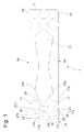
- the FIG. 1 shows a filler 1 a disc seal 3, as for example, in a pivot motor according to the DE 42 29 025 A1 is described.
- the filler 1 has a rectangular basic shape.
- the outer edge forms Contact surfaces 5; 7: 9; 11 for an elastic sealing frame 13 (see FIG. Fig. 2 ).
- the filler has at a distance at the transition region 15 of two side edges 5; 11 recesses 17; 19, whose main axes 21; 23 at point 25 intersect.
- the recesses 17; 19 extend starting from the respective contact surface 5; 11 for the sealing frame 13 inward and have a more than three-sided contour.
- the recess is determined as a pentagon or wherein two sides of the recess 17a; 17b; 19a; 19b with a clearance in the contact surface 5; 11 of the filler, so that the contact surface in a plurality of separate contact surface areas 5a; 5b; 5c; 11a; 11 b is divided.
- the recesses 17; 19 determine in the filler 1 a biasing web 27a; 27b with an open end 29, exactly in the transition 15 of two side edges 5a; 11b expires. Both recesses 17; 19 have the same distance to the transition region 15, so that the biasing web 27 has an angle of 45 ° to a contact surface.
- the open end29 has an arrow-shaped geometry.
- the filler 1 comprises a central window 31. Between the central window 31 and the recesses 17; 19 is in each case a separating web 33a; 33b, which is elastically deformable. In its longitudinal direction, the window 31 is designed waisted.
- FIG. 2 shows the complete disc seal 3.
- the filler 1 is carried out in the length and width with a certain excess to the sealing frame 13 so that this within the disc seal 3 under a bias in longitudinal and Transverse direction stands.
- the biasing webs 27a; 27b with their arrow-shaped ends 29a; 29b act exactly in the transition regions of two sealing sides 35; 37; 39 of the sealing frame 13.
- the biasing webs 27a; 27b deformed in the direction of the longitudinal axis 41 of the disk seal 3, as can be seen on the recess 19 on the short sealing side 39 of the filler 1.
- the waisted central window 31 provides over the special window shape for a uniform bias of the contact surface 5b; 9 b between the two recesses 17 on the sealing frame thirteenth
Landscapes
- Engineering & Computer Science (AREA)
- General Engineering & Computer Science (AREA)
- Mechanical Engineering (AREA)
- Physics & Mathematics (AREA)
- Fluid Mechanics (AREA)
- Specific Sealing Or Ventilating Devices For Doors And Windows (AREA)
- Seal Device For Vehicle (AREA)
- Motor Or Generator Frames (AREA)
Abstract
Description
- Die Erfindung betrifft eine Scheibendichtung gemäß dem Oberbegriff von Patentanspruch 1.
- Aus der
EP 1 150 018 A2 ist eine Scheibendichtung für einen Schwenkmotor bekannt, die aus einem Füllstück und einem außenliegenden Dichtungsrahmen besteht. Das Füllstück verfügt je nach Ausführungsform über eine Anzahl von Längs- und Querschlitzen, die dem Füllstück eine axiale und radiale Elastizität verleihen. Die Variante nachFigur 1 weist ausschließlich Längsschlitze auf, die sich nahezu über die gesamte Länge des Füllstücks erstrecken. Am Übergangsbereich zwischen einer kurzen und einer langen Dichtkante des Dichtungsrahmens liegt am Füllstück ein relativ großer Radius zum Dichtungsrahmen vor, so dass die Vorspannung in dem besagten Übergangsbereich relativ gering ist. - Bei den weiteren Ausführungsformen nach den Figuren 3 bis 5 stellt sich das Problem, dass die Füllstücke auf den Übergangsbereich des Dichtungsrahmens eine ungleichmäßige Vorspannung ausüben, zumindest, wenn man die Vorspannung der beiden Längskanten miteinander vergleicht.
- Aufgabe der vorliegenden Erfindung ist es, eine Scheibendichtung zu realisieren, deren Dichtungsrahmen eine verbesserte Vorspannung aufweist.
- Erfindungsgemäß wird die Aufgabe dadurch gelöst, dass das Füllstück in einem Abstand zu einem Übergangsbereich von zwei Seitenkanten des Dichtungsrahmens Aussparungen aufweist, deren Hauptachsen sich schneiden.
- Der große Vorteil der Erfindung besteht darin, dass insbesondere der Übergangsbereich des Dichtungsrahmens einer besonders zielgerichteten Vorspannung unterliegt.
- In weiterer vorteilhafter Ausgestaltung erweitern sich die Aussparungen ausgehend von einer Kontaktfläche zum Dichtungsrahmen nach innen. Das Ziel dieser Maßnahme besteht in der Beibehaltung einer großen Kontaktfläche zum Dichtungsrahmen.
- Gemäß einem vorteilhaften Unteranspruch bestimmen die Aussparungen im Füllstück einen Vorspannsteg mit einem offenen Ende, das in einer bevorzugten Ausführungsform eine pfeilförmige Geometrie aufweist.
- Der Abstand der Aussparungen im Füllstück ist ausgehend vom Übergangsbereich gleich, so dass die Vorspannung exakt in den Übergangsbereich wirkt.
- Die Aussparungen soll vorteilhafterweise eine mehr als dreiseitige Kontur aufweisen, wobei zwei Seiten der Aussparung mit einem Abstand in der Kontaktfläche des Füllstücks auslaufen. Dadurch wird ein größerer Bewegungsraum für den Vorspannsteg erreicht.
- In weiterer vorteilhafter Ausgestaltung weist das Füllstück ein zentrales Fenster auf.
- Ein Trennsteg zwischen einer Aussparung und dem Fenster ist elastisch verformbar. Eine Verformung des Vorspannstegs kann von dem Trennsteg wieder gegenläufig kompensiert werden, so dass die Kontaktfläche parallel verschiebbar ist.
- Im Hinblick auf eine möglichst gleichförmige Vorspannung des Füllstücks auf den Dichtungsrahmen ist das Fenster in seiner Längsrichtung tailliert ausgeführt.
- Anhand der folgenden Figurenbeschreibung soll die Erfindung näher erläutert werden.
- Es zeigt:
- Fig. 1
- Füllstück einer Scheibendichtung
- Fig. 2
- Füllstück mit montiertem Dichtungsrahmen
- Die
Figur 1 zeigt ein Füllstück 1 einer Scheibendichtung 3, wie sie beispielsweise in einem Schwenkmotor entsprechend derDE 42 29 025 A1 beschrieben ist. Das Füllstück 1 weist eine rechteckige Grundform auf. Der äußere Rand bildet Kontaktflächen 5; 7:9; 11 für einen elastischen Dichtungsrahmen 13 (s.Fig. 2 ). Als Material für das Füllstück können Kunststoffe aber auch metallische Werkstoffe dienen. Das Füllstück weist in einem Abstand am Übergangsbereich 15 zweier Seitenkanten 5; 11 Aussparungen 17; 19 auf, deren Hauptachsen 21; 23 im Punkt 25 sich schneiden. Die Aussparungen 17; 19 erweitern sich ausgehend von der jeweiligen Kontaktfläche 5; 11 für den Dichtrahmen 13 nach innen und verfügen über eine mehr als dreiseitige Kontur. In dieser konkreten Ausführung ist die Aussparung als ein Fünfeck bestimmt bzw. wobei zwei Seiten der Aussparung 17a; 17b; 19a; 19b mit einem Abstand in der Kontaktfläche 5; 11 des Füllstücks auslaufen, so dass die Kontaktfläche in mehrere getrennte Kontaktflächenbereiche 5a; 5b; 5c; 11a; 11 b unterteilt wird. Die Aussparungen 17; 19 bestimmen im Füllstück 1 einen Vorspannsteg 27a; 27b mit einem offenen Ende 29, das genau im Übergang 15 zweier Seitenkanten 5a; 11b ausläuft. Beide Aussparungen 17; 19 weisen den gleichen Abstand zum Übergangsbereich 15 auf, so dass der Vorspannsteg 27 einen Winkel von 45° zu einer Kontaktfläche aufweist. Das offene Ende29 verfügt über eine pfeilförmige Geometrie. - Des Weiteren umfasst das Füllstück 1 ein zentrales Fenster 31. Zwischen dem zentralen Fenster 31 und den Aussparungen 17; 19 besteht jeweils ein Trennsteg 33a; 33b, der elastisch verformbar ist. In seiner Längsrichtung ist das Fenster 31 tailliert ausgeführt ist.
- Die
Figur 2 zeigt die vollständige Scheibendichtung 3. Das Füllstück 1 ist in der Länge und der Breite mit einem gewissen Übermaß zum Dichtungsrahmen 13 ausgeführt, so dass dieser innerhalb der Scheibendichtung 3 unter einer Vorspannung in Längs- und Querrichtung steht. In einer zum besseren Verständnis etwas überzogenen Darstellung ist die Deformierbarkeit des Füllstücks 1 erkennbar. Die Vorspannstege 27a; 27b mit ihren pfeilförmigen Enden 29a; 29b wirken exakt in die Übergangsbereiche zweier Dichtungsseiten 35; 37; 39 des Dichtungsrahmens 13. Dabei werden die Vorspannstege 27a; 27b in Richtung der Längsachse 41 der Scheibendichtung 3 verformt, wie an der Aussparung 19 an der kurzen Dichtungsseite 39 des Füllstücks 1 erkennbar ist. Zusätzlich werden ab auch die Trennstege 33a; 33b zwischen den Aussparungen 17 und dem zentralen Fenster 31 in Richtung des Fensters verformt, so dass praktisch eine Parallelverschiebung der pfeilförmigen Enden 29a; 29b zur Längsachse 41 der Scheibendichtung 3 erfolgt und eine glattflächige Anlage des Dichtungsrahmens 13 an einer abzudichtenden Kante vorliegt. - Das taillierte zentrale Fenster 31 sorgt über die spezielle Fensterform für eine gleichmäßige Vorspannung der Kontaktfläche 5b; 9b zwischen den beiden Aussparungen 17 auf den Dichtungsrahmen 13.
Claims (9)
- Scheibendichtung (3), umfassend einen mehrseitigen Dichtungsrahmen (13), der von einem im Dichtungsrahmen (13) angeordneten Füllstück (1) in einer Ebene axial und radial vorgespannt wird, wobei das Füllstück (1) Aussparungen (17; 19; 21) aufweist, die die Elastizität des Füllstücks (1) bestimmen,
dadurch gekennzeichnet,
dass das Füllstück (1) in einem Abstand zu einem Übergangsbereich (15) von zwei Seitenkanten des Dichtungsrahmens (13) Aussparungen (17; 19) aufweist, deren Hauptachsen (21; 23) sich schneiden. - Scheibendichtung nach Anspruch 1,
dadurch gekennzeichnet,
dass sich die Aussparungen (17; 19) ausgehend von einer Kontaktfläche (5a; 5b; 5c; 11a; 11c) zum Dichtungsrahmen (13) nach innen erweitern. - Scheibendichtung nach Anspruch 2,
dadurch gekennzeichnet,
dass die Aussparungen (17; 19) im Füllstück (1) einen Vorspannsteg (27a; 27b) mit einem offenen Ende (19) bestimmen. - Scheibendichtung nach Anspruch 3,
dadurch gekennzeichnet,
dass das offene Ende (29) eine pfeilförmige Geometrie aufweist. - Scheibendichtung nach Anspruch 1,
dadurch gekennzeichnet,
dass der Abstand der Aussparungen (17; 19) im Füllstück (1) ausgehend vom Übergangsbereich (15) gleich ist. - Scheibendichtung nach Anspruch 2,
dadurch gekennzeichnet,
dass die Aussparungen (17; 19) eine mehr als dreiseitige Kontur aufweist, wobei zwei Seiten (17a; 17b; 19a; 19b) der Aussparung (17; 19) mit einem Abstand in der Kontaktfläche (5a; 5b; 11a; 11b) des Füllstücks (1) auslaufen. - Scheibendichtung nach Anspruch 1,
dadurch gekennzeichnet,
dass das Füllstück (1) ein zentrales Fenster (31) aufweist. - Scheibendichtung nach Anspruch 7,
dadurch gekennzeichnet,
dass ein Trennsteg (33a; 33b) zwischen einer Aussparung (17) und dem Fenster (31) elastisch verformbar ist. - Scheibendichtung nach Anspruch 7,
dadurch gekennzeichnet,
dass das Fenster (31) in seiner Längsrichtung tailliert ausgeführt ist.
Applications Claiming Priority (1)
| Application Number | Priority Date | Filing Date | Title |
|---|---|---|---|
| DE102008010899A DE102008010899A1 (de) | 2008-02-23 | 2008-02-23 | Scheibendichtung |
Publications (2)
| Publication Number | Publication Date |
|---|---|
| EP2093465A1 true EP2093465A1 (de) | 2009-08-26 |
| EP2093465B1 EP2093465B1 (de) | 2011-08-17 |
Family
ID=40599695
Family Applications (1)
| Application Number | Title | Priority Date | Filing Date |
|---|---|---|---|
| EP09153180A Not-in-force EP2093465B1 (de) | 2008-02-23 | 2009-02-19 | Scheibendichtung |
Country Status (3)
| Country | Link |
|---|---|
| EP (1) | EP2093465B1 (de) |
| AT (1) | ATE520909T1 (de) |
| DE (1) | DE102008010899A1 (de) |
Citations (4)
| Publication number | Priority date | Publication date | Assignee | Title |
|---|---|---|---|---|
| DE4229025A1 (de) | 1992-09-01 | 1994-03-03 | Fichtel & Sachs Ag | Schwenkmotor für einen Kraftfahrzeugstabilisator |
| EP1061266A2 (de) * | 1999-06-17 | 2000-12-20 | Bayerische Motoren Werke Aktiengesellschaft | Schwenkmotor mit Dichtungsanordnungen |
| EP1150018A2 (de) | 2000-04-29 | 2001-10-31 | Bayerische Motoren Werke Aktiengesellschaft | Dichtungselement für einen Schwenkmotor |
| EP1614905A2 (de) * | 2004-07-07 | 2006-01-11 | Zf Friedrichshafen Ag | Schwenkmotor |
Family Cites Families (1)
| Publication number | Priority date | Publication date | Assignee | Title |
|---|---|---|---|---|
| DE19918665B4 (de) * | 1999-04-24 | 2008-01-31 | Bayerische Motoren Werke Ag | Hydraulischer Schwenkmotor, insbesondere als Servomotor für Kfz |
-
2008
- 2008-02-23 DE DE102008010899A patent/DE102008010899A1/de not_active Ceased
-
2009
- 2009-02-19 EP EP09153180A patent/EP2093465B1/de not_active Not-in-force
- 2009-02-19 AT AT09153180T patent/ATE520909T1/de active
Patent Citations (4)
| Publication number | Priority date | Publication date | Assignee | Title |
|---|---|---|---|---|
| DE4229025A1 (de) | 1992-09-01 | 1994-03-03 | Fichtel & Sachs Ag | Schwenkmotor für einen Kraftfahrzeugstabilisator |
| EP1061266A2 (de) * | 1999-06-17 | 2000-12-20 | Bayerische Motoren Werke Aktiengesellschaft | Schwenkmotor mit Dichtungsanordnungen |
| EP1150018A2 (de) | 2000-04-29 | 2001-10-31 | Bayerische Motoren Werke Aktiengesellschaft | Dichtungselement für einen Schwenkmotor |
| EP1614905A2 (de) * | 2004-07-07 | 2006-01-11 | Zf Friedrichshafen Ag | Schwenkmotor |
Also Published As
| Publication number | Publication date |
|---|---|
| EP2093465B1 (de) | 2011-08-17 |
| DE102008010899A1 (de) | 2009-08-27 |
| ATE520909T1 (de) | 2011-09-15 |
Similar Documents
| Publication | Publication Date | Title |
|---|---|---|
| DE102008034922B4 (de) | Wälzlagerkäfig | |
| AT517169B1 (de) | Lageranordnung | |
| EP3581256A1 (de) | Innenraumfilter und filterelement für einen innenraumfilter | |
| DE102014115762A1 (de) | Scheibenbremse für ein Nutzfahrzeug | |
| DE102011112398A1 (de) | Förderkettenglied mit L-förmiger Bolzenausnehmung | |
| DE202013011423U1 (de) | Raupensteg für ein Pistenfahrzeug sowie Raupenkette mit Raupenstege | |
| DE102012103944A1 (de) | Laufstreifenprofil eines Fahrzeugreifens | |
| DE202014103179U1 (de) | Plattenbandelement für eine als Traktionshilfe dienende, plattenbandförmige Gleiskette für Zwillingsachsen | |
| EP3300936A1 (de) | Lager für ein bauteil eines kraftfahrzeugs | |
| DE2657906C3 (de) | Laufpolster für eine Gleiskette | |
| EP2093465B1 (de) | Scheibendichtung | |
| DE202012002697U1 (de) | Gleisbaumaschine | |
| DE102012104403A1 (de) | Laufstreifenprofil eines Fahrzeugluftreifens | |
| DE102011084750A1 (de) | Zylinderrollenlager | |
| DE102008040033A1 (de) | Baureihe eines Wischblatts | |
| DE3609779C1 (en) | Rolling element cage, in particular cross roller cage | |
| DE3306793A1 (de) | Elastisches auflager zur bauteile, maschinen, geraete od.dgl. | |
| EP3272560B1 (de) | Reifenkette mit 45°-kettenstrang | |
| DE102016124228B4 (de) | Fahrzeugsitz mit Federung | |
| EP2661566B1 (de) | Lagereinheit für nutzfahrzeuge | |
| DE102011053991A1 (de) | Wischblatt zum Reinigen von Fahrzeugscheiben | |
| DE19824445B4 (de) | Elastomerlager | |
| DE102014212715A1 (de) | Geberzylinder | |
| DE202016103916U1 (de) | Reifenkette mit 45°-Kettenstrang | |
| DE102005047452A1 (de) | Verstelleinrichtung für einen Fahrzeugsitz |
Legal Events
| Date | Code | Title | Description |
|---|---|---|---|
| PUAI | Public reference made under article 153(3) epc to a published international application that has entered the european phase |
Free format text: ORIGINAL CODE: 0009012 |
|
| AK | Designated contracting states |
Kind code of ref document: A1 Designated state(s): AT BE BG CH CY CZ DE DK EE ES FI FR GB GR HR HU IE IS IT LI LT LU LV MC MK MT NL NO PL PT RO SE SI SK TR |
|
| AX | Request for extension of the european patent |
Extension state: AL BA RS |
|
| 17P | Request for examination filed |
Effective date: 20100128 |
|
| 17Q | First examination report despatched |
Effective date: 20100222 |
|
| AKX | Designation fees paid |
Designated state(s): AT BE BG CH CY CZ DE DK EE ES FI FR GB GR HR HU IE IS IT LI LT LU LV MC MK MT NL NO PL PT RO SE SI SK TR |
|
| GRAP | Despatch of communication of intention to grant a patent |
Free format text: ORIGINAL CODE: EPIDOSNIGR1 |
|
| GRAS | Grant fee paid |
Free format text: ORIGINAL CODE: EPIDOSNIGR3 |
|
| GRAA | (expected) grant |
Free format text: ORIGINAL CODE: 0009210 |
|
| AK | Designated contracting states |
Kind code of ref document: B1 Designated state(s): AT BE BG CH CY CZ DE DK EE ES FI FR GB GR HR HU IE IS IT LI LT LU LV MC MK MT NL NO PL PT RO SE SI SK TR |
|
| REG | Reference to a national code |
Ref country code: GB Ref legal event code: FG4D Free format text: NOT ENGLISH |
|
| REG | Reference to a national code |
Ref country code: CH Ref legal event code: EP |
|
| REG | Reference to a national code |
Ref country code: IE Ref legal event code: FG4D Free format text: LANGUAGE OF EP DOCUMENT: GERMAN |
|
| REG | Reference to a national code |
Ref country code: DE Ref legal event code: R096 Ref document number: 502009001115 Country of ref document: DE Effective date: 20111020 |
|
| REG | Reference to a national code |
Ref country code: NL Ref legal event code: VDEP Effective date: 20110817 |
|
| LTIE | Lt: invalidation of european patent or patent extension |
Effective date: 20110817 |
|
| PG25 | Lapsed in a contracting state [announced via postgrant information from national office to epo] |
Ref country code: IS Free format text: LAPSE BECAUSE OF FAILURE TO SUBMIT A TRANSLATION OF THE DESCRIPTION OR TO PAY THE FEE WITHIN THE PRESCRIBED TIME-LIMIT Effective date: 20111217 Ref country code: NL Free format text: LAPSE BECAUSE OF FAILURE TO SUBMIT A TRANSLATION OF THE DESCRIPTION OR TO PAY THE FEE WITHIN THE PRESCRIBED TIME-LIMIT Effective date: 20110817 Ref country code: NO Free format text: LAPSE BECAUSE OF FAILURE TO SUBMIT A TRANSLATION OF THE DESCRIPTION OR TO PAY THE FEE WITHIN THE PRESCRIBED TIME-LIMIT Effective date: 20111117 Ref country code: PT Free format text: LAPSE BECAUSE OF FAILURE TO SUBMIT A TRANSLATION OF THE DESCRIPTION OR TO PAY THE FEE WITHIN THE PRESCRIBED TIME-LIMIT Effective date: 20111219 Ref country code: FI Free format text: LAPSE BECAUSE OF FAILURE TO SUBMIT A TRANSLATION OF THE DESCRIPTION OR TO PAY THE FEE WITHIN THE PRESCRIBED TIME-LIMIT Effective date: 20110817 Ref country code: SE Free format text: LAPSE BECAUSE OF FAILURE TO SUBMIT A TRANSLATION OF THE DESCRIPTION OR TO PAY THE FEE WITHIN THE PRESCRIBED TIME-LIMIT Effective date: 20110817 Ref country code: LT Free format text: LAPSE BECAUSE OF FAILURE TO SUBMIT A TRANSLATION OF THE DESCRIPTION OR TO PAY THE FEE WITHIN THE PRESCRIBED TIME-LIMIT Effective date: 20110817 |
|
| PG25 | Lapsed in a contracting state [announced via postgrant information from national office to epo] |
Ref country code: GR Free format text: LAPSE BECAUSE OF FAILURE TO SUBMIT A TRANSLATION OF THE DESCRIPTION OR TO PAY THE FEE WITHIN THE PRESCRIBED TIME-LIMIT Effective date: 20111118 Ref country code: CY Free format text: LAPSE BECAUSE OF FAILURE TO SUBMIT A TRANSLATION OF THE DESCRIPTION OR TO PAY THE FEE WITHIN THE PRESCRIBED TIME-LIMIT Effective date: 20110817 Ref country code: LV Free format text: LAPSE BECAUSE OF FAILURE TO SUBMIT A TRANSLATION OF THE DESCRIPTION OR TO PAY THE FEE WITHIN THE PRESCRIBED TIME-LIMIT Effective date: 20110817 Ref country code: SI Free format text: LAPSE BECAUSE OF FAILURE TO SUBMIT A TRANSLATION OF THE DESCRIPTION OR TO PAY THE FEE WITHIN THE PRESCRIBED TIME-LIMIT Effective date: 20110817 Ref country code: PL Free format text: LAPSE BECAUSE OF FAILURE TO SUBMIT A TRANSLATION OF THE DESCRIPTION OR TO PAY THE FEE WITHIN THE PRESCRIBED TIME-LIMIT Effective date: 20110817 |
|
| REG | Reference to a national code |
Ref country code: IE Ref legal event code: FD4D |
|
| PG25 | Lapsed in a contracting state [announced via postgrant information from national office to epo] |
Ref country code: IE Free format text: LAPSE BECAUSE OF FAILURE TO SUBMIT A TRANSLATION OF THE DESCRIPTION OR TO PAY THE FEE WITHIN THE PRESCRIBED TIME-LIMIT Effective date: 20110817 Ref country code: CZ Free format text: LAPSE BECAUSE OF FAILURE TO SUBMIT A TRANSLATION OF THE DESCRIPTION OR TO PAY THE FEE WITHIN THE PRESCRIBED TIME-LIMIT Effective date: 20110817 Ref country code: SK Free format text: LAPSE BECAUSE OF FAILURE TO SUBMIT A TRANSLATION OF THE DESCRIPTION OR TO PAY THE FEE WITHIN THE PRESCRIBED TIME-LIMIT Effective date: 20110817 |
|
| PG25 | Lapsed in a contracting state [announced via postgrant information from national office to epo] |
Ref country code: EE Free format text: LAPSE BECAUSE OF FAILURE TO SUBMIT A TRANSLATION OF THE DESCRIPTION OR TO PAY THE FEE WITHIN THE PRESCRIBED TIME-LIMIT Effective date: 20110817 Ref country code: IT Free format text: LAPSE BECAUSE OF FAILURE TO SUBMIT A TRANSLATION OF THE DESCRIPTION OR TO PAY THE FEE WITHIN THE PRESCRIBED TIME-LIMIT Effective date: 20110817 Ref country code: RO Free format text: LAPSE BECAUSE OF FAILURE TO SUBMIT A TRANSLATION OF THE DESCRIPTION OR TO PAY THE FEE WITHIN THE PRESCRIBED TIME-LIMIT Effective date: 20110817 |
|
| PLBE | No opposition filed within time limit |
Free format text: ORIGINAL CODE: 0009261 |
|
| STAA | Information on the status of an ep patent application or granted ep patent |
Free format text: STATUS: NO OPPOSITION FILED WITHIN TIME LIMIT |
|
| PG25 | Lapsed in a contracting state [announced via postgrant information from national office to epo] |
Ref country code: DK Free format text: LAPSE BECAUSE OF FAILURE TO SUBMIT A TRANSLATION OF THE DESCRIPTION OR TO PAY THE FEE WITHIN THE PRESCRIBED TIME-LIMIT Effective date: 20110817 |
|
| 26N | No opposition filed |
Effective date: 20120521 |
|
| BERE | Be: lapsed |
Owner name: ZF FRIEDRICHSHAFEN A.G. Effective date: 20120228 |
|
| REG | Reference to a national code |
Ref country code: DE Ref legal event code: R097 Ref document number: 502009001115 Country of ref document: DE Effective date: 20120521 |
|
| PG25 | Lapsed in a contracting state [announced via postgrant information from national office to epo] |
Ref country code: MC Free format text: LAPSE BECAUSE OF NON-PAYMENT OF DUE FEES Effective date: 20120229 |
|
| PG25 | Lapsed in a contracting state [announced via postgrant information from national office to epo] |
Ref country code: HR Free format text: LAPSE BECAUSE OF FAILURE TO SUBMIT A TRANSLATION OF THE DESCRIPTION OR TO PAY THE FEE WITHIN THE PRESCRIBED TIME-LIMIT Effective date: 20120404 |
|
| PG25 | Lapsed in a contracting state [announced via postgrant information from national office to epo] |
Ref country code: BE Free format text: LAPSE BECAUSE OF NON-PAYMENT OF DUE FEES Effective date: 20120228 |
|
| PG25 | Lapsed in a contracting state [announced via postgrant information from national office to epo] |
Ref country code: MK Free format text: LAPSE BECAUSE OF FAILURE TO SUBMIT A TRANSLATION OF THE DESCRIPTION OR TO PAY THE FEE WITHIN THE PRESCRIBED TIME-LIMIT Effective date: 20110817 |
|
| PG25 | Lapsed in a contracting state [announced via postgrant information from national office to epo] |
Ref country code: ES Free format text: LAPSE BECAUSE OF FAILURE TO SUBMIT A TRANSLATION OF THE DESCRIPTION OR TO PAY THE FEE WITHIN THE PRESCRIBED TIME-LIMIT Effective date: 20111128 |
|
| PGFP | Annual fee paid to national office [announced via postgrant information from national office to epo] |
Ref country code: FR Payment date: 20130301 Year of fee payment: 5 |
|
| PG25 | Lapsed in a contracting state [announced via postgrant information from national office to epo] |
Ref country code: BG Free format text: LAPSE BECAUSE OF FAILURE TO SUBMIT A TRANSLATION OF THE DESCRIPTION OR TO PAY THE FEE WITHIN THE PRESCRIBED TIME-LIMIT Effective date: 20111117 |
|
| PG25 | Lapsed in a contracting state [announced via postgrant information from national office to epo] |
Ref country code: MT Free format text: LAPSE BECAUSE OF FAILURE TO SUBMIT A TRANSLATION OF THE DESCRIPTION OR TO PAY THE FEE WITHIN THE PRESCRIBED TIME-LIMIT Effective date: 20110817 |
|
| REG | Reference to a national code |
Ref country code: CH Ref legal event code: PL |
|
| GBPC | Gb: european patent ceased through non-payment of renewal fee |
Effective date: 20130219 |
|
| PG25 | Lapsed in a contracting state [announced via postgrant information from national office to epo] |
Ref country code: CH Free format text: LAPSE BECAUSE OF NON-PAYMENT OF DUE FEES Effective date: 20130228 Ref country code: LI Free format text: LAPSE BECAUSE OF NON-PAYMENT OF DUE FEES Effective date: 20130228 |
|
| PG25 | Lapsed in a contracting state [announced via postgrant information from national office to epo] |
Ref country code: HR Free format text: LAPSE BECAUSE OF FAILURE TO SUBMIT A TRANSLATION OF THE DESCRIPTION OR TO PAY THE FEE WITHIN THE PRESCRIBED TIME-LIMIT Effective date: 20110817 |
|
| PG25 | Lapsed in a contracting state [announced via postgrant information from national office to epo] |
Ref country code: GB Free format text: LAPSE BECAUSE OF NON-PAYMENT OF DUE FEES Effective date: 20130219 |
|
| PG25 | Lapsed in a contracting state [announced via postgrant information from national office to epo] |
Ref country code: TR Free format text: LAPSE BECAUSE OF FAILURE TO SUBMIT A TRANSLATION OF THE DESCRIPTION OR TO PAY THE FEE WITHIN THE PRESCRIBED TIME-LIMIT Effective date: 20110817 |
|
| PG25 | Lapsed in a contracting state [announced via postgrant information from national office to epo] |
Ref country code: LU Free format text: LAPSE BECAUSE OF NON-PAYMENT OF DUE FEES Effective date: 20120219 |
|
| PG25 | Lapsed in a contracting state [announced via postgrant information from national office to epo] |
Ref country code: HU Free format text: LAPSE BECAUSE OF FAILURE TO SUBMIT A TRANSLATION OF THE DESCRIPTION OR TO PAY THE FEE WITHIN THE PRESCRIBED TIME-LIMIT Effective date: 20090219 |
|
| PGFP | Annual fee paid to national office [announced via postgrant information from national office to epo] |
Ref country code: DE Payment date: 20140417 Year of fee payment: 6 |
|
| REG | Reference to a national code |
Ref country code: FR Ref legal event code: ST Effective date: 20141031 |
|
| PG25 | Lapsed in a contracting state [announced via postgrant information from national office to epo] |
Ref country code: FR Free format text: LAPSE BECAUSE OF NON-PAYMENT OF DUE FEES Effective date: 20140228 |
|
| REG | Reference to a national code |
Ref country code: AT Ref legal event code: MM01 Ref document number: 520909 Country of ref document: AT Kind code of ref document: T Effective date: 20140219 |
|
| PG25 | Lapsed in a contracting state [announced via postgrant information from national office to epo] |
Ref country code: AT Free format text: LAPSE BECAUSE OF NON-PAYMENT OF DUE FEES Effective date: 20140219 |
|
| REG | Reference to a national code |
Ref country code: DE Ref legal event code: R119 Ref document number: 502009001115 Country of ref document: DE |
|
| PG25 | Lapsed in a contracting state [announced via postgrant information from national office to epo] |
Ref country code: DE Free format text: LAPSE BECAUSE OF NON-PAYMENT OF DUE FEES Effective date: 20150901 |