EP2093384A2 - Filtersystem für eine Außendichtung einer Turbinenschaufel - Google Patents
Filtersystem für eine Außendichtung einer Turbinenschaufel Download PDFInfo
- Publication number
- EP2093384A2 EP2093384A2 EP08253964A EP08253964A EP2093384A2 EP 2093384 A2 EP2093384 A2 EP 2093384A2 EP 08253964 A EP08253964 A EP 08253964A EP 08253964 A EP08253964 A EP 08253964A EP 2093384 A2 EP2093384 A2 EP 2093384A2
- Authority
- EP
- European Patent Office
- Prior art keywords
- filter
- component
- recited
- boas
- air seal
- Prior art date
- Legal status (The legal status is an assumption and is not a legal conclusion. Google has not performed a legal analysis and makes no representation as to the accuracy of the status listed.)
- Granted
Links
Images


Classifications
-
- F—MECHANICAL ENGINEERING; LIGHTING; HEATING; WEAPONS; BLASTING
- F01—MACHINES OR ENGINES IN GENERAL; ENGINE PLANTS IN GENERAL; STEAM ENGINES
- F01D—NON-POSITIVE DISPLACEMENT MACHINES OR ENGINES, e.g. STEAM TURBINES
- F01D11/00—Preventing or minimising internal leakage of working-fluid, e.g. between stages
- F01D11/08—Preventing or minimising internal leakage of working-fluid, e.g. between stages for sealing space between rotor blade tips and stator
-
- F—MECHANICAL ENGINEERING; LIGHTING; HEATING; WEAPONS; BLASTING
- F01—MACHINES OR ENGINES IN GENERAL; ENGINE PLANTS IN GENERAL; STEAM ENGINES
- F01D—NON-POSITIVE DISPLACEMENT MACHINES OR ENGINES, e.g. STEAM TURBINES
- F01D25/00—Component parts, details, or accessories, not provided for in, or of interest apart from, other groups
- F01D25/002—Cleaning of turbomachines
-
- F—MECHANICAL ENGINEERING; LIGHTING; HEATING; WEAPONS; BLASTING
- F01—MACHINES OR ENGINES IN GENERAL; ENGINE PLANTS IN GENERAL; STEAM ENGINES
- F01D—NON-POSITIVE DISPLACEMENT MACHINES OR ENGINES, e.g. STEAM TURBINES
- F01D25/00—Component parts, details, or accessories, not provided for in, or of interest apart from, other groups
- F01D25/08—Cooling; Heating; Heat-insulation
- F01D25/12—Cooling
-
- F—MECHANICAL ENGINEERING; LIGHTING; HEATING; WEAPONS; BLASTING
- F01—MACHINES OR ENGINES IN GENERAL; ENGINE PLANTS IN GENERAL; STEAM ENGINES
- F01D—NON-POSITIVE DISPLACEMENT MACHINES OR ENGINES, e.g. STEAM TURBINES
- F01D5/00—Blades; Blade-carrying members; Heating, heat-insulating, cooling or antivibration means on the blades or the members
- F01D5/12—Blades
- F01D5/14—Form or construction
- F01D5/18—Hollow blades, i.e. blades with cooling or heating channels or cavities; Heating, heat-insulating or cooling means on blades
- F01D5/187—Convection cooling
-
- F—MECHANICAL ENGINEERING; LIGHTING; HEATING; WEAPONS; BLASTING
- F05—INDEXING SCHEMES RELATING TO ENGINES OR PUMPS IN VARIOUS SUBCLASSES OF CLASSES F01-F04
- F05D—INDEXING SCHEME FOR ASPECTS RELATING TO NON-POSITIVE-DISPLACEMENT MACHINES OR ENGINES, GAS-TURBINES OR JET-PROPULSION PLANTS
- F05D2260/00—Function
- F05D2260/20—Heat transfer, e.g. cooling
- F05D2260/201—Heat transfer, e.g. cooling by impingement of a fluid
-
- F—MECHANICAL ENGINEERING; LIGHTING; HEATING; WEAPONS; BLASTING
- F05—INDEXING SCHEMES RELATING TO ENGINES OR PUMPS IN VARIOUS SUBCLASSES OF CLASSES F01-F04
- F05D—INDEXING SCHEME FOR ASPECTS RELATING TO NON-POSITIVE-DISPLACEMENT MACHINES OR ENGINES, GAS-TURBINES OR JET-PROPULSION PLANTS
- F05D2260/00—Function
- F05D2260/60—Fluid transfer
- F05D2260/607—Preventing clogging or obstruction of flow paths by dirt, dust, or foreign particles
-
- Y—GENERAL TAGGING OF NEW TECHNOLOGICAL DEVELOPMENTS; GENERAL TAGGING OF CROSS-SECTIONAL TECHNOLOGIES SPANNING OVER SEVERAL SECTIONS OF THE IPC; TECHNICAL SUBJECTS COVERED BY FORMER USPC CROSS-REFERENCE ART COLLECTIONS [XRACs] AND DIGESTS
- Y02—TECHNOLOGIES OR APPLICATIONS FOR MITIGATION OR ADAPTATION AGAINST CLIMATE CHANGE
- Y02T—CLIMATE CHANGE MITIGATION TECHNOLOGIES RELATED TO TRANSPORTATION
- Y02T50/00—Aeronautics or air transport
- Y02T50/60—Efficient propulsion technologies, e.g. for aircraft
Definitions
- the present invention relates to a gas turbine engine and more particularly to a vane and blade outer air seal (BOAS).
- BOAS vane and blade outer air seal
- Gas turbine engines generally include fan, compressor, combustor and turbine sections positioned along an axial centerline often referred to as the engine axis of rotation.
- the fan, compressor, and turbine sections each include a series of stator and rotor blade assemblies.
- An array of blades and an axially adjacent array of vanes are referred to as a stage.
- Each stator assembly which does not rotate (but may have variable pitch vanes), increases the efficiency of the engine by guiding core gas flow into or out of the rotor assemblies.
- Each rotor blade assembly includes a multiple of blades extending outwardly from the circumference of a disk. Platforms extend laterally outward from each blade and collectively form an inner radial flowpath boundary for core gas passing through the rotor assembly.
- An outer case including a multiple of blade outer air seals (BOAS), provides an outer radial flow path boundary.
- a multiple of BOAS are typically provided to accommodate thermal and dynamic variation typical in a high pressure turbine (HPT) section of the gas turbine engine.
- the BOAS are subjected to relatively high temperatures and receive a secondary cooling airflow for temperature control.
- the secondary cooling airflow is communicated into the BOAS then through annular cooling channels within the BOAS.
- the annular cooling channels have been reduced in size and increased in numbers so as to increase the secondary cooling airflow efficiency.
- these relatively small internal passageways may become plugged with particulate in the secondary cooling airflow.
- Conventional HPT BOAS particulate plugging mitigation is either nonexistent or is manifested as particulate entrapment features in the secondary flow system a system upstream of the BOAS. Either technique may be less than effective with these relatively small internal passageways.
- a gas turbine engine component includes a blade outer air seal having an impingement cavity; and a filter mounted adjacent the impingement cavity.
- a method of filtering a secondary cooling airflow within a gas turbine engine includes filtering particles out of a secondary cooling airflow outboard of a cooling channel in communication with the secondary cooling airflow.
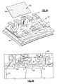
- FIG. 1 schematically illustrates a gas turbine engine 10 (illustrated partially here as a High Pressure Turbine HPT section) having a turbine 12 disposed along a common engine longitudinal axis 14.
- the illustrated embodiment provides an air seal for high pressure turbine (HPT) blade outer air seal (BOAS) assemblies, also often known as turbine shroud assemblies.
- HPT high pressure turbine
- BOAS blade outer air seal
- the BOAS may find beneficial use in many industries including aerospace, industrial, electricity generation, naval propulsion, pumping sets for gas and oil transmission, aircraft propulsion, vehicle engines, and stationary power plants.
- the engine 10 includes a BOAS assembly 16 for sealing within the turbine 12.
- the turbine 12 includes a rotor assembly 18 disposed between forward 20 and aft 22 stationary vane assemblies.
- Each vane assembly 20, 22 includes a plurality of vanes 24 circumferentially disposed around an inner vane support 26.
- the vanes 24 of each assembly 20, 22 extend between the inner vane support 26F, 26A and an outer vane support 28F, 28A.
- the outer vane supports 28F, 28A are attached to an engine case 32.
- the rotor assembly 18 includes a plurality of blades 34 circumferentially disposed around a disk 36, each blade 34 including a root 38 and an airfoil 40.
- the disk 36 includes a hub 42 and a rim 44, and a web 46 extending therebetween.
- the roots 38 are received within the rim 44 of the disk 36 and the airfoils 40 extend radially outward.
- the outer edge of each airfoil 40 may be referred to as the blade tip 48.
- the BOAS assembly 16 is disposed in an annulus radially between the engine case 32 and the blade tips 48 of the rotor assembly 18, and axially between the forward 28F and aft 28A outer vane supports. Locating the BOAS assembly 16 between the forward 28F and aft 28A outer vane supports minimizes or eliminates loading on the BOAS assembly 16 from either vane assembly 20, 22.
- the BOAS assembly 16 includes a blade outer air seal (BOAS) support 50 and a multiple of blade outer air seals (BOAS) 54 mountable thereto ( Figure 2B ). It should be understood that the BOAS support 50 may be a hoop or manufactured from individual segments.
- the BOAS support 50 is fixed within the engine case 32 by a press fit between an outer radial BOAS surface 56 and the engine case 32.
- a support attachment flange 58 further secures the BOAS support 50 with a receipt slot 60 within the engine case 32.
- the BOAS support 50 includes a multiple of forward flanges 62 and aft flanges 64 which extend from an inner radial surface 65 thereof.
- the flanges 62, 64 are shaped such that they form a sideways "U" shaped slot 66, 68 with the opening thereof facing generally aft to receive the BOAS 54 in a generally upward and forward direction ( Figure 2B ).
- the BOAS 54 includes a body 70 which defines a forward flange 72 and an aft flange 74.
- the forward flange 72 and the aft flange 74 respectively engage the slots 66, 68 in the BOAS support 50 ( Figure 2B ).
- the forward flange 72 and the aft flange 74 are assembled radially outward and forward to engage the slots 66, 68 and secure each individual BOAS 54 thereto.
- the forward flanges 62 and aft flanges 64 are circumferentially segmented to receive the BOAS 54 in a circumferentially rotated locking arrangement as generally understood.
- a relatively small intervening gap between each adjacent BOAS 54 facilitates thermal and dynamic relative movement.
- a featherseal 76 is typically engaged between each two adjacent BOAS 54 to close the gap and thereby minimize leakage therebetween to increase the engine operating efficiency.
- the BOAS 54 includes an impingement cavity 80 generally between the forward flange 72 and the aft flange 74.
- the impingement cavity 80 includes an inlet area 82 having a multiple of inlets 82A which communicate with a multitude of annular cooling channels 84 to receive a secondary cooling airflow.
- the multitude of annular cooling channels 84 may be formed through an investment casting process.
- a filter 86 is located within the impingement cavity 80 over the multitude of inlets 82A ( Figure 3A ) to filter particulate-laden secondary cooling airflow immediately prior to being received within the multitude of annular cooling channels 84.
- the filter 86 may be situated just radially outboard of the inlet area 82 within the BOAS impingement cavity 80.
- the filter 86 in one non-limiting embodiment, may be manufactured of a finely perforated plate of a typical turbine case Nickel alloy such as INCONEL 625, where the perforated area is significantly larger than the BOAS cooling channel inlet area 82, so as to not meter the secondary cooling airflow and be relatively tolerant to particulate buildup in the filter 86.
- the filter 86 may be welded, or mechanically attached via a slot fitting 88 ( Figure 4 ).
- the filter 86 is amenable to inspection and replacement at standard service intervals.
- the placement of the apertures 86A in the filter 86 may be placed strategically to discourage the passage of particles through the filter 86 by orientation of the apertures 86A away from the momentum of relatively larger particles that depart from the secondary cooling airflow in the OD BOAS secondary flow cavity ( Figure 5 ). That is, the filter apertures 86A may be non-perpendicular to the filter 86.
- the filter apertures 86A may thereby be oriented to offset incoming particle trajectory.
- the filter 86' includes a particle entrapment feature 90 to collect particulates along an edge 92 of the filter 86'
- the particle entrapment feature 90 in one non-limiting embodiment may include segments 94 which extend transverse to a plane 96 defined by a filter plate 98 of the filter 86' to collect particulate in areas known through field experience.
- the segments 84 may be folded segments.
Landscapes
- Engineering & Computer Science (AREA)
- Mechanical Engineering (AREA)
- General Engineering & Computer Science (AREA)
- Turbine Rotor Nozzle Sealing (AREA)
Applications Claiming Priority (1)
| Application Number | Priority Date | Filing Date | Title |
|---|---|---|---|
| US12/036,267 US8439639B2 (en) | 2008-02-24 | 2008-02-24 | Filter system for blade outer air seal |
Publications (4)
| Publication Number | Publication Date |
|---|---|
| EP2093384A2 true EP2093384A2 (de) | 2009-08-26 |
| EP2093384A3 EP2093384A3 (de) | 2012-05-30 |
| EP2093384B1 EP2093384B1 (de) | 2015-04-29 |
| EP2093384B2 EP2093384B2 (de) | 2019-06-12 |
Family
ID=40756279
Family Applications (1)
| Application Number | Title | Priority Date | Filing Date |
|---|---|---|---|
| EP08253964.4A Active EP2093384B2 (de) | 2008-02-24 | 2008-12-11 | Filtersystem für eine Außendichtung einer Turbinenschaufel |
Country Status (2)
| Country | Link |
|---|---|
| US (1) | US8439639B2 (de) |
| EP (1) | EP2093384B2 (de) |
Cited By (7)
| Publication number | Priority date | Publication date | Assignee | Title |
|---|---|---|---|---|
| WO2011115880A1 (en) * | 2010-03-18 | 2011-09-22 | General Electric Company | Turbine shroud hanger with debris filter |
| WO2015031764A1 (en) * | 2013-08-29 | 2015-03-05 | United Technologies Corporation | Blade outer air seal made of ceramic matrix composite |
| EP3428411A1 (de) * | 2017-06-20 | 2019-01-16 | United Technologies Corporation | Gasturbinentriebwerk, kühlverfahren und schmutzpartikelsieb |
| US10364706B2 (en) | 2013-12-17 | 2019-07-30 | United Technologies Corporation | Meter plate for blade outer air seal |
| US10577963B2 (en) | 2014-01-20 | 2020-03-03 | United Technologies Corporation | Retention clip for a blade outer air seal |
| WO2021001615A1 (fr) * | 2019-07-04 | 2021-01-07 | Safran Aircraft Engines | Dispositif de refroidissement ameliore d'anneau de turbine d'aeronef |
| EP2890878B1 (de) * | 2012-08-29 | 2021-07-14 | Raytheon Technologies Corporation | Aussenluftdichtung für eine turbinenschaufel |
Families Citing this family (33)
| Publication number | Priority date | Publication date | Assignee | Title |
|---|---|---|---|---|
| US10286407B2 (en) | 2007-11-29 | 2019-05-14 | General Electric Company | Inertial separator |
| US8439639B2 (en) * | 2008-02-24 | 2013-05-14 | United Technologies Corporation | Filter system for blade outer air seal |
| US8740551B2 (en) * | 2009-08-18 | 2014-06-03 | Pratt & Whitney Canada Corp. | Blade outer air seal cooling |
| US8596963B1 (en) * | 2011-07-07 | 2013-12-03 | Florida Turbine Technologies, Inc. | BOAS for a turbine |
| US9133724B2 (en) * | 2012-01-09 | 2015-09-15 | General Electric Company | Turbomachine component including a cover plate |
| US9506367B2 (en) | 2012-07-20 | 2016-11-29 | United Technologies Corporation | Blade outer air seal having inward pointing extension |
| US9617866B2 (en) | 2012-07-27 | 2017-04-11 | United Technologies Corporation | Blade outer air seal for a gas turbine engine |
| US9115596B2 (en) | 2012-08-07 | 2015-08-25 | United Technologies Corporation | Blade outer air seal having anti-rotation feature |
| US9803491B2 (en) | 2012-12-31 | 2017-10-31 | United Technologies Corporation | Blade outer air seal having shiplap structure |
| WO2015021029A1 (en) | 2013-08-06 | 2015-02-12 | United Technologies Corporation | Boas with radial load feature |
| WO2015034697A1 (en) * | 2013-09-06 | 2015-03-12 | United Technologies Corporation | Canted boas intersegment geometry |
| CA2949539A1 (en) | 2014-05-29 | 2016-02-18 | General Electric Company | Engine components with impingement cooling features |
| US10422235B2 (en) | 2014-05-29 | 2019-09-24 | General Electric Company | Angled impingement inserts with cooling features |
| US9915176B2 (en) | 2014-05-29 | 2018-03-13 | General Electric Company | Shroud assembly for turbine engine |
| US9957816B2 (en) | 2014-05-29 | 2018-05-01 | General Electric Company | Angled impingement insert |
| WO2016025056A2 (en) | 2014-05-29 | 2016-02-18 | General Electric Company | Turbine engine and particle separators therefore |
| WO2016032585A2 (en) | 2014-05-29 | 2016-03-03 | General Electric Company | Turbine engine, components, and methods of cooling same |
| US11033845B2 (en) | 2014-05-29 | 2021-06-15 | General Electric Company | Turbine engine and particle separators therefore |
| US10036319B2 (en) | 2014-10-31 | 2018-07-31 | General Electric Company | Separator assembly for a gas turbine engine |
| US10167725B2 (en) | 2014-10-31 | 2019-01-01 | General Electric Company | Engine component for a turbine engine |
| US20160123186A1 (en) * | 2014-10-31 | 2016-05-05 | General Electric Company | Shroud assembly for a turbine engine |
| US10215099B2 (en) * | 2015-02-06 | 2019-02-26 | United Technologies Corporation | System and method for limiting movement of a retainer ring of a gas turbine engine |
| US9988936B2 (en) | 2015-10-15 | 2018-06-05 | General Electric Company | Shroud assembly for a gas turbine engine |
| US10174620B2 (en) | 2015-10-15 | 2019-01-08 | General Electric Company | Turbine blade |
| US10428664B2 (en) | 2015-10-15 | 2019-10-01 | General Electric Company | Nozzle for a gas turbine engine |
| US10329941B2 (en) | 2016-05-06 | 2019-06-25 | United Technologies Corporation | Impingement manifold |
| US10704425B2 (en) | 2016-07-14 | 2020-07-07 | General Electric Company | Assembly for a gas turbine engine |
| US10584636B2 (en) | 2017-01-27 | 2020-03-10 | Mitsubishi Hitachi Power Systems Americas, Inc. | Debris filter apparatus for preventing clogging of turbine vane cooling holes |
| US10626751B2 (en) * | 2017-05-30 | 2020-04-21 | United Technologies Corporation | Turbine cooling air metering arrangement |
| US11111806B2 (en) * | 2018-08-06 | 2021-09-07 | Raytheon Technologies Corporation | Blade outer air seal with circumferential hook assembly |
| US11035248B1 (en) | 2019-11-25 | 2021-06-15 | General Electric Company | Unitary body turbine shrouds including shot peen screens integrally formed therein and turbine systems thereof |
| US11619137B1 (en) * | 2021-12-30 | 2023-04-04 | Rolls-Royce Corporation | CMAS traps for gas turbine engines |
| US12404218B2 (en) | 2021-12-30 | 2025-09-02 | Rolls-Royce Corporation | Article with surface structures for CMAS resistance |
Family Cites Families (37)
| Publication number | Priority date | Publication date | Assignee | Title |
|---|---|---|---|---|
| US3148043A (en) † | 1962-03-29 | 1964-09-08 | Boeing Co | Moisture and particle removing means for engines |
| US3825364A (en) † | 1972-06-09 | 1974-07-23 | Gen Electric | Porous abradable turbine shroud |
| US4303371A (en) * | 1978-06-05 | 1981-12-01 | General Electric Company | Shroud support with impingement baffle |
| US4551064A (en) * | 1982-03-05 | 1985-11-05 | Rolls-Royce Limited | Turbine shroud and turbine shroud assembly |
| US5092735A (en) * | 1990-07-02 | 1992-03-03 | The United States Of America As Represented By The Secretary Of The Air Force | Blade outer air seal cooling system |
| US5169287A (en) † | 1991-05-20 | 1992-12-08 | General Electric Company | Shroud cooling assembly for gas turbine engine |
| US5480281A (en) * | 1994-06-30 | 1996-01-02 | General Electric Co. | Impingement cooling apparatus for turbine shrouds having ducts of increasing cross-sectional area in the direction of post-impingement cooling flow |
| US5639210A (en) * | 1995-10-23 | 1997-06-17 | United Technologies Corporation | Rotor blade outer tip seal apparatus |
| US5791871A (en) * | 1996-12-18 | 1998-08-11 | United Technologies Corporation | Turbine engine rotor assembly blade outer air seal |
| FR2766517B1 (fr) * | 1997-07-24 | 1999-09-03 | Snecma | Dispositif de ventilation d'un anneau de turbomachine |
| JP3462732B2 (ja) * | 1997-10-21 | 2003-11-05 | 三菱重工業株式会社 | ガスタービン静翼のダブルクロスシール装置 |
| US6146091A (en) † | 1998-03-03 | 2000-11-14 | Mitsubishi Heavy Industries, Ltd. | Gas turbine cooling structure |
| US6139257A (en) * | 1998-03-23 | 2000-10-31 | General Electric Company | Shroud cooling assembly for gas turbine engine |
| US6126389A (en) * | 1998-09-02 | 2000-10-03 | General Electric Co. | Impingement cooling for the shroud of a gas turbine |
| US6179560B1 (en) * | 1998-12-16 | 2001-01-30 | United Technologies Corporation | Turbomachinery module with improved maintainability |
| WO2001066914A1 (en) * | 2000-03-07 | 2001-09-13 | Mitsubishi Heavy Industries, Ltd. | Gas turbine split ring |
| US6431825B1 (en) * | 2000-07-28 | 2002-08-13 | Alstom (Switzerland) Ltd | Seal between static turbine parts |
| FR2829176B1 (fr) * | 2001-08-30 | 2005-06-24 | Snecma Moteurs | Carter de stator de turbomachine |
| FR2832178B1 (fr) † | 2001-11-15 | 2004-07-09 | Snecma Moteurs | Dispositif de refroidissement pour anneaux de turbine a gaz |
| US6612809B2 (en) * | 2001-11-28 | 2003-09-02 | General Electric Company | Thermally compliant discourager seal |
| US6722850B2 (en) * | 2002-07-22 | 2004-04-20 | General Electric Company | Endface gap sealing of steam turbine packing seal segments and retrofitting thereof |
| US7033138B2 (en) * | 2002-09-06 | 2006-04-25 | Mitsubishi Heavy Industries, Ltd. | Ring segment of gas turbine |
| US6733234B2 (en) * | 2002-09-13 | 2004-05-11 | Siemens Westinghouse Power Corporation | Biased wear resistant turbine seal assembly |
| US6883807B2 (en) * | 2002-09-13 | 2005-04-26 | Seimens Westinghouse Power Corporation | Multidirectional turbine shim seal |
| US7147432B2 (en) | 2003-11-24 | 2006-12-12 | General Electric Company | Turbine shroud asymmetrical cooling elements |
| US6997673B2 (en) * | 2003-12-11 | 2006-02-14 | Honeywell International, Inc. | Gas turbine high temperature turbine blade outer air seal assembly |
| US7063503B2 (en) * | 2004-04-15 | 2006-06-20 | Pratt & Whitney Canada Corp. | Turbine shroud cooling system |
| US20070048122A1 (en) † | 2005-08-30 | 2007-03-01 | United Technologies Corporation | Debris-filtering technique for gas turbine engine component air cooling system |
| US7607885B2 (en) | 2006-07-31 | 2009-10-27 | General Electric Company | Methods and apparatus for operating gas turbine engines |
| US7553128B2 (en) * | 2006-10-12 | 2009-06-30 | United Technologies Corporation | Blade outer air seals |
| US7670108B2 (en) * | 2006-11-21 | 2010-03-02 | Siemens Energy, Inc. | Air seal unit adapted to be positioned adjacent blade structure in a gas turbine |
| US7597533B1 (en) * | 2007-01-26 | 2009-10-06 | Florida Turbine Technologies, Inc. | BOAS with multi-metering diffusion cooling |
| US7665962B1 (en) * | 2007-01-26 | 2010-02-23 | Florida Turbine Technologies, Inc. | Segmented ring for an industrial gas turbine |
| US8123466B2 (en) * | 2007-03-01 | 2012-02-28 | United Technologies Corporation | Blade outer air seal |
| US8439629B2 (en) * | 2007-03-01 | 2013-05-14 | United Technologies Corporation | Blade outer air seal |
| US7704039B1 (en) * | 2007-03-21 | 2010-04-27 | Florida Turbine Technologies, Inc. | BOAS with multiple trenched film cooling slots |
| US8439639B2 (en) * | 2008-02-24 | 2013-05-14 | United Technologies Corporation | Filter system for blade outer air seal |
-
2008
- 2008-02-24 US US12/036,267 patent/US8439639B2/en active Active
- 2008-12-11 EP EP08253964.4A patent/EP2093384B2/de active Active
Cited By (12)
| Publication number | Priority date | Publication date | Assignee | Title |
|---|---|---|---|---|
| WO2011115880A1 (en) * | 2010-03-18 | 2011-09-22 | General Electric Company | Turbine shroud hanger with debris filter |
| EP2890878B1 (de) * | 2012-08-29 | 2021-07-14 | Raytheon Technologies Corporation | Aussenluftdichtung für eine turbinenschaufel |
| WO2015031764A1 (en) * | 2013-08-29 | 2015-03-05 | United Technologies Corporation | Blade outer air seal made of ceramic matrix composite |
| US10077670B2 (en) | 2013-08-29 | 2018-09-18 | United Technologies Corporation | Blade outer air seal made of ceramic matrix composite |
| US10364706B2 (en) | 2013-12-17 | 2019-07-30 | United Technologies Corporation | Meter plate for blade outer air seal |
| US10577963B2 (en) | 2014-01-20 | 2020-03-03 | United Technologies Corporation | Retention clip for a blade outer air seal |
| US11118468B2 (en) | 2014-01-20 | 2021-09-14 | Raytheon Technologies Corporation | Retention clip for a blade outer air seal |
| EP3428411A1 (de) * | 2017-06-20 | 2019-01-16 | United Technologies Corporation | Gasturbinentriebwerk, kühlverfahren und schmutzpartikelsieb |
| US10427075B2 (en) | 2017-06-20 | 2019-10-01 | United Technologies Corporation | Debris strainer for gas turbine engine cooling flow |
| WO2021001615A1 (fr) * | 2019-07-04 | 2021-01-07 | Safran Aircraft Engines | Dispositif de refroidissement ameliore d'anneau de turbine d'aeronef |
| FR3098238A1 (fr) * | 2019-07-04 | 2021-01-08 | Safran Aircraft Engines | dispositif de refroidissement amélioré d’anneau de turbine d’aéronef |
| US11795838B2 (en) | 2019-07-04 | 2023-10-24 | Safran Aircraft Engines | Aircraft turbine shroud cooling device |
Also Published As
| Publication number | Publication date |
|---|---|
| EP2093384B1 (de) | 2015-04-29 |
| EP2093384A3 (de) | 2012-05-30 |
| US8439639B2 (en) | 2013-05-14 |
| US20090214329A1 (en) | 2009-08-27 |
| EP2093384B2 (de) | 2019-06-12 |
Similar Documents
| Publication | Publication Date | Title |
|---|---|---|
| EP2093384B1 (de) | Filtersystem für eine Außendichtung einer Turbinenschaufel | |
| EP1965031B1 (de) | Mantelringdichtung | |
| EP2562365B1 (de) | Außenschaufelluftdichtung mit mehrfacher Aufprallplattenanordnung | |
| US8277177B2 (en) | Fluidic rim seal system for turbine engines | |
| US7094029B2 (en) | Methods and apparatus for controlling gas turbine engine rotor tip clearances | |
| EP1079074B1 (de) | Leitschaufel und Stator für eine Turbomaschine | |
| EP2055898B1 (de) | Gasturbinentriebwerk mit in Umfangsrichtung angeordneten Schaufeln mit Plattformkühlung | |
| EP2365235B1 (de) | Gekühlte Turbinenkantendichtung | |
| US10760423B2 (en) | Spoked rotor for a gas turbine engine | |
| US10287895B2 (en) | Midspan shrouded turbine rotor blades | |
| EP3150803B1 (de) | Schaufelprofil und kühlverfahren | |
| US9790792B2 (en) | Asymmetrically slotted rotor for a gas turbine engine | |
| EP2844839A1 (de) | Turbinenschaufel mit lokaler wanddickensteuerung | |
| US20180347466A1 (en) | Engine component with insert | |
| WO2014025571A1 (en) | Rotating turbine component with preferential hole alignment | |
| EP3557001B1 (de) | Kühlanordnung für motorkomponenten | |
| EP2551468B1 (de) | Anordnung einer Schaufelspitzendichtung mit durchgangsverbundenen Hohlräumen und zugehöriges Betriebsverfahren | |
| EP2586971B1 (de) | Abstandhalter, Rotor, Welle und Verfahren zur Orientierung des Kraftflusses während des Zusammenbaus des Rotors | |
| EP2715144B1 (de) | Leicht anpassbare verdichterzapfluft-vorrichtung stromab einer leitschaufelplattform | |
| EP2530244B1 (de) | Ein Stator umliegend eines Rotors und Verfahren zur Kühlung | |
| US10738638B2 (en) | Rotor blade with wheel space swirlers and method for forming a rotor blade with wheel space swirlers | |
| CN120608740A (zh) | 带有具有一组冷却导管的叶片组件的涡轮发动机 |
Legal Events
| Date | Code | Title | Description |
|---|---|---|---|
| PUAI | Public reference made under article 153(3) epc to a published international application that has entered the european phase |
Free format text: ORIGINAL CODE: 0009012 |
|
| AK | Designated contracting states |
Kind code of ref document: A2 Designated state(s): AT BE BG CH CY CZ DE DK EE ES FI FR GB GR HR HU IE IS IT LI LT LU LV MC MT NL NO PL PT RO SE SI SK TR |
|
| AX | Request for extension of the european patent |
Extension state: AL BA MK RS |
|
| PUAL | Search report despatched |
Free format text: ORIGINAL CODE: 0009013 |
|
| AK | Designated contracting states |
Kind code of ref document: A3 Designated state(s): AT BE BG CH CY CZ DE DK EE ES FI FR GB GR HR HU IE IS IT LI LT LU LV MC MT NL NO PL PT RO SE SI SK TR |
|
| AX | Request for extension of the european patent |
Extension state: AL BA MK RS |
|
| RIC1 | Information provided on ipc code assigned before grant |
Ipc: F01D 25/12 20060101ALI20120424BHEP Ipc: F01D 11/08 20060101AFI20120424BHEP Ipc: F01D 5/18 20060101ALI20120424BHEP Ipc: F01D 25/00 20060101ALI20120424BHEP |
|
| 17P | Request for examination filed |
Effective date: 20121128 |
|
| AKX | Designation fees paid |
Designated state(s): DE GB |
|
| 17Q | First examination report despatched |
Effective date: 20130315 |
|
| GRAP | Despatch of communication of intention to grant a patent |
Free format text: ORIGINAL CODE: EPIDOSNIGR1 |
|
| INTG | Intention to grant announced |
Effective date: 20141215 |
|
| GRAS | Grant fee paid |
Free format text: ORIGINAL CODE: EPIDOSNIGR3 |
|
| GRAA | (expected) grant |
Free format text: ORIGINAL CODE: 0009210 |
|
| AK | Designated contracting states |
Kind code of ref document: B1 Designated state(s): DE GB |
|
| REG | Reference to a national code |
Ref country code: GB Ref legal event code: FG4D |
|
| REG | Reference to a national code |
Ref country code: DE Ref legal event code: R096 Ref document number: 602008037905 Country of ref document: DE Effective date: 20150611 |
|
| REG | Reference to a national code |
Ref country code: DE Ref legal event code: R026 Ref document number: 602008037905 Country of ref document: DE |
|
| PLBI | Opposition filed |
Free format text: ORIGINAL CODE: 0009260 |
|
| PLAX | Notice of opposition and request to file observation + time limit sent |
Free format text: ORIGINAL CODE: EPIDOSNOBS2 |
|
| 26 | Opposition filed |
Opponent name: SNECMA Effective date: 20160128 |
|
| PLAF | Information modified related to communication of a notice of opposition and request to file observations + time limit |
Free format text: ORIGINAL CODE: EPIDOSCOBS2 |
|
| PLBB | Reply of patent proprietor to notice(s) of opposition received |
Free format text: ORIGINAL CODE: EPIDOSNOBS3 |
|
| PLAB | Opposition data, opponent's data or that of the opponent's representative modified |
Free format text: ORIGINAL CODE: 0009299OPPO |
|
| RAP2 | Party data changed (patent owner data changed or rights of a patent transferred) |
Owner name: UNITED TECHNOLOGIES CORPORATION |
|
| R26 | Opposition filed (corrected) |
Opponent name: SAFRAN AIRCRAFT ENGINES Effective date: 20160128 |
|
| REG | Reference to a national code |
Ref country code: DE Ref legal event code: R082 Ref document number: 602008037905 Country of ref document: DE Representative=s name: SCHMITT-NILSON SCHRAUD WAIBEL WOHLFROM PATENTA, DE |
|
| REG | Reference to a national code |
Ref country code: DE Ref legal event code: R082 Ref document number: 602008037905 Country of ref document: DE Representative=s name: SCHMITT-NILSON SCHRAUD WAIBEL WOHLFROM PATENTA, DE Ref country code: DE Ref legal event code: R081 Ref document number: 602008037905 Country of ref document: DE Owner name: UNITED TECHNOLOGIES CORP. (N.D.GES.D. STAATES , US Free format text: FORMER OWNER: UNITED TECHNOLOGIES CORPORATION, HARTFORD, CONN., US Ref country code: DE Ref legal event code: R081 Ref document number: 602008037905 Country of ref document: DE Owner name: UNITED TECHNOLOGIES CORP. (N.D.GES.D. STAATES , US Free format text: FORMER OWNER: UNITED TECHNOLOGIES CORP. (N.D.GES.D. STAATES DELAWARE), FARMINGTON, CONN., US |
|
| APBM | Appeal reference recorded |
Free format text: ORIGINAL CODE: EPIDOSNREFNO |
|
| APBP | Date of receipt of notice of appeal recorded |
Free format text: ORIGINAL CODE: EPIDOSNNOA2O |
|
| APAH | Appeal reference modified |
Free format text: ORIGINAL CODE: EPIDOSCREFNO |
|
| APBU | Appeal procedure closed |
Free format text: ORIGINAL CODE: EPIDOSNNOA9O |
|
| PUAH | Patent maintained in amended form |
Free format text: ORIGINAL CODE: 0009272 |
|
| STAA | Information on the status of an ep patent application or granted ep patent |
Free format text: STATUS: PATENT MAINTAINED AS AMENDED |
|
| 27A | Patent maintained in amended form |
Effective date: 20190612 |
|
| AK | Designated contracting states |
Kind code of ref document: B2 Designated state(s): DE GB |
|
| REG | Reference to a national code |
Ref country code: DE Ref legal event code: R102 Ref document number: 602008037905 Country of ref document: DE |
|
| REG | Reference to a national code |
Ref country code: DE Ref legal event code: R081 Ref document number: 602008037905 Country of ref document: DE Owner name: RAYTHEON TECHNOLOGIES CORPORATION (N.D.GES.D.S, US Free format text: FORMER OWNER: UNITED TECHNOLOGIES CORP. (N.D.GES.D. STAATES DELAWARE), FARMINGTON, CONN., US Ref country code: DE Ref legal event code: R081 Ref document number: 602008037905 Country of ref document: DE Owner name: RTX CORPORATION (N.D.GES.D. STAATES DELAWARE),, US Free format text: FORMER OWNER: UNITED TECHNOLOGIES CORP. (N.D.GES.D. STAATES DELAWARE), FARMINGTON, CONN., US |
|
| P01 | Opt-out of the competence of the unified patent court (upc) registered |
Effective date: 20230519 |
|
| REG | Reference to a national code |
Ref country code: DE Ref legal event code: R081 Ref document number: 602008037905 Country of ref document: DE Owner name: RTX CORPORATION (N.D.GES.D. STAATES DELAWARE),, US Free format text: FORMER OWNER: RAYTHEON TECHNOLOGIES CORPORATION (N.D.GES.D.STAATES DELAWARE), ARLINGTON, VA, US |
|
| PGFP | Annual fee paid to national office [announced via postgrant information from national office to epo] |
Ref country code: DE Payment date: 20251126 Year of fee payment: 18 |
|
| PGFP | Annual fee paid to national office [announced via postgrant information from national office to epo] |
Ref country code: GB Payment date: 20251119 Year of fee payment: 18 |