EP2093382A2 - Statorschaufel mit aufgefächerter Kühlungslochanordnung auf einem breiten Übergang zwischen Profil und Plattform - Google Patents
Statorschaufel mit aufgefächerter Kühlungslochanordnung auf einem breiten Übergang zwischen Profil und Plattform Download PDFInfo
- Publication number
- EP2093382A2 EP2093382A2 EP08253944A EP08253944A EP2093382A2 EP 2093382 A2 EP2093382 A2 EP 2093382A2 EP 08253944 A EP08253944 A EP 08253944A EP 08253944 A EP08253944 A EP 08253944A EP 2093382 A2 EP2093382 A2 EP 2093382A2
- Authority
- EP
- European Patent Office
- Prior art keywords
- fillet
- airfoil
- cooling holes
- end wall
- gas turbine
- Prior art date
- Legal status (The legal status is an assumption and is not a legal conclusion. Google has not performed a legal analysis and makes no representation as to the accuracy of the status listed.)
- Granted
Links
- 238000001816 cooling Methods 0.000 title claims abstract description 29
- 238000011144 upstream manufacturing Methods 0.000 claims description 3
- 239000007789 gas Substances 0.000 description 10
- 238000002485 combustion reaction Methods 0.000 description 9
- 239000000446 fuel Substances 0.000 description 3
- 238000009792 diffusion process Methods 0.000 description 2
- QVGXLLKOCUKJST-UHFFFAOYSA-N atomic oxygen Chemical compound [O] QVGXLLKOCUKJST-UHFFFAOYSA-N 0.000 description 1
- 150000001875 compounds Chemical class 0.000 description 1
- 230000000694 effects Effects 0.000 description 1
- 238000004519 manufacturing process Methods 0.000 description 1
- 238000005259 measurement Methods 0.000 description 1
- 238000012986 modification Methods 0.000 description 1
- 230000004048 modification Effects 0.000 description 1
- 239000001301 oxygen Substances 0.000 description 1
- 229910052760 oxygen Inorganic materials 0.000 description 1
- 230000003068 static effect Effects 0.000 description 1
- 230000032258 transport Effects 0.000 description 1
Images


Classifications
-
- F—MECHANICAL ENGINEERING; LIGHTING; HEATING; WEAPONS; BLASTING
- F01—MACHINES OR ENGINES IN GENERAL; ENGINE PLANTS IN GENERAL; STEAM ENGINES
- F01D—NON-POSITIVE DISPLACEMENT MACHINES OR ENGINES, e.g. STEAM TURBINES
- F01D9/00—Stators
- F01D9/02—Nozzles; Nozzle boxes; Stator blades; Guide conduits, e.g. individual nozzles
- F01D9/04—Nozzles; Nozzle boxes; Stator blades; Guide conduits, e.g. individual nozzles forming ring or sector
- F01D9/041—Nozzles; Nozzle boxes; Stator blades; Guide conduits, e.g. individual nozzles forming ring or sector using blades
-
- F—MECHANICAL ENGINEERING; LIGHTING; HEATING; WEAPONS; BLASTING
- F01—MACHINES OR ENGINES IN GENERAL; ENGINE PLANTS IN GENERAL; STEAM ENGINES
- F01D—NON-POSITIVE DISPLACEMENT MACHINES OR ENGINES, e.g. STEAM TURBINES
- F01D5/00—Blades; Blade-carrying members; Heating, heat-insulating, cooling or antivibration means on the blades or the members
- F01D5/12—Blades
- F01D5/14—Form or construction
- F01D5/18—Hollow blades, i.e. blades with cooling or heating channels or cavities; Heating, heat-insulating or cooling means on blades
- F01D5/186—Film cooling
-
- F—MECHANICAL ENGINEERING; LIGHTING; HEATING; WEAPONS; BLASTING
- F05—INDEXING SCHEMES RELATING TO ENGINES OR PUMPS IN VARIOUS SUBCLASSES OF CLASSES F01-F04
- F05D—INDEXING SCHEME FOR ASPECTS RELATING TO NON-POSITIVE-DISPLACEMENT MACHINES OR ENGINES, GAS-TURBINES OR JET-PROPULSION PLANTS
- F05D2240/00—Components
- F05D2240/10—Stators
- F05D2240/12—Fluid guiding means, e.g. vanes
- F05D2240/121—Fluid guiding means, e.g. vanes related to the leading edge of a stator vane
-
- F—MECHANICAL ENGINEERING; LIGHTING; HEATING; WEAPONS; BLASTING
- F05—INDEXING SCHEMES RELATING TO ENGINES OR PUMPS IN VARIOUS SUBCLASSES OF CLASSES F01-F04
- F05D—INDEXING SCHEME FOR ASPECTS RELATING TO NON-POSITIVE-DISPLACEMENT MACHINES OR ENGINES, GAS-TURBINES OR JET-PROPULSION PLANTS
- F05D2240/00—Components
- F05D2240/20—Rotors
- F05D2240/30—Characteristics of rotor blades, i.e. of any element transforming dynamic fluid energy to or from rotational energy and being attached to a rotor
- F05D2240/303—Characteristics of rotor blades, i.e. of any element transforming dynamic fluid energy to or from rotational energy and being attached to a rotor related to the leading edge of a rotor blade
-
- F—MECHANICAL ENGINEERING; LIGHTING; HEATING; WEAPONS; BLASTING
- F05—INDEXING SCHEMES RELATING TO ENGINES OR PUMPS IN VARIOUS SUBCLASSES OF CLASSES F01-F04
- F05D—INDEXING SCHEME FOR ASPECTS RELATING TO NON-POSITIVE-DISPLACEMENT MACHINES OR ENGINES, GAS-TURBINES OR JET-PROPULSION PLANTS
- F05D2240/00—Components
- F05D2240/80—Platforms for stationary or moving blades
- F05D2240/81—Cooled platforms
-
- F—MECHANICAL ENGINEERING; LIGHTING; HEATING; WEAPONS; BLASTING
- F05—INDEXING SCHEMES RELATING TO ENGINES OR PUMPS IN VARIOUS SUBCLASSES OF CLASSES F01-F04
- F05D—INDEXING SCHEME FOR ASPECTS RELATING TO NON-POSITIVE-DISPLACEMENT MACHINES OR ENGINES, GAS-TURBINES OR JET-PROPULSION PLANTS
- F05D2260/00—Function
- F05D2260/20—Heat transfer, e.g. cooling
- F05D2260/202—Heat transfer, e.g. cooling by film cooling
Definitions
- This application relates to an airfoil utilized in a gas turbine engine component.
- Gas turbine engines typically include a plurality of sections mounted in series.
- a fan may deliver air to a compressor section.
- the compressor section compresses that air and delivers it into a combustion section at which it is mixed with fuel and combusted. Products of this combustion pass downstream over turbine rotors, and through turbine vanes.
- the rotors are driven to rotate by the products of combustion.
- the vanes include airfoils fixed between opposed radially inward and radially outward end walls. Since the vanes are mounted in the path of the products of combustion, they are subject to extremely high temperature.
- cooling air is typically delivered within the airfoil, and circulated to various locations on the skin of the vanes. One location to which the cooling air is directed is through a so-called showerhead array of cooling holes on a leading edge of the airfoil.
- the airfoil merges into the end walls with only a very small radius of curvature, or fillet.
- the connection of the airfoil into the end wall could be approximated as less than 5% of the radial span of the airfoil.
- a flow field phenomenon known as a "bow wake" occurs wherein air has a negative pressure gradient. The gradient transports hot mid span gases onto the end wall. To address the bow wake, additional cooling holes have been formed in the end wall.
- Another type of airfoil has a so-called "large fillet,” or curve, merging the airfoil into the end walls.
- the large fillet would extend over more than 5% of the radial length of the airfoil. With such an airfoil, the effect of bow wake is reduced or eliminated.
- the known large fillet airfoils have typically included a showerhead that extends through the radial extent of the airfoil.
- a large fillet airfoil is provided with a fanned cooling hole array in the fillet area.
- the cooling holes fan circumferentially outwardly from a showerhead such that a larger surface area is covered in the fillet.
- a gas turbine engine 10 such as a turbofan gas turbine engine, circumferentially disposed about an engine centerline, or axial centerline axis 12 is shown in Figure 1 .
- the engine 10 includes a fan 14, compressor sections 15 and 16, a combustion section 18 and a turbine 20.
- air compressed in the compressor 15/16 is mixed with fuel and burned in the combustion section 18 and expanded in turbine 20.
- the turbine 20 includes rotors 22 and 24, which rotate in response to the expansion.
- the turbine 20 comprises alternating rows of rotary airfoils or blades 26 and static airfoils or vanes 28.
- this view is quite schematic, and blades 26 and vanes 28 are actually removable. It should be understood that this view is included simply to provide a basic understanding of the sections in a gas turbine engine, and not to limit the invention. This invention extends to all types of turbine engines with axial turbines for all types of applications.
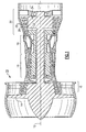
- one type of vane is a vane 40 provided with a large fillet.
- the large fillet 44 is formed to connect an airfoil 41 into end walls 43 and 39. As shown, a nominal portion of the airfoil 41 merges into end wall 43 through the large fillet 44.
- An upstream end 200 of the vane is shown, as is a downstream end 202 for orientation.
- the large fillet 44 curves upstream from the airfoil 41 into the end walls 43 and 39, and also curves circumferentially to each side of the airfoil 41.
- the large fillet extends for a relatively great amount of a radial extent of the airfoil.
- the large fillet is treated as part of the radial extent of the airfoil.
- the fillet 44 extends for approximately 25% of the overall radial extent, or span. Of course, this amount is only one example.
- the term "large fillet" can be taken as anything over 5% of the span,
- the vane 40 includes the airfoil 41 merging into the large fillet 44.
- So-called showerhead holes 60 extend through the airfoil portion 41.
- the showerhead holes 60 tend to extend through several rows spaced circumferentially by a small amount.
- Planes 62 can be defined by each circumferentially outermost row of showerhead holes 60.
- holes are formed within the large fillet 44. Holes fan circumferentially outwardly in both directions to define planes 64. Several rings can be defined including rings 1, 2, and 3 as illustrated in Figure 4 , and each ring includes more holes in the large fillet than the prior ring. Thus, five holes 66 are illustrated in ring 1, with 6 holes 68 in ring 2, and 7 holes 70 in ring 3. Of course, any number of holes can be utilized. In fact, the holes need not be arranged in rings. The main feature is to fan the holes circumferentially outwardly towards the curved sides 72 of the large fillet and beyond the planes 62 defined by the showerhead holes. In addition, as can be appreciated, the holes 66, 68, and 70 are staggered, such that they will cover a larger circumferential portion of the surface area.
- the size of the holes in the large fillet 44 may be smaller than the holes in the airfoil 41.
- the large fillet 44 will likely be dealing with cooler gasses than will the area having the showerhead, and thus the smaller holes may be acceptable.
- all holes could be the same size.
- the holes in the large fillet 44 could be larger than those in airfoil 41.
- the size of the holes is a function of how much cooling is required given the radial temperature profile from the products of combustion to which the airfoil is exposed. Also, manufacturing capabilities and gross size of the airfoil do come into play as well. Because end walls are typically cooler then the mid span, an optimized design may have the holes become smaller as you approach the end wall.
- Figure 5 shows another feature, wherein the holes 102 in the fillet 44 can be seen to exit at an angle ⁇ such that the exiting air is driven back against the outer skin of the large fillet by the products of combustion approaching the airfoil 41. Holes may exit the fillet at any angle but to reduce blow off and thus increase film adhesion and to increase the internal surface area of the film hole, the optimal configuration is to produce an array with the shallowest surface angles. This angle ⁇ is shown as being less than 90° to achieve this benefit.
- Film hole exit diffusion can be used to further enhance film effectiveness. This could include something other than constant cross section round holes. Instead, the holes can have something like a simple or compound angles to provide a diffusion angle.
- the fanning of the cooling hole array provides convective cooling for the largest portion of the fillet volume and minimizes the amount of cooling required. It also allows for the greatest amount of overall film coverage due to hole staggering along streamlines.
- a potential benefit of the fillet cooling hole array results from the additional air introduced near the end walls of the gas path. At these locations, a rich oxygen environment increases the likelihood that combustion is completed prior to entering the turbine. This has the potential to reduce the likelihood of unwanted downstream thermal phenomena when running at fuel rich operating points.
- a large fillet merges an airfoil into an end wall for a gas turbine engine component. While disclosed in a turbine vane, the invention would extend to blades. While a double vane is shown, the invention also extends to single vanes.
- the large fillet is provided with a cooling hole array, which fans outwardly from a cooling hole array in a nominal portion of the airfoil. In this manner, the large fillet is provided with better cooling than was the case in the prior art.
Landscapes
- Engineering & Computer Science (AREA)
- Mechanical Engineering (AREA)
- General Engineering & Computer Science (AREA)
- Turbine Rotor Nozzle Sealing (AREA)
Applications Claiming Priority (1)
| Application Number | Priority Date | Filing Date | Title |
|---|---|---|---|
| US12/033,918 US9322285B2 (en) | 2008-02-20 | 2008-02-20 | Large fillet airfoil with fanned cooling hole array |
Publications (3)
| Publication Number | Publication Date |
|---|---|
| EP2093382A2 true EP2093382A2 (de) | 2009-08-26 |
| EP2093382A3 EP2093382A3 (de) | 2012-04-18 |
| EP2093382B1 EP2093382B1 (de) | 2019-07-03 |
Family
ID=40347911
Family Applications (1)
| Application Number | Title | Priority Date | Filing Date |
|---|---|---|---|
| EP08253944.6A Active EP2093382B1 (de) | 2008-02-20 | 2008-12-10 | Bauteil eines gasturbinentriebwerks |
Country Status (2)
| Country | Link |
|---|---|
| US (1) | US9322285B2 (de) |
| EP (1) | EP2093382B1 (de) |
Cited By (2)
| Publication number | Priority date | Publication date | Assignee | Title |
|---|---|---|---|---|
| EP3181816A1 (de) * | 2015-12-07 | 2017-06-21 | General Electric Company | Schaufelprofil für ein gasturbinenkraftwerk, zugehöriges herstellungsverfahren und bauteil |
| EP3231999A1 (de) * | 2016-04-12 | 2017-10-18 | Siemens Aktiengesellschaft | Leitschaufel mit filmgekühltem schaufelblatt |
Families Citing this family (7)
| Publication number | Priority date | Publication date | Assignee | Title |
|---|---|---|---|---|
| US8727725B1 (en) * | 2009-01-22 | 2014-05-20 | Florida Turbine Technologies, Inc. | Turbine vane with leading edge fillet region cooling |
| US9243502B2 (en) | 2012-04-24 | 2016-01-26 | United Technologies Corporation | Airfoil cooling enhancement and method of making the same |
| US20130280093A1 (en) | 2012-04-24 | 2013-10-24 | Mark F. Zelesky | Gas turbine engine core providing exterior airfoil portion |
| US9296039B2 (en) | 2012-04-24 | 2016-03-29 | United Technologies Corporation | Gas turbine engine airfoil impingement cooling |
| US10352180B2 (en) | 2013-10-23 | 2019-07-16 | General Electric Company | Gas turbine nozzle trailing edge fillet |
| US10227876B2 (en) | 2015-12-07 | 2019-03-12 | General Electric Company | Fillet optimization for turbine airfoil |
| US10927689B2 (en) | 2018-08-31 | 2021-02-23 | Rolls-Royce Corporation | Turbine vane assembly with ceramic matrix composite components mounted to case |
Citations (4)
| Publication number | Priority date | Publication date | Assignee | Title |
|---|---|---|---|---|
| EP1647672A2 (de) * | 2004-10-18 | 2006-04-19 | United Technologies Corporation | Schaufel mit prallgekühltem Übergang von grossem Krümmungsradius |
| EP1669544A1 (de) * | 2004-12-13 | 2006-06-14 | The General Electric Company | Turbinenstufe mit filmgekühlter Übergangskontur |
| EP1688587A2 (de) * | 2005-01-10 | 2006-08-09 | General Electric Company | Turbinenstufe mit trichterförmigem Übergang |
| US7621718B1 (en) * | 2007-03-28 | 2009-11-24 | Florida Turbine Technologies, Inc. | Turbine vane with leading edge fillet region impingement cooling |
Family Cites Families (13)
| Publication number | Priority date | Publication date | Assignee | Title |
|---|---|---|---|---|
| GB1564608A (en) | 1975-12-20 | 1980-04-10 | Rolls Royce | Means for cooling a surface by the impingement of a cooling fluid |
| US4712979A (en) | 1985-11-13 | 1987-12-15 | The United States Of America As Represented By The Secretary Of The Air Force | Self-retained platform cooling plate for turbine vane |
| US5344283A (en) | 1993-01-21 | 1994-09-06 | United Technologies Corporation | Turbine vane having dedicated inner platform cooling |
| US5394687A (en) | 1993-12-03 | 1995-03-07 | The United States Of America As Represented By The Department Of Energy | Gas turbine vane cooling system |
| JP3316405B2 (ja) | 1997-02-04 | 2002-08-19 | 三菱重工業株式会社 | ガスタービン冷却静翼 |
| US5762471A (en) | 1997-04-04 | 1998-06-09 | General Electric Company | turbine stator vane segments having leading edge impingement cooling circuits |
| JP3316418B2 (ja) * | 1997-06-12 | 2002-08-19 | 三菱重工業株式会社 | ガスタービン冷却動翼 |
| FR2765265B1 (fr) | 1997-06-26 | 1999-08-20 | Snecma | Aubage refroidi par rampe helicoidale, par impact en cascade et par systeme a pontets dans une double peau |
| US7281895B2 (en) | 2003-10-30 | 2007-10-16 | Siemens Power Generation, Inc. | Cooling system for a turbine vane |
| JP4346412B2 (ja) * | 2003-10-31 | 2009-10-21 | 株式会社東芝 | タービン翼列装置 |
| US7025563B2 (en) | 2003-12-19 | 2006-04-11 | United Technologies Corporation | Stator vane assembly for a gas turbine engine |
| US7322796B2 (en) | 2005-08-31 | 2008-01-29 | United Technologies Corporation | Turbine vane construction |
| US7334985B2 (en) * | 2005-10-11 | 2008-02-26 | United Technologies Corporation | Shroud with aero-effective cooling |
-
2008
- 2008-02-20 US US12/033,918 patent/US9322285B2/en active Active
- 2008-12-10 EP EP08253944.6A patent/EP2093382B1/de active Active
Patent Citations (4)
| Publication number | Priority date | Publication date | Assignee | Title |
|---|---|---|---|---|
| EP1647672A2 (de) * | 2004-10-18 | 2006-04-19 | United Technologies Corporation | Schaufel mit prallgekühltem Übergang von grossem Krümmungsradius |
| EP1669544A1 (de) * | 2004-12-13 | 2006-06-14 | The General Electric Company | Turbinenstufe mit filmgekühlter Übergangskontur |
| EP1688587A2 (de) * | 2005-01-10 | 2006-08-09 | General Electric Company | Turbinenstufe mit trichterförmigem Übergang |
| US7621718B1 (en) * | 2007-03-28 | 2009-11-24 | Florida Turbine Technologies, Inc. | Turbine vane with leading edge fillet region impingement cooling |
Cited By (4)
| Publication number | Priority date | Publication date | Assignee | Title |
|---|---|---|---|---|
| EP3181816A1 (de) * | 2015-12-07 | 2017-06-21 | General Electric Company | Schaufelprofil für ein gasturbinenkraftwerk, zugehöriges herstellungsverfahren und bauteil |
| CN107013329A (zh) * | 2015-12-07 | 2017-08-04 | 通用电气公司 | 具有填角膜孔的燃气涡轮发动机 |
| CN107013329B (zh) * | 2015-12-07 | 2019-11-19 | 通用电气公司 | 用于燃气涡轮发动机的翼型件 |
| EP3231999A1 (de) * | 2016-04-12 | 2017-10-18 | Siemens Aktiengesellschaft | Leitschaufel mit filmgekühltem schaufelblatt |
Also Published As
| Publication number | Publication date |
|---|---|
| EP2093382A3 (de) | 2012-04-18 |
| US9322285B2 (en) | 2016-04-26 |
| US20090208325A1 (en) | 2009-08-20 |
| EP2093382B1 (de) | 2019-07-03 |
Similar Documents
| Publication | Publication Date | Title |
|---|---|---|
| EP2093382B1 (de) | Bauteil eines gasturbinentriebwerks | |
| US20200024964A1 (en) | Cooling hole for a gas turbine engine component | |
| US10830073B2 (en) | Vane assembly of a gas turbine engine | |
| US9273563B2 (en) | Integrally bladed rotor with slotted outer rim | |
| US9650900B2 (en) | Gas turbine engine components with film cooling holes having cylindrical to multi-lobe configurations | |
| US10822971B2 (en) | Cooling hole for a gas turbine engine component | |
| US10641110B2 (en) | Turbine disk | |
| EP2861909A2 (de) | Gasturbinenmotorwand | |
| US10920591B2 (en) | Turbine disk | |
| US7726944B2 (en) | Turbine blade with improved durability tip cap | |
| EP3042041B1 (de) | Gasturbinenmotorflügelturbulator für flügelkriechbeständigkeit | |
| US10550702B2 (en) | Turbine disk | |
| US10724374B2 (en) | Turbine disk | |
| US10544677B2 (en) | Turbine disk | |
| US20130195643A1 (en) | Stress relieving slots for turbine vane ring | |
| EP2885503B1 (de) | Integral beschaufelter rotor | |
| US9506351B2 (en) | Durable turbine vane | |
| US11879357B2 (en) | Turbine blade for a gas turbine engine | |
| US10731477B2 (en) | Woven skin cores for turbine airfoils |
Legal Events
| Date | Code | Title | Description |
|---|---|---|---|
| PUAI | Public reference made under article 153(3) epc to a published international application that has entered the european phase |
Free format text: ORIGINAL CODE: 0009012 |
|
| AK | Designated contracting states |
Kind code of ref document: A2 Designated state(s): AT BE BG CH CY CZ DE DK EE ES FI FR GB GR HR HU IE IS IT LI LT LU LV MC MT NL NO PL PT RO SE SI SK TR |
|
| AX | Request for extension of the european patent |
Extension state: AL BA MK RS |
|
| PUAL | Search report despatched |
Free format text: ORIGINAL CODE: 0009013 |
|
| AK | Designated contracting states |
Kind code of ref document: A3 Designated state(s): AT BE BG CH CY CZ DE DK EE ES FI FR GB GR HR HU IE IS IT LI LT LU LV MC MT NL NO PL PT RO SE SI SK TR |
|
| AX | Request for extension of the european patent |
Extension state: AL BA MK RS |
|
| RIC1 | Information provided on ipc code assigned before grant |
Ipc: F01D 5/18 20060101ALI20120314BHEP Ipc: F01D 9/04 20060101AFI20120314BHEP |
|
| 17P | Request for examination filed |
Effective date: 20121012 |
|
| AKX | Designation fees paid |
Designated state(s): DE GB |
|
| RAP1 | Party data changed (applicant data changed or rights of an application transferred) |
Owner name: UNITED TECHNOLOGIES CORPORATION |
|
| 17Q | First examination report despatched |
Effective date: 20170907 |
|
| GRAP | Despatch of communication of intention to grant a patent |
Free format text: ORIGINAL CODE: EPIDOSNIGR1 |
|
| INTG | Intention to grant announced |
Effective date: 20180904 |
|
| GRAJ | Information related to disapproval of communication of intention to grant by the applicant or resumption of examination proceedings by the epo deleted |
Free format text: ORIGINAL CODE: EPIDOSDIGR1 |
|
| GRAP | Despatch of communication of intention to grant a patent |
Free format text: ORIGINAL CODE: EPIDOSNIGR1 |
|
| INTC | Intention to grant announced (deleted) | ||
| INTG | Intention to grant announced |
Effective date: 20190213 |
|
| GRAJ | Information related to disapproval of communication of intention to grant by the applicant or resumption of examination proceedings by the epo deleted |
Free format text: ORIGINAL CODE: EPIDOSDIGR1 |
|
| GRAR | Information related to intention to grant a patent recorded |
Free format text: ORIGINAL CODE: EPIDOSNIGR71 |
|
| GRAS | Grant fee paid |
Free format text: ORIGINAL CODE: EPIDOSNIGR3 |
|
| INTC | Intention to grant announced (deleted) | ||
| GRAA | (expected) grant |
Free format text: ORIGINAL CODE: 0009210 |
|
| INTG | Intention to grant announced |
Effective date: 20190522 |
|
| AK | Designated contracting states |
Kind code of ref document: B1 Designated state(s): DE GB |
|
| REG | Reference to a national code |
Ref country code: GB Ref legal event code: FG4D |
|
| REG | Reference to a national code |
Ref country code: DE Ref legal event code: R096 Ref document number: 602008060573 Country of ref document: DE |
|
| REG | Reference to a national code |
Ref country code: DE Ref legal event code: R097 Ref document number: 602008060573 Country of ref document: DE |
|
| PLBE | No opposition filed within time limit |
Free format text: ORIGINAL CODE: 0009261 |
|
| STAA | Information on the status of an ep patent application or granted ep patent |
Free format text: STATUS: NO OPPOSITION FILED WITHIN TIME LIMIT |
|
| 26N | No opposition filed |
Effective date: 20200603 |
|
| REG | Reference to a national code |
Ref country code: DE Ref legal event code: R081 Ref document number: 602008060573 Country of ref document: DE Owner name: RAYTHEON TECHNOLOGIES CORPORATION (N.D.GES.D.S, US Free format text: FORMER OWNER: UNITED TECHNOLOGIES CORPORATION, FARMINGTON, CONN., US |
|
| P01 | Opt-out of the competence of the unified patent court (upc) registered |
Effective date: 20230519 |
|
| PGFP | Annual fee paid to national office [announced via postgrant information from national office to epo] |
Ref country code: GB Payment date: 20231121 Year of fee payment: 16 |
|
| PGFP | Annual fee paid to national office [announced via postgrant information from national office to epo] |
Ref country code: DE Payment date: 20231121 Year of fee payment: 16 |