EP2093349B1 - Vorrichtung zum Anbringen einer Spachtelmasse auf den Papierstreifen einer Eckschutzleiste für Trockenbauplatten - Google Patents
Vorrichtung zum Anbringen einer Spachtelmasse auf den Papierstreifen einer Eckschutzleiste für Trockenbauplatten Download PDFInfo
- Publication number
- EP2093349B1 EP2093349B1 EP09002550.3A EP09002550A EP2093349B1 EP 2093349 B1 EP2093349 B1 EP 2093349B1 EP 09002550 A EP09002550 A EP 09002550A EP 2093349 B1 EP2093349 B1 EP 2093349B1
- Authority
- EP
- European Patent Office
- Prior art keywords
- gate
- tray
- base
- bead
- opening
- Prior art date
- Legal status (The legal status is an assumption and is not a legal conclusion. Google has not performed a legal analysis and makes no representation as to the accuracy of the status listed.)
- Active
Links
Images




Classifications
-
- E—FIXED CONSTRUCTIONS
- E04—BUILDING
- E04F—FINISHING WORK ON BUILDINGS, e.g. STAIRS, FLOORS
- E04F21/00—Implements for finishing work on buildings
- E04F21/165—Implements for finishing work on buildings for finishing joints, e.g. implements for raking or filling joints, jointers
-
- E—FIXED CONSTRUCTIONS
- E04—BUILDING
- E04F—FINISHING WORK ON BUILDINGS, e.g. STAIRS, FLOORS
- E04F21/00—Implements for finishing work on buildings
- E04F21/02—Implements for finishing work on buildings for applying plasticised masses to surfaces, e.g. plastering walls
- E04F21/026—Implements for finishing work on buildings for applying plasticised masses to surfaces, e.g. plastering walls for applying adhesive or joint compound to joint tapes, in particular drywall tapes
-
- E—FIXED CONSTRUCTIONS
- E04—BUILDING
- E04F—FINISHING WORK ON BUILDINGS, e.g. STAIRS, FLOORS
- E04F21/00—Implements for finishing work on buildings
- E04F21/165—Implements for finishing work on buildings for finishing joints, e.g. implements for raking or filling joints, jointers
- E04F21/1655—Implements for finishing work on buildings for finishing joints, e.g. implements for raking or filling joints, jointers for finishing corner joints
-
- E—FIXED CONSTRUCTIONS
- E04—BUILDING
- E04F—FINISHING WORK ON BUILDINGS, e.g. STAIRS, FLOORS
- E04F21/00—Implements for finishing work on buildings
- E04F21/165—Implements for finishing work on buildings for finishing joints, e.g. implements for raking or filling joints, jointers
- E04F21/1657—Implements for finishing work on buildings for finishing joints, e.g. implements for raking or filling joints, jointers for applying tape to joints, e.g. drywall taper tools
-
- Y—GENERAL TAGGING OF NEW TECHNOLOGICAL DEVELOPMENTS; GENERAL TAGGING OF CROSS-SECTIONAL TECHNOLOGIES SPANNING OVER SEVERAL SECTIONS OF THE IPC; TECHNICAL SUBJECTS COVERED BY FORMER USPC CROSS-REFERENCE ART COLLECTIONS [XRACs] AND DIGESTS
- Y10—TECHNICAL SUBJECTS COVERED BY FORMER USPC
- Y10T—TECHNICAL SUBJECTS COVERED BY FORMER US CLASSIFICATION
- Y10T156/00—Adhesive bonding and miscellaneous chemical manufacture
- Y10T156/17—Surface bonding means and/or assemblymeans with work feeding or handling means
- Y10T156/1788—Work traversing type and/or means applying work to wall or static structure
- Y10T156/179—Work traversing type and/or means applying work to wall or static structure with liquid applying means
-
- Y—GENERAL TAGGING OF NEW TECHNOLOGICAL DEVELOPMENTS; GENERAL TAGGING OF CROSS-SECTIONAL TECHNOLOGIES SPANNING OVER SEVERAL SECTIONS OF THE IPC; TECHNICAL SUBJECTS COVERED BY FORMER USPC CROSS-REFERENCE ART COLLECTIONS [XRACs] AND DIGESTS
- Y10—TECHNICAL SUBJECTS COVERED BY FORMER USPC
- Y10T—TECHNICAL SUBJECTS COVERED BY FORMER US CLASSIFICATION
- Y10T156/00—Adhesive bonding and miscellaneous chemical manufacture
- Y10T156/17—Surface bonding means and/or assemblymeans with work feeding or handling means
- Y10T156/1788—Work traversing type and/or means applying work to wall or static structure
- Y10T156/1795—Implement carried web supply
Definitions
- the present invention relates generally to construction using gypsum wallboard, and more particularly, to an apparatus used to apply joint compound to corner paper beads prior to their attachment to joints or corners between adjacent wallboard panels.
- Corner beads are elongated, narrow strips of metal or plastic, often having a paper face on one side, and are typically folded or angled along their longitudinal center line to produce a generally v-shaped cross-section. They are made with various angles and corner shapes, including 90-degree angle corners and rounded or so-called "bullnose" corners of various angles. Corner beads are also designed for covering both inside (concave) and outside (convex) corners. For application to an inside corner, joint compound is applied to the outside (convex) faces of an inside corner bead. For application to an outside corner, joint compound is applied to the inside (concave) faces of an outside corner bead. Joint compound is applied to the appropriate faces of the bead, and the bead is then pressed against the corner, with the joint compound forming an adhesive joint between the corner bead and the wallboard corner.
- Hopper devices have been used to reduce the time needed to apply joint compound to the paper bead and provide for a cleaner process.
- Such devices typically include a hopper retaining a supply of wallboard joint compound, and a passageway in a bottom of the container where the corner bead is passed through the passageway to receive a coating of joint compound and to provide a guide for locating the corner bead.
- US 2007/261334 A1 discloses a device for applying drywall compound to a length of corner bead, featuring a common five-gallon bucket and its lid as hopper and lid.
- Two design criteria of such a device are to increase efficiency and increase cleanliness when applying joint compound to a corner bead. Further, since joint compound generally has a highly viscous property and some compounds set rapidly, it is often difficult to remove unwanted joint compound from the hopper upon completion of a job. Thus, another design criteria of such a device is the ability to readily remove unwanted joint compound.
- the present paper beading apparatus which features a hopper having a lid that provides a seal over the hopper, thus preventing joint compound from inadvertently escaping out of the hopper.
- a releasably sealable air port is provided on the lid, which allows a batch of unused joint compound to be stored overnight without setting.
- the hopper also has an obstruction-free floor which allows for easy cleaning and further is supported by a base, which features a set of rings having spaced, stepped fins for accommodating support buckets of varying dimensions, thereby reducing the likelihood of the beading apparatus being inadvertently knocked over, causing joint compound to leak out.
- the apparatus also features a single, reversible tray that allows for the application of joint compound to either an inside corner bead or an outside corner bear, depending on the tray's orientation.
- a mouth at each end of the tray is elongated to reduce dripping of joint compound and to provide a guide for locating the bead in the tray.
- the apparatus also features an internal gate having an application portion and a reinforcement portion, each made of distinctive materials.
- a positioning lug is provided on the gate for engaging a positioning opening on a base, thereby assisting a user in correctly position the gate in the base.
- a paper beading apparatus which includes a hopper having a body defining a chamber for holding a quantity of joint compound, and having an open upper end, an upper rim, and a lower end. Further included is a lid pivotally secured to the body for movement between an open position and a closed position, wherein in the closed position, the lid engages the open upper rim. The lid also includes a releasably sealable air port. Further included is a base configured for and accommodating the hopper lower end, for receiving joint compound, and for applying the joint compound to a corner paper bead.
- a second embodiment of the present invention is a paper beading apparatus which includes a hopper having a body defining a chamber for holding a quantity of joint compound and a floor having a depending skirt defining a discharge opening.
- the apparatus further includes a base configured for receiving the hopper and defining a cavity, a front bead opening, and a rear bead opening at opposite ends of the base and in communication with the cavity, and an inlet chute defining an inlet opening in communication with the discharge opening.
- a tray for use in a paper beading apparatus for applying joint compound to a corner bead having a base defining a cavity and having at least one tray track.
- the tray includes at least two flanges, each flange being generally parallel and equidistant from both a tray upper plane and a tray lower plane, the tray being reversible along a longitudinal axis of the tray and having two positions, an outside bead position wherein the tray has a generally "M"-shape when viewed on end and an inside bead position wherein the tray has a generally "W"-shape when viewed on end, and wherein the at least one tray track each accommodates a corresponding one of the tray flanges when the tray is in either the outside bead position or the inside bead position, the tray being disposed in the cavity.
- a gate for use with a paper beading apparatus for applying joint compound to a corner bead having a base defining a cavity and at least one gate positioning opening, and a tray being disposed in the cavity.
- the gate includes at least one gate application edge, a plurality of gate teeth disposed on the at least one application edge, and at least one positioning lug.
- the gate is disposed in the cavity with the at least one positioning lug engaging the corresponding gate positioning opening, and is arranged such that a bead gap is formed between the at least one gate application edge and the tray.
- the corner bead is fed through the bead gap such that it makes contact with the gate teeth, the at least one gate application edge defining the amount of joint compound dispensed on the corner bead.
- a paper beading apparatus generally designated 10 has a hopper 12 with a lid 14, the hopper being attached to a base 16.
- the hopper 12 has a body 18 defining a chamber 20 for holding a quantity of joint compound.
- On the hopper 12 is an open upper end 22, an upper rim 24, and a lower end 26.
- At least two hand holds 28 are disposed on the body 18 near the open upper end 22, for facilitating lifting and/or movement of the paper beading apparatus 10.
- the hand holds 28 are on diametrically opposite sides of the apparatus 10 and are disposed on an annular rib or lip 30, extending radially from a longitudinal axis of the hopper 12.
- the annular rib 30 is preferably disposed near the open upper rim 24.
- An alternative way to lift and/or move the paper beading apparatus 10 is provided by way of a handle 32 having two ends, a handle first end 34 preferably being attached to one of the hand holds 28, and a handle second end 36 being attached to the other hand hold.
- each handle end 34, 36 is pivotally fastened to the corresponding hand hold 28 at a pivot point 38.
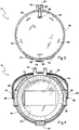
- the lid 14 ( FIG. 3 ) is pivotally secured to the body 18 for movement between an open position and a closed position. In the closed position, the lid 14 engages the hopper upper rim 24, generally forming a seal over the open upper end 22.
- An adjustable hinge 42 is constructed and arranged such that the lid 14 pivots on the hinge between the open position and the closed position.
- the hinge 42 is made up of a hinge body portion 44, preferably extending from the annular rib 30, which generally complements and engages a hinge lid portion 46, preferably extending from an outer rim 48 of the lid 14.
- An adjustable hinge clamp 49 for varying a clamping force executed on the lid 14 has a clamp knob 50 with a threaded bore and a threaded bolt 51 that passes through at least one hinge fastener opening 52 in each of the hinge body portion 44 and the hinge lid portion 46.
- the lid 14 Upon tightening the hinge clamp 49, the lid 14 incurs greater resistance in moving between the open position and the closed position, thereby allowing a user to control the ease with which the lid moves about the hinge 42. As such, the user can tighten the hinge clamp 49 sufficiently such that the lid 14 does not freely rotate about the hinge 42, but instead remains in a fixed position. Upon removing the hinge clamp 49, the lid 14 can be completely removed from the hopper 12.
- a latch 54 preferably of the over center cam or toggle type and being attached to the body 18 near the open upper end 22, has a latched position and an unlatched position and rotates on a latch attaching extension 56 on the body 18, preferably near the open upper end 22.
- the latch clamps the lid to the body 18 such that the lid sealingly engages the open upper end 22.
- the latch 54 clamps the lid 14 to the body 18 by grippingly engaging a latch receiving lip 58 on the lid. Variations in the configuration of the latch 54 are contemplated.
- At least one, but preferably five lid ribs 60 extend from a top side 62 of the lid 14.
- the lid ribs 60 instead of the top side 62, make contact with the surface.
- the top side 62 has a reduced likelihood of sustaining wear.
- a releasably sealable, preferably circular air port 64 is also on the lid 14 .
- a stopper 66 is tethered to the lid 14 and has a generally peg-shaped air plug 68 constructed and arranged to releasably seal the air port 64. It is noted that the stopper 66 could alternatively be tethered to the body 18.
- the lid 14 also has at least one, but preferably two grips 70 extending radially from an edge 72 of the lip 14, which provides the user with an increased surface area for gripping the lid 14 when moving the lid between the open position and the closed position.
- a feature of the hopper 12 is a preferably obstruction-free floor 72 having a depending skirt 74 that defines a discharge opening 76.
- the chamber 20 is much easier to clean with a standard taping knife compared to a conventional beading apparatus.
- the base 16 which is configured for and accommodates the hopper lower end 26.
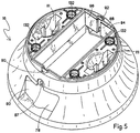
- the base 16 defines a cavity 78, a front bead opening 80 and a rear bead opening 82 ( FIG. 8 ) at opposite ends of the base and in communication with the cavity, and an inlet chute 84 defining an inlet opening 86 being in communication with the discharge opening 76.
- the inlet opening 86 and the discharge opening 76 are generally rectangular-shaped having generally equivalent dimensions.
- the skirt 74 preferably telescopes into the opening 86.
- the base 16 also defines at least two gate adjustment slots, a front gate adjustment slot 87 being adjacent to the front bead opening 80 and a rear gate adjustment slot 88 being adjacent to the rear bead opening 82 ( FIG. 5 ). Further defined by the base 16 are at least two gate positioning openings, a front gate positioning opening 90 being adjacent to the front gate adjustment slot 87 and a rear gate positioning opening 92 being adjacent to the rear gate adjustment slot 88.
- each gate 94 has at least one gate fastener opening 95, at least one, but preferably two application edges 96 with a plurality of gate teeth 97 preferably with beveled edges 98 or rounded edges (not shown), and at least one positioning lug 99.
- each gate 94 includes an application portion 100 and a reinforcement portion 102, each portion being made of a different material.
- the application portion 100 is made of thermoplastic elastomer material similar to a stiff rubber and the reinforcement portion 102 is made of a relatively hard plastic material, with the two portions being chemically and/or mechanically bonded together to form an integrated piece.
- the application portion 100 has at least one, but preferably several lugs 108 having a variety of shapes, and extending into and mating with the reinforcement portion 102.
- the lugs 108 provide for mechanical bonding by having a frictional fit and a mating engagement in their corresponding openings in the reinforcement portion 102 ( FIG. 6 ).
- Chemical bonding is achieved by heating or applying chemical adhesive to the two portions 100, 102.
- Extending from a rear surface 109 of the gate 94 is at least one, but preferably two gate fins 110 preferably made of a soft plastic material.
- the base 16 also defines at least one gate storage compartment 111 ( FIG. 2B ) for conveniently storing spare gates 94.
- the gate fins 110 engage the inside of the gate storage compartment 111 with a friction fit to reduce gate movement.
- Each gate 94 is arranged such that the positioning lug 99 engages the corresponding gate positioning opening 90, 92, the track-like openings being constructed and arranged to allow the gate 94 to be vertically adjustable.
- Each gate 94 is securable by an at least one elongate threaded gate fastener 112 and a threaded knob 116, with the elongate portion passing though the gate fastener opening 95 at a desired vertical position, and the corresponding gate adjustment slot 87, 88 to engage the knob 116, allowing the gate 94 to be secured at a desired vertical position.
- an elongate tray 118 having at least two laterally extending flanges 120, each flange being generally parallel and equidistant from both a tray upper plane extremity and a tray lower extremity ( FIG. 2B ).
- a feature of the tray 118 is that it is reversible along a longitudinal axis of the tray to have two operational positions, an outside bead position where the tray has a generally "M"-shape when viewed on end, and an inside bead position where the tray has a generally "W"-shape when viewed on end.
- the tray 118 has at least one, but preferably two mouths 126 located at each tray end 128, extending along the longitudinal axis beyond the flanges 120.
- Each mouth 126 is elongated to reduce dripping of joint compound and to provide a guide for locating the bead in the tray.
- the base 16 also has at least one, but preferably four base fastener openings 132 ( FIG. 5 ), with the body 18 having at least one, but preferably four bosses 133 ( FIG. 2A ).
- At least one, but preferably four tray fasteners 134 are constructed and arranged to fasten the tray 118, in either the outside bead position or the inside bead position, the base 16, and the body 18 together by passing through the corresponding tray fastener opening 130 and the corresponding base fastener opening 132 to engage the corresponding boss 133, which retains a threaded nut (not shown).
- a bead gap 136 ( FIG. 1 ) is formed between the at least one gate application edge 96 of each gate 94 and the tray.
- the corner bead is able to be fed through the bead gap 136 such that it makes contact with the gate teeth 97, with the gate application edge 96 defining the amount of joint compound dispensed on the corner bead.
- different shaped gate application edges are preferred for different types of corner beading jobs. For example, a gate 94 with a ninety-degree shaped application edge 96 is generally preferred for use with a ninety-degree shaped corner bead.
- a gate 94b has a bull-nose shaped application edge 96b ( FIG. 2B ), which is generally preferred for use with a bull-nose shaped corner bead.
- an inside corner gate 94c has a distinctive, concave right-angled shape 96c ( FIG. 3 ).
- the base 16 can simply be placed on a floor or other generally solid surface when being used, preferably the base has a lower peripheral edge 138 configured for engaging a substrate, wherein the base has at least one ring 140 of spaced, stepped fins 142 disposed inwardly from the peripheral edge for accommodating a support bucket.
- the base has a plurality of rings 140 being radially spaced apart for facilitating engagement with support buckets of varying diameters. Each step defines a landing or engagement point for a support bucket with a different diameter.
Landscapes
- Engineering & Computer Science (AREA)
- Architecture (AREA)
- Civil Engineering (AREA)
- Structural Engineering (AREA)
- Closures For Containers (AREA)
- Paper (AREA)
- Conveying And Assembling Of Building Elements In Situ (AREA)
- Coating Apparatus (AREA)
Claims (11)
- Vorrichtung (10) zum Anbringen einer Spachtelmasse auf einen Papierstreifen einer Eckschutzleiste, umfassend:einen Trichter (12) mit einem Korpus (18), der eine Kammer (20) zum Halten einer Menge Fugenmasse definiert, die ein offenes oberes Ende (22), einen oberen Rand (24) und ein unteres Ende (26) aufweist;dadurch gekennzeichnet, dassder Trichter mit einem Deckel (14) versehen ist, der beweglich an dem Körper (18) so befestigt ist, dass er sich zwischen einer offenen Position und einer geschlossenen Position bewegen kann, wobei der Deckel in der geschlossenen Position an den offenen oberen Rand angreift, wobei der Deckel eine lösbar abdichtbare Luftschleuse (64) aufweist; undeine Basis (16), die für das untere Ende (26) des Trichters konfiguriert ist und dieses beherbergt, zur Aufnahme der Fugenmasse und zum Anbringen der Fugenmasse auf einem Papierstreifen einer Eckschutzleiste.
- Vorrichtung gemäß Anspruch 1, weiterhin umfassend einen Stopfen (66), der entweder an den Deckel (14) oder an den Korpus (18) angebunden ist und einen im Wesentlichen zapfenförmigen Luftpfropfen (68) aufweist, der so aufgebaut und angeordnet ist, dass er die Luftschleuse (64) lösbar abdichtet.
- Vorrichtung gemäß Anspruch 1 oder 2, weiterhin umfassend:wenigstens zwei Handgriffe (28), die sich jeweils an dem Korpus (18) in der Nähe der offenen oberen Enden des Trichters befinden; undeinen Griff (32) mit zwei Enden, einem ersten Ende (34) des Griffs, das an einem der wenigstens zwei Handgriffe (28) befestigt ist, und einem zweiten Ende (36) des Griffs, das an dem anderen der wenigstens zwei Handgriffe (28) befestigt ist.
- Vorrichtung gemäß einem der Ansprüche 1 bis 3, weiterhin umfassend ein Scharnier (42), das so aufgebaut und angeordnet ist, dass es den Deckel (14) mit dem Trichter (12) verbindet, so dass der Deckel an dem Scharnier zwischen der offenen Position und der geschlossenen Position schwenkt, wobei das Scharnier eine einstellbare Klemme (49) umfasst, um die auf den Deckel ausgeübte Klemmkraft zu variieren, und/oder weiterhin einen Riegel (54) umfasst, der an dem Korpus (18) in der Nähe des oberen Endes (22) des Trichters befestigt ist und eine verriegelte Position und eine nichtverriegelte Position aufweist, wobei der Riegel, wenn sich der Deckel in der geschlossenen und der Riegel in der verriegelten Position befinden, den Deckel auf den Korpus klemmt, wobei der Deckel abdichtend an das offene obere Ende des Trichters angreift.
- Vorrichtung gemäß einem der Ansprüche 1 bis 4, wobei die Basis (16) einen Hohlraum (78) aufweist und die Vorrichtung weiterhin umfasst:eine Wanne (118), die sich in dem Hohlraum der Basis befindet;einen Schieber (94), der wenigstens eine Auftragungskante (96) mit einer Vielzahl von Schieberzähnen (97) aufweist; undwobei sich der Schieber im Hohlraum der Basis befindet und so angeordnet ist, dass eine Schutzleistenlücke (136) zwischen der wenigstens einen Auftragungskante des Schiebers und der Wanne entsteht, wodurch die Eckschutzleiste durch die Schutzleistenlücke geführt wird, so dass die Eckschutzleiste so mit den Schieberzähnen in Kontakt kommt, dass die Fugenmasse auf die Eckschutzleiste aufgebracht wird.
- Vorrichtung gemäß einem der Ansprüche 1 bis 5, weiterhin umfassend:dass der Trichter (12) einen Boden (72) aufweist, der einen herabhängenden Unterteil (74) aufweist, welcher eine Entleerungsöffnung (76) definiert; unddass die Basis (16) so konfiguriert ist, dass sie den Trichter aufnehmen kann und einen Hohlraum (78), eine vordere Schutzleistenöffnung (80) und eine hintere Schutzleistenöffnung (82) an entgegengesetzten Enden der Basis in Kommunikation mit dem Hohlraum definiert, und ein Einlaufschacht eine Einlauföffnung in Kommunikation mit der Entleerungsöffnung definiert.
- Vorrichtung gemäß Anspruch 6, wobei die Basis (16) eine niedrigere umlaufende Kante (138) aufweist, die so konfiguriert ist, dass sie an ein Substrat angreift, wobei die Basis wenigstens einen Ring (140) aus beabstandeten, gestuften Lamellen (142) aufweist, die ausgehend von der umlaufenden Kante nach innen angeordnet sind, um einen Trägereimer unterzubringen, wobei die Basis (16) eine Vielzahl der Ringe (140) aufweist, die radial voneinander beabstandet sind, um das Aufstecken von Trägereimern verschiedener Durchmesser zu erleichtern, und/oder wobei die Basis weiterhin wenigstens ein Schieberparkkompartiment (111) definiert.
- Vorrichtung gemäß Anspruch 6 oder 7, weiterhin umfassend eine längliche Wanne (118), die wenigstens zwei Flansche (120) aufweist, wobei jeder Flansch im Wesentlichen parallel zu und äquidistant von sowohl einer oberen Ebene der Wanne (122) als auch einer unteren Ebene der Wanne (124) verläuft, wobei die Wanne entlang einer Längsachse der Wanne umgedreht werden kann und zwei Positionen aufweist, eine Außenschutzleistenposition, wobei die Wanne im Wesentlichen eine "M"-Form aufweist, wenn man vom Ende aus darauf sieht, und eine Innenschutzleistenposition, wobei die Wanne im Wesentlichen eine "W"-Form aufweist, wenn man vom Ende aus darauf sieht, wobei sich die Wanne im Hohlraum der Basis befindet.
- Vorrichtung gemäß Anspruch 8, wobei die Basis (16) wenigstens eine Basisbefestigungsöffnung (132) aufweist, wobei die Wanne wenigstens eine Wannenbefestigungsöffnung (130) aufweist und der Korpus (18) wenigstens einen Knauf (133) aufweist, wobei wenigstens eine Wannenbefestigung (134) so aufgebaut und angeordnet ist, dass sie, dadurch dass sie wenigstens eine Wannenbefestigungsöffnung und die entsprechende Befestigungsöffnung passiert, die Wanne entweder in der Außenschutzleistenposition oder in der Innenschutzleistenposition, die Basis und den Korpus aneinander befestigt, um an den entsprechenden Knauf anzugreifen, und/oder wobei die Wanne (118) wenigstens einen Ausguss (126) aufweist, der sich an einem Ende der Wanne befindet und sich entlang der Längsachse über die wenigstens zwei Flansche (120) hinaus erstreckt.
- Vorrichtung gemäß einem der Ansprüche 6 bis 9, wobei die Basis weiterhin wenigstens zwei Schiebereinstellungsschlitze definiert, wobei sich ein vorderer Schiebereinstellungsschlitz (87) neben der vorderen Schutzleistenöffnung befindet und sich ein hinterer Schiebereinstellungsschlitz (88) neben der hinteren Schutzleistenöffnung (82) befindet, wobei die Basis weiterhin wenigstens zwei Schieberpositionierungsöffnungen definiert, wobei sich eine vordere Schieberpositionierungsöffnung (90) neben dem vorderen Schiebereinstellungsschlitz (87) befindet und sich eine hintere Schieberpositionierungsöffnung (92) neben dem hinteren Schiebereinstellungsschlitz (88) befindet.
- Vorrichtung gemäß einem der Ansprüche 6 bis 10, weiterhin umfassend:wenigstens eine Schieberbefestigung (112);wenigstens einen Schieber (94) mit einer Schieberbefestigungsöffnung (95), wenigstens einer Auftragungskante (96) und wenigstens einer Positionierungslasche (99); undwobei sich der wenigstens eine Schieber in dem Hohlraum (78) befindet, wobei die wenigstens eine Positionierungslasche in die entsprechende Schieberpositionierungsöffnung eingreift, die so aufgebaut und angeordnet ist, dass der Schieber in der Öffnung vertikal einstellbar ist und durch die wenigstens eine Gatterbefestigung befestigt werden kann, und/oder wobei der Trichterboden (72) frei von Verstopfung ist.
Priority Applications (1)
| Application Number | Priority Date | Filing Date | Title |
|---|---|---|---|
| SI201230898A SI2093349T1 (sl) | 2008-02-25 | 2009-02-24 | Aparat za nanašanje mase za kitanje na papirne trakove vogalnikov zidnih plošč |
Applications Claiming Priority (1)
| Application Number | Priority Date | Filing Date | Title |
|---|---|---|---|
| US12/036,847 US8042591B2 (en) | 2008-02-25 | 2008-02-25 | Paper beading apparatus for wallboard corner beads |
Publications (3)
| Publication Number | Publication Date |
|---|---|
| EP2093349A2 EP2093349A2 (de) | 2009-08-26 |
| EP2093349A3 EP2093349A3 (de) | 2011-08-24 |
| EP2093349B1 true EP2093349B1 (de) | 2017-01-04 |
Family
ID=40637112
Family Applications (1)
| Application Number | Title | Priority Date | Filing Date |
|---|---|---|---|
| EP09002550.3A Active EP2093349B1 (de) | 2008-02-25 | 2009-02-24 | Vorrichtung zum Anbringen einer Spachtelmasse auf den Papierstreifen einer Eckschutzleiste für Trockenbauplatten |
Country Status (10)
| Country | Link |
|---|---|
| US (1) | US8042591B2 (de) |
| EP (1) | EP2093349B1 (de) |
| CA (1) | CA2655602C (de) |
| DK (1) | DK2093349T3 (de) |
| MX (1) | MX2009001997A (de) |
| MY (1) | MY149462A (de) |
| PE (1) | PE20091878A1 (de) |
| RU (1) | RU2486967C2 (de) |
| SA (1) | SA109300134B1 (de) |
| SI (1) | SI2093349T1 (de) |
Families Citing this family (2)
| Publication number | Priority date | Publication date | Assignee | Title |
|---|---|---|---|---|
| CN104525445A (zh) * | 2014-12-26 | 2015-04-22 | 小米科技有限责任公司 | 点胶治具 |
| CA2918097A1 (en) | 2016-01-19 | 2017-07-19 | David Kormos | Device for applying compound to a corner bead and method of making the same |
Family Cites Families (39)
| Publication number | Priority date | Publication date | Assignee | Title |
|---|---|---|---|---|
| US1935060A (en) * | 1930-04-26 | 1933-11-14 | George G Perkins | Machine for coating and distributing cement on materials |
| US2118366A (en) * | 1937-04-05 | 1938-05-24 | Rudolf J Spielvogel | Punch spout |
| US2843953A (en) | 1954-09-08 | 1958-07-22 | William J Mccanless | Motor vehicle skid rail construction |
| US2957449A (en) * | 1959-03-02 | 1960-10-25 | Carmichael Bruce | Apparatus for applying joint cement to seam tape and feeding the latter in flat or folded condition |
| AU6183473A (en) * | 1972-11-16 | 1975-05-01 | Nordson Corp | Adhesive gun |
| USD253278S (en) | 1978-01-09 | 1979-10-30 | Ziamatic Corporation | Corner bracket |
| USD260039S (en) | 1978-05-16 | 1981-07-28 | Hunter Douglas N.V. | Ceiling panel element |
| US4367692A (en) * | 1980-10-29 | 1983-01-11 | United States Gypsum Company | Joint compound dispenser |
| SU1398930A1 (ru) * | 1986-06-09 | 1988-05-30 | Научно-производственное объединение "Полимерклей" | Устройство дл плавлени материала покрыти и нанесени расплава на издели |
| US4757783A (en) * | 1987-07-23 | 1988-07-19 | Russell Matheny | Container-to-tape dispenser for drywall joint compound |
| USD330772S (en) | 1989-11-28 | 1992-11-03 | Nelson D Richard | Garage door seal |
| US5169449A (en) * | 1990-07-31 | 1992-12-08 | Raught Jerry E | Apparatus for applying joint compound to corner beads |
| USD338535S (en) | 1991-08-19 | 1993-08-17 | D.S.C. Fabrics, Inc. | Decorative window trim strip |
| RU2015854C1 (ru) * | 1992-02-18 | 1994-07-15 | Научно-производственная фирма "Эковтормет" | Устройство для нанесения покрытий из порошковых материалов на внутренние поверхности длинномерных труб |
| US5242495A (en) * | 1992-07-21 | 1993-09-07 | Scott Hammond | Combined joint compound bucket and tape dispenser |
| USD347451S (en) | 1992-08-10 | 1994-05-31 | Kazakowitz Harry D | Holding tray for playing cards, dominos and other games |
| USD351988S (en) | 1992-12-31 | 1994-11-01 | Gotcher Michael L | Corner bead |
| US5421886A (en) * | 1993-06-21 | 1995-06-06 | Poole; Robert N. | Wallpaper paste applying apparatus and method of use |
| US5498287A (en) * | 1994-06-09 | 1996-03-12 | Barnfield; Ronald | Apparatus for supporting a fluid and tape to be dispensed for sealing seams of wallboard panels |
| USD374582S (en) | 1995-06-02 | 1996-10-15 | Abel Chu | Rack for bottles and compact disks |
| US5676793A (en) * | 1996-02-01 | 1997-10-14 | Martin; Ricky W. | Drywall mud applicator |
| US5893489A (en) * | 1996-07-29 | 1999-04-13 | Giarrante; Gary C. | Container-lid including pouring spout and brush-support |
| USD407831S (en) | 1997-03-26 | 1999-04-06 | Gifford Thomas E | Window molding extrusion |
| USD400219S (en) | 1997-04-11 | 1998-10-27 | Mercier Paul D | Tray for a horizontal collating and kitting carousel |
| US5800894A (en) | 1997-09-28 | 1998-09-01 | Brunswick Corporation | Masking device with handle |
| US6722092B2 (en) | 2000-05-17 | 2004-04-20 | Phillips Manufacturing Co. | Paper bead |
| CA2316427A1 (en) * | 2000-06-15 | 2001-12-15 | Dave Kormos | Apparatus and method for applying mud to drywall tape |
| US6332325B1 (en) * | 2000-08-17 | 2001-12-25 | Coldfire Technolgy, Inc. | Apparatus and method for strengthening articles of manufacture through cryogenic thermal cycling |
| US20030033770A1 (en) | 2001-08-20 | 2003-02-20 | Harel Kenneth N. | Drywall bead with knurled paper flaps |
| US7220317B2 (en) * | 2002-12-28 | 2007-05-22 | Smythe Timothy D | Drywall mud hopper for inside and outside corners |
| US20070277475A1 (en) * | 2002-12-28 | 2007-12-06 | Smythe Timothy E | Drywall mud hopper for inside and outside corners |
| US7214434B2 (en) | 2003-06-17 | 2007-05-08 | Bailey Metal Products Limited | Paper and paperbead for protecting drywall corners |
| US7178766B2 (en) * | 2003-08-26 | 2007-02-20 | David J Forshee | Retainer for immobilizing a bucket during mixing |
| US20050194393A1 (en) * | 2004-03-04 | 2005-09-08 | Stathoudakis John M. | Container lid with tool holder |
| US6907908B1 (en) * | 2004-04-30 | 2005-06-21 | Pla-Cor Incorporated | Hopper apparatus and method for application of joint compound to corner beads |
| US7232030B2 (en) | 2004-11-24 | 2007-06-19 | Transnorm System Inc. | Quick release holder for a beading of a conveyor belt and method of using quick release holder |
| US20070261334A1 (en) * | 2006-04-04 | 2007-11-15 | Conboy John S | Corner bead drywall compound applicator |
| USD556976S1 (en) | 2006-10-18 | 2007-12-11 | First Act, Inc. | Guitar bridge |
| USD571133S1 (en) | 2007-10-23 | 2008-06-17 | Edsal Manufacturing Co., Inc. | Portion of an embossed shelf edge in shelf unit |
-
2008
- 2008-02-25 US US12/036,847 patent/US8042591B2/en active Active
-
2009
- 2009-02-17 MY MYPI20090615A patent/MY149462A/en unknown
- 2009-02-23 MX MX2009001997A patent/MX2009001997A/es active IP Right Grant
- 2009-02-23 CA CA2655602A patent/CA2655602C/en active Active
- 2009-02-24 EP EP09002550.3A patent/EP2093349B1/de active Active
- 2009-02-24 DK DK09002550.3T patent/DK2093349T3/en active
- 2009-02-24 SA SA109300134A patent/SA109300134B1/ar unknown
- 2009-02-24 SI SI201230898A patent/SI2093349T1/sl unknown
- 2009-02-25 PE PE2009000281A patent/PE20091878A1/es not_active Application Discontinuation
- 2009-02-27 RU RU2009106820/05A patent/RU2486967C2/ru not_active IP Right Cessation
Non-Patent Citations (1)
| Title |
|---|
| None * |
Also Published As
| Publication number | Publication date |
|---|---|
| RU2009106820A (ru) | 2010-09-10 |
| CA2655602C (en) | 2013-04-23 |
| CA2655602A1 (en) | 2009-08-25 |
| SI2093349T1 (sl) | 2017-07-31 |
| PE20091878A1 (es) | 2009-12-19 |
| US20090211185A1 (en) | 2009-08-27 |
| EP2093349A3 (de) | 2011-08-24 |
| DK2093349T3 (en) | 2017-03-27 |
| EP2093349A2 (de) | 2009-08-26 |
| RU2486967C2 (ru) | 2013-07-10 |
| MX2009001997A (es) | 2009-08-31 |
| US8042591B2 (en) | 2011-10-25 |
| MY149462A (en) | 2013-08-30 |
| SA109300134B1 (ar) | 2014-01-15 |
Similar Documents
| Publication | Publication Date | Title |
|---|---|---|
| CA2959596C (en) | Joint compound tool | |
| US7497327B2 (en) | Wallboard finishing system | |
| US5788104A (en) | Combination cap and material tooling device | |
| US5301843A (en) | Combination caulking tube cap and applicator device | |
| US20060168753A1 (en) | Combination squeegee and hand trowel tool | |
| US20190293228A1 (en) | Securing base for supporting a display suspending apparatus thereon | |
| US7127769B2 (en) | Two-in one caulk finishing tool | |
| EP2093349B1 (de) | Vorrichtung zum Anbringen einer Spachtelmasse auf den Papierstreifen einer Eckschutzleiste für Trockenbauplatten | |
| US7223038B2 (en) | Spreading apparatus for flowable materials | |
| US10960430B2 (en) | Paint edging system and apparatus | |
| WO2014064441A1 (en) | Tool for shaping sealant | |
| AU2016251466B2 (en) | Finisher box with blade assembly | |
| CN113767051B (zh) | 具有用于出口的自支撑盖的集装箱 | |
| US20100012656A1 (en) | Spackle container lid | |
| US12359449B2 (en) | Device for tiling | |
| GB2392120A (en) | Adjustable nozzle | |
| US7213296B2 (en) | Spreading apparatus for flowable materials and spreader pad therefor | |
| US11391051B2 (en) | Contour spackle knife | |
| US20050194393A1 (en) | Container lid with tool holder | |
| US9567758B2 (en) | Joint compound tool including opener | |
| EP1782921A1 (de) | Handschleifwerkzeug | |
| CA2487142A1 (en) | Spreading apparatus for flowable materials and spreader pad therefor | |
| CA2472837A1 (en) | Spreading apparatus for flowable materials | |
| WO2010097567A1 (en) | Paint brush ferrule with attachments |
Legal Events
| Date | Code | Title | Description |
|---|---|---|---|
| PUAI | Public reference made under article 153(3) epc to a published international application that has entered the european phase |
Free format text: ORIGINAL CODE: 0009012 |
|
| AK | Designated contracting states |
Kind code of ref document: A2 Designated state(s): AT BE BG CH CY CZ DE DK EE ES FI FR GB GR HR HU IE IS IT LI LT LU LV MC MK MT NL NO PL PT RO SE SI SK TR |
|
| AX | Request for extension of the european patent |
Extension state: AL BA RS |
|
| PUAL | Search report despatched |
Free format text: ORIGINAL CODE: 0009013 |
|
| AK | Designated contracting states |
Kind code of ref document: A3 Designated state(s): AT BE BG CH CY CZ DE DK EE ES FI FR GB GR HR HU IE IS IT LI LT LU LV MC MK MT NL NO PL PT RO SE SI SK TR |
|
| AX | Request for extension of the european patent |
Extension state: AL BA RS |
|
| RIC1 | Information provided on ipc code assigned before grant |
Ipc: E04F 21/00 20060101AFI20110719BHEP Ipc: B44C 7/04 20060101ALI20110719BHEP |
|
| 17P | Request for examination filed |
Effective date: 20120224 |
|
| AKX | Designation fees paid |
Designated state(s): AT BE BG CH CY CZ DE DK EE ES FI FR GB GR HR HU IE IS IT LI LT LU LV MC MK MT NL NO PL PT RO SE SI SK TR |
|
| RAP1 | Party data changed (applicant data changed or rights of an application transferred) |
Owner name: KNAUF GIPS KG |
|
| 17Q | First examination report despatched |
Effective date: 20150911 |
|
| REG | Reference to a national code |
Ref country code: DE Ref legal event code: R079 Ref document number: 602009043467 Country of ref document: DE Free format text: PREVIOUS MAIN CLASS: E04F0021000000 Ipc: E04F0021020000 |
|
| GRAP | Despatch of communication of intention to grant a patent |
Free format text: ORIGINAL CODE: EPIDOSNIGR1 |
|
| RIC1 | Information provided on ipc code assigned before grant |
Ipc: E04F 21/02 20060101AFI20160630BHEP Ipc: E04F 21/165 20060101ALI20160630BHEP |
|
| INTG | Intention to grant announced |
Effective date: 20160721 |
|
| STAA | Information on the status of an ep patent application or granted ep patent |
Free format text: STATUS: GRANT OF PATENT IS INTENDED |
|
| GRAS | Grant fee paid |
Free format text: ORIGINAL CODE: EPIDOSNIGR3 |
|
| GRAA | (expected) grant |
Free format text: ORIGINAL CODE: 0009210 |
|
| STAA | Information on the status of an ep patent application or granted ep patent |
Free format text: STATUS: THE PATENT HAS BEEN GRANTED |
|
| AK | Designated contracting states |
Kind code of ref document: B1 Designated state(s): AT BE BG CH CY CZ DE DK EE ES FI FR GB GR HR HU IE IS IT LI LT LU LV MC MK MT NL NO PL PT RO SE SI SK TR |
|
| REG | Reference to a national code |
Ref country code: GB Ref legal event code: FG4D |
|
| REG | Reference to a national code |
Ref country code: CH Ref legal event code: EP |
|
| REG | Reference to a national code |
Ref country code: AT Ref legal event code: REF Ref document number: 859395 Country of ref document: AT Kind code of ref document: T Effective date: 20170115 |
|
| REG | Reference to a national code |
Ref country code: IE Ref legal event code: FG4D |
|
| REG | Reference to a national code |
Ref country code: DE Ref legal event code: R096 Ref document number: 602009043467 Country of ref document: DE |
|
| REG | Reference to a national code |
Ref country code: DK Ref legal event code: T3 Effective date: 20170322 |
|
| REG | Reference to a national code |
Ref country code: SE Ref legal event code: TRGR |
|
| REG | Reference to a national code |
Ref country code: NO Ref legal event code: T2 Effective date: 20170104 |
|
| REG | Reference to a national code |
Ref country code: LT Ref legal event code: MG4D Ref country code: NL Ref legal event code: MP Effective date: 20170104 |
|
| PG25 | Lapsed in a contracting state [announced via postgrant information from national office to epo] |
Ref country code: BE Free format text: LAPSE BECAUSE OF NON-PAYMENT OF DUE FEES Effective date: 20170228 |
|
| PG25 | Lapsed in a contracting state [announced via postgrant information from national office to epo] |
Ref country code: NL Free format text: LAPSE BECAUSE OF FAILURE TO SUBMIT A TRANSLATION OF THE DESCRIPTION OR TO PAY THE FEE WITHIN THE PRESCRIBED TIME-LIMIT Effective date: 20170104 |
|
| PG25 | Lapsed in a contracting state [announced via postgrant information from national office to epo] |
Ref country code: LT Free format text: LAPSE BECAUSE OF FAILURE TO SUBMIT A TRANSLATION OF THE DESCRIPTION OR TO PAY THE FEE WITHIN THE PRESCRIBED TIME-LIMIT Effective date: 20170104 Ref country code: GR Free format text: LAPSE BECAUSE OF FAILURE TO SUBMIT A TRANSLATION OF THE DESCRIPTION OR TO PAY THE FEE WITHIN THE PRESCRIBED TIME-LIMIT Effective date: 20170405 Ref country code: HR Free format text: LAPSE BECAUSE OF FAILURE TO SUBMIT A TRANSLATION OF THE DESCRIPTION OR TO PAY THE FEE WITHIN THE PRESCRIBED TIME-LIMIT Effective date: 20170104 |
|
| PG25 | Lapsed in a contracting state [announced via postgrant information from national office to epo] |
Ref country code: PT Free format text: LAPSE BECAUSE OF FAILURE TO SUBMIT A TRANSLATION OF THE DESCRIPTION OR TO PAY THE FEE WITHIN THE PRESCRIBED TIME-LIMIT Effective date: 20170504 Ref country code: PL Free format text: LAPSE BECAUSE OF FAILURE TO SUBMIT A TRANSLATION OF THE DESCRIPTION OR TO PAY THE FEE WITHIN THE PRESCRIBED TIME-LIMIT Effective date: 20170104 Ref country code: BG Free format text: LAPSE BECAUSE OF FAILURE TO SUBMIT A TRANSLATION OF THE DESCRIPTION OR TO PAY THE FEE WITHIN THE PRESCRIBED TIME-LIMIT Effective date: 20170404 Ref country code: LV Free format text: LAPSE BECAUSE OF FAILURE TO SUBMIT A TRANSLATION OF THE DESCRIPTION OR TO PAY THE FEE WITHIN THE PRESCRIBED TIME-LIMIT Effective date: 20170104 Ref country code: ES Free format text: LAPSE BECAUSE OF FAILURE TO SUBMIT A TRANSLATION OF THE DESCRIPTION OR TO PAY THE FEE WITHIN THE PRESCRIBED TIME-LIMIT Effective date: 20170104 |
|
| REG | Reference to a national code |
Ref country code: CH Ref legal event code: PL |
|
| REG | Reference to a national code |
Ref country code: DE Ref legal event code: R097 Ref document number: 602009043467 Country of ref document: DE |
|
| PG25 | Lapsed in a contracting state [announced via postgrant information from national office to epo] |
Ref country code: LI Free format text: LAPSE BECAUSE OF NON-PAYMENT OF DUE FEES Effective date: 20170228 Ref country code: EE Free format text: LAPSE BECAUSE OF FAILURE TO SUBMIT A TRANSLATION OF THE DESCRIPTION OR TO PAY THE FEE WITHIN THE PRESCRIBED TIME-LIMIT Effective date: 20170104 Ref country code: IT Free format text: LAPSE BECAUSE OF FAILURE TO SUBMIT A TRANSLATION OF THE DESCRIPTION OR TO PAY THE FEE WITHIN THE PRESCRIBED TIME-LIMIT Effective date: 20170104 Ref country code: CH Free format text: LAPSE BECAUSE OF NON-PAYMENT OF DUE FEES Effective date: 20170228 Ref country code: SK Free format text: LAPSE BECAUSE OF FAILURE TO SUBMIT A TRANSLATION OF THE DESCRIPTION OR TO PAY THE FEE WITHIN THE PRESCRIBED TIME-LIMIT Effective date: 20170104 Ref country code: RO Free format text: LAPSE BECAUSE OF FAILURE TO SUBMIT A TRANSLATION OF THE DESCRIPTION OR TO PAY THE FEE WITHIN THE PRESCRIBED TIME-LIMIT Effective date: 20170104 Ref country code: CZ Free format text: LAPSE BECAUSE OF FAILURE TO SUBMIT A TRANSLATION OF THE DESCRIPTION OR TO PAY THE FEE WITHIN THE PRESCRIBED TIME-LIMIT Effective date: 20170104 |
|
| PLBE | No opposition filed within time limit |
Free format text: ORIGINAL CODE: 0009261 |
|
| STAA | Information on the status of an ep patent application or granted ep patent |
Free format text: STATUS: NO OPPOSITION FILED WITHIN TIME LIMIT |
|
| PG25 | Lapsed in a contracting state [announced via postgrant information from national office to epo] |
Ref country code: MC Free format text: LAPSE BECAUSE OF FAILURE TO SUBMIT A TRANSLATION OF THE DESCRIPTION OR TO PAY THE FEE WITHIN THE PRESCRIBED TIME-LIMIT Effective date: 20170104 |
|
| REG | Reference to a national code |
Ref country code: FR Ref legal event code: ST Effective date: 20171031 |
|
| 26N | No opposition filed |
Effective date: 20171005 |
|
| PG25 | Lapsed in a contracting state [announced via postgrant information from national office to epo] |
Ref country code: LU Free format text: LAPSE BECAUSE OF NON-PAYMENT OF DUE FEES Effective date: 20170224 |
|
| PG25 | Lapsed in a contracting state [announced via postgrant information from national office to epo] |
Ref country code: FR Free format text: LAPSE BECAUSE OF NON-PAYMENT OF DUE FEES Effective date: 20170306 |
|
| REG | Reference to a national code |
Ref country code: BE Ref legal event code: MM Effective date: 20170228 |
|
| PGFP | Annual fee paid to national office [announced via postgrant information from national office to epo] |
Ref country code: FI Payment date: 20180216 Year of fee payment: 10 |
|
| PG25 | Lapsed in a contracting state [announced via postgrant information from national office to epo] |
Ref country code: MT Free format text: LAPSE BECAUSE OF NON-PAYMENT OF DUE FEES Effective date: 20170224 |
|
| REG | Reference to a national code |
Ref country code: AT Ref legal event code: UEP Ref document number: 859395 Country of ref document: AT Kind code of ref document: T Effective date: 20170104 |
|
| PGFP | Annual fee paid to national office [announced via postgrant information from national office to epo] |
Ref country code: DK Payment date: 20190226 Year of fee payment: 11 |
|
| PG25 | Lapsed in a contracting state [announced via postgrant information from national office to epo] |
Ref country code: HU Free format text: LAPSE BECAUSE OF FAILURE TO SUBMIT A TRANSLATION OF THE DESCRIPTION OR TO PAY THE FEE WITHIN THE PRESCRIBED TIME-LIMIT; INVALID AB INITIO Effective date: 20090224 |
|
| PG25 | Lapsed in a contracting state [announced via postgrant information from national office to epo] |
Ref country code: CY Free format text: LAPSE BECAUSE OF NON-PAYMENT OF DUE FEES Effective date: 20170104 Ref country code: FI Free format text: LAPSE BECAUSE OF NON-PAYMENT OF DUE FEES Effective date: 20190224 |
|
| PG25 | Lapsed in a contracting state [announced via postgrant information from national office to epo] |
Ref country code: MK Free format text: LAPSE BECAUSE OF FAILURE TO SUBMIT A TRANSLATION OF THE DESCRIPTION OR TO PAY THE FEE WITHIN THE PRESCRIBED TIME-LIMIT Effective date: 20170104 |
|
| PG25 | Lapsed in a contracting state [announced via postgrant information from national office to epo] |
Ref country code: TR Free format text: LAPSE BECAUSE OF FAILURE TO SUBMIT A TRANSLATION OF THE DESCRIPTION OR TO PAY THE FEE WITHIN THE PRESCRIBED TIME-LIMIT Effective date: 20170104 |
|
| REG | Reference to a national code |
Ref country code: DK Ref legal event code: EBP Effective date: 20200229 |
|
| PG25 | Lapsed in a contracting state [announced via postgrant information from national office to epo] |
Ref country code: DK Free format text: LAPSE BECAUSE OF NON-PAYMENT OF DUE FEES Effective date: 20200229 |
|
| P01 | Opt-out of the competence of the unified patent court (upc) registered |
Effective date: 20230822 |
|
| PGFP | Annual fee paid to national office [announced via postgrant information from national office to epo] |
Ref country code: SI Payment date: 20250130 Year of fee payment: 17 |
|
| PGFP | Annual fee paid to national office [announced via postgrant information from national office to epo] |
Ref country code: SE Payment date: 20260227 Year of fee payment: 18 |
|
| PGFP | Annual fee paid to national office [announced via postgrant information from national office to epo] |
Ref country code: GB Payment date: 20260227 Year of fee payment: 18 |
|
| PGFP | Annual fee paid to national office [announced via postgrant information from national office to epo] |
Ref country code: NO Payment date: 20260227 Year of fee payment: 18 Ref country code: IE Payment date: 20260227 Year of fee payment: 18 Ref country code: DE Payment date: 20260227 Year of fee payment: 18 |
|
| PGFP | Annual fee paid to national office [announced via postgrant information from national office to epo] |
Ref country code: AT Payment date: 20260227 Year of fee payment: 18 |
|
| PGFP | Annual fee paid to national office [announced via postgrant information from national office to epo] |
Ref country code: IS Payment date: 20260216 Year of fee payment: 18 |