EP2093027A1 - Joint mechanism and joint device - Google Patents
Joint mechanism and joint device Download PDFInfo
- Publication number
- EP2093027A1 EP2093027A1 EP07859749A EP07859749A EP2093027A1 EP 2093027 A1 EP2093027 A1 EP 2093027A1 EP 07859749 A EP07859749 A EP 07859749A EP 07859749 A EP07859749 A EP 07859749A EP 2093027 A1 EP2093027 A1 EP 2093027A1
- Authority
- EP
- European Patent Office
- Prior art keywords
- link
- worm
- joint mechanism
- angle
- shaft
- Prior art date
- Legal status (The legal status is an assumption and is not a legal conclusion. Google has not performed a legal analysis and makes no representation as to the accuracy of the status listed.)
- Granted
Links
- 230000007246 mechanism Effects 0.000 title claims abstract description 289
- 230000008859 change Effects 0.000 claims description 25
- 230000005540 biological transmission Effects 0.000 claims description 24
- 230000009467 reduction Effects 0.000 claims description 12
- 238000010586 diagram Methods 0.000 description 36
- 210000003811 finger Anatomy 0.000 description 29
- 238000010276 construction Methods 0.000 description 28
- 230000004048 modification Effects 0.000 description 17
- 238000012986 modification Methods 0.000 description 17
- 210000001503 joint Anatomy 0.000 description 11
- 230000036544 posture Effects 0.000 description 11
- 210000000707 wrist Anatomy 0.000 description 7
- 239000000463 material Substances 0.000 description 6
- 230000003247 decreasing effect Effects 0.000 description 5
- 238000006073 displacement reaction Methods 0.000 description 5
- 230000000694 effects Effects 0.000 description 4
- 238000003780 insertion Methods 0.000 description 4
- 230000037431 insertion Effects 0.000 description 4
- 238000013459 approach Methods 0.000 description 3
- 239000000696 magnetic material Substances 0.000 description 3
- 230000007935 neutral effect Effects 0.000 description 3
- 230000032683 aging Effects 0.000 description 2
- 238000006243 chemical reaction Methods 0.000 description 2
- 210000002414 leg Anatomy 0.000 description 2
- 238000012544 monitoring process Methods 0.000 description 2
- 230000000717 retained effect Effects 0.000 description 2
- 210000000689 upper leg Anatomy 0.000 description 2
- 230000009471 action Effects 0.000 description 1
- 239000000853 adhesive Substances 0.000 description 1
- 238000004891 communication Methods 0.000 description 1
- 238000011161 development Methods 0.000 description 1
- 230000018109 developmental process Effects 0.000 description 1
- 230000004907 flux Effects 0.000 description 1
- 238000004519 manufacturing process Methods 0.000 description 1
- 238000005259 measurement Methods 0.000 description 1
- 239000011347 resin Substances 0.000 description 1
- 229920005989 resin Polymers 0.000 description 1
- 210000003813 thumb Anatomy 0.000 description 1
Images


Classifications
-
- B—PERFORMING OPERATIONS; TRANSPORTING
- B25—HAND TOOLS; PORTABLE POWER-DRIVEN TOOLS; MANIPULATORS
- B25J—MANIPULATORS; CHAMBERS PROVIDED WITH MANIPULATION DEVICES
- B25J15/00—Gripping heads and other end effectors
- B25J15/0009—Gripping heads and other end effectors comprising multi-articulated fingers, e.g. resembling a human hand
-
- B—PERFORMING OPERATIONS; TRANSPORTING
- B25—HAND TOOLS; PORTABLE POWER-DRIVEN TOOLS; MANIPULATORS
- B25J—MANIPULATORS; CHAMBERS PROVIDED WITH MANIPULATION DEVICES
- B25J9/00—Programme-controlled manipulators
- B25J9/10—Programme-controlled manipulators characterised by positioning means for manipulator elements
- B25J9/102—Gears specially adapted therefor, e.g. reduction gears
-
- F—MECHANICAL ENGINEERING; LIGHTING; HEATING; WEAPONS; BLASTING
- F16—ENGINEERING ELEMENTS AND UNITS; GENERAL MEASURES FOR PRODUCING AND MAINTAINING EFFECTIVE FUNCTIONING OF MACHINES OR INSTALLATIONS; THERMAL INSULATION IN GENERAL
- F16H—GEARING
- F16H1/00—Toothed gearings for conveying rotary motion
- F16H1/02—Toothed gearings for conveying rotary motion without gears having orbital motion
- F16H1/04—Toothed gearings for conveying rotary motion without gears having orbital motion involving only two intermeshing members
- F16H1/12—Toothed gearings for conveying rotary motion without gears having orbital motion involving only two intermeshing members with non-parallel axes
- F16H1/16—Toothed gearings for conveying rotary motion without gears having orbital motion involving only two intermeshing members with non-parallel axes comprising worm and worm-wheel
-
- Y—GENERAL TAGGING OF NEW TECHNOLOGICAL DEVELOPMENTS; GENERAL TAGGING OF CROSS-SECTIONAL TECHNOLOGIES SPANNING OVER SEVERAL SECTIONS OF THE IPC; TECHNICAL SUBJECTS COVERED BY FORMER USPC CROSS-REFERENCE ART COLLECTIONS [XRACs] AND DIGESTS
- Y10—TECHNICAL SUBJECTS COVERED BY FORMER USPC
- Y10T—TECHNICAL SUBJECTS COVERED BY FORMER US CLASSIFICATION
- Y10T74/00—Machine element or mechanism
- Y10T74/19—Gearing
- Y10T74/19637—Gearing with brake means for gearing
-
- Y—GENERAL TAGGING OF NEW TECHNOLOGICAL DEVELOPMENTS; GENERAL TAGGING OF CROSS-SECTIONAL TECHNOLOGIES SPANNING OVER SEVERAL SECTIONS OF THE IPC; TECHNICAL SUBJECTS COVERED BY FORMER USPC CROSS-REFERENCE ART COLLECTIONS [XRACs] AND DIGESTS
- Y10—TECHNICAL SUBJECTS COVERED BY FORMER USPC
- Y10T—TECHNICAL SUBJECTS COVERED BY FORMER US CLASSIFICATION
- Y10T74/00—Machine element or mechanism
- Y10T74/19—Gearing
- Y10T74/19642—Directly cooperating gears
- Y10T74/19698—Spiral
- Y10T74/19828—Worm
-
- Y—GENERAL TAGGING OF NEW TECHNOLOGICAL DEVELOPMENTS; GENERAL TAGGING OF CROSS-SECTIONAL TECHNOLOGIES SPANNING OVER SEVERAL SECTIONS OF THE IPC; TECHNICAL SUBJECTS COVERED BY FORMER USPC CROSS-REFERENCE ART COLLECTIONS [XRACs] AND DIGESTS
- Y10—TECHNICAL SUBJECTS COVERED BY FORMER USPC
- Y10T—TECHNICAL SUBJECTS COVERED BY FORMER US CLASSIFICATION
- Y10T74/00—Machine element or mechanism
- Y10T74/20—Control lever and linkage systems
- Y10T74/20207—Multiple controlling elements for single controlled element
- Y10T74/20305—Robotic arm
- Y10T74/20317—Robotic arm including electric motor
-
- Y—GENERAL TAGGING OF NEW TECHNOLOGICAL DEVELOPMENTS; GENERAL TAGGING OF CROSS-SECTIONAL TECHNOLOGIES SPANNING OVER SEVERAL SECTIONS OF THE IPC; TECHNICAL SUBJECTS COVERED BY FORMER USPC CROSS-REFERENCE ART COLLECTIONS [XRACs] AND DIGESTS
- Y10—TECHNICAL SUBJECTS COVERED BY FORMER USPC
- Y10T—TECHNICAL SUBJECTS COVERED BY FORMER US CLASSIFICATION
- Y10T74/00—Machine element or mechanism
- Y10T74/20—Control lever and linkage systems
- Y10T74/20207—Multiple controlling elements for single controlled element
- Y10T74/20305—Robotic arm
- Y10T74/20329—Joint between elements
Definitions
- a worm wheel 93 is rotated by a worm 92 mounted at a lead end of a motor 91.
- links 94 and 95 serving as a gripping finger are pivotally moved in e.g. a gripping direction. Even if a force to open up the link 95 is exerted on the link 95, there is no likelihood that the worm wheel 93 may be rotated in backward direction because of engagement with the worm 92. In this arrangement, the gripping mechanism is allowed to keep holding an article.
- the gripping mechanism shown in FIG. 22 has a sufficient degree of freedom for a gripping operation.
- the production cost may be increased.
- the number of drive sources may be increased, although an intended posture is obtained.
- a joint mechanism includes: a first link; a second link pivotally linked to the first link; a third link pivotally linked to the second link; a connecting member supported on the second link; a first worm and a second worm coupled to each other by the connecting member, the first worm and the second worm each being rotatable about its axis and movable in an axis direction thereof; a first worm wheel in mesh with the first worm to pivotally move the first link with respect to the second link; and a second worm wheel in mesh with the second worm to pivotally move the third link with respect to the second link, wherein the joint mechanism satisfies a relation: dA ⁇ dB ⁇ 0 by rotation of the first worm and the second worm, and the joint mechanism satisfies a relation: dA ⁇ dB ⁇ 0 by movement of the first worm and the second worm in the axis direction, where A is an angle defined by the first link and the second link
- the gripping mechanism includes two worm wheels 7 and 8.
- the worm wheels 7 and 8 are mounted on the pivot pins 5 and 6, respectively.
- the worm wheel 7 is pivotally movable about the pivot pin 5, and the worm wheel 8 is pivotally movable about the pivot pin 6.
- the worm wheel 7 is fixed to one end of the first link 1, and the worm wheel 8 is fixed to one end of the third link 3.
- the first link 1 is integrally rotatable with the worm wheel 7, and the third link 3 is integrally rotatable with the worm wheel 8.
- the worm wheel 7 may be integrally formed with the first link 1, and the worm wheel 8 may be integrally formed with the third link 3.
- a spring 16 is mounted between the support wall 18 and the flange 11 a, and a spring 17 is mounted between the support wall 19 and the flange 11 a, with residual compressive restoring forces of the springs 16 and 17 being retained, respectively.
- the flange 11a, the springs 16 and 17, and the support walls 18 and 19 constitute centering means 20 for the worms 9 and 10.
- the worm wheel 7 starts rotating in V direction in FIG. 1B by rotation of the worm 9, thereby rotating the first link 1 connected to the worm wheel 7 in V direction.
- the third link 3 is rotated in W direction in FIG. 1B by rotation of the worm 10.
- FIGS. 4A through 4C show examples, in the case where smaller-sized articles 83 and 84 are gripped. Similarly to the above case, positional displacement of the article 83, 84 can be eliminated by moving the first link 1 and the third link 3 in association with translational movement of the shaft 11, whereby the gripping mechanism is allowed to perform a gripping operation.
- the worms 9 and 10 have helical grooves in opposite directions to each other, an arrangement of pivotally moving the first link 1 and the third link 3 in opposite directions to each other by rotating the shaft. 11 can be realized with a simplified arrangement.
- a torque between a first link 1 and a second link 2 by rotation of a shaft 11 is twice of a torque between the second link 2 and a third link 3.
- This arrangement corresponds to a general phenomenon that a moment of force at a base end of a structural member is larger than a moment of force at a distal end thereof, in the case where a load is applied to the structural member.
- the reduction ratio of the worm gear at the base end of the joint mechanism is twice of the reduction ratio of the worm gear at the distal end thereof with respect to rotation of the shaft 11, a portion of the link, close to a palm member 4, is capable of receiving a larger moment of force. Accordingly, a load performance of the joint mechanism in performing a gripping operation is increased.
- the angle "A" by rotation of the shaft 11 becomes smaller than the angle "B, and unbalance may occur between the first link 1 and the third link 3.
- the unbalance can be eliminated by translational movement of the shaft 11.
- the second embodiment is advantageous in easily eliminating a difference in generated torque, and easily realizing a joint mechanism capable of receiving a proper moment of force suitable for the structure of the joint mechanism.
- the resisting means includes a sleeve 32 fixed to a second link 2, and a viscous member 33.
- the shaft 31 extends through the sleeve 32.
- the viscous member 33 is filled in a space between the sleeve 32 and the shaft 31.
- a desirable viscosity of the viscous member 33 is a viscosity capable of moving the shaft 31 at a speed equal to or smaller than about 10 mm/sec by the weight of the shaft 31.
- the material for the viscous member 33 is preferably a gel material or an oil material having a large viscosity.
- FIGS. 7A through 7C are diagrams showing a construction of a joint mechanism in accordance with the fourth embodiment of the invention.
- resisting means is provided, in place of the centering means in the first embodiment.
- the resisting means in the fourth embodiment is different from the resisting means in the third embodiment.
- a flangless shaft 41 is used in the fourth embodiment.
- the other arrangement in the fourth embodiment is substantially the same as the corresponding arrangement in the first embodiment.
- the viscous member 42 is operable to generate a resistance force depending on a relative speed between the pivot pin 5 and the worm wheel 47, and a resistance force depending on a relative speed between the pivot pin 6 and the worm wheel 48. This arrangement enables to prevent a first link 1 and a third link 3 from abruptly and pivotally moving.
- the operation of the fourth embodiment is substantially the same as the operation of the third embodiment, as shown in FIGS. 7B and 7C , and the effect of the fourth embodiment is substantially the same as the effect of the third embodiment.
- FIGS. 8A and 8B , and FIGS. 9A through 9C are diagrams showing a construction of a joint mechanism in accordance with the fifth embodiment of the invention.
- FIG. 8A shows a brake mechanism 50 as a braking mechanism.
- the brake mechanism 50 has a solenoid.
- the brake mechanism 50 includes a magnet 52 made of a magnetic material, a pad 51 constituted of an elastic member such as a rubber, and attached to a distal end of the magnet 52, a bottomed cylindrical yoke 54 made of a magnetic material, a ring-like coil 53 provided in the yoke 54, and a spring 55 wound at the other end of the magnet 52 at a position opposite to the pad 51 and inside the yoke 54.
- FIG. 8A shows a de-energized state, wherein the spring 55 has a free length.
- FIG. 8B shows an energized state, wherein a magnetic flux generated around the coil 53 is guided along the yoke 54, and the magnet 52 is attracted inwardly against a resilient force of the spring 55 by a magnetic force.
- FIG. 9A shows the entirety of the joint mechanism provided with the brake mechanism 50.
- the arrangement of the fifth embodiment is substantially the same as the arrangement of the first embodiment except for the brake mechanism 50.
- the brake mechanism 50 is loaded on a third link 3, and is normally set in an energized state.
- the reference numerals 58 and 59 in FIG. 9A each indicates a pivot pin.
- a frictional plate 57 is rigidly fixed to the pivot pin 59 on the third link 3. In other words, the frictional plate 57 is fixed to a second link 2.
- Angle sensors 71 and 72 are mounted on the second link 2.
- the angle sensor 71 is operable to measure the angle "A" of a first link 1 with respect to the second link 2.
- the angle sensor 72 is operable to measure the angle "B" of the third link 3 with respect to the second link 2.
- the angle sensors 71 and 72 are connected to an external controller (not shown) for communication of a signal.
- the controller is operable to control the brake mechanism 50 and a motor 13, based on a signal outputted from the angle sensors 71 and 72.
- the other arrangement of the fifth embodiment is substantially the same as the corresponding arrangement of the first embodiment.
- the fifth embodiment is advantageous in obtaining an intended stationary state of a joint mechanism by providing the brake mechanism 50, and fixing the third link 3 with respect to the second link 2 so that the third link 3 is not pivotally rotated relative to the second link 2.
- the fifth embodiment is advantageous in gripping various kinds of articles after the joint mechanism is adjusted to an intended stationary state suitable for gripping the articles.
- substantially two degrees of freedom are obtained by using a single motor.
- the angle sensors 71 and 72 are provided as means for detecting the angles "A” and "B".
- the angles "A” and “B” may be detected by image measurement using e.g. an external camera.
- FIGS. 10A and 10B , and FIGS. 11A through 11C are diagrams showing a construction of a joint mechanism in accordance with the sixth embodiment of the invention. Parts with the same reference numerals as in the first embodiment indicate the same parts as in the first embodiment.
- FIGS. 10A and 10B show a third link 3 and parts to be loaded on the third link 3 in the sixth embodiment, wherein FIG. 10B is a side view, and FIG. 10A is a plan view.
- the reference numeral 61 indicates a clutch mechanism as a clutching mechanism constituted of an electromagnet.
- the clutch mechanism 61 is fixed to the third link 3, and a pivot pin 6 is mountable in the clutch mechanism 61.
- Worm wheels 67 and 68 are identical in shape to the worm wheels 7 and 8 in the first embodiment, but are different from the worm wheels 7 and 8 in that the worm wheels 67 and 68 are made of a magnetic material.
- the worm wheel 68 is different from the worm wheel 8 in the first embodiment in that the worm wheel 68 is not fixed to the third link 3.
- Angle sensors 71 and 72 are the same as the angle sensors 71 and 72 in the fifth embodiment.
- the clutch mechanism 61 is operable to selectively connect and disconnect a transmission path of a driving force from a motor 13 to the third link 3 by switching between a connected state and a disconnected state of the worm wheel 68 with respect to the third link 3.
- the clutch mechanism 61 is operable to connect a transmission path of a driving force by a frictional force resulting from a magnetic attraction force.
- FIG. 10A when the clutch mechanism 61 is de-energized, the worm wheel 68 is disengaged from the third link 3, and accordingly, the driving force of the motor 13 is not transmitted to the third link 3. In other words, the worm wheel 68 is freely rotatable with respect to the third link 3.
- the clutch mechanism 61 when the clutch mechanism 61 is energized, the worm wheel 68 is magnetically attracted to the clutch mechanism 61, whereby the worm wheel 68 is integrally rotatable with the third link 3.
- distributing a driving force from a limited number of motors to plural joints, providing a clutch mechanism suitable for the joints, and fixing the joints at an intended position enables to provide substantially a change in degree of freedom by using the limited number of motors.
- the joint mechanisms have been described as examples of a gripping mechanism.
- the invention is not limited to the above.
- the invention may be applicable to a joint mechanism having a purpose of use other than the above, in place of a link mechanism for gripping an article.
- the first link 1 and a third link 3 are allowed to grip the article 85 along the shape of the article 85 by rotations and axial movements of a shaft 11 in the joint mechanism 102 and a shaft 11 in the joint mechanism 103.
- a gripping operation is performed.
- first link 1 of the joint mechanism 102 and the palm member 75 may be integrally constructed.
- the integrally constructed and bent-shaped unit serves as a first link
- the first link is supported on the wrist member 76 serving as a supporter
- the first link 1 of the joint mechanism 103 is linked to the first link.
- the first link 1 of the joint mechanism 103 and the palm member 75 may be integrally constructed.
- a gear 212 mounted on a shaft 11 is arranged on the outside of a worm 9.
- the gear 12 is mounted between the paired worms 9 and 10 mounted at both ends of the shaft 11
- the worm 9 is disposed at an intermediate portion of the shaft 11
- the gear 212 is disposed on the outside of the worm 9.
- a worm wheel 7 on a first link 1 is disposed at a position slightly closer to a middle portion of a second link 2, in place of being disposed at one end of the second link 2.
- the distance between the worm wheels 7 and 8 can be reduced, and the distance between the first link 1 and a third link 3 can be reduced.
- the fixing means is not limited to the arrangement constituted of a key and a key groove.
- a worm may be rotatably mounted on a shaft, and the worm may be fixed to the shaft by an adhesive agent.
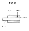
- the worm 309 may be fixed to the shaft 311 by radially forming a threaded hole 309c through the worm 309, and fastening a screw 321 as a fixing member in the threaded hole 309c.
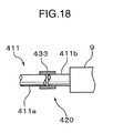
- a torque limiter 420 for protecting a gear and the like against a rotating torque.
- the torque limiter 420 is provided in a driving force transmitting system between a motor 13 and a shaft 11.
- the torque limiter 420 includes a first gear 415a, a second gear 415b, a spring 431 for urging the first gear 415a and the second gear 415b in directions toward each other, and flanges 430a and 430b for absorbing a reaction force of the spring 431.
- the flanges 430a and 430b are mounted on a shaft 430 extending through the first gear 415a and the second gear 415b.
- the first gear 415a and the second gear 415b are mounted between the paired flanges 430a and 430b along with the spring 431 in a compressed state, and are urged toward each other by a resilient force of the spring 431.
- a friction is caused between the first gear 415a and the second gear 415b, and a torque to be transmitted by the stationary frictional force is set to such an amount that does not damage a gear or a like element. If a torque larger than a maximum stationary frictional force is generated, a slip is caused between the first gear 415a and the second gear 415b, and the first gear 415a and the second gear 415b are rotated relative to each other.
- a gear 112 is mounted on the shaft 111.
- the gear 112 is connected to a gear 114 connected to the motor 113 via a gear 115 so that a driving force of the motor 113 is transmittable to the shaft 111.
- the finger mechanism 101 is integrally and pivotally movable with a worm gear 107
- the finger mechanism 103 is integrally and pivotally movable with a worm gear 108.
- the finger mechanism 101 and the finger mechanism 103 are each operable to change the open angle thereof by driving the motor 113.
- the open angles of the finger mechanism 101 and the finger mechanism 103 are respectively changeable depending on the shape or the like of an article to be gripped.
- a pin support portion 102c for supporting a pivot pin 6 is formed on the first palm portion 102a.
- a pivot pin 120 for pivotally supporting the finger mechanism 101 in a gripping direction is mounted on the pin support portion 102c.
- the finger mechanisms 103, 104a, and 104b are each pivotally movable in the gripping direction.
- FIGS. 20A through 20C are diagrams showing a construction of a joint mechanism in accordance with the twelfth embodiment of the invention. Parts with the same reference numerals as in the first embodiment indicate the same parts as in the first embodiment.
- the joint mechanism is operable to change the angle of the first link 1 and the angle of the third link 3 with respect to the second link 2 relative to each other by driving a motor 13.
- the second link 2 is pivotally moved about an axis of a pivot pin 6, with the third link 3 being kept unmoved.
- the pivot angle of the first link 1 with respect to the second link 2 is determined by a force to be applied from the upper body member 4.
- FIG. 20C shows an example, wherein the force to be applied to the third link 3 is larger than the force to be applied to the first link 1.
- the relation between the pivot angles of the first link 1 and the third link 3 is determined depending on the magnitudes of forces to be applied to the first link 1 and the third link 3. Accordingly, providing the braking mechanism described in the fifth embodiment, or the clutch mechanism described in the sixth embodiment in the joint mechanism of the twelfth embodiment enables to positively control the pivot angles of the first link 1 and the third link 3. Thereby, the pivot angles of the first link 1 and the third link 3 can be adjusted to an intended angle, and the joint mechanism is easily set in any posture.
- the connecting member may be constituted of an integrally formed shaft.
- the first worm and the second worm may have helical grooves in opposite directions to each other.
- an arrangement of pivotally moving the first link and the third link in opposite directions to each other by rotating the connecting member can be realized with a simplified arrangement.
- the joint mechanism may further include a motor, fixed to the second link, for rotating the connecting member.
- the joint mechanism may further include centering means for restoring the connecting member to a predetermined position in an axis direction.
- centering means for restoring the connecting member to a predetermined position in an axis direction.
- the centering means may include a resilient member, and the resilient member may be operable to restore the connecting member to the predetermined position by a resilient force of the resilient member.
- the connecting member can be restored to the predetermined position with a simplified arrangement.
- a reduction ratio between the first worm and the first worm wheel may be set larger than a reduction ratio between the second worm and the second worm wheel.
- the first link serving as a base link to be connected to the supporter receives a larger torque from the worm and the worm wheel.
- the joint mechanism may further include resisting means for generating a resistance force depending on a relative moving speed of the connecting member with respect to the second link in the axis direction.
- resisting means for generating a resistance force depending on a relative moving speed of the connecting member with respect to the second link in the axis direction.
- This arrangement is advantageous in suppressing the connecting member from abruptly moving in the axis direction resulting from a change in gravitational force, the weight of the connecting member, or the like, depending on the direction of the second link.
- the arrangement is advantageous in obtaining a stable operation of the joint mechanism when the joint mechanism approaches an article for gripping the article.
- the joint mechanism may further include resisting means for generating a resistance force depending on relative rotational speeds of the first worm wheel and the second worm wheel with respect to the second link. This arrangement enables to suppress the first link and the third link from pivotally and abruptly moving.
- the resisting means may include a viscous member to be provided in a space between the two members subjected to the relative movement.
- the joint mechanism may further include at least one of a braking mechanism for preventing a change in angle of the first link with respect to the second link, and a braking mechanism for preventing a change in angle of the third link with respect to the second link.
- the positions of the first link, the second link, and the third link can be stabilized without a change in angle between the second link, and the first link or the third link.
- the direction of at least one of the first link and the third link can be defined in advance before the joint mechanism performs a predetermined operation such as an operation of gripping an article.
- the arrangement is advantageous in optimally adjusting the posture of the joint mechanism immediately before the joint mechanism performs a predetermined operation.
- the joint mechanism may further include a clutching mechanism for selectively transmitting a driving force on at least one of a driving force transmission path from the motor to the first link, and a driving force transmission path from the motor to the third link.
- the joint mechanism may further include an angle sensor for detecting a relative angle between the first link or the third link having the clutching mechanism, and the second link, wherein the clutching mechanism is operated based on an output of the angle sensor.
- the joint mechanism may further include: multiple gears, between the motor and the connecting member, for transmitting a torque of the motor; and a torque limiter for cutting off transmission of an exceedingly large torque.
- This arrangement enables to prevent damage of a gear for transmitting a driving force from the motor to the connecting member.
- the article can be securely gripped in the adjusted state.
- torques to be applied to the worms via the worm wheels may be unbalanced to each other.
- the worms may be displaced in the axis direction thereof by a distance corresponding to a torque difference between the worm wheels.
- the worms are integrally displaced in the axis direction so that the torques to be applied from the article to the first link and the third link are balanced.
- the worm wheels are rotated in identical directions to each other; or one of the worm wheels whose applied torque is larger is kept unrotated, and the other of the worm wheels is rotated.
- a relation: dA ⁇ dB ⁇ 0 is established when the worms are moved in the axis direction.
- rotating the connecting member depending on the size of an article to be gripped enables to grip various kinds of articles different in size, and eliminate unbalance between the torques to be applied to the first link and the third link resulting from axial movement of the connecting member, depending on the shape of the article or positional relation of the article with respect to the first link and the third link. Accordingly, this arrangement enables to realize a gripping mechanism having degrees of freedom necessary for a gripping operation, with a simplified construction, and capable of gripping an article depending on the shape of the article, without using multiple motors.
- the joint mechanism may further include an angle sensor for detecting a relative angle between the parts, wherein the braking mechanism is operated, using a signal based on an output of the angle sensor.
- Still another aspect of the invention is directed to a joint device including: the aforementioned joint mechanism; and a supporter for supporting the joint mechanism.
- the joint mechanism according to the invention can be utilized as a gripping mechanism corresponding to a hand finger to be used in a robotic manipulator, and a joint mechanism for a robot.
Landscapes
- Engineering & Computer Science (AREA)
- Robotics (AREA)
- Mechanical Engineering (AREA)
- Manipulator (AREA)
- Steering Control In Accordance With Driving Conditions (AREA)
- Seal Device For Vehicle (AREA)
- Spinning Or Twisting Of Yarns (AREA)
- Transmission Devices (AREA)
- Chair Legs, Seat Parts, And Backrests (AREA)
Abstract


Description
- The present invention relates to a joint mechanism, and more particularly relates to a joint mechanism and a joint device primarily for use in a robotic manipulator.
- In recent years, shortage of manpower resulting from a declining birthrate and an aging population, as well as an increase in aging population are concerned, and development of industrial/home-use robots for compensating for these problems is expected. In particular, it is essential and important that robots have a gripping mechanism capable of gripping a variety of kinds of articles, and a joint mechanism capable of setting an intended posture to do a complicated work. Application of the gripping mechanism to a prosthetic hand for persons with hand disabilities has also been investigated in various ways.
- In view of the above circumstances, some finger mechanisms for gripping an article have been proposed.
FIG. 21 shows an example, wherein a finger gripping mechanism incorporated with a worm and a worm wheel is used as a prosthetic hand (see e.g. patent document 1). - Specifically, a
worm wheel 93 is rotated by aworm 92 mounted at a lead end of amotor 91. Thereby,links link 95 is exerted on thelink 95, there is no likelihood that theworm wheel 93 may be rotated in backward direction because of engagement with theworm 92. In this arrangement, the gripping mechanism is allowed to keep holding an article. -
FIG. 22 shows an example of a finger of a gripping mechanism having an increased degree of freedom by using multiple motors (see e.g. patent document 2). In the gripping mechanism, fourmotors 96 through 99 are used to obtain four degrees of freedom. - Patent document 1:
JP (tokuhyo) Hei 9-510128 - Patent document 2:
JP Hei 11-156778 - The conventional gripping mechanism has the following problem. For instance, in the gripping mechanism shown in
FIG. 21 , since the degree of freedom is one, it is difficult to grip articles of various shapes. For instance, thelink 95 serving as a finger does not fit an article of a flat plate-like shape. Accordingly, the gripping mechanism is incapable of gripping the article with a proper frictional force. In other words, in the joint mechanism shown inFIG. 21 , thelink 95 serving as a finger is not set in an intended posture. - On the other hand, the gripping mechanism shown in
FIG. 22 has a sufficient degree of freedom for a gripping operation. However, since the number of the motors in the gripping mechanism is increased, the production cost may be increased. In other words, in the joint mechanism shown inFIG. 22 , the number of drive sources may be increased, although an intended posture is obtained. - In view of the above, it is an object of the present invention to solve the above problem. It is another object of the present invention to realize a joint mechanism capable of setting any intended postures with a simplified arrangement.
- A joint mechanism according to an aspect of the invention includes: a first link; a second link pivotally linked to the first link; a third link pivotally linked to the second link; a connecting member supported on the second link; a first worm and a second worm coupled to each other by the connecting member, the first worm and the second worm each being rotatable about its axis and movable in an axis direction thereof; a first worm wheel in mesh with the first worm to pivotally move the first link with respect to the second link; and a second worm wheel in mesh with the second worm to pivotally move the third link with respect to the second link, wherein the joint mechanism satisfies a relation: dA × dB ≧ 0 by rotation of the first worm and the second worm, and the joint mechanism satisfies a relation: dA × dB ≦ 0 by movement of the first worm and the second worm in the axis direction, where A is an angle defined by the first link and the second link, B is an angle defined by the second link and the third link, dA is a change amount of the angle A, and dB is a change amount of the angle B.
-
-
FIGS. 1A through 1C are diagrams showing a construction of a joint mechanism in accordance with the first embodiment of the invention. -
FIGS. 2A through 2C are diagrams for describing a series of movements of the joint mechanism in accordance with the first embodiment of the invention, in the case a shaft is rotated, with a first link being fixed. -
FIGS. 3A through 3C are diagrams for describing a series of movements of the joint mechanism in accordance with the first embodiment of the invention, in the case where an article to be gripped is in a displaced position. -
FIGS. 4A through 4C are diagrams for describing a series of movements of the joint mechanism in accordance with the first embodiment of the invention, in the case where a small-sized article is to be gripped. -
FIGS. 5A through 5C are diagrams showing a construction of a joint mechanism in accordance with the second embodiment of the invention. -
FIGS. 6A through 6C are diagrams showing a construction of a joint mechanism in accordance with the third embodiment of the invention. -
FIGS. 7A through 7C are diagrams showing a construction of a joint mechanism in accordance with the fourth embodiment of the invention. -
FIGS. 8A and 8B are diagrams showing a construction of a brake mechanism provided in a joint mechanism in accordance with the fifth embodiment of the invention. -
FIGS. 9A through 9C are diagrams showing a construction of the joint mechanism in accordance with the fifth embodiment of the invention. -
FIGS. 10A and 10B are diagrams showing a clutch mechanism and a third link provided in a joint mechanism in accordance with the sixth embodiment of the invention. -
FIGS. 11A through 11C are diagrams showing a construction of the joint mechanism in accordance with the sixth embodiment of the invention. -
FIG. 12 is a diagram showing a gripping device in accordance with the seventh embodiment of the invention. -
FIG. 13 is a diagram showing a modification of the gripping device in accordance with the seventh embodiment of the invention. -
FIG. 14 is a diagram showing a construction of a joint mechanism in accordance with the eighth embodiment of the invention. -
FIG. 15A is a diagram showing a construction of a joint mechanism in accordance with the ninth embodiment of the invention. -
FIG. 15B is a diagram showing fixing means. -
FIG. 16 is a diagram showing a construction of a modification of the joint mechanism in accordance with the ninth embodiment of the invention. -
FIG. 17A is a diagram showing a construction of a joint mechanism in accordance with the tenth embodiment of the invention. -
FIG. 17B is a diagram showing a torque limiter. -
FIG. 18 is a diagram showing a torque limiter to be used in a modification of the tenth embodiment of the invention. -
FIGS. 19A and 19B are diagrams showing a construction of a joint mechanism in accordance with the eleventh embodiment of the invention. -
FIGS. 20A through 20C are diagrams showing a construction of a joint mechanism in accordance with the twelfth embodiment of the invention. -
FIG. 21 is a diagram showing a conventional joint mechanism. -
FIG. 22 is a diagram showing another conventional joint mechanism. - In the following, a best mode for carrying out the invention is described in detail referring to the drawings.
-
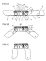
FIGS. 1A through 4C are diagrams showing a joint mechanism embodying the present invention. The joint mechanism of this embodiment is constituted as a gripping mechanism capable of gripping an article. As shown inFIG. 1A , the gripping mechanism includes afirst link 1 as a gripping finger, asecond link 2 as a gripping finger, and athird link 3 as a gripping finger. Thefirst link 1 and thesecond link 2 are pivotally linked to each other about apivot pin 5. Thesecond link 2 and thethird link 3 are pivotally linked to each other about apivot pin 6. Thefirst link 1 is constructed to be connectable to apalm member 4 via apivot pin 4a. The pivot pins 5 and 6 are each fixed to thesecond link 2. Thepivot pin 5 and thepivot pin 6 are provided at longitudinal both ends of thesecond link 2 in parallel to each other. A distal end of thefirst link 1 is linked to a base end of thesecond link 2 via thepivot pin 5, and a distal end of thesecond link 2 is linked to a base end of thethird link 3 via thepivot pin 6. - The gripping mechanism includes two
worm wheels worm wheels worm wheel 7 is pivotally movable about thepivot pin 5, and theworm wheel 8 is pivotally movable about thepivot pin 6. Theworm wheel 7 is fixed to one end of thefirst link 1, and theworm wheel 8 is fixed to one end of thethird link 3. In this construction, thefirst link 1 is integrally rotatable with theworm wheel 7, and thethird link 3 is integrally rotatable with theworm wheel 8. Alternatively, theworm wheel 7 may be integrally formed with thefirst link 1, and theworm wheel 8 may be integrally formed with thethird link 3. - The
worm wheel 7 is meshed with aworm 9, and theworm wheel 8 is meshed with aworm 10. Theworm 9 and theworm 10 are rigidly fixed to ashaft 11, as an example of a connecting member, and are disposed away from each other by a certain distance. Theworms shaft 11. Theworm 9 is a so-called right hand screw, and theworm 10 is a so-called left hand screw. In other words, theworms - A module constituted of the
worm wheel 7 and theworm 9, and a module constituted of theworm wheel 8 and theworm 10 are identical to each other in construction, and the number of teeth and the diameter of the modules are identical to each other. - A
flange 11 a is provided at an intermediate portion of theshaft 11 between theworms gear 12 is rigidly mounted on the intermediate portion of theshaft 11. Theshaft 11 is supported by a pair ofsupport walls second link 2, and extends in the longitudinal direction of thesecond link 2. Thesupport walls shaft 11 is held through the through-holes in such a manner that theflange 11 a is disposed between thesupport walls shaft 11 is rotatable about an axis thereof, and is movable along a translational direction corresponding to an axis direction thereof. - A
spring 16 is mounted between thesupport wall 18 and theflange 11 a, and aspring 17 is mounted between thesupport wall 19 and theflange 11 a, with residual compressive restoring forces of thesprings flange 11a, thesprings support walls worms - A
motor 13 as a drive source is loaded on thesecond link 2. Agear 14 is mounted on a distal end of a drive shaft of themotor 13. Themotor 13 is arranged on the side of theworm wheels shaft 11, and in a space defined by theworm wheels motor 13 is installed in the space, the space can be efficiently utilized, and the gripping mechanism can be constructed with smaller dimensions. Agear 15 is mounted between thegear 14, and agear 12 mounted on theshaft 11. The driving force of themotor 13 is transmitted to theshaft 11 via thegear 14, thegear 15, and thegear 12. Thegear 15 is only allowed to rotate about an axis thereof. But thegear 12 extends in the axis direction of theshaft 11 so that engagement of thegear 12 with thegear 15 is maintained, even if theshaft 11 moves in the translational direction. - An operation to be performed by the gripping mechanism having the above construction is described in the following.
- Let it be assumed that the
first link 1, thesecond link 2, and thethird link 3 are set in a state shown inFIG. 1A , as an initial state. When themotor 13 is driven in this state, thegear 14, thegear 15, and thegear 12 are respectively rotated, and theshaft 11 is rotated in e.g. F direction shown inFIG. 1A . In this state, since thegear 12 and theworms shaft 11, both of theworms - Observing the above operation from the viewpoint of the
second link 2, theworm wheel 7 starts rotating in V direction inFIG. 1B by rotation of theworm 9, thereby rotating thefirst link 1 connected to theworm wheel 7 in V direction. Similarly, thethird link 3 is rotated in W direction inFIG. 1B by rotation of theworm 10. Let it be assumed that, in the case where theshaft 11 is rotated by a certain rotation angle, the angle defined by thefirst link 1 and thesecond link 2 is set to the angle "A", and the angle defined by the second link and the third link is set to the angle "B". Theshaft 11 is then further rotated until the angle "A" and the angle "B" are respectively set to about 90 degrees, as shown inFIG. 1C . - By performing the above series of operations, both of the change amount dA of the angle "A", and the change amount dB of the angle "B" by rotation of the
shaft 11 are increased. On the other hand, if theshaft 11 is rotated in the backward direction, both of the change amount dA and the change amount dB are decreased. In other words, a relation: dA × dB ≧ 0 is established. While the above series of operations are performed, as far as transmission torques at both ends of theshaft 11 are balanced to each other, theshaft 11 is rotated about the axis thereof, without moving in the axis direction thereof. - If the torques of the
worms worm wheels spring shaft 11 may be moved in the axis direction thereof. However, since the centering means 20 is operable to constantly return theshaft 11 to a neutral position, the positions of thefirst link 1 and thethird link 3 are stabilized. - Next,
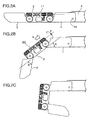
FIGS. 2A through 2C show a series of movements of the first through thethird links 1 through 3, letting it be assumed that thepalm member 4 is defined as a stationary system. Referring toFIG. 2B , assuming that the downward direction on the plane ofFIG. 2B corresponds to the gravitational direction, a gravitational force acts in such a direction as to pivotally move thesecond link 2 counterclockwise. Thereby, theshaft 11 is translationally moved in Q direction with respect to thesecond link 2, with the result that the angle "A" is increased, and the angle "B" is decreased. The centering means 20 has a function of canceling the action of the gravitational force and maintaining the posture of the gripping mechanism. The centering means 20 also has substantially the same function as described above with respect to disturbance such as vibrations. -
FIGS. 3A through 3C are diagrams showing operation states of the gripping mechanism, in the case where an article is to be gripped by the gripping mechanism.FIG. 3A shows substantially the same state as shown inFIG. 1B , wherein the angle "A" nearly equals the angle "B". Now, let it be assumed that as shown inFIG. 3B , anarticle 81 near thefirst link 1 is to be gripped. Since thefirst link 1 is pressed against thearticle 81, thefirst link 1 starts pivotally moving about thepivot pin 5 in such a direction as to decrease the angle "A". Thereby, a translational force is transmitted to theshaft 11 via theworm wheel 7 and theworm 9, and theshaft 11 is moved in P direction against a force of thespring 17 of the centeringmeans 20. Thereby, a rotational driving force is transmitted to thethird link 3 via theworm 10 and theworm wheel 8, with the result that thethird link 3 is rotated in such a direction as to increase the angle "B". Then, theshaft 11 is moved until the unbalance between the torques to be applied to thefirst link 1 and thethird link 3 is eliminated. In this way, even in the case where there is an unbalance between the torques, the unbalance can be eliminated by translationally moving of theworms article 81 as an object to be gripped. In performing the above operation, the change amounts of the angles "A" and "B" by translational movement of theshaft 11 are: dA ≦ 0, dB ≧ 0. In other words, a relation dA × dB ≦ 0 is established concerning the change amounts dA and dB of the angles "A" and "B" by translational movement of theshaft 11. - As shown in
FIG. 3C , theworms shaft 11 are translationally moved in Q direction with respect to anarticle 82 near thethird link 3. Then, a gripping operation is performed while securing a balance in the similar manner as described above. In performing the above operation, the change amounts dA and dB of the angles "A" and "B" by translational movement of theshaft 11 are dA ≧ 0 and dB ≦ 0. In other words, a relation dA × dB ≦ 0 is established concerning the change amounts dA and dB of the angles "A" and "B" by translational movement of theshaft 11. - The
gear 12 extends in the axis direction of theshaft 11. Accordingly, as shown inFIGS. 3B and 3C , an engagement state between thegear 12 and thegear 15 is maintained, even if theshaft 11 is translationally moved in the axis direction. -
FIGS. 4A through 4C show examples, in the case where smaller-sized articles article first link 1 and thethird link 3 in association with translational movement of theshaft 11, whereby the gripping mechanism is allowed to perform a gripping operation. - As described above, in the first embodiment, the size difference or the like of the article can be adjusted by rotating the
shaft 11 including theworms shaft 11. Accordingly, the above arrangement enables to provide a gripping mechanism capable of gripping various kinds of articles different in size or condition. - Specifically, in the first embodiment, if the
shaft 11 is rotated in a step prior to a step of gripping an article, theworm wheels first link 1 and thethird link 3 are changed. In other words, since both of the angle "A" and the angle "B" are increased or decreased, a relation: dA × dB ≧ 0 is established. Accordingly, rotating theshaft 11 depending on the size of an article to be gripped enables to adjust the angle "A" and the angle "B" of thefirst link 1 and thethird link 3 so that the article can be securely gripped. Thereby, the article can be gripped in the adjusted state. On the other hand, in the case where forces to be applied from the article to be gripped to thefirst link 1 and thethird link 3 are unbalanced, because of e.g. positional displacement of the article with respect to thefirst link 1 and thethird link 3, torques to be applied to theworms worm wheels shaft 11 may be displaced in the axis direction thereof by a distance corresponding to the torque difference between theworms worm wheels worm wheels worm wheels first link 1 and thethird link 3. In other words, a relation dA × dB ≦ 0 is established, when theworms worms shaft 11 is moved in the axis direction, while shouldering a reaction force at theworm wheels shaft 11 depending on the size of an article to be gripped enables to grip various kinds of articles different in size, and eliminate unbalance between the torques to be applied to thefirst link 1 and thethird link 3 resulting from axial movement of theshaft 11, depending on the shape of the article or positional relation of the article with respect to thefirst link 1 and thethird link 3. Accordingly, this arrangement enables to realize a gripping mechanism having degrees of freedom necessary for a gripping operation, with a simplified construction, and capable of gripping an article depending on the shape of the article, without using multiple motors. - In the first embodiment, since a connecting member is constructed by the integrally formed
shaft 11, an arrangement capable of obtaining an intended gripping force can be realized with a simplified arrangement. - In the first embodiment, since the
worms first link 1 and thethird link 3 in opposite directions to each other by rotating the shaft. 11 can be realized with a simplified arrangement. - In the first embodiment, since the centering means 20 for restoring the
shaft 11 to the neutral position is provided, the directions of thefirst link 1 and thethird link 3 can be stabilized, while a gripping operation is suspended. Further, since the centering means 20 is operable to restore theshaft 11 to the neutral position by resilient forces of thesprings shaft 11 can be restored to the predetermined position with a simplified arrangement. - In this embodiment, the centering means 20 is provided to maintain a certain shape to be defined by the
first link 1 and thethird link 3 when the gripping mechanism approaches an article for griping the article. Alternatively, as far as high precision is not required in approaching an article, the centering means 20 may be omitted. The modification is advantageous in reducing the cost. - In this embodiment, the
gear 12 is fixed to theshaft 11. Alternatively, thegear 12 may be key-connected to theshaft 11 to allow thegear 12 to move with respect to theshaft 11, while keeping thegear 12 from rotating with respect to theshaft 11. The modification is advantageous in reducing the size of thegear 12, improving the space factor, and avoiding sliding wear on a gear tooth surface. The modification is also advantageous in limiting an area subjected to frictional force to a vicinity of theshaft 11, thereby facilitating translational movement of theshaft 11. - In this section, the second embodiment of the invention is described referring to the drawings.
-
FIGS. 5A through 5C are diagrams showing a joint mechanism in accordance with the second embodiment of the invention. The second embodiment is different from the first embodiment in that aworm wheel 27 and aworm 29 are provided, in place of theworm wheel 7 and theworm 9; but is substantially the same as the first embodiment in other arrangement including the arrangement of the centeringmeans 20. - The
worm wheel 27 and theworm 29, and theworm wheel 8 and theworm 10 are the same in diameter, but theworm wheel 27 and theworm 29 are half in module of theworm wheel 8 and theworm 10. Accordingly, the number of teeth of theworm wheel 27 is twice of the number of teeth of theworm 8, and the reduction ratio of a worm gear constituted of theworm wheel 27 and theworm 29 is twice of the reduction ratio of a worm gear constituted of theworm wheel 8 and theworm 10. - Accordingly, a torque between a
first link 1 and asecond link 2 by rotation of ashaft 11 is twice of a torque between thesecond link 2 and athird link 3. This arrangement corresponds to a general phenomenon that a moment of force at a base end of a structural member is larger than a moment of force at a distal end thereof, in the case where a load is applied to the structural member. - In the following, an operation of the second embodiment is described. Since a schematic operation including an operation of centering means 20 of the second embodiment is identical to that of the first embodiment, merely a different point of the second embodiment from the first embodiment is described.
- As described above, since the reduction ratio of the worm gear at the base end of the joint mechanism is twice of the reduction ratio of the worm gear at the distal end thereof with respect to rotation of the
shaft 11, a portion of the link, close to apalm member 4, is capable of receiving a larger moment of force. Accordingly, a load performance of the joint mechanism in performing a gripping operation is increased. In this arrangement, as shown inFIG. 5B , the angle "A" by rotation of theshaft 11 becomes smaller than the angle "B, and unbalance may occur between thefirst link 1 and thethird link 3. However, the unbalance can be eliminated by translational movement of theshaft 11. - As described above, the second embodiment is advantageous in easily eliminating a difference in generated torque, and easily realizing a joint mechanism capable of receiving a proper moment of force suitable for the structure of the joint mechanism.
- In this embodiment, the reduction ratio is changed by changing the module size. Alternatively, the reduction ratio may be changed by changing the diameter of the worm wheel.
- In this section, the third embodiment of the invention is described referring to the drawings.
-
FIGS. 6A through 6C are diagrams showing a construction of a joint mechanism in accordance with the third embodiment of the invention. In the third embodiment, resisting means is provided, in place of the centering means in the first embodiment. In the third embodiment, aflangless shaft 31 is used. The other arrangement in the third embodiment is substantially the same as the corresponding arrangement in the first embodiment. - The resisting means includes a
sleeve 32 fixed to asecond link 2, and aviscous member 33. Theshaft 31 extends through thesleeve 32. Theviscous member 33 is filled in a space between thesleeve 32 and theshaft 31. A desirable viscosity of theviscous member 33 is a viscosity capable of moving theshaft 31 at a speed equal to or smaller than about 10 mm/sec by the weight of theshaft 31. The material for theviscous member 33 is preferably a gel material or an oil material having a large viscosity. - The
viscous member 33 is a material having a property that a resistance force is generated depending on a relative speed between theshaft 31 and thesleeve 32. Theviscous member 33 is operable to keep theshaft 31 from moving at an unduly large relative speed. - An operation of the third embodiment is described merely on a point different from the first embodiment.
- The
shaft 31 is gradually displaced in the axis direction thereof by the weight thereof, a change in gravitational force, or the like due to the effect of theviscous member 33. Since theshaft 31 is not greatly displaced when the joint mechanism approaches an article for gripping the article, a stable gripping operation can be realized, while suppressing afirst link 1 and athird link 3 from abruptly and pivotally moving. - As shown in
FIGS. 6B and 6C , similarly to the first embodiment, in gripping anarticle viscous member 33 allows gradual displacement of theshaft 31 in P direction or Q direction, as thefirst link 1 and thethird link 3 are contacted with the article. In the third embodiment, there is no need of generating a force against deformation of a spring. - In this section, the fourth embodiment of the invention is described referring to the drawings.
-
FIGS. 7A through 7C are diagrams showing a construction of a joint mechanism in accordance with the fourth embodiment of the invention. In the fourth embodiment, resisting means is provided, in place of the centering means in the first embodiment. The resisting means in the fourth embodiment is different from the resisting means in the third embodiment. In the fourth embodiment, similarly to the third embodiment, aflangless shaft 41 is used. The other arrangement in the fourth embodiment is substantially the same as the corresponding arrangement in the first embodiment. - The resisting means is constituted of a
viscous member 42, which is sealed in a space between apivot pin 5 and aworm wheel 47, and a space between apivot pin 6 and aworm wheel 48. The material for theviscous member 33 in the third embodiment may be used as a material for theviscous member 42. - The
viscous member 42 is operable to generate a resistance force depending on a relative speed between thepivot pin 5 and theworm wheel 47, and a resistance force depending on a relative speed between thepivot pin 6 and theworm wheel 48. This arrangement enables to prevent afirst link 1 and athird link 3 from abruptly and pivotally moving. - The operation of the fourth embodiment is substantially the same as the operation of the third embodiment, as shown in
FIGS. 7B and 7C , and the effect of the fourth embodiment is substantially the same as the effect of the third embodiment. - In the fourth embodiment, the
viscous member 42 is sealed in the space between thepivot pin 5 and theworm wheel 47, and the space between thepivot pin 6 and theworm wheel 48 to form a speed resistive structure for applying a resistance to the speed. The invention is not limited to the above. Alternatively, a viscous member may be sealed in a space between asecond link 2 and theworm wheel 47, and a space between thesecond link 2 and theworm wheel 48. - In the third and the fourth embodiments, a speed resistive structure by the viscous member is employer. Alternatively, a speed resistive structure by a frictional member may be employed, in place of using the viscous member. The speed resistive structure may be constituted of e.g. an annular resin member. The modification is advantageous in obtaining substantially the same effect as described above.
- In the case where a speed resistive function and a restoring force for restoring a normal form are required, the centering means 20 used in the first embodiment may be used in addition to the speed resistive structure.
- In this section, the fifth embodiment of the invention is described referring to the drawings.
-
FIGS. 8A and 8B , andFIGS. 9A through 9C are diagrams showing a construction of a joint mechanism in accordance with the fifth embodiment of the invention. -
FIG. 8A shows abrake mechanism 50 as a braking mechanism. Thebrake mechanism 50 has a solenoid. Specifically, thebrake mechanism 50 includes amagnet 52 made of a magnetic material, apad 51 constituted of an elastic member such as a rubber, and attached to a distal end of themagnet 52, a bottomedcylindrical yoke 54 made of a magnetic material, a ring-like coil 53 provided in theyoke 54, and aspring 55 wound at the other end of themagnet 52 at a position opposite to thepad 51 and inside theyoke 54. -
FIG. 8A shows a de-energized state, wherein thespring 55 has a free length. On the other hand,FIG. 8B shows an energized state, wherein a magnetic flux generated around thecoil 53 is guided along theyoke 54, and themagnet 52 is attracted inwardly against a resilient force of thespring 55 by a magnetic force. -
FIG. 9A shows the entirety of the joint mechanism provided with thebrake mechanism 50. The arrangement of the fifth embodiment is substantially the same as the arrangement of the first embodiment except for thebrake mechanism 50. Thebrake mechanism 50 is loaded on athird link 3, and is normally set in an energized state. The reference numerals 58 and 59 inFIG. 9A each indicates a pivot pin. Africtional plate 57 is rigidly fixed to thepivot pin 59 on thethird link 3. In other words, thefrictional plate 57 is fixed to asecond link 2. - The
frictional plate 57 has an arc-shaped and rough frictional surface, as opposed to thepad 51. When thebrake mechanism 50 is de-energized, themagnet 52 protrudes from thebrake mechanism 50, as shown inFIG. 8A . Thereby, thepad 51 is contacted with the rough frictional surface of thefrictional plate 57, and a large frictional force is generated between thepad 51 and thefrictional plate 57. -
Angle sensors second link 2. Theangle sensor 71 is operable to measure the angle "A" of afirst link 1 with respect to thesecond link 2. Theangle sensor 72 is operable to measure the angle "B" of thethird link 3 with respect to thesecond link 2. Theangle sensors brake mechanism 50 and amotor 13, based on a signal outputted from theangle sensors - The other arrangement of the fifth embodiment is substantially the same as the corresponding arrangement of the first embodiment.
- An operation to be performed by the joint mechanism having the above arrangement is described in the following.
- While the joint mechanism is in the states as shown in
FIGS. 9A and 9B , since thebrake mechanism 50 is energized, thepad 51 is not contacted with thefrictional plate 57. Accordingly, similarly to the first embodiment, thefirst link 1 and thethird link 3 are pivotally moved. As shown inFIG. 9B , when thethird link 3 is pivotally moved by a predetermined angle, the output of theangle sensor 72 becomes equal to a predetermined value. When thebrake mechanism 50 is de-energized in this state, a magnetic field for attracting themagnet 52 is gone. Then, themagnet 52 protrudes from thebrake mechanism 50 by thespring 55, and consequently, thepad 51 is contacted with thefrictional plate 57. Thereby, thethird link 3 is fixed with respect to thesecond link 2. - Further rotating a
shaft 11 in the above state keeps thethird link 3 in the state shown inFIG. 9B , because thethird link 3 is fixed to thesecond link 2. On the other hand, thefirst link 1 is pivotally movable, thefirst link 1 is pivotally moved in such a direction as to increase the angle "A". Since aworm wheel 8 is not rotated in the above state, theshaft 11 is translationally moved in Q direction inFIG. 9B against a spring force of centering means 20 while rotating by rotation of aworm 10. Then, suspending themotor 13 in the state shown inFIG. 9C by monitoring the output of theangle sensor 71 retains the relative angles between the first through thethird links 1 through 3 thereat. - As described above, the fifth embodiment is advantageous in obtaining an intended stationary state of a joint mechanism by providing the
brake mechanism 50, and fixing thethird link 3 with respect to thesecond link 2 so that thethird link 3 is not pivotally rotated relative to thesecond link 2. The fifth embodiment is advantageous in gripping various kinds of articles after the joint mechanism is adjusted to an intended stationary state suitable for gripping the articles. In the fifth embodiment, substantially two degrees of freedom are obtained by using a single motor. - In the fifth embodiment, the
brake mechanism 50 is provided on thethird link 3 to prevent relative movement with respect to thesecond link 2. Alternatively, thebrake mechanism 50 may be mounted on thefirst link 1, and thefrictional plate 57 may be mounted on thepivot pin 58 so that the angle "B" is adjusted after the angle "A" is set. Further alternatively, thebrake mechanism 50 may be loaded on both of thefirst link 1 and thethird link 3. In both of the modifications, it is possible to obtain a stationary gripping state. - The shape of the
frictional plate 57 and the arrangement of thebrake mechanism 50 are not limited to the above. As far as a relative movement between two links can be fixed, various modifications are applicable. Use of a solenoid as an example of thebrake mechanism 50 is advantageous because the size of an actuator can be reduced. In the case where frictional fixation is difficult in the aspect of curability, mechanical fixation may be used. For instance, a certain number of pin holes may be formed in the pivot direction, and a pin may be fixedly inserted in a selected one of the pin holes. In the modification, the fixation is discrete fixation. - In this embodiment, the
angle sensors - As described above, in this embodiment, distributing a driving force from a limited number of motors to plural joints, providing a brake mechanism suitable for the joints, and fixing the joints at an intended position enables to provide substantially a change in degree of freedom by using the limited number of motors.
- In this section, the sixth embodiment of the invention is described referring to the drawings.
-
FIGS. 10A and 10B , andFIGS. 11A through 11C are diagrams showing a construction of a joint mechanism in accordance with the sixth embodiment of the invention. Parts with the same reference numerals as in the first embodiment indicate the same parts as in the first embodiment. -
FIGS. 10A and 10B show athird link 3 and parts to be loaded on thethird link 3 in the sixth embodiment, whereinFIG. 10B is a side view, andFIG. 10A is a plan view. Thereference numeral 61 indicates a clutch mechanism as a clutching mechanism constituted of an electromagnet. Theclutch mechanism 61 is fixed to thethird link 3, and apivot pin 6 is mountable in theclutch mechanism 61.Worm wheels worm wheels worm wheels worm wheels worm wheel 68 is different from theworm wheel 8 in the first embodiment in that theworm wheel 68 is not fixed to thethird link 3.Angle sensors angle sensors - The
clutch mechanism 61 is operable to selectively connect and disconnect a transmission path of a driving force from amotor 13 to thethird link 3 by switching between a connected state and a disconnected state of theworm wheel 68 with respect to thethird link 3. In this embodiment, theclutch mechanism 61 is operable to connect a transmission path of a driving force by a frictional force resulting from a magnetic attraction force. Referring toFIG. 10A , when theclutch mechanism 61 is de-energized, theworm wheel 68 is disengaged from thethird link 3, and accordingly, the driving force of themotor 13 is not transmitted to thethird link 3. In other words, theworm wheel 68 is freely rotatable with respect to thethird link 3. On the other hand, when theclutch mechanism 61 is energized, theworm wheel 68 is magnetically attracted to theclutch mechanism 61, whereby theworm wheel 68 is integrally rotatable with thethird link 3. - Similarly to the fourth embodiment, the
third link 3 and asecond link 2 are viscously linked to each other. The other arrangement of the sixth embodiment is the same as the corresponding arrangement of the first embodiment. - An operation to be performed by the joint mechanism having the above arrangement is described in the following.
- While the joint mechanism is in the states shown in
FIGS. 11A and 11B , since theclutch mechanism 61 is energized, theworm wheel 68 is integrally rotatable with thethird link 3. Accordingly, similarly to the first embodiment, thefirst link 1 and thethird link 3 are pivotally moved in association with rotation of ashaft 11. Referring toFIG. 11B , when theclutch mechanism 61 is de-energized at a point of time when the output of theangle sensor 72 becomes equal to a predetermined value, theworm wheel 68 is disengaged from thethird link 3, and accordingly, theworm wheel 68 is freely rotatable. - When the
shaft 11 is further rotated in the above state, solely theworm wheel 68 is freely rotated in W direction, with thethird link 3 being unmoved, because thethird link 3 is viscously linked to thesecond link 2, and theworm wheel 68 is freely rotatable. Accordingly, thethird link 3 holds the state shown inFIG. 11B . On the other hand, since thefirst link 1 is pivotally movable in association with rotation of theshaft 11, thefirst link 1 is pivotally moved in such a direction as to increase the angle "A". When themotor 13 is suspended in the state ofFIG. 11C by monitoring the output of e.g. theangle sensor 71, and theclutch mechanism 61 is energized, the relative angles between the first through thethird links 1 through 3 are retained thereat. - As described above, the sixth embodiment is advantageous in preventing relative rotation between the
third link 3 and thesecond link 2 by theclutch mechanism 61. Similarly to the fifth embodiment, the sixth embodiment is advantageous in obtaining an intended stationary state of the joint mechanism. The sixth embodiment is advantageous in gripping various kinds of articles, after the joint mechanism is adjusted to an intended stationary state suitable for gripping the articles. - Similarly to the fifth embodiment, the clutch mechanism may be loaded on the
first link 1, or loaded on both of thefirst link 1 and thethird link 3. - In the sixth embodiment, the
clutch mechanism 61 using an electromagnet is used as a mechanism for connecting theworm wheel 68 and thethird link 3. The invention is not limited to the above. As far as a modification does not depart from the scope of the invention, any modification is applicable as necessary. - In the sixth embodiment, similarly to the fifth embodiment, distributing a driving force from a limited number of motors to plural joints, providing a clutch mechanism suitable for the joints, and fixing the joints at an intended position enables to provide substantially a change in degree of freedom by using the limited number of motors.
- In the first through the sixth embodiments, the joint mechanisms have been described as examples of a gripping mechanism. The invention is not limited to the above. In other words, the invention may be applicable to a joint mechanism having a purpose of use other than the above, in place of a link mechanism for gripping an article.
- A gripping device operable to grip multitudes of kinds of articles can be easily realized at a low cost by applying the joint mechanisms described in the first through the sixth embodiments, as a gripping finger of a gripping device as an embodiment of a joint device. For instance,
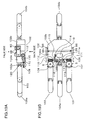
FIG. 12 shows an example of a gripping device incorporated with a single joint mechanism.FIG. 13 shows an example of a gripping device incorporated with multiple joint mechanisms. - The gripping device shown in
FIG. 12 is a single-fingered gripping device, wherein a palm member is provided as opposed to the gripping finger. Ajoint mechanism 101 is a joint mechanism constructed as the gripping mechanism described in the first embodiment. Afirst link 1 of thejoint mechanism 101 is connected to apalm member 73 by apivot pin 73a. Thejoint mechanism 101 is supported on thepalm member 73 as a supporter. Thepalm member 73 is connected to awrist member 74. Thejoint mechanism 101 is pivotally moved about an axis of thepivot pin 73a of thepalm member 73 by a motor (not shown) built in thepalm member 73. Ashaft 11 is rotated about an axis thereof and is displaced in an axis direction thereof by driving amotor 13. Thereby, thefirst link 1 and athird link 3 are allowed to grip anarticle 85 along the shape of thearticle 85. Thus, a gripping operation is performed. Alternatively, thefirst link 1 and thepalm member 73 may be integrally constructed, in place of connecting thefirst link 1 and thepalm member 73 by a pin. In the modification, the integrally formed unit serves as a first link, and the first link is supported on thewrist member 74 serving as a supporter. -
FIG. 13 shows a two-fingered gripping device.Joint mechanisms first link 1 of thejoint mechanism 102 is connected to apalm member 75 by apivot pin 75a, and afirst link 1 of thejoint mechanism 103 is connected to thepalm member 75 by apivot pin 75b. Thepalm member 75 is connected to awrist member 76. Alternatively, thepalm member 75 and thewrist member 76 may be integrally constructed. Thepalm member 75 and thewrist member 76 serve as a supporter. Thejoint mechanisms palm member 75. Similarly to the single-fingered gripping device, thefirst link 1 and athird link 3 are allowed to grip thearticle 85 along the shape of thearticle 85 by rotations and axial movements of ashaft 11 in thejoint mechanism 102 and ashaft 11 in thejoint mechanism 103. Thus, a gripping operation is performed. - Alternatively, the
first link 1 of thejoint mechanism 102 and thepalm member 75 may be integrally constructed. In the modification, the integrally constructed and bent-shaped unit serves as a first link, the first link is supported on thewrist member 76 serving as a supporter, and thefirst link 1 of thejoint mechanism 103 is linked to the first link. Further alternatively, thefirst link 1 of thejoint mechanism 103 and thepalm member 75 may be integrally constructed. - Further alternatively, the
first link 1 of thejoint mechanism 102, thefirst link 1 of thejoint mechanism 103, and thepalm member 75 may be integrally constructed. In the modification, the integrally constructed unit serves as a first link, and the first link is supported on thewrist member 76 serving as a supporter. In other words, in this arrangement, the first link is used in common between the twojoint mechanisms - The
palm member 75 may be loaded with a mechanism substantially equivalent to a joint mechanism. Further alternatively, any one of the second through the sixth embodiments may be used as a joint mechanism, Further alternatively, a gripping device, wherein joint mechanisms are arranged in parallel to each other, may be constructed. The modification is advantageous in increasing the gripping force. Further alternatively, a robot or a like device incorporated with the gripping device may be realized. - In this section, the eighth embodiment of the invention is described referring to the drawings.
-
FIG. 14 is a diagram showing a construction of a joint mechanism in accordance with the eighth embodiment of the invention. Parts with the same reference numerals as in the first embodiment indicate the same parts as in the first embodiment. - In the eighth embodiment, a
gear 212 mounted on ashaft 11 is arranged on the outside of aworm 9. Specifically, whereas in the first embodiment, thegear 12 is mounted between the pairedworms shaft 11, in the eighth embodiment, theworm 9 is disposed at an intermediate portion of theshaft 11, and thegear 212 is disposed on the outside of theworm 9. Accordingly, aworm wheel 7 on afirst link 1 is disposed at a position slightly closer to a middle portion of asecond link 2, in place of being disposed at one end of thesecond link 2. In the eighth embodiment having the above arrangement, as compared with the first embodiment, the distance between theworm wheels first link 1 and athird link 3 can be reduced. - In this section, the ninth embodiment of the invention is described referring to the drawings.
-
FIGS. 15A and 15B are diagrams showing a construction of a joint mechanism in accordance with the ninth embodiment of the invention. Parts with the same reference numerals as in the first embodiment indicate the same parts as in the first embodiment. - In the ninth embodiment, a
worm 309 is rotatably mounted on ashaft 311, and fixing means for fixing theworm 309 to theshaft 311 is provided. Similarly to the first embodiment, aworm 10 is fixed to theshaft 311. An example is described in the following. - An
insertion hole 309b for receiving theshaft 311 is formed in theworm 309. Theshaft 311 is received in theinsertion hole 309b. In this arrangement, theworm 309 is rotatable relative to theshaft 311 about an axis of theshaft 311 in a state that theworm 309 is not fixed by a key 320 to be described later. - The fixing means includes a
worm groove portion 309a, as a key groove formed in theinsertion hole 309b of theworm 309, ashaft groove portion 311a as a key groove formed in theshaft 311, and the key 320 as a fixing member to be inserted in thegroove portions - The
worm groove portion 309a is formed in plural number at a predetermined interval along the circumferential direction of theinsertion hole 309b. In the example shown inFIG. 15B , fourworm groove portions 309a are equidistantly formed. On the other hand, oneshaft groove portion 311 a is formed in an outer surface at one end of theshaft 311 on the side of theworm 309. - The key 320 is engageable in a space defined by the
worm groove portion 309a and theshaft groove portion 311 a. Mounting the key 320 in the space keeps theworm 309 from rotating about the axis of theshaft 311. In other words, the relative angle between theworm 309 and theshaft 311 is fixed. - Mounting the
worm 309 to be rotatable relative to theshaft 311 in assembling afirst link 1 and asecond link 2 makes it possible to freely and pivotally move thefirst link 1 engaged with theworm 309 about an axis of apivot pin 5. Accordingly, the open angle "A" of thefirst link 1 in association with athird link 3 can be finely adjusted. Inserting the key 320 at such a position that one of theworm groove portions 309a matches with theshaft groove portion 311a, with the open angle "A" closest to a predetermined angle, enables to fix theworm 309. InFIG. 15A , thebroken lines 1a and 1b indicate that the initial position of thefirst link 1 is changed by changing theworm groove portion 309a to be selected. The change amount of the open angle "A" of thefirst link 1 at the initial position is determined by the pitch of theworm 309, the number of teeth of theworm wheel 7, and the interval of theworm groove portions 309a. Accordingly, the number of theworm groove portions 309a may be optionally set. - In the ninth embodiment, in mounting the
worm 309 on theshaft 311, theworm 309 can be fixed by mounting theworm 309 in a predetermined direction with respect to theshaft 311, and adjusting the open angles of thefirst link 1 and thethird link 3. - The fixing means is not limited to the arrangement constituted of a key and a key groove. For instance, a worm may be rotatably mounted on a shaft, and the worm may be fixed to the shaft by an adhesive agent. Further alternatively, as shown in
FIG. 16 , theworm 309 may be fixed to theshaft 311 by radially forming a threadedhole 309c through theworm 309, and fastening ascrew 321 as a fixing member in the threadedhole 309c. - In this section, the tenth embodiment of the invention is described referring to the drawings.
-
FIGS. 17A and 17B are diagrams showing a construction of a joint mechanism in accordance with the tenth embodiment of the invention. Parts with the same reference numerals as in the first embodiment indicate the same parts as in the first embodiment. - In the tenth embodiment, a
torque limiter 420 for protecting a gear and the like against a rotating torque is provided. Thetorque limiter 420 is provided in a driving force transmitting system between amotor 13 and ashaft 11. Thetorque limiter 420 includes afirst gear 415a, asecond gear 415b, aspring 431 for urging thefirst gear 415a and thesecond gear 415b in directions toward each other, andflanges spring 431. Theflanges shaft 430 extending through thefirst gear 415a and thesecond gear 415b. - The
first gear 415a is meshed with agear 14 mounted on a drive shaft of themotor 13, and thesecond gear 415b is meshed with agear 12 mounted on theshaft 11. Thefirst gear 415a and thesecond gear 415b are coaxially arranged. - The
first gear 415a and thesecond gear 415b are mounted between the pairedflanges spring 431 in a compressed state, and are urged toward each other by a resilient force of thespring 431. A friction is caused between thefirst gear 415a and thesecond gear 415b, and a torque to be transmitted by the stationary frictional force is set to such an amount that does not damage a gear or a like element. If a torque larger than a maximum stationary frictional force is generated, a slip is caused between thefirst gear 415a and thesecond gear 415b, and thefirst gear 415a and thesecond gear 415b are rotated relative to each other. - The
gear 14 integrally mounted on the output shaft of themotor 13 is meshed with thefirst gear 415a, and a torque is transmitted by frictional contact of thefirst gear 415a and thesecond gear 415b. The torque is then transmitted to thegear 12 mounted on theshaft 11. In the case where rotation of theshaft 11 is suspended resulting from an anomaly operation, a large torque may be exerted on the transmitting system from themotor 13 to theshaft 11. However, since a slip is caused between thefirst gear 415a and thesecond gear 415b with a force equal to or smaller than a limit torque so as not to damage a gear or a like element, there is no likelihood that the gear or the like element may be damaged. - The arrangement of the
torque limiter 420 is not limited to the arrangement of cutting off torque transmission between thefirst gear 415a and thesecond gear 415b. For instance, as shown inFIG. 18 , thetorque limiter 420 may be provided on ashaft 411. Specifically, theshaft 411 is divided into afirst shaft portion 411 a on which agear 12 is mounted, and asecond shaft portion 411b on which aworm 9 is mounted, and a connectingportion 433 is bridgingly formed between thefirst shaft portion 411a and thesecond shaft portion 411b. In this arrangement, a torque is transmitted by friction between the connectingportion 433 and thefirst shaft portion 411a, and between the connectingportion 433 and thesecond shaft portion 411b. In the case where a torque equal to or larger than a limit torque is exerted, a slip is caused between the connectingportion 433 and thefirst shaft portion 411a, and between the connectingportion 433 and thesecond shaft portion 411b. - The arrangement of the torque limiter is not limited to the one utilizing friction. For instance, a surface of the
first gear 415a facing thesecond gear 415b may be formed into a sawtooth shape, and a surface of thesecond gear 415b facing thefirst gear 415a may be formed into a sawtooth shape so that thefirst gear 415a and thesecond gear 415b are meshed with each other. Then, a potential force at which the gear is mounted over the ridge of the sawtooth of the counterpart gear may be set as a limit torque. Similarly to the arrangement utilizing friction, in the above modification, the torque limiter is non-linearly operated with respect to an increase in torque. - In this section, the eleventh embodiment of the invention is described referring to the drawings.
-
FIGS. 19A and 19B are diagrams showing a construction of a joint mechanism in accordance with the eleventh embodiment of the invention. Parts with the same reference numerals as in the first embodiment indicate the same parts as in the first embodiment. - The eleventh embodiment is directed to a joint mechanism functioning as an openable/closable joint of a finger mechanism for a robot hand. A first link of the joint mechanism is a
finger mechanism 101 corresponding to a ring finger, a third link of the joint mechanism is afinger mechanism 103 corresponding to an index finger, and a second link of the joint mechanism is apalm mechanism 102 corresponding to a hand palm. Thepalm mechanism 102 has afirst palm portion 102a, asecond palm portion 102b, and apivot arm 85 and agear 86 for interconnecting thefirst palm portion 102a and thesecond palm portion 102b. The connecting angle between thefirst palm portion 102a and thesecond palm portion 102b is set variable. Thefirst palm portion 102a has afinger mechanism 104a corresponding to a middle finger, and thesecond palm portion 102b has afinger mechanism 104b corresponding to a thumb. - A
motor 113, andsupport walls first palm portion 102a of thepalm mechanism 102.Springs flange 111a of ashaft 111 is mounted between thesprings flange 111a, thesprings support walls worms - A
gear 112 is mounted on theshaft 111. Thegear 112 is connected to agear 114 connected to themotor 113 via agear 115 so that a driving force of themotor 113 is transmittable to theshaft 111. Thefinger mechanism 101 is integrally and pivotally movable with aworm gear 107, and thefinger mechanism 103 is integrally and pivotally movable with aworm gear 108. In this arrangement, thefinger mechanism 101 and thefinger mechanism 103 are each operable to change the open angle thereof by driving themotor 113. The open angles of thefinger mechanism 101 and thefinger mechanism 103 are respectively changeable depending on the shape or the like of an article to be gripped. - A
pin support portion 102c for supporting apivot pin 6 is formed on thefirst palm portion 102a. Apivot pin 120 for pivotally supporting thefinger mechanism 101 in a gripping direction is mounted on thepin support portion 102c. Similarly to thefinger mechanism 101, thefinger mechanisms - In this section, the eleventh embodiment of the invention is described referring to the drawings.
-
FIGS. 20A through 20C are diagrams showing a construction of a joint mechanism in accordance with the twelfth embodiment of the invention. Parts with the same reference numerals as in the first embodiment indicate the same parts as in the first embodiment. - In the first through the sixth embodiments, and the eighth through the tenth embodiments, the joint mechanisms as a gripping mechanism have been described. The twelfth embodiment is directed to a joint mechanism with two joints and adapted to be set in any posture, in place of a joint mechanism for gripping an article. For instance, the joint mechanism of the twelfth embodiment functions as a leg joint of a robot. A
third link 3 of the joint mechanism corresponds to a foot of a robot. Afirst link 1 of the joint mechanism is a link corresponding to e.g. a thigh of a robot. Thefirst link 1 is pin-connected to amember 4 corresponding to an upper body of a robot via apin 4a. Asecond link 2 corresponds to e.g. a lower thigh of the robot's leg. - The joint mechanism is operable to change the angle of the
first link 1 and the angle of thethird link 3 with respect to thesecond link 2 relative to each other by driving amotor 13. In the case where thethird link 3 is contacted with a floor surface, thesecond link 2 is pivotally moved about an axis of apivot pin 6, with thethird link 3 being kept unmoved. On the other hand, the pivot angle of thefirst link 1 with respect to thesecond link 2 is determined by a force to be applied from theupper body member 4. In other words, as described in the first embodiment, if an external force to be applied to thefirst link 1, and an external force to be applied to thethird link 3 are equal to each other, thefirst link 1 and thethird link 3 are rotated, with theshaft 11 being kept unmoved in the axis direction thereof. Accordingly, the pivot angle of thefirst link 1 with respect to thesecond link 2, and the pivot angle of thethird link 3 with respect to thesecond link 2 are made equal to each other (seeFIG. 20B ). On the other hand, if an external force to be applied to thefirst link 1, and an external force to be applied to thethird link 3 are different from each other, theshaft 11 is displaced in the axis direction depending on the force difference, and the pivot angle of thefirst link 1 with respect to thesecond link 2, and the pivot angle of thethird link 3 with respect to thesecond link 2 are made different from each other.FIG. 20C shows an example, wherein the force to be applied to thethird link 3 is larger than the force to be applied to thefirst link 1. - In the twelfth embodiment, the relation between the pivot angles of the
first link 1 and thethird link 3 is determined depending on the magnitudes of forces to be applied to thefirst link 1 and thethird link 3. Accordingly, providing the braking mechanism described in the fifth embodiment, or the clutch mechanism described in the sixth embodiment in the joint mechanism of the twelfth embodiment enables to positively control the pivot angles of thefirst link 1 and thethird link 3. Thereby, the pivot angles of thefirst link 1 and thethird link 3 can be adjusted to an intended angle, and the joint mechanism is easily set in any posture. - In this section, a summary of the embodiments is described.
- (1) As described above, according to the embodiments, if the two worms are rotated in identical directions to each other while an external force is not applied to the first link and the third link, the two worm wheels are rotated in opposite directions to each other, thereby changing the open angles of the first link and the third link. In other words, both of the angle "A" to be defined by the first link and the second link, and the angle "B" to be defined by the second link and the third link are increased or decreased. As a result, a relation: dA × dB ≧ 0 is established. Accordingly, the angles of the first link and the third link can be adjusted depending on rotations of the first worm and the second worm. On the other hand, in the case where an external force to be applied to the first link and an external force to be applied to the third link are unbalanced, torques to be applied to the two worms via the worm wheels may be unbalanced to each other. As a result, the two worms are displaced in the axis direction by a distance corresponding to the torque difference between the worm wheels. Then, the two worms are integrally displaced in the axis direction in such a manner that the torques to be applied to the first link and the third link are balanced. As a result, the two worm wheels are rotated in identical directions to each other, or one of the worm wheels whose applied torque is larger is kept unrotated and the other of the worm wheels is rotated. In other words, a relation: dA × dB ≦ 0 is established when the worms are moved in the axis direction. In this way, in the embodiments, the open angles of the first link and the third link can be changed depending on rotation amounts of the worms. Further, the connecting member is constructed to be movable in the axis direction. Thereby, the angle of the first link or the third link with respect to the second link can be changed. Thus, the embodiments are advantageous in realizing a joint mechanism settable in any posture with a simplified arrangement.
- (2) Preferably, the connecting member may be constituted of an integrally formed shaft.
- (3) Preferably, the first worm and the second worm may have helical grooves in opposite directions to each other. In this arrangement, an arrangement of pivotally moving the first link and the third link in opposite directions to each other by rotating the connecting member can be realized with a simplified arrangement.
- (4) Preferably, the joint mechanism may further include a motor, fixed to the second link, for rotating the connecting member.
- (5) Preferably, the joint mechanism may further include centering means for restoring the connecting member to a predetermined position in an axis direction. In this arrangement, when an external force is not applied to the first link and the third link, the directions of the first link and the third link can be stabilized.
- (6) Preferably, in the above arrangement, the centering means may include a resilient member, and the resilient member may be operable to restore the connecting member to the predetermined position by a resilient force of the resilient member. In this arrangement, the connecting member can be restored to the predetermined position with a simplified arrangement.
- (7) In the case where the first link is constructed to be connectable to a supporter, preferably, a reduction ratio between the first worm and the first worm wheel may be set larger than a reduction ratio between the second worm and the second worm wheel. The first link serving as a base link to be connected to the supporter receives a larger torque from the worm and the worm wheel. In this arrangement, however, since the reduction ratio of the worm gear at the base link is set larger than the reduction ratio between the worm and the worm wheel at a distal link, the joint mechanism is easily controlled depending on the difference in torque.
- (8) Preferably, the joint mechanism may further include resisting means for generating a resistance force depending on a relative moving speed of the connecting member with respect to the second link in the axis direction. This arrangement is advantageous in suppressing the connecting member from abruptly moving in the axis direction resulting from a change in gravitational force, the weight of the connecting member, or the like, depending on the direction of the second link. Thus, the arrangement is advantageous in obtaining a stable operation of the joint mechanism when the joint mechanism approaches an article for gripping the article.
- (9) Preferably, the joint mechanism may further include resisting means for generating a resistance force depending on relative rotational speeds of the first worm wheel and the second worm wheel with respect to the second link. This arrangement enables to suppress the first link and the third link from pivotally and abruptly moving.
- (10) Preferably, the resisting means may include a viscous member to be provided in a space between the two members subjected to the relative movement.
- (11) Preferably, the joint mechanism may further include at least one of a braking mechanism for preventing a change in angle of the first link with respect to the second link, and a braking mechanism for preventing a change in angle of the third link with respect to the second link. In this arrangement, the positions of the first link, the second link, and the third link can be stabilized without a change in angle between the second link, and the first link or the third link. Accordingly, the direction of at least one of the first link and the third link can be defined in advance before the joint mechanism performs a predetermined operation such as an operation of gripping an article. Thus, the arrangement is advantageous in optimally adjusting the posture of the joint mechanism immediately before the joint mechanism performs a predetermined operation.
- (12) In the above arrangement, preferably, the joint mechanism may further include an angle sensor for detecting a relative angle between the links, one of which has the braking mechanism, wherein the braking mechanism is operated based on an output of the angle sensor. This arrangement enables to precisely control the angle of the link.
- (13) Preferably, the joint mechanism may further include at least one of a clutching mechanism for switching between a connected state and a disconnected state of the first worm wheel with respect to the first link, and a clutching mechanism for switching between a connected state and a disconnected state of the second worm wheel with respect to the third link. In this arrangement, the positions of the first link, the second link, and the third link can be stabilized without a change in angle between the second link, and the first link or the third link. Accordingly, the direction of at least one of the first link and the third link can be defined in advance before the joint mechanism performs a predetermined operation such as an operation of gripping an article. Thus, the arrangement is advantageous in optimally adjusting the posture of the joint mechanism immediately before the joint mechanism performs a predetermined operation.
- (14) Preferably, the joint mechanism may further include a clutching mechanism for selectively transmitting a driving force on at least one of a driving force transmission path from the motor to the first link, and a driving force transmission path from the motor to the third link.
- (15) Preferably, the joint mechanism may further include an angle sensor for detecting a relative angle between the first link or the third link having the clutching mechanism, and the second link, wherein the clutching mechanism is operated based on an output of the angle sensor.
- (16) Preferably, the joint mechanism may further include: multiple gears, between the motor and the connecting member, for transmitting a torque of the motor; and a torque limiter for cutting off transmission of an exceedingly large torque. This arrangement enables to prevent damage of a gear for transmitting a driving force from the motor to the connecting member.
- (17) The joint mechanism may be constructed as a gripping mechanism capable of gripping an article. In this arrangement, if the two worms are rotated in identical directions to each other while an external force is not exerted from an article to be gripped on the first link and the third link, the two worm wheels are rotated in opposite directions to each other, thereby changing the open angles of the first link and the third link. In other words, both of the angle "A" and the angle "B" are increased or decreased. As a result, a relation: dA × dB ≧ 0 is established. Accordingly, rotating the connecting member depending on the size of an article to be gripped enables to adjust the angles of the first link and the third link so that the article can be gripped. Thereby, the article can be securely gripped in the adjusted state. On the other hand, in the case where forces to be applied from the article to be gripped to the first link or the third link is unbalanced, because of e.g. positional displacement of the article with respect to the first link and the third link, torques to be applied to the worms via the worm wheels may be unbalanced to each other. As a result, the worms may be displaced in the axis direction thereof by a distance corresponding to a torque difference between the worm wheels. In this arrangement, the worms are integrally displaced in the axis direction so that the torques to be applied from the article to the first link and the third link are balanced. Accordingly, the worm wheels are rotated in identical directions to each other; or one of the worm wheels whose applied torque is larger is kept unrotated, and the other of the worm wheels is rotated. In other words, a relation: dA × dB ≦ 0 is established when the worms are moved in the axis direction. Thereby, a gripping operation can be smoothly performed, even if the article is located in a displaced position. In this way, according to the invention, rotating the connecting member depending on the size of an article to be gripped enables to grip various kinds of articles different in size, and eliminate unbalance between the torques to be applied to the first link and the third link resulting from axial movement of the connecting member, depending on the shape of the article or positional relation of the article with respect to the first link and the third link. Accordingly, this arrangement enables to realize a gripping mechanism having degrees of freedom necessary for a gripping operation, with a simplified construction, and capable of gripping an article depending on the shape of the article, without using multiple motors.
- (18) Preferably, at least one of the first worm and the second worm may be rotatably mounted on the shaft, and the joint mechanism may further include fixing means for fixing the rotatable worm at a predetermined angle with respect to the shaft. In this arrangement, the first worm and the second worm can be easily mounted on the shaft in an intended direction in mounting the first worm and the second worm on the shaft.
- (19) Another aspect of the invention is directed to a joint mechanism including: a single mechanism drive source; a transmission system including three or more parts, the parts being connected to each other at multiple joints, the transmission system being operable to distribute a driving force from the mechanism drive source to the parts; and a braking mechanism for preventing at least one indirect movement of the joints. In this aspect, since the multiple parts are driven by the single mechanism drive source, the joint mechanism can be produced with a simplified structure and with the degrees of freedom necessary for a gripping operation. Further, the degrees of freedom can be changed depending on an operation of the braking mechanism.
- (20) Preferably, the joint mechanism may further include an angle sensor for detecting a relative angle between the parts, wherein the braking mechanism is operated, using a signal based on an output of the angle sensor.
- (21) Yet another aspect of the invention is directed to a joint mechanism including: a single mechanism drive source; a transmission system including three or more parts, the parts being connected to each other at multiple joints, the transmission system being operable to distribute a driving force from the mechanism drive source to the parts; and a clutching mechanism for switching between transmission and non-transmission of the driving force to be distributed by the transmission system. In this aspect, since the multiple parts are driven by the single mechanism drive source, the joint mechanism can be produced with a simplified structure and with the degrees of freedom necessary for a gripping operation. Further, the degrees of freedom can be changed depending on an operation of the clutching mechanism.
- (22) Preferably, the joint mechanism may further include an angle sensor for detecting a relative angle between the parts, wherein the clutching mechanism is operated, using a signal based on an output of the angle sensor.
- (23) Still another aspect of the invention is directed to a joint device including: the aforementioned joint mechanism; and a supporter for supporting the joint mechanism.
- As described above, according to the invention, a joint mechanism settable in any posture can be realized with a simplified arrangement.
- The joint mechanism according to the invention can be utilized as a gripping mechanism corresponding to a hand finger to be used in a robotic manipulator, and a joint mechanism for a robot.
Claims (23)
- A joint mechanism, comprising:a first link;a second link pivotally linked to the first link;a third link pivotally linked to the second link;a connecting member supported on the second link;a first worm and a second worm coupled to each other by the connecting member, the first worm and the second worm each being rotatable about its axis and movable in an axis direction thereof;a first worm wheel in mesh with the first worm to pivotally move the first link with respect to the second link; anda second worm wheel in mesh with the second worm to pivotally move the third link with respect to the second link, whereinthe joint mechanism satisfies a relation: dA × dB ≧ 0 by rotation of the first worm and the second worm, andthe joint mechanism satisfies a relation: dA × dB ≦ 0 by movement of the first worm and the second worm in the axis direction,where A is an angle defined by the first link and the second link, B is an angle defined by the second link and the third link, dA is a change amount of the angle A, and dB is a change amount of the angle B.
- The joint mechanism according to claim 1, wherein
the connecting member is constituted of an integrally formed shaft. - The joint mechanism according to claim 1, wherein
the first worm and the second worm have helical grooves in opposite directions to each other. - The joint mechanism according to claim 1, further comprising
a motor, fixed to the second link, for rotating the connecting member. - The joint mechanism according to claim 1, further comprising
centering means for restoring the connecting member to a predetermined position in the axis direction. - The joint mechanism according to claim 5, wherein
the centering means includes a resilient member, and
the resilient member is operable to restore the connecting member to the predetermined position by a resilient force of the resilient member. - The joint mechanism according to claim 1, wherein
the first link is constructed to be connectable to a supporter, and
a reduction ratio between the first worm and the first worm wheel is set larger than a reduction ratio between the second worm and the second worm wheel. - The joint mechanism according to claim 1, further comprising
resisting means for generating a resistance force depending on a relative moving speed of the connecting member with respect to the second link in the axis direction. - The joint mechanism according to claim 1, further comprising
resisting means for generating a resistance force depending on relative rotational speeds of the first worm wheel and the second worm wheel with respect to the second link. - The joint mechanism according to claim 8 or 9, wherein
the resisting means includes a viscous member to be provided in a space between the two members subjected to the relative movement. - The joint mechanism according to claim 1, further comprising
at least one of a braking mechanism for preventing a change in angle of the first link with respect to the second link, and a braking mechanism for preventing a change in angle of the third link with respect to the second link. - The joint mechanism according to claim 11, further comprising
an angle sensor for detecting a relative angle between the links, one of which has the braking mechanism, wherein
the braking mechanism is operated based on an output of the angle sensor. - The joint mechanism according to claim 1, further comprising
at least one of a clutching mechanism for switching between a connected state and a disconnected state of the first worm wheel with respect to the first link, and a clutching mechanism for switching between a connected state and a disconnected state of the second worm wheel with respect to the third link. - The joint mechanism according to claim 4, further comprising
a clutching mechanism for selectively transmitting a driving force on at least one of a driving force transmission path from the motor to the first link, and a driving force transmission path from the motor to the third link. - The joint mechanism according to claim 13 or 14, further comprising
an angle sensor for detecting a relative angle between the first link or the third link having the clutching mechanism, and the second link, wherein
the clutching mechanism is operated based on an output of the angle sensor. - The joint mechanism according to claim 4, further comprising:multiple gears, between the motor and the connecting member, for transmitting a torque of the motor; anda torque limiter for cutting off transmission of an exceedingly large torque.
- The joint mechanism according to claim 1, wherein
the joint mechanism is constructed as a gripping mechanism capable of gripping an article. - The joint mechanism according to claim 2, wherein
at least one of the first worm and the second worm is rotatably mounted on the shaft, and
the joint mechanism further includes fixing means for fixing the rotatable worm at a predetermined angle with respect to the shaft. - A joint mechanism, comprising:a single mechanism drive source;a transmission system including three or more parts, the parts being connected to each other at multiple joints, the transmission system being operable to distribute a driving force from the mechanism drive source to the parts; anda braking mechanism for preventing at least one indirect movement of the joints.
- The joint mechanism according to claim 19, further comprising
an angle sensor for detecting a relative angle between the parts, wherein
the braking mechanism is operated, using a signal based on an output of the angle sensor. - A joint mechanism, comprising:a single mechanism drive source;a transmission system including three or more parts, the parts being connected to each other at multiple joints, the transmission system being operable to distribute a driving force from the mechanism drive source to the parts; anda clutching mechanism for switching between transmission and non-transmission of the driving force to be distributed by the transmission system.
- The joint mechanism according to claim 21, further comprising
an angle sensor for detecting a relative angle between the parts, wherein
the clutching mechanism is operated, using a signal based on an output of the angle sensor. - A joint device, comprising:the joint mechanism of any one of claims 1 through 22; anda supporter for supporting the joint mechanism.
Applications Claiming Priority (2)
| Application Number | Priority Date | Filing Date | Title |
|---|---|---|---|
| JP2006330629 | 2006-12-07 | ||
| PCT/JP2007/073671 WO2008069306A1 (en) | 2006-12-07 | 2007-12-07 | Joint mechanism and joint device |
Publications (3)
| Publication Number | Publication Date |
|---|---|
| EP2093027A1 true EP2093027A1 (en) | 2009-08-26 |
| EP2093027A4 EP2093027A4 (en) | 2010-03-03 |
| EP2093027B1 EP2093027B1 (en) | 2011-02-09 |
Family
ID=39492181
Family Applications (1)
| Application Number | Title | Priority Date | Filing Date |
|---|---|---|---|
| EP07859749A Not-in-force EP2093027B1 (en) | 2006-12-07 | 2007-12-07 | Joint mechanism |
Country Status (7)
| Country | Link |
|---|---|
| US (2) | US8141925B2 (en) |
| EP (1) | EP2093027B1 (en) |
| JP (1) | JP4783434B2 (en) |
| CN (1) | CN101547773B (en) |
| AT (1) | ATE497866T1 (en) |
| DE (1) | DE602007012468D1 (en) |
| WO (1) | WO2008069306A1 (en) |
Cited By (1)
| Publication number | Priority date | Publication date | Assignee | Title |
|---|---|---|---|---|
| EP3955420A1 (en) * | 2020-08-14 | 2022-02-16 | Siemens Aktiengesellschaft | Drive for a robot axis |
Families Citing this family (66)
| Publication number | Priority date | Publication date | Assignee | Title |
|---|---|---|---|---|
| JP2008178939A (en) * | 2007-01-24 | 2008-08-07 | Toyota Motor Corp | Robot hand |
| US9731418B2 (en) | 2008-01-25 | 2017-08-15 | Systems Machine Automation Components Corporation | Methods and apparatus for closed loop force control in a linear actuator |
| US9375848B2 (en) * | 2012-06-25 | 2016-06-28 | Systems Machine Automation Components Corporation | Robotic finger |
| US7752765B2 (en) * | 2008-03-19 | 2010-07-13 | Marc Lev Shapiro | Gear actuated angle measurement tool |
| JP4581117B1 (en) * | 2010-05-24 | 2010-11-17 | 国立大学法人東京工業大学 | Gripping device that can exert force in both opening and closing directions |
| JP5963755B2 (en) | 2010-09-23 | 2016-08-03 | システムズ マシーンズ オートメーション コンポーネンツ コーポレイション | Low cost multi-coil linear actuator |
| JP2012066351A (en) * | 2010-09-24 | 2012-04-05 | Yaskawa Electric Corp | Hand unit for robot and robot |
| CN101966533B (en) * | 2010-09-26 | 2012-07-04 | 中国兵器工业第五九研究所 | Mechanism for regulating spindle circumference phase variation of roll forming machine |
| WO2012129254A2 (en) | 2011-03-21 | 2012-09-27 | Sri International | Mobile robotic manipulator system |
| US8967010B2 (en) * | 2011-03-31 | 2015-03-03 | Covidien Lp | System and method for providing a selectable multiple output motor |
| WO2012166136A1 (en) * | 2011-06-02 | 2012-12-06 | Empire Technology Development Llc | Actuator with joints |
| GB201200167D0 (en) * | 2012-01-05 | 2012-02-15 | Rsl Steeper Group Ltd | An artificial hand component |
| US9099148B2 (en) * | 2012-03-30 | 2015-08-04 | Oracle International Corporation | Magnetic Z-directional clutch |
| DE112013003169T5 (en) | 2012-06-25 | 2015-03-26 | Mark Cato | Low-cost linear actuator with reduced diameter |
| KR101340294B1 (en) | 2012-07-04 | 2013-12-11 | 한국과학기술원 | Under-actuated robot finger with joint locking mechanism |
| CN104854382B (en) * | 2012-11-30 | 2017-11-17 | 康斯博格汽车股份公司 | Rotation shift actuator for line traffic control manual transmission |
| JP5655877B2 (en) * | 2013-02-12 | 2015-01-21 | 株式会社安川電機 | Joint mechanism and robot |
| US9138897B1 (en) * | 2013-04-30 | 2015-09-22 | Sandia Corporation | Mechanisms for employment with robotic extensions |
| US20150151433A1 (en) * | 2013-12-02 | 2015-06-04 | Harris Corporation | Compact robotic gripper |
| US9871435B2 (en) | 2014-01-31 | 2018-01-16 | Systems, Machines, Automation Components Corporation | Direct drive motor for robotic finger |
| US10807248B2 (en) | 2014-01-31 | 2020-10-20 | Systems, Machines, Automation Components Corporation | Direct drive brushless motor for robotic finger |
| US10118301B2 (en) | 2014-09-17 | 2018-11-06 | Soft Robotics, Inc. | Soft robotic actuator attachment hub and grasper assembly, reinforced actuators, and electroadhesive actuators |
| US9492928B2 (en) * | 2014-11-05 | 2016-11-15 | Toyota Motor Engineering & Manufacturing North America, Inc. | Interconnected phalanges for robotic gripping |
| US10189168B2 (en) * | 2014-11-18 | 2019-01-29 | Soft Robotics, Inc. | Soft robotic actuator enhancements |
| JP6257543B2 (en) * | 2015-02-23 | 2018-01-10 | マブチモーター株式会社 | Reverse rotation prevention mechanism and motor with reduction gear |
| CN104742110A (en) * | 2015-03-27 | 2015-07-01 | 上海交通大学 | End execution mechanism and online locking method of power line inspection robot |
| US9976646B2 (en) * | 2015-05-28 | 2018-05-22 | Automotive Research & Testing Center | Angle regulation device |
| WO2017011406A1 (en) | 2015-07-10 | 2017-01-19 | Systems, Machines, Automation Components Corporation | Apparatus and methods for linear actuator with piston assembly having an integrated controller and encoder |
| WO2017053881A1 (en) | 2015-09-24 | 2017-03-30 | Systems, Machines, Automation Components Corporation | Magnetically-latched actuator |
| US10486645B2 (en) * | 2015-11-20 | 2019-11-26 | Ford Global Technologies, Llc | Lock for vehicle active front steering system |
| US10865085B1 (en) | 2016-04-08 | 2020-12-15 | Systems, Machines, Automation Components Corporation | Methods and apparatus for applying a threaded cap using a linear rotary actuator |
| US10675723B1 (en) | 2016-04-08 | 2020-06-09 | Systems, Machines, Automation Components Corporation | Methods and apparatus for inserting a threaded fastener using a linear rotary actuator |
| US10016901B2 (en) * | 2016-05-04 | 2018-07-10 | X Development Llc | Sprung worm gripper for a robotic device |
| US10011019B1 (en) * | 2016-05-04 | 2018-07-03 | X Development Llc | Wind-up gripper for a robotic device |
| US9718195B1 (en) | 2016-06-09 | 2017-08-01 | X Development Llc | Cylindrical worm drive robotic gripper |
| US10281037B2 (en) | 2016-08-09 | 2019-05-07 | Nidec Motors & Actuators (Germany) Gmbh | Device and a method for distributing torque in a worm gear assembly |
| CN106395401A (en) * | 2016-08-31 | 2017-02-15 | 广西联壮科技股份有限公司 | Working-width-adjustable side grasping stacking device |
| US10205355B2 (en) | 2017-01-03 | 2019-02-12 | Systems, Machines, Automation Components Corporation | High-torque, low-current brushless motor |
| USD852859S1 (en) * | 2017-07-18 | 2019-07-02 | Mitsubishi Electric Corporation | Manipulator for robot |
| JP1605294S (en) * | 2017-07-18 | 2019-11-25 | ||
| JP1605292S (en) * | 2017-07-18 | 2019-11-25 | ||
| USD847243S1 (en) * | 2017-07-18 | 2019-04-30 | Mitsubishi Electric Corporation | Manipulator for robot |
| JP1605291S (en) * | 2017-07-18 | 2019-11-25 | ||
| USD846615S1 (en) * | 2017-07-18 | 2019-04-23 | Mitsubishi Electric Corporation | Manipulator for robot |
| JP1613032S (en) * | 2018-03-29 | 2020-03-02 | ||
| JP1613980S (en) * | 2018-03-29 | 2020-03-09 | ||
| US11523839B2 (en) * | 2018-04-03 | 2022-12-13 | Intuitive Surgical Operations, Inc. | Systems and methods for grasp adjustment based on grasp properties |
| CN108583725A (en) * | 2018-07-13 | 2018-09-28 | 长沙紫宸科技开发有限公司 | A kind of easy assembling type can be from the Form of Bionics Mechanical Legs of the autonomous distributed power of lock strap |
| CN108583721A (en) * | 2018-07-13 | 2018-09-28 | 长沙紫宸科技开发有限公司 | A kind of easy assembling type bionic leg |
| CN109732638B (en) * | 2018-12-06 | 2020-08-18 | 山东省科学院自动化研究所 | Translational rotary type clamping paw, working method thereof and robot system |
| KR102182377B1 (en) * | 2019-03-04 | 2020-11-24 | 한국기계연구원 | Under-actuated gripping module |
| CN109916466B (en) * | 2019-03-05 | 2020-08-04 | 广州能源检测研究院 | Verification or calibration to be detected flowmeter installation centering device |
| CN110002219A (en) * | 2019-04-23 | 2019-07-12 | 林友钢 | A kind of double-thread worm is self-locking to clasp mechanism and its implementation |
| US11738893B2 (en) | 2019-04-30 | 2023-08-29 | Soft Robotics, Inc. | Picking, placing, and scanning bagged clothing and other articles |
| US11505404B2 (en) | 2019-05-03 | 2022-11-22 | Oshkosh Corporation | Electric side loader arms for electric refuse vehicle |
| US11254500B2 (en) | 2019-05-03 | 2022-02-22 | Oshkosh Corporation | Refuse vehicle with electric reach apparatus |
| US11273978B2 (en) | 2019-05-03 | 2022-03-15 | Oshkosh Corporation | Refuse vehicle with electric lift |
| US11447334B2 (en) | 2019-05-03 | 2022-09-20 | Oshkosh Corporation | Electric grasping apparatus for refuse vehicle |
| US11434681B2 (en) | 2019-05-03 | 2022-09-06 | Oshkosh Corporation | Electric tailgate for electric refuse vehicle |
| RU2727893C1 (en) * | 2019-05-13 | 2020-07-24 | Общество с ограниченной ответственностью "МОТОРИКА" | Prosthesis finger with spiroid reducer and modular prosthesis structure of upper limb |
| US11931270B2 (en) | 2019-11-15 | 2024-03-19 | Touch Bionics Limited | Prosthetic digit actuator |
| US12017346B2 (en) * | 2021-03-24 | 2024-06-25 | City University Of Hong Kong | Articulated actuated finger with self-locking joints |
| JP2023034376A (en) * | 2021-08-31 | 2023-03-13 | 株式会社日立製作所 | Robot hand and robot system |
| WO2023132403A1 (en) * | 2022-01-10 | 2023-07-13 | 만드로 주식회사 | Structure of motor and reducer built into prosthetic finger |
| JP2023163876A (en) * | 2022-04-28 | 2023-11-10 | 株式会社デンソー | robot hand |
| CN115194798A (en) * | 2022-07-12 | 2022-10-18 | 深圳金博仕机器人有限公司 | Mechanical finger with elastic structure |
Citations (1)
| Publication number | Priority date | Publication date | Assignee | Title |
|---|---|---|---|---|
| WO2004028753A2 (en) * | 2002-09-26 | 2004-04-08 | Barrett Technology, Inc. | Intelligent, self-contained robotic hand |
Family Cites Families (17)
| Publication number | Priority date | Publication date | Assignee | Title |
|---|---|---|---|---|
| JPS5662785A (en) * | 1979-10-25 | 1981-05-28 | Kogyo Gijutsuin | Griper |
| US4547121A (en) * | 1983-09-30 | 1985-10-15 | The United States Of America As Represented By The Administrator Of The National Aeronautics And Space Administration | Self-locking telescoping manipulator arm |
| DE3434009A1 (en) * | 1984-09-15 | 1986-03-27 | Index-Werke Kg Hahn & Tessky, 7300 Esslingen | WORKPIECE HANDLING DEVICE |
| JP2697828B2 (en) | 1987-08-28 | 1998-01-14 | 株式会社日立製作所 | Automatic transmission for vehicles |
| JPH0158851U (en) * | 1987-10-08 | 1989-04-13 | ||
| JPH01140984A (en) | 1987-11-24 | 1989-06-02 | Daikin Ind Ltd | Arm structure of multi-joint robot |
| US4957320A (en) * | 1988-08-31 | 1990-09-18 | Trustees Of The University Of Pennsylvania | Methods and apparatus for mechanically intelligent grasping |
| US5501498A (en) * | 1988-08-31 | 1996-03-26 | The Trustees Of The University Of Pennsylvania | Methods and apparatus for mechanically intelligent grasping |
| JPH0311535A (en) | 1989-06-08 | 1991-01-18 | Nec Kagoshima Ltd | Fluorescent character display tube |
| JPH0311535U (en) * | 1989-06-19 | 1991-02-05 | ||
| CN1052445A (en) * | 1989-12-12 | 1991-06-26 | 杭州电子工业学院 | Three-sense manipulator |
| JPH05185385A (en) * | 1992-01-10 | 1993-07-27 | Mitsubishi Heavy Ind Ltd | Multiple joint manipulator |
| JPH06305455A (en) | 1993-04-22 | 1994-11-01 | Osaka Gas Co Ltd | Crawler type travel device |
| GB9404830D0 (en) * | 1994-03-12 | 1994-04-27 | Lothian Health Board | Hand prosthesis |
| JP3245095B2 (en) | 1997-08-07 | 2002-01-07 | 川▲崎▼ 晴久 | Robot hand |
| JP2001038669A (en) | 1999-07-30 | 2001-02-13 | Masanobu Yatsugi | Driving force transmitting mechanism |
| CN1785609A (en) * | 2005-12-22 | 2006-06-14 | 复旦大学 | Design of linked mechanical hand sructure |
-
2007
- 2007-12-07 EP EP07859749A patent/EP2093027B1/en not_active Not-in-force
- 2007-12-07 JP JP2008548348A patent/JP4783434B2/en active Active
- 2007-12-07 WO PCT/JP2007/073671 patent/WO2008069306A1/en active Application Filing
- 2007-12-07 CN CN200780044826.6A patent/CN101547773B/en not_active Expired - Fee Related
- 2007-12-07 US US12/517,710 patent/US8141925B2/en active Active
- 2007-12-07 DE DE602007012468T patent/DE602007012468D1/en active Active
- 2007-12-07 AT AT07859749T patent/ATE497866T1/en not_active IP Right Cessation
-
2012
- 2012-02-15 US US13/397,212 patent/US8251420B2/en not_active Expired - Fee Related
Patent Citations (1)
| Publication number | Priority date | Publication date | Assignee | Title |
|---|---|---|---|---|
| WO2004028753A2 (en) * | 2002-09-26 | 2004-04-08 | Barrett Technology, Inc. | Intelligent, self-contained robotic hand |
Non-Patent Citations (1)
| Title |
|---|
| See also references of WO2008069306A1 * |
Cited By (1)
| Publication number | Priority date | Publication date | Assignee | Title |
|---|---|---|---|---|
| EP3955420A1 (en) * | 2020-08-14 | 2022-02-16 | Siemens Aktiengesellschaft | Drive for a robot axis |
Also Published As
| Publication number | Publication date |
|---|---|
| JP4783434B2 (en) | 2011-09-28 |
| EP2093027B1 (en) | 2011-02-09 |
| DE602007012468D1 (en) | 2011-03-24 |
| CN101547773A (en) | 2009-09-30 |
| JPWO2008069306A1 (en) | 2010-03-25 |
| US20100005918A1 (en) | 2010-01-14 |
| US20120137807A1 (en) | 2012-06-07 |
| ATE497866T1 (en) | 2011-02-15 |
| WO2008069306A1 (en) | 2008-06-12 |
| CN101547773B (en) | 2011-04-13 |
| US8141925B2 (en) | 2012-03-27 |
| US8251420B2 (en) | 2012-08-28 |
| EP2093027A4 (en) | 2010-03-03 |
Similar Documents
| Publication | Publication Date | Title |
|---|---|---|
| EP2093027B1 (en) | Joint mechanism | |
| US11465277B2 (en) | Cable-driven system with magnetorheological fluid clutch apparatuses | |
| CN108698223B (en) | Robot joint and robot having at least one such robot joint | |
| CN109476023B (en) | Variable stiffness tandem spring actuator | |
| US20190160658A1 (en) | Joint unit, joint system, robot for manipulation and/or transportation, robotic exoskeleton system and method for manipulation and/or transportation | |
| Schiele et al. | Bowden cable actuator for force-feedback exoskeletons | |
| JP4983245B2 (en) | Robot and control method | |
| US11027434B2 (en) | Telepresence controller and system using magnetorheological fluid clutch apparatuses | |
| CN212218476U (en) | Torque-controllable rotary driver and robot system | |
| EP3616855B1 (en) | Actuator assembly and method for rotary actuation around a pivot axis as well as use of the actuator assembly | |
| US20150352725A1 (en) | Systems and methods for tendon-driven robotic mechanisms | |
| US20230249366A1 (en) | Manipulator module | |
| CN110842968A (en) | Antagonistic driving device adopting capstan and tendon transmission | |
| KR20040029880A (en) | A rotary compliant joint with a damper using magneto―rheological fluid and a spring | |
| Schmitz et al. | A Concept for a robot arm with adjustable series clutch actuators and passive gravity compensation for enhanced safety | |
| JP2001121460A (en) | Parallel link mechanism for robot | |
| EP4316749A1 (en) | Robotic gripper | |
| US10941821B2 (en) | Four-state brake module for use as a joint in a mechanical linkage | |
| Kajikawa et al. | A new VSJ mechanism for multi-directional passivity and quick response | |
| US20090107281A1 (en) | Spring-based vectoring system for robotic aplications | |
| JP2023044961A (en) | Vibration suppression device | |
| KR20240086143A (en) | Cable-driven revolute joint device for wearable robots | |
| CZ308001B6 (en) | Robotic effector with linear actuators and gripping force control |
Legal Events
| Date | Code | Title | Description |
|---|---|---|---|
| PUAI | Public reference made under article 153(3) epc to a published international application that has entered the european phase |
Free format text: ORIGINAL CODE: 0009012 |
|
| 17P | Request for examination filed |
Effective date: 20090610 |
|
| AK | Designated contracting states |
Kind code of ref document: A1 Designated state(s): AT BE BG CH CY CZ DE DK EE ES FI FR GB GR HU IE IS IT LI LT LU LV MC MT NL PL PT RO SE SI SK TR |
|
| RIN1 | Information on inventor provided before grant (corrected) |
Inventor name: MIZUNO, OSAMU Inventor name: OKUDA, AKINOBU Inventor name: NAKAMURA, TOHRU |
|
| A4 | Supplementary search report drawn up and despatched |
Effective date: 20100128 |
|
| DAX | Request for extension of the european patent (deleted) | ||
| GRAP | Despatch of communication of intention to grant a patent |
Free format text: ORIGINAL CODE: EPIDOSNIGR1 |
|
| RTI1 | Title (correction) |
Free format text: JOINT MECHANISM |
|
| GRAS | Grant fee paid |
Free format text: ORIGINAL CODE: EPIDOSNIGR3 |
|
| GRAA | (expected) grant |
Free format text: ORIGINAL CODE: 0009210 |
|
| AK | Designated contracting states |
Kind code of ref document: B1 Designated state(s): AT BE BG CH CY CZ DE DK EE ES FI FR GB GR HU IE IS IT LI LT LU LV MC MT NL PL PT RO SE SI SK TR |
|
| REG | Reference to a national code |
Ref country code: GB Ref legal event code: FG4D |
|
| REG | Reference to a national code |
Ref country code: CH Ref legal event code: EP |
|
| REG | Reference to a national code |
Ref country code: IE Ref legal event code: FG4D |
|
| REF | Corresponds to: |
Ref document number: 602007012468 Country of ref document: DE Date of ref document: 20110324 Kind code of ref document: P |
|
| REG | Reference to a national code |
Ref country code: DE Ref legal event code: R096 Ref document number: 602007012468 Country of ref document: DE Effective date: 20110324 |
|
| REG | Reference to a national code |
Ref country code: NL Ref legal event code: VDEP Effective date: 20110209 |
|
| LTIE | Lt: invalidation of european patent or patent extension |
Effective date: 20110209 |
|
| PG25 | Lapsed in a contracting state [announced via postgrant information from national office to epo] |
Ref country code: ES Free format text: LAPSE BECAUSE OF FAILURE TO SUBMIT A TRANSLATION OF THE DESCRIPTION OR TO PAY THE FEE WITHIN THE PRESCRIBED TIME-LIMIT Effective date: 20110520 Ref country code: GR Free format text: LAPSE BECAUSE OF FAILURE TO SUBMIT A TRANSLATION OF THE DESCRIPTION OR TO PAY THE FEE WITHIN THE PRESCRIBED TIME-LIMIT Effective date: 20110510 Ref country code: PT Free format text: LAPSE BECAUSE OF FAILURE TO SUBMIT A TRANSLATION OF THE DESCRIPTION OR TO PAY THE FEE WITHIN THE PRESCRIBED TIME-LIMIT Effective date: 20110609 Ref country code: SE Free format text: LAPSE BECAUSE OF FAILURE TO SUBMIT A TRANSLATION OF THE DESCRIPTION OR TO PAY THE FEE WITHIN THE PRESCRIBED TIME-LIMIT Effective date: 20110209 Ref country code: LV Free format text: LAPSE BECAUSE OF FAILURE TO SUBMIT A TRANSLATION OF THE DESCRIPTION OR TO PAY THE FEE WITHIN THE PRESCRIBED TIME-LIMIT Effective date: 20110209 Ref country code: LT Free format text: LAPSE BECAUSE OF FAILURE TO SUBMIT A TRANSLATION OF THE DESCRIPTION OR TO PAY THE FEE WITHIN THE PRESCRIBED TIME-LIMIT Effective date: 20110209 |
|
| PG25 | Lapsed in a contracting state [announced via postgrant information from national office to epo] |
Ref country code: SI Free format text: LAPSE BECAUSE OF FAILURE TO SUBMIT A TRANSLATION OF THE DESCRIPTION OR TO PAY THE FEE WITHIN THE PRESCRIBED TIME-LIMIT Effective date: 20110209 Ref country code: FI Free format text: LAPSE BECAUSE OF FAILURE TO SUBMIT A TRANSLATION OF THE DESCRIPTION OR TO PAY THE FEE WITHIN THE PRESCRIBED TIME-LIMIT Effective date: 20110209 Ref country code: BE Free format text: LAPSE BECAUSE OF FAILURE TO SUBMIT A TRANSLATION OF THE DESCRIPTION OR TO PAY THE FEE WITHIN THE PRESCRIBED TIME-LIMIT Effective date: 20110209 Ref country code: NL Free format text: LAPSE BECAUSE OF FAILURE TO SUBMIT A TRANSLATION OF THE DESCRIPTION OR TO PAY THE FEE WITHIN THE PRESCRIBED TIME-LIMIT Effective date: 20110209 Ref country code: CY Free format text: LAPSE BECAUSE OF FAILURE TO SUBMIT A TRANSLATION OF THE DESCRIPTION OR TO PAY THE FEE WITHIN THE PRESCRIBED TIME-LIMIT Effective date: 20110209 Ref country code: BG Free format text: LAPSE BECAUSE OF FAILURE TO SUBMIT A TRANSLATION OF THE DESCRIPTION OR TO PAY THE FEE WITHIN THE PRESCRIBED TIME-LIMIT Effective date: 20110509 Ref country code: AT Free format text: LAPSE BECAUSE OF FAILURE TO SUBMIT A TRANSLATION OF THE DESCRIPTION OR TO PAY THE FEE WITHIN THE PRESCRIBED TIME-LIMIT Effective date: 20110209 Ref country code: PL Free format text: LAPSE BECAUSE OF FAILURE TO SUBMIT A TRANSLATION OF THE DESCRIPTION OR TO PAY THE FEE WITHIN THE PRESCRIBED TIME-LIMIT Effective date: 20110209 |
|
| PG25 | Lapsed in a contracting state [announced via postgrant information from national office to epo] |
Ref country code: DK Free format text: LAPSE BECAUSE OF FAILURE TO SUBMIT A TRANSLATION OF THE DESCRIPTION OR TO PAY THE FEE WITHIN THE PRESCRIBED TIME-LIMIT Effective date: 20110209 Ref country code: EE Free format text: LAPSE BECAUSE OF FAILURE TO SUBMIT A TRANSLATION OF THE DESCRIPTION OR TO PAY THE FEE WITHIN THE PRESCRIBED TIME-LIMIT Effective date: 20110209 |
|
| PG25 | Lapsed in a contracting state [announced via postgrant information from national office to epo] |
Ref country code: CZ Free format text: LAPSE BECAUSE OF FAILURE TO SUBMIT A TRANSLATION OF THE DESCRIPTION OR TO PAY THE FEE WITHIN THE PRESCRIBED TIME-LIMIT Effective date: 20110209 Ref country code: SK Free format text: LAPSE BECAUSE OF FAILURE TO SUBMIT A TRANSLATION OF THE DESCRIPTION OR TO PAY THE FEE WITHIN THE PRESCRIBED TIME-LIMIT Effective date: 20110209 Ref country code: RO Free format text: LAPSE BECAUSE OF FAILURE TO SUBMIT A TRANSLATION OF THE DESCRIPTION OR TO PAY THE FEE WITHIN THE PRESCRIBED TIME-LIMIT Effective date: 20110209 |
|
| PLBE | No opposition filed within time limit |
Free format text: ORIGINAL CODE: 0009261 |
|
| STAA | Information on the status of an ep patent application or granted ep patent |
Free format text: STATUS: NO OPPOSITION FILED WITHIN TIME LIMIT |
|
| 26N | No opposition filed |
Effective date: 20111110 |
|
| REG | Reference to a national code |
Ref country code: DE Ref legal event code: R097 Ref document number: 602007012468 Country of ref document: DE Effective date: 20111110 |
|
| PG25 | Lapsed in a contracting state [announced via postgrant information from national office to epo] |
Ref country code: IT Free format text: LAPSE BECAUSE OF FAILURE TO SUBMIT A TRANSLATION OF THE DESCRIPTION OR TO PAY THE FEE WITHIN THE PRESCRIBED TIME-LIMIT Effective date: 20110209 |
|
| PG25 | Lapsed in a contracting state [announced via postgrant information from national office to epo] |
Ref country code: MC Free format text: LAPSE BECAUSE OF NON-PAYMENT OF DUE FEES Effective date: 20111231 |
|
| REG | Reference to a national code |
Ref country code: CH Ref legal event code: PL |
|
| REG | Reference to a national code |
Ref country code: IE Ref legal event code: MM4A |
|
| PG25 | Lapsed in a contracting state [announced via postgrant information from national office to epo] |
Ref country code: CH Free format text: LAPSE BECAUSE OF NON-PAYMENT OF DUE FEES Effective date: 20111231 Ref country code: IE Free format text: LAPSE BECAUSE OF NON-PAYMENT OF DUE FEES Effective date: 20111207 Ref country code: LI Free format text: LAPSE BECAUSE OF NON-PAYMENT OF DUE FEES Effective date: 20111231 |
|
| PG25 | Lapsed in a contracting state [announced via postgrant information from national office to epo] |
Ref country code: MT Free format text: LAPSE BECAUSE OF FAILURE TO SUBMIT A TRANSLATION OF THE DESCRIPTION OR TO PAY THE FEE WITHIN THE PRESCRIBED TIME-LIMIT Effective date: 20110209 |
|
| PG25 | Lapsed in a contracting state [announced via postgrant information from national office to epo] |
Ref country code: LU Free format text: LAPSE BECAUSE OF NON-PAYMENT OF DUE FEES Effective date: 20111207 |
|
| PG25 | Lapsed in a contracting state [announced via postgrant information from national office to epo] |
Ref country code: IS Free format text: LAPSE BECAUSE OF FAILURE TO SUBMIT A TRANSLATION OF THE DESCRIPTION OR TO PAY THE FEE WITHIN THE PRESCRIBED TIME-LIMIT Effective date: 20110209 |
|
| PG25 | Lapsed in a contracting state [announced via postgrant information from national office to epo] |
Ref country code: TR Free format text: LAPSE BECAUSE OF FAILURE TO SUBMIT A TRANSLATION OF THE DESCRIPTION OR TO PAY THE FEE WITHIN THE PRESCRIBED TIME-LIMIT Effective date: 20110209 |
|
| PG25 | Lapsed in a contracting state [announced via postgrant information from national office to epo] |
Ref country code: HU Free format text: LAPSE BECAUSE OF FAILURE TO SUBMIT A TRANSLATION OF THE DESCRIPTION OR TO PAY THE FEE WITHIN THE PRESCRIBED TIME-LIMIT Effective date: 20110209 |
|
| PGFP | Annual fee paid to national office [announced via postgrant information from national office to epo] |
Ref country code: GB Payment date: 20131204 Year of fee payment: 7 Ref country code: DE Payment date: 20131204 Year of fee payment: 7 |
|
| PGFP | Annual fee paid to national office [announced via postgrant information from national office to epo] |
Ref country code: FR Payment date: 20131209 Year of fee payment: 7 |
|
| REG | Reference to a national code |
Ref country code: DE Ref legal event code: R119 Ref document number: 602007012468 Country of ref document: DE |
|
| GBPC | Gb: european patent ceased through non-payment of renewal fee |
Effective date: 20141207 |
|
| REG | Reference to a national code |
Ref country code: FR Ref legal event code: ST Effective date: 20150831 |
|
| PG25 | Lapsed in a contracting state [announced via postgrant information from national office to epo] |
Ref country code: DE Free format text: LAPSE BECAUSE OF NON-PAYMENT OF DUE FEES Effective date: 20150701 Ref country code: GB Free format text: LAPSE BECAUSE OF NON-PAYMENT OF DUE FEES Effective date: 20141207 |
|
| PG25 | Lapsed in a contracting state [announced via postgrant information from national office to epo] |
Ref country code: FR Free format text: LAPSE BECAUSE OF NON-PAYMENT OF DUE FEES Effective date: 20141231 |