EP2093011A1 - Procédé et appareil pour détecter le perçage complet d'un trou par lasern utilisants une fibre optique - Google Patents
Procédé et appareil pour détecter le perçage complet d'un trou par lasern utilisants une fibre optique Download PDFInfo
- Publication number
- EP2093011A1 EP2093011A1 EP08151847A EP08151847A EP2093011A1 EP 2093011 A1 EP2093011 A1 EP 2093011A1 EP 08151847 A EP08151847 A EP 08151847A EP 08151847 A EP08151847 A EP 08151847A EP 2093011 A1 EP2093011 A1 EP 2093011A1
- Authority
- EP
- European Patent Office
- Prior art keywords
- fiber
- light
- wall
- drilling
- laser
- Prior art date
- Legal status (The legal status is an assumption and is not a legal conclusion. Google has not performed a legal analysis and makes no representation as to the accuracy of the status listed.)
- Withdrawn
Links
Images

Classifications
-
- B—PERFORMING OPERATIONS; TRANSPORTING
- B23—MACHINE TOOLS; METAL-WORKING NOT OTHERWISE PROVIDED FOR
- B23K—SOLDERING OR UNSOLDERING; WELDING; CLADDING OR PLATING BY SOLDERING OR WELDING; CUTTING BY APPLYING HEAT LOCALLY, e.g. FLAME CUTTING; WORKING BY LASER BEAM
- B23K26/00—Working by laser beam, e.g. welding, cutting or boring
- B23K26/02—Positioning or observing the workpiece, e.g. with respect to the point of impact; Aligning, aiming or focusing the laser beam
- B23K26/03—Observing, e.g. monitoring, the workpiece
-
- A—HUMAN NECESSITIES
- A61—MEDICAL OR VETERINARY SCIENCE; HYGIENE
- A61M—DEVICES FOR INTRODUCING MEDIA INTO, OR ONTO, THE BODY; DEVICES FOR TRANSDUCING BODY MEDIA OR FOR TAKING MEDIA FROM THE BODY; DEVICES FOR PRODUCING OR ENDING SLEEP OR STUPOR
- A61M25/00—Catheters; Hollow probes
- A61M25/0009—Making of catheters or other medical or surgical tubes
- A61M25/0015—Making lateral openings in a catheter tube, e.g. holes, slits, ports, piercings of guidewire ports; Methods for processing the holes, e.g. smoothing the edges
-
- B—PERFORMING OPERATIONS; TRANSPORTING
- B23—MACHINE TOOLS; METAL-WORKING NOT OTHERWISE PROVIDED FOR
- B23K—SOLDERING OR UNSOLDERING; WELDING; CLADDING OR PLATING BY SOLDERING OR WELDING; CUTTING BY APPLYING HEAT LOCALLY, e.g. FLAME CUTTING; WORKING BY LASER BEAM
- B23K26/00—Working by laser beam, e.g. welding, cutting or boring
- B23K26/36—Removing material
- B23K26/38—Removing material by boring or cutting
- B23K26/382—Removing material by boring or cutting by boring
-
- B—PERFORMING OPERATIONS; TRANSPORTING
- B23—MACHINE TOOLS; METAL-WORKING NOT OTHERWISE PROVIDED FOR
- B23K—SOLDERING OR UNSOLDERING; WELDING; CLADDING OR PLATING BY SOLDERING OR WELDING; CUTTING BY APPLYING HEAT LOCALLY, e.g. FLAME CUTTING; WORKING BY LASER BEAM
- B23K2101/00—Articles made by soldering, welding or cutting
- B23K2101/04—Tubular or hollow articles
- B23K2101/06—Tubes
Definitions
- the present invention relates to a method and apparatus for detecting hole breakthrough in a laser drilling process. More particularly, the invention relates to the detection of hole breakthrough by the use of an optical detection system.
- Catheter tubes are usually long and are of narrow-bore (in the millimeter range), with the holes being small, typically within the range 1-100 microns. This particular hole geometry makes it difficult to inspect holes, and therefore makes confirmation of breakthrough extremely problematic i.e. the instant in which a drilled hole is first opened.
- pin gauge One existing method of breakthrough detection uses a pin gauge.
- the pin gauge's ability to detect breakthrough is limited, as they are only available in sizes down to approximately 70 microns , and this is insufficient precision for a wide range of applications.
- many of the integral features of existing pin gauges tend to be delicate and can be easily damaged. Delicate pin gauges frequently need to be repaired and replaced, which can be expensive.
- the method of detecting hole breakthrough using pin gauges can be very time consuming and labour intensive, especially for an array of holes.
- the use of a pin gauge generally requires each hole to be individually located, the pin pushed into the hole and then mechanically, or manually moved to the next location.
- the use of a pin-gauge is incompatible with real-time breakthrough sensing.
- the present invention provides a system for monitoring breakthrough of a drilling process of a drilling laser through a wall of a target sample.
- the system comprises:
- the optical fiber may be a side-emitting optical fiber.
- the detector may be located adjacent the end facet of the fiber so as to detect light from the drilling laser which penetrates the wall of the sample upon breakthrough and is absorbed by the fiber and transmitted to its end facet.
- the system may further comprise an illumination source arranged so as to direct light into the fiber via its end facet, and wherein the detector is arranged to detect when the light from the illumination source is radially emitted by the fiber and passes through the wall of the sample upon breakthrough.
- the system may further comprise a directing means located in the optical path of the drilling laser, wherein the directing means directs the radially emitted light passing through the wall of the sample to the detector.
- the directing means enables only light which has been radially emitted from the fiber through the wall of the sample into the light detection system to be reflected, while allowing the light from the laser to pass through unaffected.
- the detector may generate an indicator when light passing through the wall of the sample is detected.
- the indicator may be a control signal to the drilling laser to stop the laser drilling.
- the indicator may be a visual or an aural indicator that breakthrough has been detected.
- the target sample may be a narrow tube.
- the fiber may be located within the channel of the tube.
- the location of the fiber within the channel of the tube minimizes the damage to the backwall of the tube which can occur after breakthrough has occurred.
- the detector may be one of: a CCD camera, a CMOS camera or a photodiode.
- the system may further comprise an imaging system located in front of the detector.
- the imaging system may comprise an optical microscope.
- the directing means may be one of: a beam splitter, a dichroic mirror or a spatial filter.
- the detector may further comprise image processing software, and wherein the detector creates an image of the light it captures, which may then be analysed by the image-processing software to determine whether light which has been emitted radially by the fiber has passed through the wall of the sample during the drilling process.
- the system may further comprise a drilling laser.
- the present invention also provides a method of detecting breakthrough through a wall in a target sample to be drilled by a drilling laser comprising the steps of:
- a side emitting fiber may be located perpendicular to the optical path of the laser.
- the detection may be performed adjacent the end facet of the fiber so as to detect light from the drilling laser which penetrates the wall of the sample upon breakthrough and is absorbed by the fiber and transmitted to its end facet.
- the method may further comprise the step of directing light into the fiber via its end facet prior to drilling the wall of the target sample, and wherein that directed light which is radially emitted by the fiber and passed through the wall of the sample upon breakthrough is detected.
- the method may further comprise generating an indicator when light passing through the wall of the sample is detected.
- the step of detecting may comprise the steps of: creating an image of the light and analysing the image using image-processing software to determine whether light which has been emitted radially by the fiber has passed through the wall of the sample during the drilling process.
- the method may further comprise the step of magnifying the light prior to creating an image of the light.
- the present invention also provides a system for determining whether a drilling laser has completed a hole through the wall of a target sample, the system comprising:
- the optical fiber may be a side emitting fiber.
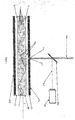
- Figure 1 shows a first embodiment of the apparatus of the present invention used to detect breakthrough in a laser drilling process.
- a target sample to be drilled is in the form of a catheter 3 having a hollow channel, or lumen 2. This channel 2 may be of narrow bore.
- An optical source 10 in the form of a drilling laser is provided for the drilling of holes in the wall 13 of the catheter 3.
- An optical fiber in the form of a side emitting fiber 1 is positioned inside the hollow channel 2, so that it is located perpendicular to the optical path of the drilling laser 10 and adjacent the catheter 3 so that the wall 13 to be drilled is positioned between the laser 10 and the side emitting fiber 1.
- An illumination light source 5 is positioned adjacent an end facet of the fiber 1 and adapted to direct light into the fiber 1.
- the light source 5 takes the form of a laser or a LED.
- a light detection system 16 is adapted to detect light emitted from the fiber 1.
- the detection system may be any suitable means for detection of optical rays, such as a CCD, a CMOS camera or a photodiode and image processing software.
- the detection system is positioned so as to capture light beams 17 which have been emitted radially by the fiber 1 and passed through the wall 13 of the sample 3.
- a directing means 12 is also provided, and positioned in the optical path of the drilling laser 10, in order to direct light into the light detection system 16.
- the purpose of the directing means 12 is to reflect only light radially emitted from the fiber 1 through the wall 13 of the sample 3 into the light detection system 16, while allowing the light from the laser 10 to pass through unaffected.
- an imaging system in the form of an optical microscope is located in front of the camera, in order to magnify the light prior to detection by the detection system 16.
- the side-emitting fiber 1 differs from a transmission fiber optic by the light leakage through its walls. Instead of guiding most of the incoming light from one end of the fiber to the other, as is the case in traditional optical fibers, a side-emitting fiber 1 allows the light to escape radially over a certain length.
- a side emitting fiber can be constructed in a variety of ways.
- One method involves designing the fiber to allow leakage of light at the interface between the fiber core and its outer core.
- Another method involves providing the fiber with a plurality of scattering centres 4 distributed throughout the length of the fiber 1, so that light will be scattered when it impacts the scattering centres.
- the scattering centres can be created in the optical fiber 1 by the appropriate selection of the refractive index of the fiber cladding relative to that of the core, causing the light to leak through the cladding.
- Another technique of achieving scattering centres is by providing the core of the fiber with microbends, so that the transmitted optical beam will meet areas locally not meeting the condition for total internal reflection, in order that scattering centres will occur at each microbend of the core.
- fluorescent or scattering particles can be added to either the core or the cladding of the fiber during its extrusion.
- light from the illumination light source 5 should first be directed into the side-emitting fiber 1. As the light 5 passes through the optical fiber 1, it will travel along the length of the fiber, reflecting between the fiber sidewalls 7 and 8, and emitting radially from the fiber as it interacts with the scattering centres 4.
- the drilling process can begin, by focussing the drilling laser 10 at the desired drilling point 11 of a hole in the wall 13 of the target sample (in this case the catheter tube 3), and powering it on, so that it emits a laser beam directed on the drilling point 11.
- a control "off" signal from a control processor which takes a signal from the detector 16 may be automatically sent to the drilling laser 10, or to an external device, to stop the drilling.
- a control processor which takes a signal from the detector 16
- the processing of light captured by the detector can be performed in a number of different ways.
- the detector may for example create an image of the light it captures, which is then analysed by the image-processing software to determine whether breakthrough has in fact occurred.
- Figure 2 details an alternative embodiment of the invention.
- the same reference numerals are used in respect of the same components as that of the first embodiment.
- the detecting means 16 is now placed at the end facet 6 of the side emitting optical fiber 1.
- the light from the drilling laser 10 penetrates the wall 13 of the catheter 3 and is absorbed by the fiber 1 and transmitted along its length to its end facet.
- the light transmitted along the fiber is then detected by the light detection system 16.
- This light may again optionally have been magnified first by an optical microscope located in front of the detection system 16. It will be noted that in this embodiment no separate illumination light source is necessary, as breakthrough is detected when absorbed light from the drilling laser 10 is detected by the detecting means 16 at the end facet 6 of the fiber 1.
- the drilling laser 10 will continue to machine the wall 13 of the catheter 3.
- the drilling laser 10 will enter the channel or lumen 2 of the catheter and will impact the side emitting fiber 1. If the fiber were not present, the drilling laser would impact the back wall 14 of the catheter 3, causing undesirable damage to the back wall 14.
- the wall 14 is protected against the drilling laser 10 impact by the side emitting fiber 1.
- the laser beam On impacting the side emitting fiber 1 inside the catheter channel 2, the laser beam will be scattered, causing the laser beam's energy to dissipate. The fiber will also absorb some of the energy of the drilling laser beam.
- the degree of scattering and absorption will be such that the remaining energy in the dispersed laser beams will be below the threshold value required to cause damage to the catheter wall. Therefore, placing the side emitting fiber 1 within the tube 3 has the added advantage of protecting the back wall from drilling damage, by scattering and absorbing the drilling laser beam once breakthrough on the front wall 13 has occurred, and before the detection system 16 has detected that breakthrough has occurred and any indicator or laser off signal is generated.
- the side emitting fiber system may also be used in process control, as an offline measurement tool. This is achieved by placing a side emitting optical fiber 1 adjacent the tube 3 at those locations where holes were intended to be present after the drilling process, and perpendicular to the optical path which would have been taken by the drilling laser when the holes were being drilled.
- a detector 16 and an illumination source 5 should also be located in the same positions as those shown in Figure 1 . When the optical fiber 1 is illuminated by the illumination source 5, the radially emitted light will pass through any completed holes in the tube 3. The detector 16 can then capture the image, while the image-processing software will automatically detect and count the number of completed holes. This light may optionally have been magnified first by an optical microscope located in front of the detector 16. It will be appreciated that the hole shape and size, and the location of the holes, can also be analysed using pattern-recognition algorithms within the image processing software.
- the present invention provides numerous advantages over the prior art techniques of detecting hole breakthrough. It provides an efficient and accurate means of detecting hole breakthrough.
- the apparatus of the present invention can also be used to detect holes of diameters within the range 1-10000 microns. Furthermore, it can be used to detect large numbers of bored holes. It can also detect holes that are to be machined in difficult to access locations on a sample. Furthermore, it minimizes the damage to the backwall of a catheter which can occur after breakthrough has occurred.
Landscapes
- Engineering & Computer Science (AREA)
- Physics & Mathematics (AREA)
- Optics & Photonics (AREA)
- Health & Medical Sciences (AREA)
- Plasma & Fusion (AREA)
- Mechanical Engineering (AREA)
- Life Sciences & Earth Sciences (AREA)
- Pulmonology (AREA)
- Biophysics (AREA)
- Anesthesiology (AREA)
- Biomedical Technology (AREA)
- Heart & Thoracic Surgery (AREA)
- Hematology (AREA)
- Animal Behavior & Ethology (AREA)
- General Health & Medical Sciences (AREA)
- Public Health (AREA)
- Veterinary Medicine (AREA)
- Length Measuring Devices By Optical Means (AREA)
- Laser Beam Processing (AREA)
Priority Applications (2)
| Application Number | Priority Date | Filing Date | Title |
|---|---|---|---|
| EP08151847A EP2093011A1 (fr) | 2008-02-22 | 2008-02-22 | Procédé et appareil pour détecter le perçage complet d'un trou par lasern utilisants une fibre optique |
| PCT/EP2009/052090 WO2009103815A1 (fr) | 2008-02-22 | 2009-02-20 | Procédé et appareil pour détecter une percée de trou lors d'un procédé de perçage par laser, à l'aide d'une fibre optique |
Applications Claiming Priority (1)
| Application Number | Priority Date | Filing Date | Title |
|---|---|---|---|
| EP08151847A EP2093011A1 (fr) | 2008-02-22 | 2008-02-22 | Procédé et appareil pour détecter le perçage complet d'un trou par lasern utilisants une fibre optique |
Publications (1)
| Publication Number | Publication Date |
|---|---|
| EP2093011A1 true EP2093011A1 (fr) | 2009-08-26 |
Family
ID=39577777
Family Applications (1)
| Application Number | Title | Priority Date | Filing Date |
|---|---|---|---|
| EP08151847A Withdrawn EP2093011A1 (fr) | 2008-02-22 | 2008-02-22 | Procédé et appareil pour détecter le perçage complet d'un trou par lasern utilisants une fibre optique |
Country Status (2)
| Country | Link |
|---|---|
| EP (1) | EP2093011A1 (fr) |
| WO (1) | WO2009103815A1 (fr) |
Cited By (4)
| Publication number | Priority date | Publication date | Assignee | Title |
|---|---|---|---|---|
| DE102016105567A1 (de) * | 2016-03-24 | 2017-09-28 | Eissmann Automotive Deutschland Gmbh | Verfahren zum Einbringen einer definierten Schwächungslinie mit einem gepulsten Laserstrahl durch Materialabtrag an einem Überzugsmaterial |
| EP3351199A1 (fr) * | 2010-12-29 | 2018-07-25 | Biosense Webster (Israel) Ltd. | Tresse avec conducteurs de signal intégré |
| US11440140B2 (en) | 2017-04-12 | 2022-09-13 | Eissmann Automotive Deutschland Gmbh | Method for introducing a defined weakening line by means of a pulsed laser beam via material removal on a cover material |
| DE102021108496A1 (de) | 2021-04-06 | 2022-10-06 | Trumpf Laser- Und Systemtechnik Gmbh | Vorrichtung und Verfahren zur Ermittlung einer Standzeit eines Werkstückprüflings bei Laserbestrahlung |
Families Citing this family (1)
| Publication number | Priority date | Publication date | Assignee | Title |
|---|---|---|---|---|
| US9102006B1 (en) | 2012-05-11 | 2015-08-11 | W. L. Gore & Associates, Inc. | Lighted mandrel for trimming medical devices |
Citations (8)
| Publication number | Priority date | Publication date | Assignee | Title |
|---|---|---|---|---|
| CA1138936A (fr) * | 1979-01-08 | 1983-01-04 | Franklin H. Fribourg | Methode et outil de percage au laser |
| US4766285A (en) * | 1985-09-16 | 1988-08-23 | Commissariat A L'energie Atomique | Apparatus for the real time checking of a total penetration weld for a joint which cannot be directly observed |
| JPH01143780A (ja) * | 1987-11-30 | 1989-06-06 | Toshiba Corp | 貫通孔の加工装置 |
| EP0347053A2 (fr) * | 1988-06-13 | 1989-12-20 | ROLLS-ROYCE plc | Perforer des pièces avec laser |
| US5227098A (en) * | 1990-04-26 | 1993-07-13 | Ae Turbine Components Limited | Laser drilling |
| GB2318538A (en) * | 1996-10-26 | 1998-04-29 | David Raymond Hicks | Laser/electron beam drilling |
| US20030191452A1 (en) * | 2002-04-04 | 2003-10-09 | Meglin Allen J. | Catheter and method of fluid removal from a body cavity |
| EP1661658A1 (fr) * | 2004-11-30 | 2006-05-31 | Delphi Technologies, Inc. | Dispositif de fabrication d'un trou au moyen de rayonnement laser |
-
2008
- 2008-02-22 EP EP08151847A patent/EP2093011A1/fr not_active Withdrawn
-
2009
- 2009-02-20 WO PCT/EP2009/052090 patent/WO2009103815A1/fr active Application Filing
Patent Citations (8)
| Publication number | Priority date | Publication date | Assignee | Title |
|---|---|---|---|---|
| CA1138936A (fr) * | 1979-01-08 | 1983-01-04 | Franklin H. Fribourg | Methode et outil de percage au laser |
| US4766285A (en) * | 1985-09-16 | 1988-08-23 | Commissariat A L'energie Atomique | Apparatus for the real time checking of a total penetration weld for a joint which cannot be directly observed |
| JPH01143780A (ja) * | 1987-11-30 | 1989-06-06 | Toshiba Corp | 貫通孔の加工装置 |
| EP0347053A2 (fr) * | 1988-06-13 | 1989-12-20 | ROLLS-ROYCE plc | Perforer des pièces avec laser |
| US5227098A (en) * | 1990-04-26 | 1993-07-13 | Ae Turbine Components Limited | Laser drilling |
| GB2318538A (en) * | 1996-10-26 | 1998-04-29 | David Raymond Hicks | Laser/electron beam drilling |
| US20030191452A1 (en) * | 2002-04-04 | 2003-10-09 | Meglin Allen J. | Catheter and method of fluid removal from a body cavity |
| EP1661658A1 (fr) * | 2004-11-30 | 2006-05-31 | Delphi Technologies, Inc. | Dispositif de fabrication d'un trou au moyen de rayonnement laser |
Cited By (9)
| Publication number | Priority date | Publication date | Assignee | Title |
|---|---|---|---|---|
| EP3351199A1 (fr) * | 2010-12-29 | 2018-07-25 | Biosense Webster (Israel) Ltd. | Tresse avec conducteurs de signal intégré |
| DE102016105567A1 (de) * | 2016-03-24 | 2017-09-28 | Eissmann Automotive Deutschland Gmbh | Verfahren zum Einbringen einer definierten Schwächungslinie mit einem gepulsten Laserstrahl durch Materialabtrag an einem Überzugsmaterial |
| WO2017162397A1 (fr) | 2016-03-24 | 2017-09-28 | Eissmann Automotive Deutschland Gmbh | Procédé pour ménager une ligne d'affaiblissement définie, au moyen d'un faisceau laser pulsé, par enlèvement de matière, sur un matériau de revêtement |
| DE102016105567B4 (de) | 2016-03-24 | 2018-05-24 | Eissmann Automotive Deutschland Gmbh | Verfahren zum Einbringen einer definierten Schwächungslinie mit einem gepulsten Laserstrahl durch Materialabtrag an einem Überzugsmaterial |
| CN109311122A (zh) * | 2016-03-24 | 2019-02-05 | 艾斯曼汽车德国有限责任公司 | 用于借助脉冲激光束通过在覆盖材料上进行材料去除来引入限定的弱化线的方法 |
| CN109311122B (zh) * | 2016-03-24 | 2020-11-17 | 艾斯曼汽车德国有限责任公司 | 用于借助脉冲激光束通过在覆盖材料上进行材料去除来引入限定的弱化线的方法 |
| US10953496B2 (en) | 2016-03-24 | 2021-03-23 | Eissmann Automotive Deutschland Gmbh | Method for introducing a defined tear line by means of a pulsed laser beam via material removal on a cover material |
| US11440140B2 (en) | 2017-04-12 | 2022-09-13 | Eissmann Automotive Deutschland Gmbh | Method for introducing a defined weakening line by means of a pulsed laser beam via material removal on a cover material |
| DE102021108496A1 (de) | 2021-04-06 | 2022-10-06 | Trumpf Laser- Und Systemtechnik Gmbh | Vorrichtung und Verfahren zur Ermittlung einer Standzeit eines Werkstückprüflings bei Laserbestrahlung |
Also Published As
| Publication number | Publication date |
|---|---|
| WO2009103815A1 (fr) | 2009-08-27 |
Similar Documents
| Publication | Publication Date | Title |
|---|---|---|
| EP2093011A1 (fr) | Procédé et appareil pour détecter le perçage complet d'un trou par lasern utilisants une fibre optique | |
| US4055382A (en) | Testing method for the separate determination of varying work surface flaws and arrangement for said method | |
| JP4347688B2 (ja) | 光ファイバー装置 | |
| CN102053056B (zh) | 分析装置以及粒子摄像方法 | |
| CN102132146A (zh) | 用于检测陶瓷过滤器主体中的缺陷的系统和方法 | |
| US20240118536A1 (en) | Detection of optical surface of patient interface for ophthalmic laser applications using a non-confocal configuration | |
| JP2019215321A (ja) | 溶液に浸された眼用レンズの屈折力および厚さを検査するためのシステムおよび方法 | |
| EP1818013A1 (fr) | Systeme evanescent de catheter | |
| JP2012013698A (ja) | 工具摩耗定量化システム及び方法 | |
| KR20110011644A (ko) | 광섬유 케이블 커넥터내의 광섬유 인터페이스의 단말처리 품질을 확인하기 위한 방법 및 장치 | |
| WO2017022885A1 (fr) | Appareil d'analyse de cellules utilisant une pluralité de lasers | |
| JP2014191242A (ja) | 内面検査装置 | |
| JP2003247812A (ja) | 油膜厚さ測定装置付き軸受 | |
| JP2710879B2 (ja) | レーザ測定方法及び装置 | |
| JP2005536741A (ja) | レーザーを基礎とする血液分析システムにおける後方散乱を検出するための装置 | |
| US8396245B2 (en) | Device and method for visualizing positions on a surface | |
| WO1998053305A1 (fr) | Procedes et appareil de detection de defauts de surface d'une fibre optique | |
| EP3527974B1 (fr) | Dispositifs d'inspection et procédés d'inspection d'une fente | |
| US6930769B1 (en) | Optical sensor module tester | |
| JP2007155384A (ja) | 欠陥検査装置及び欠陥検査方法 | |
| JP6234274B2 (ja) | 内面形状計測方法および装置 | |
| IL209276A (en) | Hollow core waveguide for ultrasonic laser production | |
| JP2007024638A (ja) | レーザートーチの検査システムおよび検査方法 | |
| JP3642108B2 (ja) | シンチレーションファイバ束の遮光性能試験装置及び放射線の深部線量測定装置 | |
| JPH10307010A (ja) | 管内検査方法及び管内検査装置 |
Legal Events
| Date | Code | Title | Description |
|---|---|---|---|
| PUAI | Public reference made under article 153(3) epc to a published international application that has entered the european phase |
Free format text: ORIGINAL CODE: 0009012 |
|
| AK | Designated contracting states |
Kind code of ref document: A1 Designated state(s): AT BE BG CH CY CZ DE DK EE ES FI FR GB GR HR HU IE IS IT LI LT LU LV MC MT NL NO PL PT RO SE SI SK TR |
|
| AX | Request for extension of the european patent |
Extension state: AL BA MK RS |
|
| AKX | Designation fees paid | ||
| REG | Reference to a national code |
Ref country code: DE Ref legal event code: 8566 |
|
| STAA | Information on the status of an ep patent application or granted ep patent |
Free format text: STATUS: THE APPLICATION IS DEEMED TO BE WITHDRAWN |
|
| 18D | Application deemed to be withdrawn |
Effective date: 20100227 |