EP2092971B1 - Apparatus for screening drilling mud - Google Patents
Apparatus for screening drilling mud Download PDFInfo
- Publication number
- EP2092971B1 EP2092971B1 EP09006866A EP09006866A EP2092971B1 EP 2092971 B1 EP2092971 B1 EP 2092971B1 EP 09006866 A EP09006866 A EP 09006866A EP 09006866 A EP09006866 A EP 09006866A EP 2092971 B1 EP2092971 B1 EP 2092971B1
- Authority
- EP
- European Patent Office
- Prior art keywords
- basket
- feed
- screen
- flow
- filtrate
- Prior art date
- Legal status (The legal status is an assumption and is not a legal conclusion. Google has not performed a legal analysis and makes no representation as to the accuracy of the status listed.)
- Active
Links
- 238000012216 screening Methods 0.000 title claims abstract description 27
- 238000005553 drilling Methods 0.000 title abstract description 11
- 239000007787 solid Substances 0.000 claims abstract description 30
- 230000000712 assembly Effects 0.000 claims abstract description 25
- 238000000429 assembly Methods 0.000 claims abstract description 25
- 239000000706 filtrate Substances 0.000 claims abstract description 23
- 230000003068 static effect Effects 0.000 claims description 13
- 239000007788 liquid Substances 0.000 claims description 12
- 239000000203 mixture Substances 0.000 claims description 12
- 238000012545 processing Methods 0.000 claims description 10
- 230000037361 pathway Effects 0.000 claims 2
- 239000012530 fluid Substances 0.000 abstract description 35
- 230000015572 biosynthetic process Effects 0.000 description 4
- 238000005755 formation reaction Methods 0.000 description 4
- 239000002245 particle Substances 0.000 description 4
- 230000000717 retained effect Effects 0.000 description 4
- 230000008901 benefit Effects 0.000 description 3
- VTYYLEPIZMXCLO-UHFFFAOYSA-L Calcium carbonate Chemical compound [Ca+2].[O-]C([O-])=O VTYYLEPIZMXCLO-UHFFFAOYSA-L 0.000 description 2
- 238000000034 method Methods 0.000 description 2
- 238000011144 upstream manufacturing Methods 0.000 description 2
- 238000013459 approach Methods 0.000 description 1
- 229910000019 calcium carbonate Inorganic materials 0.000 description 1
- 230000008878 coupling Effects 0.000 description 1
- 238000010168 coupling process Methods 0.000 description 1
- 238000005859 coupling reaction Methods 0.000 description 1
- 238000005520 cutting process Methods 0.000 description 1
- 230000003247 decreasing effect Effects 0.000 description 1
- 238000006073 displacement reaction Methods 0.000 description 1
- 238000001035 drying Methods 0.000 description 1
- 229910052500 inorganic mineral Inorganic materials 0.000 description 1
- 238000012423 maintenance Methods 0.000 description 1
- 239000000463 material Substances 0.000 description 1
- 239000011707 mineral Substances 0.000 description 1
- 238000012986 modification Methods 0.000 description 1
- 230000004048 modification Effects 0.000 description 1
- 239000011236 particulate material Substances 0.000 description 1
- 239000011148 porous material Substances 0.000 description 1
- 230000008569 process Effects 0.000 description 1
- 150000003839 salts Chemical class 0.000 description 1
Images


Classifications
-
- E—FIXED CONSTRUCTIONS
- E21—EARTH DRILLING; MINING
- E21B—EARTH DRILLING, e.g. DEEP DRILLING; OBTAINING OIL, GAS, WATER, SOLUBLE OR MELTABLE MATERIALS OR A SLURRY OF MINERALS FROM WELLS
- E21B21/00—Methods or apparatus for flushing boreholes, e.g. by use of exhaust air from motor
- E21B21/06—Arrangements for treating drilling fluids outside the borehole
- E21B21/063—Arrangements for treating drilling fluids outside the borehole by separating components
- E21B21/065—Separating solids from drilling fluids
-
- B—PERFORMING OPERATIONS; TRANSPORTING
- B01—PHYSICAL OR CHEMICAL PROCESSES OR APPARATUS IN GENERAL
- B01D—SEPARATION
- B01D33/00—Filters with filtering elements which move during the filtering operation
- B01D33/01—Filters with filtering elements which move during the filtering operation with translationally moving filtering elements, e.g. pistons
- B01D33/03—Filters with filtering elements which move during the filtering operation with translationally moving filtering elements, e.g. pistons with vibrating filter elements
- B01D33/0307—Filters with filtering elements which move during the filtering operation with translationally moving filtering elements, e.g. pistons with vibrating filter elements with bag, cage, hose, tube, sleeve or the like filtering elements
- B01D33/033—Filters with filtering elements which move during the filtering operation with translationally moving filtering elements, e.g. pistons with vibrating filter elements with bag, cage, hose, tube, sleeve or the like filtering elements arranged for outward flow filtration
- B01D33/0338—Filters with filtering elements which move during the filtering operation with translationally moving filtering elements, e.g. pistons with vibrating filter elements with bag, cage, hose, tube, sleeve or the like filtering elements arranged for outward flow filtration open ended
-
- B—PERFORMING OPERATIONS; TRANSPORTING
- B01—PHYSICAL OR CHEMICAL PROCESSES OR APPARATUS IN GENERAL
- B01D—SEPARATION
- B01D33/00—Filters with filtering elements which move during the filtering operation
- B01D33/01—Filters with filtering elements which move during the filtering operation with translationally moving filtering elements, e.g. pistons
- B01D33/03—Filters with filtering elements which move during the filtering operation with translationally moving filtering elements, e.g. pistons with vibrating filter elements
- B01D33/0346—Filters with filtering elements which move during the filtering operation with translationally moving filtering elements, e.g. pistons with vibrating filter elements with flat filtering elements
- B01D33/0376—Filters with filtering elements which move during the filtering operation with translationally moving filtering elements, e.g. pistons with vibrating filter elements with flat filtering elements supported
-
- B—PERFORMING OPERATIONS; TRANSPORTING
- B01—PHYSICAL OR CHEMICAL PROCESSES OR APPARATUS IN GENERAL
- B01D—SEPARATION
- B01D33/00—Filters with filtering elements which move during the filtering operation
- B01D33/35—Filters with filtering elements which move during the filtering operation with multiple filtering elements characterised by their mutual disposition
- B01D33/37—Filters with filtering elements which move during the filtering operation with multiple filtering elements characterised by their mutual disposition in parallel connection
- B01D33/39—Filters with filtering elements which move during the filtering operation with multiple filtering elements characterised by their mutual disposition in parallel connection concentrically or coaxially
-
- B—PERFORMING OPERATIONS; TRANSPORTING
- B07—SEPARATING SOLIDS FROM SOLIDS; SORTING
- B07B—SEPARATING SOLIDS FROM SOLIDS BY SIEVING, SCREENING, SIFTING OR BY USING GAS CURRENTS; SEPARATING BY OTHER DRY METHODS APPLICABLE TO BULK MATERIAL, e.g. LOOSE ARTICLES FIT TO BE HANDLED LIKE BULK MATERIAL
- B07B1/00—Sieving, screening, sifting, or sorting solid materials using networks, gratings, grids, or the like
- B07B1/46—Constructional details of screens in general; Cleaning or heating of screens
-
- B—PERFORMING OPERATIONS; TRANSPORTING
- B07—SEPARATING SOLIDS FROM SOLIDS; SORTING
- B07B—SEPARATING SOLIDS FROM SOLIDS BY SIEVING, SCREENING, SIFTING OR BY USING GAS CURRENTS; SEPARATING BY OTHER DRY METHODS APPLICABLE TO BULK MATERIAL, e.g. LOOSE ARTICLES FIT TO BE HANDLED LIKE BULK MATERIAL
- B07B13/00—Grading or sorting solid materials by dry methods, not otherwise provided for; Sorting articles otherwise than by indirectly controlled devices
- B07B13/14—Details or accessories
- B07B13/16—Feed or discharge arrangements
Definitions
- the present invention relates to vibratory screening apparatus suitable for use with drilling fluids, mineral processing, classification, and dewatering, and the like.
- an initial screen assembly with a mesh size of around 10 to 80 (wires per inch), for example, about 20, and the first and second screen assemblies would have a mesh size of around 40 to 325, conveniently 100 to 250 for example about 200.
- the feed is passed only through the initial coarse screen.
- Fig. 1 shows schematically one embodiment of a vibratory screen apparatus 1 of the invention with an outer housing (indicated schematically) 2, in which is mounted on springs 3, a basket 4.
- the basket is generally box shaped with pairs of circumferentially extending inwardly projecting flanges 5 height on the basket side walls 6, for supporting respective ones of a stack 7 of screen assemblies 8 separated by flow directing trays 9.
- a vibrator unit 10 is secured to the top 11 of the basket. (Alternatively, the vibrator 10 could be mounted on a side of the basket 4, or incorporated into or within the structure of the basket 4.
- the interior 12 of the basket 4 is divided into a series of levels 13 between neighbouring screen assemblies 8 and flow directing trays 9.
- Figs 2A /B, 3A/B and 4A/B show different configurations of the distributor 15 for providing different feed flow arrangements through the screen assemblies 8, which are indicated as A, B and C, respectively, in Figs 2 to 5 .
- FIG 2A shows the inside passage 17 and interior 12 of the basket 14, with an upper flap valve 20' raised to open an upper connecting opening 19' connecting the passage 17 and first level 13 1 above the upper flow deflector tray 9'.
- An intermediate flap valve 20'' is raised to close an intermediate connecting opening 19'' connecting the passage 17 and second level 13 2 between the upper and lower flow deflector trays 9', 9'' whilst simultaneously opening an intermediate level opening 21' in passage 17.
- a lower flap valve 20''' is lowered to open a lower connecting opening 19''' connecting the passage 17 and a fourth level 134 below the lower flow deflector tray 9''.
- Fig. 4A shows the distributor in the inside passage 17 configured so that the upper flap valve 20' is raised as before.
- the intermediate flap valve 20" is lowered so as to open the intermediate connecting opening 19'' whilst simultaneously closing the intermediate level passage opening 21' and the lower flap 20''' is raised to close the lower connecting opening 19''' whilst opening the bottom passage opening 21'''.
- That part 23' of the filtrate 23 from the coarse screen 8' passing into the inside passage 17, is directed onto the first screen 8'' and then out of the bottom opening 21'' of the inside passage 17, by-passing the second screen 8'''.
- the outside passage 18 is configured as in Fig.
- That part 38 of the fluid 33 retained on the second screen 36 is passed through the second deck screen 36 (the solid particulate material 49 retained thereon being "walked up” the screen 36 in the usual way - see Fig. 8B ), as indicated by the double headed arrows 50.
- This part 50 of the fluid flow 33 is then passed through a second deck end wall opening 51 and down a central vertically extending conduit 52 underneath the deflector plates 43.
- a closure panel 53 seals a third deck end wall opening 54, below the second deck end wall opening 51, thereby preventing this part 50 of the fluid flow 33 from entering the third deck 47.
- the module 28 as described above, may be readily reconfigured for serial operation whereby the whole of the fluid is passes through each one of the first, second and third deck screens, 31, 36, 46, as shown in Figs. 9-10 .
- the weir 39 is replaced by a high wall 57 which ensures that the whole of the fluid flow 33 is passed through the second deck screen 36.
- the fluid flow 58 then passes out through the second deck end wall opening 51 into the central vertical conduit 52.
- the bottom opening 55 is sealed by a closure plate 59 whilst the closure panel 53 of the third deck end wall opening 54 is opened so that the fluid flow 58 is routed from the central vertical conduit 52 into the third deck 47 and passed through the screen 46 thereof into the sump 56.
- Figs 11 to 13 show a vibratory screening apparatus 1 of the invention with a generally conventional form of static outer housing 2, in which is mounted on springs 3, and a basket 4 with a vibrator device 10.
- the static housing 2 has a base support 60 which includes a sump 61 for receiving filtrate 62 from the basket 4, and a feed device support portion 63 mounting a feed device 64.
- the feed device 64 comprises a header tank 65 for receiving a liquid and solids mixture feed 66, and having a feed chute 67 extending out therefrom above the basket 4 so as to pass said feed 66 into the basket 4.
- a static flow distributor 24 mounted on the header tank portion 65 of the static housing 2, and coupled to the floating basket 4 via flexible conduits 26.
- the flow distributor 15 is incorporated in the floating basket 4.
Abstract
Description
- The present invention relates to vibratory screening apparatus suitable for use with drilling fluids, mineral processing, classification, and dewatering, and the like.
- In
US 2,943,679 the requirement for maintaining control of the content of a drilling fluid, especially the circulating material (solid particles is described. - Vibratory screening apparatus is widely used in the oil drilling industry for removing drill cuttings from drilling fluids, and over the years various improvements have been made to the screens used therein, methods for mounting the screens etc to improve ease of use, reduce maintenance etc. A particular problem in offshore platform oil drilling is, however, that platform real estate is very restricted and extremely expensive. There is accordingly a need to improve the efficiency of vibratory screening apparatus in relation to the physical size thereof.
- In
US 3,452,868 a vibratory screening apparatus is described wherein the feed is divided into parallel flows that are directed to various screens in a stack of screens. - The present invention provides a basket suitable for use in a vibratory screening apparatus, for use in removing solids from a liquid and solids mixture feed, said basket mounting a stack of at least three screen assemblies, with superposed screen assemblies separated from each other by a respective flow directing tray:
- said stack of at least three screen assemblies being provided with a flow distributor formed and arranged so as to be switchable between a plurality of different flow directing configurations, including;
- a) a parallel processing configuration in which said flow distributor receives filtrate from a primary upper screen assembly and divides said filtrate into at least a first feed stream and a second feed stream, directs said feed streams onto respective ones of first and second screen assemblies, and receives filtrate from said respective flow directing trays; and
- b) an intensive screening configuration in which the whole of the filtrate from a primary upper screen assembly is directed onto a first screen assembly and the whole of the filtrate from said first screen assembly is directed onto a second screen assembly.
- The present invention also provides a vibratory screening apparatus for use in removing solids from a liquid and solids mixture feed, said apparatus comprising a basket as described above and a static outer housing, said housing comprising: a base support formed and arranged for mounting at least one said basket in floating manner so as to be vibratable, in use of the apparatus, by a vibrator device formed and arranged for vibrating said basket, said base support having a sump for receiving filtrate from said basket, and said housing having a feed device formed and arranged for directing said liquid and solids mixture feed to said basket mounted in said base support.
- With an apparatus of the present invention, the size of apparatus required to process a given volume of feed is substantially reduced compared with conventional apparatus, since a substantially increased effective screen surface area can be accommodated with relatively little or no increase in the size of the apparatus by means of stacking a plurality of screen assemblies within a single basket and using a flow distributor to route multiple flows in parallel through different screens in the stack.
- Advantageously the distributor is formed and arranged so as to be switchable between a plurality of different flow directing configurations. Conveniently said plurality of flow directing configurations includes an intensive screening configuration in which the whole of the feed is directed onto said first screen assembly and the whole of the filtrate from said first screen assembly is directed onto said second screen assembly. Additionally there may be provided a restricted feed capacity configuration in which the whole of the feed is directed onto only one of said first and second screen assemblies, and the filtrate therefrom exhausted directly from the apparatus without passing through the other one said first and second screen assemblies. Such a configuration is useful for basic fluid processing where high efficiency or high volume processing are not required and a reduced number of screens in operation reduces operating cost for screens consumed.
- Advantageously the mesh sizes of the various screens are selected to suit the particular distributor configuration being employed and/or the loading of the mixture (% solids content), the particle size of the solids, and/or the particle size distribution of the solids. Thus for example in a configuration where the feed is divided into one portion passing through the first screen and not the second, and another portion passing through the second screen and not the first, the first and second screens would normally have the same mesh size. On the other hand in a configuration where the whole of the feed is passed successively through both the first and second screens, then the second screen would normally have a finer mesh size than the first screen.
- In general the distributor will comprise a plurality of passages provided with valves, typically flap valves, sleeve valves or plug valves, or closure plates etc, for selective opening or closing of different passages. The distributor may be mounted in either the static housing or on the floating basket. It is also possible, in principle, for part of the distributor to be mounted in the static housing and part on the floating basket. Where a greater or lesser part of the distributor is mounted in the static housing, then the distributor is generally provided with flexible conduit portions defining at least part of the passages, for coupling the passages from the static housing to the floating basket.
- The passages of the distributor may be defined in various different ways. Conveniently they are defined by walls extending downwardly inside a downwardly extending chamber so as to provide a lateral subdivision of the chamber into individual passages providing predetermined proportions of the distributor flow capacity. Thus, for example, the distributor may be formed and arranged with one or more first flow passages for transmitting said first feed stream, and one or more second flow passages for transmitting said second feed stream.
- It is generally preferred that vibratory screen apparatus should have a plurality of screen assembly stages with decreasing mesh size, i.e. meshes of successively finer cut. It will accordingly be appreciated that in addition to having first and second screen assemblies, with similar mesh size, formed and arranged for intercepting said first and second feed streams respectively, the vibratory basket may also have one or more further screen assemblies with different mesh size upstream and/or downstream of said first and second screen assemblies. Conveniently there is provided upstream of first and second screen assemblies, an initial, coarser mesh size, screen assembly and the vibratory screening apparatus is formed and arranged so that substantially the whole of the liquid and solids mixture feed is directed through said initial screen assembly, before being divided into said at least first and second feed streams. In such cases there would generally be used an initial screen assembly with a mesh size of around 10 to 80 (wires per inch), for example, about 20, and the first and second screen assemblies would have a mesh size of around 40 to 325, conveniently 100 to 250 for example about 200. In yet another possible distributor configuration which could also be provided, the feed is passed only through the initial coarse screen.
- It will also be appreciated that, whilst in accordance with normal practice, all of the separated out solids are disposed of in one way or another, in certain cases it is advantageous to retain within the recycled drilling mud fluid, some solids within a particular size range. Typically these may comprise one or more of sized salt, sized calcium carbonate, and other suitable solids, which are selected to be of a size compatible with minimising formation damage during drilling of a specific formation such as an oil reservoir or a zone where fluid can be lost to the formation. In this instance solids above a specified size can be removed with a top screen and rejected, while solids of a smaller size but greater than a second size, can be separated with the second screen and subsequently returned to the drilling fluid mud system, with solids smaller than those removed by the second screen but larger than a third size, may be removed with a third screen and rejected. In other cases it may be desirable to return only the largest size particle fraction separated out at the first screen, for return to the drilling fluid where this is used in formations with particularly large pore size.
- Various screen assemblies and screen mounting systems may be used in the apparatus and baskets of the present invention, including, for example, those described in our earlier patent publication
WO 03/013690 - The floating basket may be mounted in any convenient manner known in the art. Typically there is used a resilient mounting such as a coil spring or rubber block mounting, and the basket vibrated with an eccentrically rotating weight drive. Other forms of resilient mounting may be more convenient with other forms of drive, for example, a leaf spring mounting, with the basket being vibrated with an electromagnetic displacement drive being used to displace the basket against the return force of the spring mounting.
- Further preferred features and advantages of the invention will appear from the following detailed description given by way of example of preferred embodiments illustrated with reference to the accompanying drawings in which:
-
Fig. 1 is a schematic sectional elevation of a vibratory screening apparatus of the present invention; -
Figs. 2A to 4B are schematic vertical sections illustrating different flow paths through the stacked screens with different configurations of the flow distributor set up for parallel and series operation; -
Figs. 5A-C are schematic perspective end views of the basket of the apparatus also illustrating the flow paths in various different configurations of the flow distributor; -
Fig. 6 is a side elevation of a modified apparatus with a static flow distributor connected to a floating vibratory apparatus; -
Fig. 7 is a partly cut-away schematic perspective view of a further embodiment showing one module of a twin-module apparatus set up for parallel operation; -
Figs. 8A and 8B are vertical sections of the apparatus ofFig. 7 at A and B; -
Figs. 9-10 are corresponding views of the apparatus ofFigs. 7-8 , set up for series operation; -
Figs 11-12 are schematic general side elevations of vibratory screen apparatus of the invention showing the housing; and -
Fig. 13 is a schematic perspective view of the apparatus ofFig. 12 . -
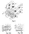
Fig. 1 shows schematically one embodiment of avibratory screen apparatus 1 of the invention with an outer housing (indicated schematically) 2, in which is mounted onsprings 3, a basket 4. (See below for more detailed description of housing.) The basket is generally box shaped with pairs of circumferentially extending inwardly projectingflanges 5 height on thebasket side walls 6, for supporting respective ones of astack 7 ofscreen assemblies 8 separated byflow directing trays 9. Avibrator unit 10 is secured to thetop 11 of the basket. (Alternatively, thevibrator 10 could be mounted on a side of the basket 4, or incorporated into or within the structure of the basket 4. Theinterior 12 of the basket 4 is divided into a series oflevels 13 between neighbouringscreen assemblies 8 andflow directing trays 9. -
Figs. 2 A/B to 4 A/B show schematically adistributor 15 provided at oneend 16 of the floating basket 4. Thedistributor 15 is formed and arranged into inside andoutside passages Figs. 2A to 4A, and 2B to 4B , respectively, for connecting with thevarious levels 13 of theinterior 12 of the basket 4 viaopenings 19 controlled byflap valves 20. In some cases theflap valves 20 are additionally used to controlopenings 21 along the length of thepassages flap valves 20, as further described hereinbelow. -
Figs 2A /B, 3A/B and 4A/B show different configurations of thedistributor 15 for providing different feed flow arrangements through thescreen assemblies 8, which are indicated as A, B and C, respectively, inFigs 2 to 5 . - In more detail
Fig 2A shows theinside passage 17 andinterior 12 of the basket 14, with an upper flap valve 20' raised to open an upper connecting opening 19' connecting thepassage 17 andfirst level 131 above the upper flow deflector tray 9'. An intermediate flap valve 20'' is raised to close an intermediate connecting opening 19'' connecting thepassage 17 andsecond level 132 between the upper and lower flow deflector trays 9', 9'' whilst simultaneously opening an intermediate level opening 21' inpassage 17. A lower flap valve 20''' is lowered to open a lower connecting opening 19''' connecting thepassage 17 and afourth level 134 below the lower flow deflector tray 9''. In this configuration it may be seen that afeed 22 of liquid and solids is passed through a coarse mesh, (typically mesh size 20) upper screen 8' and thefiltrate 23 passed along the upper flow deflector tray 9' intopassage 17 and thence, bypassing a first, mid-level, screen 8'', onto a second, low-level, screen 8'''. In this configuration the whole of thefeed 22 is passed through the coarse screen 8' and only one of the first and second screens 8'',8'''. -
Figs. 3B shows thedistributor 15 configured so that the upper flap valve 20' is raised to open the upper connecting opening 19', the intermediate flap valve 20'' is lowered to open the intermediate connecting opening 19'' whilst simultaneously closing the intermediatelevel passage opening 21', and the lower flap 20''' is lowered to open the lower connecting opening 19''' whilst closing a bottom passage opening 21'' as before. In this configuration the whole of thefeed 22 is passed through the coarse screen 8' and then successively through each of the first and second screens 8'', 8''' thereby providing a more progressively finer screening of the feed (by using a finer mesh size in the second screen than in the first screen). -
Fig. 4A shows the distributor in theinside passage 17 configured so that the upper flap valve 20' is raised as before. Theintermediate flap valve 20" is lowered so as to open the intermediate connecting opening 19'' whilst simultaneously closing the intermediatelevel passage opening 21' and the lower flap 20''' is raised to close the lower connecting opening 19''' whilst opening the bottom passage opening 21'''. In this configuration of theinside passage 17 in thedistributor 15, that part 23' of thefiltrate 23 from the coarse screen 8' passing into theinside passage 17, is directed onto the first screen 8'' and then out of thebottom opening 21'' of theinside passage 17, by-passing the second screen 8'''. Theoutside passage 18 is configured as inFig. 2A so that the remaining part 23'' of thefiltrate 23 from the coarse screen 8' passing into theoutside passage 18, is directed onto the second screen 8''' by-passing the first screen 8''. It will be appreciated that in this configuration of thedistributor 15, the screen area available for screening of thefeed 22 is effectively double that used inFig. 2A /B and that available in a conventional vibratory screening apparatus basket of similar footprint. -
Figs. 5A - C are schematic perspective views of theend 16 of the basket 4 to which thedistributor 15 is coupled but with thedistributor 15 substantially removed for clarity, showing the flows in and out of thevarious openings 19 connecting thedistributor 15 to the interior 12 of the basket 4. -
Fig. 6 shows schematically another embodiment in which there is used adistributor 24 mounted on thestatic housing 2 and with its connectingopenings 19 coupled to thecorresponding levels 25 inside the floating basket 4 byflexible conduits 26. -
Fig. 7 shows a further embodiment of ascreening apparatus 27 of the invention which hasidentical twin modules 28, 29 (only one shown in detail). Each module has a first, coarse mesh, upper, scalping,deck 30 with a first, coarse mesh,screen 31 above a flow backtray 32.Fluid 33 to be screened is retained on thescreen 31 by an end wall 34. - Below the
first deck tray 32 is disposed asecond deck 35 comprising asecond screen 36 above arespective flowback tray 37. A certain amount of fluid 38 is retained on thesecond screen 36 by aweir 39 provided at the lower end 40 thereof. When the flow rate of the feed offluid 33 to be screened, exceeds the capacity of the second screen,part 41 of the fluid 38 overflows theweir 39 either directly into one or other of two vertically extendingconduits 42 at opposite sides of themodule 28, or onto one or other of twosloping deflector plates 43 which divert it into a respective one of theconduit 42, as shown by the single headed fluid flow arrows inFigs. 7-8 . - At the bottom 44 of the
vertical conduits 42 are provided rearwardly facingopenings 45 through which the divertedfluid 41 is directed onto thescreen 46 of athird deck 47 disposed below thesecond deck 35. Thus thispart 41 of thefluid flow 33 passes through thefirst deck screen 31 and thethird deck screen 46, by-passing the second deck screen 36 (see alsoFigs. 8A and 8B , in whichFig. 8A is a section through a central vertical plane at A, which extends through acentral portion 48 of themodule 28, with thedeflector plates 43; andFig. 8B is a vertical section through one of the vertically extending side conduits 42). - That part 38 of the fluid 33 retained on the
second screen 36 is passed through the second deck screen 36 (the solidparticulate material 49 retained thereon being "walked up" thescreen 36 in the usual way - seeFig. 8B ), as indicated by the double headedarrows 50. Thispart 50 of thefluid flow 33, is then passed through a second deck end wall opening 51 and down a central vertically extendingconduit 52 underneath thedeflector plates 43. A closure panel 53 seals a third deck end wall opening 54, below the second deck end wall opening 51, thereby preventing thispart 50 of thefluid flow 33 from entering thethird deck 47. Abottom opening 55 in the centralvertical conduit 52 allows thisfluid flow 50 to pass into thesump 56 of theapparatus 28 where it rejoins the other part 38 of thefluid flow 33, therespective parts fluid flow 33, being passed through thefirst deck screen 31 and then, in parallel, through a respective one of the second and third deck screens 36, 46. - The
module 28 as described above, may be readily reconfigured for serial operation whereby the whole of the fluid is passes through each one of the first, second and third deck screens, 31, 36, 46, as shown inFigs. 9-10 . In more detail theweir 39 is replaced by ahigh wall 57 which ensures that the whole of thefluid flow 33 is passed through thesecond deck screen 36. As before, thefluid flow 58 then passes out through the second deck end wall opening 51 into the centralvertical conduit 52. In this configuration, thebottom opening 55 is sealed by aclosure plate 59 whilst the closure panel 53 of the third deck end wall opening 54 is opened so that thefluid flow 58 is routed from the centralvertical conduit 52 into thethird deck 47 and passed through thescreen 46 thereof into thesump 56. - Each of the first and
second modules Fig. 13 ). With the significantly increased fluid processing capacity of the apparatus (in parallel mode) it will be appreciated that occasions will arise when the fluid feed is insufficient to maintain a high fluid level and short beach length on the screens, which can result in drying of the particulate solids on the beach portion of the screen and damage to the screens therefrom, and/or reduced efficiency of transportation of the particulate solids up the beach for discharge from the screen. In such circumstances damage to the screens can be minimized by restricting the fluid feed to only one of the twin modules. - A particular advantage of this type of embodiment is that, in its parallel configuration, a more even and controlled distribution of the fluid flow across the width of the module is obtained, thereby providing a more efficient screening. Another significant advantage is a significantly increased fluid screening capacity - which can approach almost 100% greater than with conventional screening apparatus of the same footprint.
- It will also be appreciated that various parameters of the modules may be made further configurable. Thus, for example, the weir height could be configurable for a series of different heights. Also the relative proportions of the central and side, vertical conduits could be selected to accommodate particular desired flow capacity proportions for the different fluid flow parts in parallel mode operation.
- It will further be appreciated that various modifications may be made to the above embodiments. Thus, for example, in place of a flow distributor system based on the use of closure plates and/or flap valves, there could be used one based on proportional valves and the like.
-
Figs 11 to 13 show avibratory screening apparatus 1 of the invention with a generally conventional form of staticouter housing 2, in which is mounted onsprings 3, and a basket 4 with avibrator device 10. In more detail thestatic housing 2 has abase support 60 which includes asump 61 for receivingfiltrate 62 from the basket 4, and a feeddevice support portion 63 mounting afeed device 64. Thefeed device 64 comprises aheader tank 65 for receiving a liquid andsolids mixture feed 66, and having afeed chute 67 extending out therefrom above the basket 4 so as to pass saidfeed 66 into the basket 4. In the case ofFig. 11 , there is provided astatic flow distributor 24 mounted on theheader tank portion 65 of thestatic housing 2, and coupled to the floating basket 4 viaflexible conduits 26. In the case ofFigs 12 and 13 , theflow distributor 15 is incorporated in the floating basket 4. - In the apparatus shown in
Fig. 13 it may be seen that the basket 4 has alateral divider 68 separating the basket into two independently operable basketfeed processing modules housing 2 has twoseparate feed chutes header tank 65 and formed and arranged for directing said liquid andsolids mixture feed feed processing modules chutes respective control gates feed 66 from theheader tank 65, so that the user has the option of using only one or other, or both, of themodules
Claims (15)
- A basket (4) suitable for use in a vibratory screening apparatus (1), for use in removing solids from a liquid and solids mixture feed, said basket (4) mounting a stack of at least three screen assemblies (8',8'',8'''), with superposed screen assemblies separated from each other by a respective flow directing tray (9',9''):said stack of at least three screen assemblies (8',8'',8''') being provided with a flow distributor (15) formed and arranged so as to be switchable between a plurality of different flow directing configurations, including;a) a parallel processing configuration in which said flow distributor receives filtrate from a primary upper screen assembly (8') and divides said filtrate into at least a first feed stream and a second feed stream, directs said feed streams onto respective ones of first (8'') and second (8''') screen assemblies, and receives filtrate from said respective flow directing trays(9''); andb) an intensive screening configuration in which the whole of the filtrate from a primary upper screen assembly (8') is directed onto a first screen assembly (8'') and the whole of the filtrate from said first screen assembly is directed onto a second screen assembly (8''').
- A basket (4) as claimed in claim 1 wherein said plurality of flow directing configurations includes a restricted feed capacity configuration in which the whole of the feed is directed onto only one of said first (8'') and second (8''') screen assemblies, and the filtrate therefrom exhausted directly from the apparatus (1) without passing through the other one of said first and second screen assemblies (8",8'").
- A basket as claimed in claim 1 or claim 2 wherein at least said primary screen assembly (8') has a different mesh size from at least one other said screen assembly (8",8'").
- A basket as claimed in any one of claims 1 to 3 wherein said first and second screen assemblies (8",8'") have the same mesh size.
- A basket as claimed in any one of claims 1 to 4 wherein said flow distributor (15) defines a plurality of flow pathways provided with flow control devices (20), for selective opening or at least partial closing of different passages (17,18).
- A basket as claimed in any one of claims 1 to 5 wherein at least one said flow control device (20) is selected from the group consisting essentially of flap valves (20',20'',20'''), sleeve valves, plug valves, and closure plates.
- A basket as claimed in claim 5 wherein at least one said flow control device (20) is comprised by a weir (39), formed and arranged for sub-dividing a said feed into a said first feed stream passing over said weir and a said second feed stream not passing over said weir.
- A basket as claimed in claim 7 wherein said weir (39) comprises a variable height weir.
- A basket as claimed in any one of claims 5 to 8 wherein said flow distributor (15) includes at least one wall formed and arranged for defining a plurality of laterally adjacent flow pathways.
- A basket as claimed any one of claims 1 to 9 wherein the flow distributor (15) is mounted on the basket (4).
- A basket as claimed any one of claims 1 to 9 wherein the flow distributor (15) is coupled to the basket (4) by flexible conduits.
- A basket as claimed in any one of claims 1 to 11 wherein said flow directing trays (9',9'') are formed and arranged so that substantially the whole of the filtrate from a screen assembly (8) directly above a said flow directing tray can be intercepted thereby, whereby said feed can be substantially fully divided by the flow distributor (15) into parallel first and second feed streams to respective ones of first and second screen assemblies (8'',8''').
- A vibratory screening apparatus (1) for use in removing solids from a liquid and solids mixture feed, said apparatus comprising a basket according to claim 1 and further comprising a static outer housing (2), said housing comprising: a base support (60) formed and arranged for mounting at least one said basket (4) in floating manner so as to be vibratable, in use of the apparatus, by a vibrator device (10) formed and arranged for vibrating said basket (4), said base support (60) having a sump (61) for receiving filtrate from said basket (4), and said housing (2) having a feed device (64) formed and arranged for directing said liquid and solids mixture feed to said basket (4) mounted in said base support (60).
- A vibratory screening apparatus as claimed in claim 13, wherein said basket forms part of a multi-basket assembly comprising a plurality of said baskets, mounted in said static housing, and wherein said housing has a feed distribution device formed and arranged for directing said liquid and solids mixture feed to at least one of said plurality of baskets.
- A vibratory screening apparatus (1) as claimed in claim 13, wherein said basket (4) further includes a lateral divider (68) defining independent feed processing modules (69,70), and wherein said housing has a feed distribution device (71-74) formed and arranged for directing said liquid and solids mixture feed to at least one of said basket feed processing modules (69,70).
Applications Claiming Priority (3)
| Application Number | Priority Date | Filing Date | Title |
|---|---|---|---|
| GB0313521A GB0313521D0 (en) | 2003-06-12 | 2003-06-12 | Screening apparatus |
| GB0329920A GB0329920D0 (en) | 2003-12-24 | 2003-12-24 | Screening apparatus |
| EP04736760A EP1631367B1 (en) | 2003-06-12 | 2004-06-14 | Screening apparatus |
Related Parent Applications (2)
| Application Number | Title | Priority Date | Filing Date |
|---|---|---|---|
| EP04736760.2 Division | 2004-06-14 | ||
| EP04736760A Division EP1631367B1 (en) | 2003-06-12 | 2004-06-14 | Screening apparatus |
Publications (3)
| Publication Number | Publication Date |
|---|---|
| EP2092971A1 EP2092971A1 (en) | 2009-08-26 |
| EP2092971B1 true EP2092971B1 (en) | 2011-02-09 |
| EP2092971B2 EP2092971B2 (en) | 2018-06-20 |
Family
ID=33554143
Family Applications (3)
| Application Number | Title | Priority Date | Filing Date |
|---|---|---|---|
| EP09006866.9A Active EP2092971B2 (en) | 2003-06-12 | 2004-06-14 | Apparatus for screening drilling mud |
| EP07020020A Revoked EP1900412B1 (en) | 2003-06-12 | 2004-06-14 | Apparatus and method for screening drilling mud |
| EP04736760A Revoked EP1631367B1 (en) | 2003-06-12 | 2004-06-14 | Screening apparatus |
Family Applications After (2)
| Application Number | Title | Priority Date | Filing Date |
|---|---|---|---|
| EP07020020A Revoked EP1900412B1 (en) | 2003-06-12 | 2004-06-14 | Apparatus and method for screening drilling mud |
| EP04736760A Revoked EP1631367B1 (en) | 2003-06-12 | 2004-06-14 | Screening apparatus |
Country Status (7)
| Country | Link |
|---|---|
| US (2) | US7740761B2 (en) |
| EP (3) | EP2092971B2 (en) |
| AT (3) | ATE467451T1 (en) |
| DE (3) | DE602004027175D1 (en) |
| DK (1) | DK2092971T4 (en) |
| NO (2) | NO335550B1 (en) |
| WO (1) | WO2004110589A1 (en) |
Families Citing this family (49)
| Publication number | Priority date | Publication date | Assignee | Title |
|---|---|---|---|---|
| US20050242003A1 (en) | 2004-04-29 | 2005-11-03 | Eric Scott | Automatic vibratory separator |
| US8312995B2 (en) * | 2002-11-06 | 2012-11-20 | National Oilwell Varco, L.P. | Magnetic vibratory screen clamping |
| ATE467451T1 (en) | 2003-06-12 | 2010-05-15 | Axiom Process Ltd | DEVICE AND METHOD FOR SCREENING DRILLING MUD |
| US8453844B2 (en) | 2003-06-12 | 2013-06-04 | Axiom Process Ltd. | Screening system |
| AU2006326497B2 (en) | 2005-12-13 | 2010-12-23 | M-I L.L.C. | Vibratory separator |
| US8613360B2 (en) | 2006-09-29 | 2013-12-24 | M-I L.L.C. | Shaker and degasser combination |
| US20080083566A1 (en) | 2006-10-04 | 2008-04-10 | George Alexander Burnett | Reclamation of components of wellbore cuttings material |
| US7947628B2 (en) | 2006-10-24 | 2011-05-24 | M-I L.L.C. | Method of improving solids separation efficiency |
| GB0714391D0 (en) * | 2007-07-24 | 2007-09-05 | Axiom Process Ltd | Vibratory screening apparatus |
| US8622220B2 (en) | 2007-08-31 | 2014-01-07 | Varco I/P | Vibratory separators and screens |
| EP2207630B1 (en) | 2007-10-08 | 2013-11-20 | M-I Llc | Fluid distribution for a shaker |
| MX2010009792A (en) * | 2008-03-07 | 2010-11-30 | Mi Llc | Fluid distribution system. |
| US20090272702A1 (en) * | 2008-04-30 | 2009-11-05 | Cpc Corporation | Process and apparatus for online rejuvenation of contaminated sulfolane solvent |
| GB2461725B (en) | 2008-07-10 | 2012-06-13 | United Wire Ltd | Improved sifting screen |
| US9073104B2 (en) | 2008-08-14 | 2015-07-07 | National Oilwell Varco, L.P. | Drill cuttings treatment systems |
| US8113356B2 (en) * | 2008-10-10 | 2012-02-14 | National Oilwell Varco L.P. | Systems and methods for the recovery of lost circulation and similar material |
| US9079222B2 (en) * | 2008-10-10 | 2015-07-14 | National Oilwell Varco, L.P. | Shale shaker |
| US8556083B2 (en) * | 2008-10-10 | 2013-10-15 | National Oilwell Varco L.P. | Shale shakers with selective series/parallel flow path conversion |
| CN102341565B (en) * | 2009-03-06 | 2014-12-17 | M-I有限公司 | Wellbore strengthening material recovery |
| CN105498339A (en) | 2010-03-18 | 2016-04-20 | Fp马拉诺尼公司 | Optimization of vacuum system and method for drying drill cuttings |
| AU2013234390B2 (en) * | 2010-04-30 | 2016-02-04 | National Oilwell Varco, L.P. | Apparatus and method for separating solids from a solids laden drilling fluid |
| MY169998A (en) * | 2010-05-12 | 2019-06-19 | Pomerleau Mech Inc | Systems and methods for drying drill cuttings |
| GB201010731D0 (en) | 2010-06-25 | 2010-08-11 | Bailey Marshall G | Screening methods and apparatus |
| US8869986B2 (en) | 2010-06-25 | 2014-10-28 | Marshall G. Bailey | Screening methods and apparatus |
| RU2524067C1 (en) * | 2010-09-15 | 2014-07-27 | Эм-Ай Эл. Эл. Си. | Feeder with gauze filter for jigger screen |
| GB2483698B (en) * | 2010-09-17 | 2016-02-10 | Drilling Solutions Internat Ltd | Apparatus for and method of recovering clean drilling fluid from fluid contaminated with entrained debris |
| GB201106298D0 (en) * | 2011-04-13 | 2011-05-25 | Bailey Marshall G | Screen assembly |
| US20140166592A1 (en) * | 2011-05-16 | 2014-06-19 | M-I L.L.C. | Multi-deck shaker |
| WO2013030667A1 (en) | 2011-09-02 | 2013-03-07 | Marshall Graham Bailey | Vibratory screening apparatus |
| WO2013188451A1 (en) | 2012-06-11 | 2013-12-19 | M-I L.L.C. | Vibratory separator screen |
| US20140110357A1 (en) * | 2012-10-23 | 2014-04-24 | Accede Energy Services Ltd. | Shaker table with inertial gas/fluid separation means |
| MX2015010882A (en) * | 2013-02-21 | 2016-06-28 | Mi Llc | Dual pass stacked shakers and method for using same. |
| US9643111B2 (en) | 2013-03-08 | 2017-05-09 | National Oilwell Varco, L.P. | Vector maximizing screen |
| CN103894341A (en) * | 2014-03-24 | 2014-07-02 | 李阳春 | Rapeseed screening device |
| US10081994B2 (en) | 2015-01-30 | 2018-09-25 | Fp Marangoni Inc. | Screened enclosure with vacuum ports for use in a vacuum-based drilling fluid recovery system |
| CN104612608A (en) * | 2015-01-30 | 2015-05-13 | 张劲南 | Novel mud solid control system and technology |
| CA2998751C (en) | 2015-09-14 | 2020-07-14 | M-I Drilling Fluids U.K. Limited | Clip & seal assembly |
| US20170130541A1 (en) * | 2015-11-11 | 2017-05-11 | M-I L.L.C. | Series and parallel separation device |
| BR102016004243B1 (en) * | 2016-02-26 | 2019-11-05 | Tmsa Tecnologia Em Movimentacao S A | grain cleaning machine |
| US11111743B2 (en) * | 2016-03-03 | 2021-09-07 | Recover Energy Services Inc. | Gas tight shale shaker for enhanced drilling fluid recovery and drilled solids washing |
| CN106423835B (en) * | 2016-09-30 | 2019-01-08 | 道真仡佬族苗族自治县渝信有机茶叶有限公司 | Green tea screening plant |
| GB201617435D0 (en) * | 2016-10-14 | 2016-11-30 | Bailey Marshall G | Screening apparatus |
| CN107214068A (en) * | 2017-06-28 | 2017-09-29 | 四川宏升石油技术开发有限责任公司 | The heavy weight additive classifying equipoment of environment-friendly type water mud system |
| CN113710382B (en) * | 2019-02-28 | 2023-07-07 | 迪芬巴赫机械工程有限公司 | Screening element, in particular for dust-induced explosion preparation, and preferably for the wood-working industry |
| CN113710381A (en) * | 2019-02-28 | 2021-11-26 | 迪芬巴赫机械工程有限公司 | Screening element for chipboard plants |
| US11224831B1 (en) * | 2019-03-01 | 2022-01-18 | Del Corporation | Retractable shaker dam assembly and method |
| CN112643924B (en) * | 2020-12-19 | 2022-10-21 | 重庆市金盾橡胶制品有限公司 | High efficiency rubber granule multi-stage screening device |
| CN112855054A (en) * | 2021-03-24 | 2021-05-28 | 西南石油大学 | Magnetic suspension driving rotary vibrating screen with net cleaning function |
| US11858002B1 (en) | 2022-06-13 | 2024-01-02 | Continental Wire Cloth, LLC | Shaker screen assembly with molded support rail |
Family Cites Families (47)
| Publication number | Priority date | Publication date | Assignee | Title |
|---|---|---|---|---|
| US957193A (en) * | 1909-03-20 | 1910-05-10 | Gen Electric | Process of preventing surface oxidation of resistance-conductors. |
| US1995435A (en) | 1931-10-13 | 1935-03-26 | Gustave A Overstrom | Vibrating screen |
| US2329333A (en) | 1941-11-10 | 1943-09-14 | Robert J S Carter | Dewatering screen |
| US2576283A (en) * | 1944-07-28 | 1951-11-27 | Sun Oil Co | Process of separating shale cuttings from drilling mud containing plastering agents |
| US2943679A (en) * | 1955-07-15 | 1960-07-05 | Pan American Petroleum Corp | Well-servicing compositions and methods |
| US2901109A (en) * | 1957-11-20 | 1959-08-25 | Buehler Ag Geb | Plansifter compartment |
| GB957193A (en) | 1960-10-26 | 1964-05-06 | Parker Ltd Frederick | Improvements relating to screens |
| US3221825A (en) * | 1962-03-15 | 1965-12-07 | Homer I Henderson | Well drilling fluid and a method of using same |
| US3425553A (en) * | 1965-10-23 | 1969-02-04 | Matthew John Slovic | Grading apparatus |
| US3452868A (en) * | 1968-04-03 | 1969-07-01 | Sweco Inc | Parallel flow separator |
| CH499344A (en) * | 1968-11-18 | 1970-11-30 | Buehler Ag Geb | Plansifter compartment |
| US3718963A (en) | 1970-11-25 | 1973-03-06 | J Cutts | Method and apparatus for removing screen wire members from multi-level screen deck assemblies |
| US4116288A (en) * | 1977-04-18 | 1978-09-26 | The Brandt Company | Method and apparatus for continuously separating lost circulating material from drilling fluid |
| CH641976A5 (en) * | 1979-01-19 | 1984-03-30 | Buehler Ag Geb | DEVICE FOR DRY CLEANING OF CEREALS. |
| GB2055597B (en) † | 1979-08-09 | 1983-02-23 | Pa Management Consult | Vibratory screening apparatus for screening liquids |
| US4234416A (en) * | 1979-08-23 | 1980-11-18 | Rotex, Inc. | Feed stream splitter for multiple deck screening machine |
| US4460022A (en) | 1980-03-10 | 1984-07-17 | Sherrill John B | Warp stop motion with control bar |
| DE3015665C2 (en) * | 1980-04-23 | 1982-07-22 | Gebr. Schmidt, 8432 Beilngries | Sorting device |
| US4319991A (en) * | 1980-10-24 | 1982-03-16 | Midwestern Industries, Inc. | Material separating machine |
| US4340469A (en) | 1981-01-23 | 1982-07-20 | Spokane Crusher Mfg. Co. | Vibratory screen apparatus |
| US4735712A (en) | 1982-07-25 | 1988-04-05 | Herren Harold L | Method of producing wear layer on screen rail and screen rail having wear layer so produced |
| US4576713A (en) * | 1984-07-19 | 1986-03-18 | Carter-Day Company | Feed stream splitter for multiple deck screening machine |
| US4634535A (en) * | 1985-03-25 | 1987-01-06 | Lott W Gerald | Drilling mud cleaning method and apparatus |
| DE3520614A1 (en) * | 1985-06-08 | 1986-12-11 | Mogensen Gmbh & Co Kg, 2000 Wedel | VIBRATION SCREENING MACHINE WITH INTEGRATED DISTRIBUTION AND SEGREGATION DEVICE |
| US4940535A (en) * | 1988-11-28 | 1990-07-10 | Amoco Corporation | Solids flow distribution apparatus |
| DE4210770C2 (en) | 1992-04-01 | 1994-12-01 | Friedhelm Kaufmann | Screening device |
| US5341939A (en) | 1993-02-22 | 1994-08-30 | Corrosion Engineering, Inc. | Multiple deck vibrating screen apparatus |
| US5593582A (en) * | 1993-04-19 | 1997-01-14 | Roff, Jr.; John W. | Two for one shale shaker |
| SE507468C2 (en) | 1993-05-10 | 1998-06-08 | Svedala Arbra Ab | A vibrating screen |
| US5614094A (en) † | 1994-05-13 | 1997-03-25 | Deister Machine Co., Inc. | Vibrating screen unit |
| GB9507371D0 (en) † | 1995-04-10 | 1995-05-31 | Rig Technology Ltd | Improved shale shaker |
| US5641070A (en) | 1995-04-26 | 1997-06-24 | Environmental Procedures, Inc. | Shale shaker |
| US5816413A (en) | 1995-09-08 | 1998-10-06 | W.S. Tyler, Canada | Wire screen deck having replaceable modular screen panels |
| DK0932454T3 (en) | 1996-10-15 | 2002-02-25 | Rig Technology Ltd | Vibration screening machine |
| GB2323909B (en) | 1996-10-15 | 1999-03-17 | Rig Technology Ltd | Improved vibratory screening machine |
| US6155428A (en) | 1996-10-15 | 2000-12-05 | Rig Technology Limited | Vibratory screening machine |
| US5853583A (en) * | 1997-03-31 | 1998-12-29 | Kem-Tron Technologies, Inc. | Multi-functional linear motion shaker for processing drilling mud |
| US6024228A (en) | 1997-10-09 | 2000-02-15 | Tuboscope Nu-Tec/Gnt | Bypass diverter box for drilling mud separation unit |
| US6179128B1 (en) † | 1998-10-02 | 2001-01-30 | Tuboscope I/P, Inc. | Tension clamp and screen system |
| US6530482B1 (en) † | 2000-04-26 | 2003-03-11 | Michael D. Wiseman | Tandem shale shaker |
| CA2322304C (en) * | 2000-10-04 | 2009-01-27 | Surface To Surface Inc. | Apparatus and method for recycling drilling slurry |
| GB0119523D0 (en) | 2001-08-10 | 2001-10-03 | Ever 1529 Ltd | Screen system |
| US7111739B2 (en) * | 2002-07-26 | 2006-09-26 | Sizetec, Inc. | Wet fine particle sizing and separating apparatus |
| US7571817B2 (en) * | 2002-11-06 | 2009-08-11 | Varco I/P, Inc. | Automatic separator or shaker with electromagnetic vibrator apparatus |
| US6848583B2 (en) * | 2002-11-27 | 2005-02-01 | Varco I/P, Inc. | Drilling fluid treatment |
| ATE467451T1 (en) * | 2003-06-12 | 2010-05-15 | Axiom Process Ltd | DEVICE AND METHOD FOR SCREENING DRILLING MUD |
| AU2006326497B2 (en) * | 2005-12-13 | 2010-12-23 | M-I L.L.C. | Vibratory separator |
-
2004
- 2004-06-14 AT AT07020020T patent/ATE467451T1/en not_active IP Right Cessation
- 2004-06-14 EP EP09006866.9A patent/EP2092971B2/en active Active
- 2004-06-14 WO PCT/GB2004/002544 patent/WO2004110589A1/en active Application Filing
- 2004-06-14 AT AT09006866T patent/ATE497820T1/en not_active IP Right Cessation
- 2004-06-14 EP EP07020020A patent/EP1900412B1/en not_active Revoked
- 2004-06-14 AT AT04736760T patent/ATE439899T1/en not_active IP Right Cessation
- 2004-06-14 DE DE602004027175T patent/DE602004027175D1/en active Active
- 2004-06-14 US US10/561,331 patent/US7740761B2/en active Active
- 2004-06-14 DE DE602004031391T patent/DE602004031391D1/en active Active
- 2004-06-14 DK DK09006866.9T patent/DK2092971T4/en active
- 2004-06-14 DE DE602004022665T patent/DE602004022665D1/en active Active
- 2004-06-14 EP EP04736760A patent/EP1631367B1/en not_active Revoked
-
2006
- 2006-01-11 NO NO20060176A patent/NO335550B1/en not_active IP Right Cessation
-
2009
- 2009-07-01 US US12/495,901 patent/US7896162B2/en active Active
- 2009-12-04 NO NO20093476A patent/NO335738B1/en not_active IP Right Cessation
Also Published As
| Publication number | Publication date |
|---|---|
| EP1631367B1 (en) | 2009-08-19 |
| DK2092971T3 (en) | 2011-05-23 |
| US20060144779A1 (en) | 2006-07-06 |
| DK2092971T4 (en) | 2018-10-01 |
| DE602004031391D1 (en) | 2011-03-24 |
| EP2092971B2 (en) | 2018-06-20 |
| EP2092971A1 (en) | 2009-08-26 |
| ATE467451T1 (en) | 2010-05-15 |
| ATE497820T1 (en) | 2011-02-15 |
| US20090308819A1 (en) | 2009-12-17 |
| NO335550B1 (en) | 2014-12-29 |
| US7740761B2 (en) | 2010-06-22 |
| DE602004022665D1 (en) | 2009-10-01 |
| NO20093476L (en) | 2006-03-06 |
| US7896162B2 (en) | 2011-03-01 |
| EP1900412A2 (en) | 2008-03-19 |
| NO20060176L (en) | 2006-03-06 |
| NO335738B1 (en) | 2015-02-02 |
| WO2004110589A1 (en) | 2004-12-23 |
| DE602004027175D1 (en) | 2010-06-24 |
| EP1631367A1 (en) | 2006-03-08 |
| EP1900412A3 (en) | 2008-04-23 |
| ATE439899T1 (en) | 2009-09-15 |
| EP1900412B1 (en) | 2010-05-12 |
Similar Documents
| Publication | Publication Date | Title |
|---|---|---|
| EP2092971B1 (en) | Apparatus for screening drilling mud | |
| US8453844B2 (en) | Screening system | |
| US5853583A (en) | Multi-functional linear motion shaker for processing drilling mud | |
| US6530482B1 (en) | Tandem shale shaker | |
| US6863183B2 (en) | Shale shaker | |
| CA2796811C (en) | Apparatus and method for separating solids from a solids laden drilling fluid | |
| EP1960080B1 (en) | Vibratory separator | |
| US8807343B2 (en) | Screening method and apparatus | |
| US8869986B2 (en) | Screening methods and apparatus | |
| US10711545B2 (en) | Shale shaker with stair-stepped arrangements of screens and methods of using same, and methods of retrofitting shale shakers | |
| US20050199532A1 (en) | Screen basket and shale shakers | |
| WO1996033792A1 (en) | Shale shaker | |
| US20130319955A1 (en) | Screen assembly | |
| CA2348409A1 (en) | A screen for use in a shale shaker and method for using same | |
| CN101309735A (en) | Apparatus and method for separating solids from a solids laden fluid | |
| NO337845B1 (en) | Process for recycling solids in a drilling mud fluid | |
| AU2013234390B2 (en) | Apparatus and method for separating solids from a solids laden drilling fluid |
Legal Events
| Date | Code | Title | Description |
|---|---|---|---|
| PUAI | Public reference made under article 153(3) epc to a published international application that has entered the european phase |
Free format text: ORIGINAL CODE: 0009012 |
|
| AC | Divisional application: reference to earlier application |
Ref document number: 1631367 Country of ref document: EP Kind code of ref document: P |
|
| AK | Designated contracting states |
Kind code of ref document: A1 Designated state(s): AT BE BG CH CY CZ DE DK EE ES FI FR GB GR HU IE IT LI LU MC NL PL PT RO SE SI SK TR |
|
| 17P | Request for examination filed |
Effective date: 20090824 |
|
| GRAP | Despatch of communication of intention to grant a patent |
Free format text: ORIGINAL CODE: EPIDOSNIGR1 |
|
| GRAS | Grant fee paid |
Free format text: ORIGINAL CODE: EPIDOSNIGR3 |
|
| GRAA | (expected) grant |
Free format text: ORIGINAL CODE: 0009210 |
|
| AC | Divisional application: reference to earlier application |
Ref document number: 1631367 Country of ref document: EP Kind code of ref document: P |
|
| AK | Designated contracting states |
Kind code of ref document: B1 Designated state(s): AT BE BG CH CY CZ DE DK EE ES FI FR GB GR HU IE IT LI LU MC NL PL PT RO SE SI SK TR |
|
| REG | Reference to a national code |
Ref country code: GB Ref legal event code: FG4D |
|
| REG | Reference to a national code |
Ref country code: CH Ref legal event code: EP |
|
| REG | Reference to a national code |
Ref country code: IE Ref legal event code: FG4D |
|
| REF | Corresponds to: |
Ref document number: 602004031391 Country of ref document: DE Date of ref document: 20110324 Kind code of ref document: P |
|
| REG | Reference to a national code |
Ref country code: DE Ref legal event code: R096 Ref document number: 602004031391 Country of ref document: DE Effective date: 20110324 |
|
| REG | Reference to a national code |
Ref country code: DK Ref legal event code: T3 |
|
| REG | Reference to a national code |
Ref country code: NL Ref legal event code: T3 |
|
| PG25 | Lapsed in a contracting state [announced via postgrant information from national office to epo] |
Ref country code: ES Free format text: LAPSE BECAUSE OF FAILURE TO SUBMIT A TRANSLATION OF THE DESCRIPTION OR TO PAY THE FEE WITHIN THE PRESCRIBED TIME-LIMIT Effective date: 20110520 Ref country code: GR Free format text: LAPSE BECAUSE OF FAILURE TO SUBMIT A TRANSLATION OF THE DESCRIPTION OR TO PAY THE FEE WITHIN THE PRESCRIBED TIME-LIMIT Effective date: 20110510 Ref country code: PT Free format text: LAPSE BECAUSE OF FAILURE TO SUBMIT A TRANSLATION OF THE DESCRIPTION OR TO PAY THE FEE WITHIN THE PRESCRIBED TIME-LIMIT Effective date: 20110609 Ref country code: SE Free format text: LAPSE BECAUSE OF FAILURE TO SUBMIT A TRANSLATION OF THE DESCRIPTION OR TO PAY THE FEE WITHIN THE PRESCRIBED TIME-LIMIT Effective date: 20110209 |
|
| PG25 | Lapsed in a contracting state [announced via postgrant information from national office to epo] |
Ref country code: SI Free format text: LAPSE BECAUSE OF FAILURE TO SUBMIT A TRANSLATION OF THE DESCRIPTION OR TO PAY THE FEE WITHIN THE PRESCRIBED TIME-LIMIT Effective date: 20110209 Ref country code: FI Free format text: LAPSE BECAUSE OF FAILURE TO SUBMIT A TRANSLATION OF THE DESCRIPTION OR TO PAY THE FEE WITHIN THE PRESCRIBED TIME-LIMIT Effective date: 20110209 Ref country code: CY Free format text: LAPSE BECAUSE OF FAILURE TO SUBMIT A TRANSLATION OF THE DESCRIPTION OR TO PAY THE FEE WITHIN THE PRESCRIBED TIME-LIMIT Effective date: 20110209 Ref country code: PL Free format text: LAPSE BECAUSE OF FAILURE TO SUBMIT A TRANSLATION OF THE DESCRIPTION OR TO PAY THE FEE WITHIN THE PRESCRIBED TIME-LIMIT Effective date: 20110209 Ref country code: BG Free format text: LAPSE BECAUSE OF FAILURE TO SUBMIT A TRANSLATION OF THE DESCRIPTION OR TO PAY THE FEE WITHIN THE PRESCRIBED TIME-LIMIT Effective date: 20110509 Ref country code: AT Free format text: LAPSE BECAUSE OF FAILURE TO SUBMIT A TRANSLATION OF THE DESCRIPTION OR TO PAY THE FEE WITHIN THE PRESCRIBED TIME-LIMIT Effective date: 20110209 Ref country code: BE Free format text: LAPSE BECAUSE OF FAILURE TO SUBMIT A TRANSLATION OF THE DESCRIPTION OR TO PAY THE FEE WITHIN THE PRESCRIBED TIME-LIMIT Effective date: 20110209 |
|
| PG25 | Lapsed in a contracting state [announced via postgrant information from national office to epo] |
Ref country code: EE Free format text: LAPSE BECAUSE OF FAILURE TO SUBMIT A TRANSLATION OF THE DESCRIPTION OR TO PAY THE FEE WITHIN THE PRESCRIBED TIME-LIMIT Effective date: 20110209 |
|
| PLBI | Opposition filed |
Free format text: ORIGINAL CODE: 0009260 |
|
| PG25 | Lapsed in a contracting state [announced via postgrant information from national office to epo] |
Ref country code: RO Free format text: LAPSE BECAUSE OF FAILURE TO SUBMIT A TRANSLATION OF THE DESCRIPTION OR TO PAY THE FEE WITHIN THE PRESCRIBED TIME-LIMIT Effective date: 20110209 Ref country code: SK Free format text: LAPSE BECAUSE OF FAILURE TO SUBMIT A TRANSLATION OF THE DESCRIPTION OR TO PAY THE FEE WITHIN THE PRESCRIBED TIME-LIMIT Effective date: 20110209 Ref country code: CZ Free format text: LAPSE BECAUSE OF FAILURE TO SUBMIT A TRANSLATION OF THE DESCRIPTION OR TO PAY THE FEE WITHIN THE PRESCRIBED TIME-LIMIT Effective date: 20110209 |
|
| PLAX | Notice of opposition and request to file observation + time limit sent |
Free format text: ORIGINAL CODE: EPIDOSNOBS2 |
|
| 26 | Opposition filed |
Opponent name: OPENSHAW, PAUL MALCOLM Effective date: 20111109 Opponent name: NATIONAL OILWELL VARCO, L.P. Effective date: 20111108 |
|
| REG | Reference to a national code |
Ref country code: CH Ref legal event code: PL |
|
| REG | Reference to a national code |
Ref country code: DE Ref legal event code: R026 Ref document number: 602004031391 Country of ref document: DE Effective date: 20111108 |
|
| REG | Reference to a national code |
Ref country code: IE Ref legal event code: MM4A |
|
| PLAF | Information modified related to communication of a notice of opposition and request to file observations + time limit |
Free format text: ORIGINAL CODE: EPIDOSCOBS2 |
|
| PG25 | Lapsed in a contracting state [announced via postgrant information from national office to epo] |
Ref country code: CH Free format text: LAPSE BECAUSE OF NON-PAYMENT OF DUE FEES Effective date: 20110630 Ref country code: IE Free format text: LAPSE BECAUSE OF NON-PAYMENT OF DUE FEES Effective date: 20110614 Ref country code: LI Free format text: LAPSE BECAUSE OF NON-PAYMENT OF DUE FEES Effective date: 20110630 |
|
| PLBB | Reply of patent proprietor to notice(s) of opposition received |
Free format text: ORIGINAL CODE: EPIDOSNOBS3 |
|
| PLAB | Opposition data, opponent's data or that of the opponent's representative modified |
Free format text: ORIGINAL CODE: 0009299OPPO |
|
| R26 | Opposition filed (corrected) |
Opponent name: NATIONAL OILWELL VARCO, L.P. Effective date: 20111108 Opponent name: OPENSHAW, PAUL MALCOLM Effective date: 20111109 |
|
| PG25 | Lapsed in a contracting state [announced via postgrant information from national office to epo] |
Ref country code: MC Free format text: LAPSE BECAUSE OF NON-PAYMENT OF DUE FEES Effective date: 20110630 |
|
| PG25 | Lapsed in a contracting state [announced via postgrant information from national office to epo] |
Ref country code: LU Free format text: LAPSE BECAUSE OF NON-PAYMENT OF DUE FEES Effective date: 20110614 |
|
| RAP2 | Party data changed (patent owner data changed or rights of a patent transferred) |
Owner name: AXIOM PROCESS LIMITED |
|
| PG25 | Lapsed in a contracting state [announced via postgrant information from national office to epo] |
Ref country code: TR Free format text: LAPSE BECAUSE OF FAILURE TO SUBMIT A TRANSLATION OF THE DESCRIPTION OR TO PAY THE FEE WITHIN THE PRESCRIBED TIME-LIMIT Effective date: 20110209 |
|
| APBM | Appeal reference recorded |
Free format text: ORIGINAL CODE: EPIDOSNREFNO |
|
| APBP | Date of receipt of notice of appeal recorded |
Free format text: ORIGINAL CODE: EPIDOSNNOA2O |
|
| APAH | Appeal reference modified |
Free format text: ORIGINAL CODE: EPIDOSCREFNO |
|
| APBM | Appeal reference recorded |
Free format text: ORIGINAL CODE: EPIDOSNREFNO |
|
| APBP | Date of receipt of notice of appeal recorded |
Free format text: ORIGINAL CODE: EPIDOSNNOA2O |
|
| APAW | Appeal reference deleted |
Free format text: ORIGINAL CODE: EPIDOSDREFNO |
|
| APAY | Date of receipt of notice of appeal deleted |
Free format text: ORIGINAL CODE: EPIDOSDNOA2O |
|
| APBM | Appeal reference recorded |
Free format text: ORIGINAL CODE: EPIDOSNREFNO |
|
| APBP | Date of receipt of notice of appeal recorded |
Free format text: ORIGINAL CODE: EPIDOSNNOA2O |
|
| PG25 | Lapsed in a contracting state [announced via postgrant information from national office to epo] |
Ref country code: HU Free format text: LAPSE BECAUSE OF FAILURE TO SUBMIT A TRANSLATION OF THE DESCRIPTION OR TO PAY THE FEE WITHIN THE PRESCRIBED TIME-LIMIT Effective date: 20110209 |
|
| APBQ | Date of receipt of statement of grounds of appeal recorded |
Free format text: ORIGINAL CODE: EPIDOSNNOA3O |
|
| APBQ | Date of receipt of statement of grounds of appeal recorded |
Free format text: ORIGINAL CODE: EPIDOSNNOA3O |
|
| REG | Reference to a national code |
Ref country code: FR Ref legal event code: PLFP Year of fee payment: 13 |
|
| PLBP | Opposition withdrawn |
Free format text: ORIGINAL CODE: 0009264 |
|
| REG | Reference to a national code |
Ref country code: FR Ref legal event code: PLFP Year of fee payment: 14 |
|
| APBU | Appeal procedure closed |
Free format text: ORIGINAL CODE: EPIDOSNNOA9O |
|
| REG | Reference to a national code |
Ref country code: FR Ref legal event code: PLFP Year of fee payment: 15 |
|
| PUAH | Patent maintained in amended form |
Free format text: ORIGINAL CODE: 0009272 |
|
| STAA | Information on the status of an ep patent application or granted ep patent |
Free format text: STATUS: PATENT MAINTAINED AS AMENDED |
|
| 27A | Patent maintained in amended form |
Effective date: 20180620 |
|
| AK | Designated contracting states |
Kind code of ref document: B2 Designated state(s): AT BE BG CH CY CZ DE DK EE ES FI FR GB GR HU IE IT LI LU MC NL PL PT RO SE SI SK TR |
|
| REG | Reference to a national code |
Ref country code: DE Ref legal event code: R102 Ref document number: 602004031391 Country of ref document: DE |
|
| REG | Reference to a national code |
Ref country code: DK Ref legal event code: T4 Effective date: 20180926 |
|
| REG | Reference to a national code |
Ref country code: NL Ref legal event code: FP |
|
| PGFP | Annual fee paid to national office [announced via postgrant information from national office to epo] |
Ref country code: FR Payment date: 20200512 Year of fee payment: 17 |
|
| PGFP | Annual fee paid to national office [announced via postgrant information from national office to epo] |
Ref country code: IT Payment date: 20200512 Year of fee payment: 17 Ref country code: NL Payment date: 20200615 Year of fee payment: 17 |
|
| REG | Reference to a national code |
Ref country code: DE Ref legal event code: R082 Ref document number: 602004031391 Country of ref document: DE Representative=s name: MARKS & CLERK (LUXEMBOURG) LLP, LU Ref country code: DE Ref legal event code: R081 Ref document number: 602004031391 Country of ref document: DE Owner name: NATIONAL OILWELL VARCO UK LIMITED, GB Free format text: FORMER OWNER: AXIOM PROCESS LTD., NEWCASTLE UPON TYNE, GB |
|
| REG | Reference to a national code |
Ref country code: GB Ref legal event code: 732E Free format text: REGISTERED BETWEEN 20210624 AND 20210630 |
|
| PGFP | Annual fee paid to national office [announced via postgrant information from national office to epo] |
Ref country code: GB Payment date: 20210728 Year of fee payment: 18 |
|
| REG | Reference to a national code |
Ref country code: NL Ref legal event code: PD Owner name: NATIONAL OILWELL VARCO UK LIMITED; GB Free format text: DETAILS ASSIGNMENT: CHANGE OF OWNER(S), ASSIGNMENT; FORMER OWNER NAME: AXIOM PROCESS LIMITED Effective date: 20211110 |
|
| REG | Reference to a national code |
Ref country code: NL Ref legal event code: MM Effective date: 20210701 |
|
| PG25 | Lapsed in a contracting state [announced via postgrant information from national office to epo] |
Ref country code: NL Free format text: LAPSE BECAUSE OF NON-PAYMENT OF DUE FEES Effective date: 20210701 Ref country code: FR Free format text: LAPSE BECAUSE OF NON-PAYMENT OF DUE FEES Effective date: 20210630 |
|
| PG25 | Lapsed in a contracting state [announced via postgrant information from national office to epo] |
Ref country code: IT Free format text: LAPSE BECAUSE OF NON-PAYMENT OF DUE FEES Effective date: 20210614 |
|
| GBPC | Gb: european patent ceased through non-payment of renewal fee |
Effective date: 20220614 |
|
| PG25 | Lapsed in a contracting state [announced via postgrant information from national office to epo] |
Ref country code: GB Free format text: LAPSE BECAUSE OF NON-PAYMENT OF DUE FEES Effective date: 20220614 |
|
| PGFP | Annual fee paid to national office [announced via postgrant information from national office to epo] |
Ref country code: DK Payment date: 20230613 Year of fee payment: 20 Ref country code: DE Payment date: 20230418 Year of fee payment: 20 |