EP2092614B1 - Koaxialstecker zum verbinden mit einer bnc-koaxialbuchse - Google Patents
Koaxialstecker zum verbinden mit einer bnc-koaxialbuchse Download PDFInfo
- Publication number
- EP2092614B1 EP2092614B1 EP07856428A EP07856428A EP2092614B1 EP 2092614 B1 EP2092614 B1 EP 2092614B1 EP 07856428 A EP07856428 A EP 07856428A EP 07856428 A EP07856428 A EP 07856428A EP 2092614 B1 EP2092614 B1 EP 2092614B1
- Authority
- EP
- European Patent Office
- Prior art keywords
- coaxial
- bnc
- plug
- latching
- coaxial plug
- Prior art date
- Legal status (The legal status is an assumption and is not a legal conclusion. Google has not performed a legal analysis and makes no representation as to the accuracy of the status listed.)
- Active
Links
Images

Classifications
-
- H—ELECTRICITY
- H01—ELECTRIC ELEMENTS
- H01R—ELECTRICALLY-CONDUCTIVE CONNECTIONS; STRUCTURAL ASSOCIATIONS OF A PLURALITY OF MUTUALLY-INSULATED ELECTRICAL CONNECTING ELEMENTS; COUPLING DEVICES; CURRENT COLLECTORS
- H01R13/00—Details of coupling devices of the kinds covered by groups H01R12/70 or H01R24/00 - H01R33/00
- H01R13/62—Means for facilitating engagement or disengagement of coupling parts or for holding them in engagement
- H01R13/629—Additional means for facilitating engagement or disengagement of coupling parts, e.g. aligning or guiding means, levers, gas pressure electrical locking indicators, manufacturing tolerances
- H01R13/633—Additional means for facilitating engagement or disengagement of coupling parts, e.g. aligning or guiding means, levers, gas pressure electrical locking indicators, manufacturing tolerances for disengagement only
- H01R13/6335—Additional means for facilitating engagement or disengagement of coupling parts, e.g. aligning or guiding means, levers, gas pressure electrical locking indicators, manufacturing tolerances for disengagement only comprising a handle
-
- H—ELECTRICITY
- H01—ELECTRIC ELEMENTS
- H01R—ELECTRICALLY-CONDUCTIVE CONNECTIONS; STRUCTURAL ASSOCIATIONS OF A PLURALITY OF MUTUALLY-INSULATED ELECTRICAL CONNECTING ELEMENTS; COUPLING DEVICES; CURRENT COLLECTORS
- H01R13/00—Details of coupling devices of the kinds covered by groups H01R12/70 or H01R24/00 - H01R33/00
- H01R13/62—Means for facilitating engagement or disengagement of coupling parts or for holding them in engagement
- H01R13/625—Casing or ring with bayonet engagement
-
- H—ELECTRICITY
- H01—ELECTRIC ELEMENTS
- H01R—ELECTRICALLY-CONDUCTIVE CONNECTIONS; STRUCTURAL ASSOCIATIONS OF A PLURALITY OF MUTUALLY-INSULATED ELECTRICAL CONNECTING ELEMENTS; COUPLING DEVICES; CURRENT COLLECTORS
- H01R24/00—Two-part coupling devices, or either of their cooperating parts, characterised by their overall structure
- H01R24/38—Two-part coupling devices, or either of their cooperating parts, characterised by their overall structure having concentrically or coaxially arranged contacts
- H01R24/40—Two-part coupling devices, or either of their cooperating parts, characterised by their overall structure having concentrically or coaxially arranged contacts specially adapted for high frequency
-
- H—ELECTRICITY
- H01—ELECTRIC ELEMENTS
- H01R—ELECTRICALLY-CONDUCTIVE CONNECTIONS; STRUCTURAL ASSOCIATIONS OF A PLURALITY OF MUTUALLY-INSULATED ELECTRICAL CONNECTING ELEMENTS; COUPLING DEVICES; CURRENT COLLECTORS
- H01R2103/00—Two poles
Definitions
- the present invention relates to a coaxial connector having a housing, a plug-side end for connection to a BNC coaxial socket, which has two BNC pins of a bayonet fitting, and a cable-side end for connection to an RF transmission line, in particular a coaxial cable, according to the preamble of Claim 1, as in US-A-2005/0037652 disclosed.
- BNC coaxial sockets B Ajonett N avi C onnector
- additional electrical connection lines between the probe and the meter are required to transmit, for example, more signals or a supply voltage for the probe. Since it is a peculiarity of the bayonet-type BNC connector that the BNC coaxial connector is freely rotatable relative to the BNC coaxial socket, these additional connection lines can not initially be made through the BNC connector.
- the invention is based on the object, a coaxial connector of o.g. To design the type such that regardless of the shape of the housing of the coaxial plug a twist-proof connector with a BNC coaxial socket and with a predetermined orientation relative to this BNC coaxial socket can be produced.
- the housing of the coaxial connector has two oppositely disposed, starting from the plug-side end of the coaxial connector extending in the axial direction slots, which are each arranged and adapted for receiving a BNC pin such that these each form an axial stop for a BNC pin, wherein on the housing of the coaxial connector a locking fork is arranged, which has two locking prongs, each detent tangentially overlaps an axial slot of the housing of the coaxial connector between the stop and the plug-side end of the coaxial plug, that when plugged into the BNC coaxial jack coaxial each BNC pin between a locking prongs and a stop of the axial slot is held and establishes a locked connection between the coaxial connector and the BNC coaxial socket, wherein the locking fork pivotally to de m housing of the coaxial connector and disposed between a locking position in which the locking prongs the axial slots tangentially overlap, and a release position in
- Rotary sleeve for a bayonet lock not according to the BNC standard corresponding coaxial plug is reliably connected to a BNC socket, at the same time through the axial slots a predetermined orientation between coaxial and BNC coaxial jack and a fuse against a twisting of the coaxial connector relative to the BNC coaxial jack ge personallyrleitstet is.
- the axial slots cooperate with the BNC pins to form a guide for the coaxial connector when pushed axially onto the BNC socket and limit the axial insertion depth with the stop.
- the locking fork is present for locking, so that instead of a rotary movement for locking a bayonet lock only the locking fork must be pivoted to the locking position to produce a firmly locked connection between the coaxial connector and the BNC socket.
- An automatic locking of the coaxial connector to the BNC coaxial socket by means of the locking fork is achieved in that the locking fork is acted upon in the direction of the locking position with an elastic spring force.
- the latching connecting the coaxial connector with the BNC coaxial socket by simply manually sliding the coaxial connector on the BNC coaxial socket, which engages without additional manual activities, the locking of the locking fork to the BNC pins.
- the axial slots are formed such that the BNC pins project radially outward of the housing.
- each latching prongs zugewanden on a side facing the plug-side end of the coaxial plug side has a first inclined surface such that seen in the locking position of the locking fork in the direction of the plug-side end of the coaxial connector to the cable end of the coaxial connector increases the tangential coverage of the axial slot through the locking prongs, when plugging the coaxial connector on the BNC socket, the locking fork of the BNC pins automatically in the Release position pivoted.
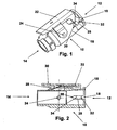
- the cable end serves to connect the coaxial connector 10 to an RF transmission line, such as a coaxial cable.
- a locking fork 22 is pivotally mounted about a pivot axis 24.
- the latching fork 22 comprises two latching prongs 26, one of which covers an axial slot 18 tangentially between the plug-side end 12 and the stopper 20 when the latching fork 22 in the in Fig. 1 and 2 is shown locking position.
- a leaf spring 28 acts on the latching fork 22 with an elastic spring force such that the latching fork 22 is pressed into the locking position.
- the locking fork 22 Upon pressure on the locking fork 22 at the point indicated by arrow 30, the locking fork 22 is pivoted about the pivot axis 24 in a release position (not shown) in which the locking prongs 26, the axial slots 18 no longer cover, so that the axial slots 18th are freely continuous in the axial direction.
- Each locking prongs 26 has at a plug-side end 12 of the coaxial connector 10 side facing a first inclined surface 32 such that seen in the locking position of the locking fork 22 in the direction of the plug-side end 12 of the coaxial connector 10 to the cable end 14 of the coaxial connector 10, the tangential Covering of the axial slot 18 by the locking prongs 26 increases, in particular from Fig. 2 seen.
- Each locking prongs 26 has on a side facing the cable end 14 of the coaxial connector 10 a second inclined surface 34 such that seen in the locking position of the locking fork 22 in the direction of the plug-side end 12 of the coaxial connector 10 to the cable-side end 14 of the coaxial connector 10, the tangential Covering of the axial slot 18 by the locking prongs 26 decreases, as in particular Fig. 2 seen.
- the 3 and 4 illustrate the coaxial connector 10 according to the invention in a plugged onto a BNC coaxial socket 36 state.
- This BNC coaxial socket 36 includes two BNC pins 38, which are originally for a known bayonet lock a suitably designed BNC connector with bayonet rotary sleeve, as is common with BNC connectors.
- the axial slots 18 engage over the BNC pins 38, so that the coaxial connector 10 according to the invention only in a certain position relative to the BNC coaxial socket 36 this can be plugged.
- the BNC pins 38 cooperating with the coaxial slots 18 additionally form a guide and an anti-twist device.
- the BNC pins 38 which project beyond the housing 16 in the radial direction, first slide along the first inclined surfaces 32 of the latching prongs 26 and thereby push or pivot the latching fork 22 counter to elastic spring force of the leaf spring 28 from the locking position to the release position. Thereby, the axial slots 18 are released and the BNC pins 38 can be further inserted in and along the axial slots 18 up to the respective stops 20 in the axial direction.
- the BNC pins 38 leave the region of the first inclined surfaces 32 and the locking fork 22 pivots under the elastic spring force of the leaf spring 28 back into the locking position.
- the BNC pins 38 are locked between the stops 20 and the locking prongs 26 and can not be pulled out of the axial slots 18 in the direction of arrow 40 again.
- the coaxial connector 10 and the BNC coaxial connector 36 are fixedly connected to each other.
- the second inclined surfaces 34 of the locking prongs 26 press on the BNC pins 38 under the action of the elastic spring force of the leaf spring 28, so that they are pressed in the direction or against the stops 20 or against the direction of arrow 40. This produces a corresponding contact pressure for establishing electrical contact between the coaxial connector 10 and the BNC coaxial connector 36.
- the mechanical and electrical connection of the coaxial connector 10 to the BNC coaxial connector 36 is made by simply attaching the coaxial connector 10 to the BNC coaxial connector 36 in the insertion direction 40 to the BNC pins 38 strike the attacks 20.
- the locking connection between coaxial connector 10 and BNC coaxial socket 36 is thereby automatically produced by the locking fork 22.
- a pressure is manually exerted on the locking fork 22 at arrow 30, so that the locking fork 22 is pivoted against the elastic spring force of the leaf spring 28 in the release position about the pivot axis 24.
Landscapes
- Details Of Connecting Devices For Male And Female Coupling (AREA)
- Coupling Device And Connection With Printed Circuit (AREA)
Description
- Die vorliegende Erfindung betrifft einen Koaxialstecker mit einem Gehäuse, einem steckseitigen Ende zum Verbinden mit einer BNC-Koaxialbuchse, welche zwei BNC-Stifte eines Bajonettverschlusses aufweist, und einem kabelseitigen Ende zum Verbinden mit einer HF-Übertragungsleitung, insbesondere einem Koaxialkabel, gemäß dem Oberbegriff des Anspruchs 1, wie in
US-A-2005/0037652 offenbart. - Beispielsweise zum Verbinden eines Tastkopfes mit einem Messgerät, wie beispielsweise einem Oszilloskop, ist es bekannt, dass an dem Messgerät BNC-Koaxialbuchsen (BNC = Bajonett Navi Connector) angeordnet sind, auf die jeweils ein entsprechender BNC-Koaxialstecker des Tastkopfes aufsteckbar ist. Häufig werden jedoch zusätzliche elektrische Verbindungsleitungen zwischen dem Tastkopf und dem Messgerät benötigt, um beispielsweise weitere Signale oder eine Versorgungsspannung für den Tastkopf zu übertragen. Da es eine Eigenart der BNC-Steckverbindung mit Bajonettverschluss ist, dass der BNC-Koaxialstecker frei relativ zur BNC-Koaxialbuchse verdrehbar ist, können diese zusätzlichen Verbindungsleitungen zunächst nicht durch die BNC-Steckverbindung hergestellt werden. Um dieses Problem zu umgehen und zusätzliche Verbindungsleitungen zwischen Tastkopf und Messgerät beispielsweise über an BNC-Koaxialbuchse und BNC-Koaxialstecker angeordnete Kontaktpins herzustellen, ist es bereits bekannt, einen Formschluss zwischen einem Gehäuse des Messgerätes und einem Gehäuse des BNC-Koaxialsteckers des Tastkopfes vorzusehen. Dadurch ist der BNC-Koaxialstecker nur noch in einer bestimmten Orientierung relativ zur BNC-Koaxialbuchse auf diese Aufsteckbar, so dass die richtigen Kontaktpins von BNC-Koaxialstecker und BNC-Koaxialbuchse miteinander funktionssicher in Kontakt kommen. Dies ist jedoch aufwändig und bedingt, dass Messgerät und Tastkopf hinsichtlich deren Gehäuseausformung individuell aufeinander abgestimmt sein müssen. Mit anderen Worten sind Tastköpfe unterschiedlicher Hersteller nicht mit allen Messgeräten unterschiedlicher Hersteller kompatibel.
- Der Erfindung liegt die Aufgabe zugrunde, einen Koaxialstecker der o.g. Art derart auszugestalten, dass unabhängig von der Form des Gehäuses des Koaxialsteckers eine verdrehsichere Steckverbindung mit einer BNC-Koaxialbuchse und mit vorbestimmter Orientierung relativ zu dieser BNC-Koaxialbuchse herstellbar ist.
- Diese Aufgabe wird erfindungsgemäß durch einen Koaxialstecker der o.g. Art mit den in Anspruch 1 gekennzeichneten Merkmalen gelöst. Vorteilhafte Ausgestaltungen der Erfindung sind in den weiteren Ansprüchen beschrieben.
- Bei einem Koaxialstecker der o.g. Art ist es erfindungsgemäß vorgesehen, dass das Gehäuse des Koaxialsteckers zwei gegenüberliegend angeordnete, ausgehend von dem steckseitigen Ende des Koaxialsteckers in axialer Richtung verlaufende Schlitze aufweist, welche jeweils zur Aufnahme eines BNC-Stiftes derart angeordnet und ausgebildet sind, dass diese jeweils einen axialen Anschlag für einen BNC-Stift ausbilden, wobei an dem Gehäuse des Koaxialsteckers eine Rastgabel angeordnet ist, die zwei Rastzinken aufweist, wobei jeder Rastzinken einen axialen Schlitz des Gehäuses des Koaxialsteckers zwischen dem Anschlag und dem steckseitigen Ende des Koaxialsteckers tangential derart übergreift, dass bei auf die BNC-Koaxialbuchse aufgestecktem Koaxialstecker jeweils ein BNC-Stift zwischen einem Rastzinken und einem Anschlag des axialen Schlitzes festgehalten ist und eine verriegelte Verbindung zwischen dem Koaxialstecker und der BNC-Koaxialbuchse herstellt, wobei die Rastgabel schwenkbar an dem Gehäuse des Koaxialsteckers angeordnet und zwischen einer Verriegelungsposition, in der die Rastzinken die axialen Schlitze tangential überdecken, und einer Freigabeposition, in der die Rastzinken die axialen Schlitze über deren gesamte Länge frei geben, so dass die BNC-Stifte in die axialen Schlitze in axialer Richtung einsteckbar oder aus diesen in axialer Richtung herausziehbar sind, verschwenkbar ist.
- Dies hat den Vorteil, dass ein an sich bzgl. einer Drehhülse für einen Bajonettverschluss nicht dem BNC-Standard entsprechender Koaxialstecker funktionssicher mit einer BNC-Buchse verbindbar ist, wobei gleichzeitig durch die axialen Schlitze eine vorbestimmte Orientierung zwischen Koaxialstecker und BNC-Koaxialbuchse sowie eine Sicherung gegen ein Verdrehen des Koaxialsteckers relativ zur BNC-Koaxialbuchse gewährleitstet ist. Die axialen Schlitze bilden zusammenwirkend mit den BNC-Stiften eine Führung für den Koaxialstecker beim axialen Aufschieben auf die BNC-Buchse aus und begrenzen mit dem Anschlag die axiale Einschubtiefe. Zusätzlich ist zum Verriegeln die Rastgabel vorhanden, so dass statt einer Drehbewegung zum Verriegeln eines Bajonettverschlusses lediglich die Rastgabel in die Verriegelungsposition verschwenkt werden muss, um eine fest verriegelte Verbindung zwischen dem Koaxialstecker und der BNC-Buchse herzustellen.
- Ein automatisches Verrasten des Koaxialsteckers an der BNC-Koaxialbuchse mittels der Rastgabel wird dadurch erzielt, dass die Rastgabel in Richtung der Verriegelungsposition mit einer elastischen Federkraft beaufschlagt ist. Hierdurch erfolgt das verrastende Verbinden des Koaxialsteckers mit der BNC-Koaxialbuchse durch einfaches manuelles Aufschieben des Koaxialsteckers auf die BNC-Koaxialbuchse, wobei ohne zusätzliche manuelle Tätigkeiten die Verriegelung der Rastgabel an den BNC-Stiften einrastet.
- In einer bevorzugten Ausführungsform sind die axialen Schlitze derart ausgebildet, dass die BNC-Stifte das Gehäuse radial nach außen überragen.
- Dadurch, dass jeder Rastzinken an einer dem steckseitigen Ende des Koaxialsteckers zugewanden Seite eine erste schräge Fläche derart aufweist, dass in der Verriegelungsposition der Rastgabel in Richtung von dem steckseitigen Ende des Koaxialsteckers zum kabelseitigen Ende des Koaxialsteckers gesehen die tangentiale Überdeckung des axialen Schlitzes durch den Rastzinken zunimmt, wird beim Aufstecken des Koaxialsteckers auf die BNC-Buchse die Rastgabel von den BNC-Stiften automatisch in die Freigabeposition verschwenkt.
- Eine zusätzliche Kontaktkraft bei mit der BNC-Koaxialbuchse verriegeltem Koaxialstecker, welche die BNC-Koaxialbuchse axial in den Koaxialstecker zieht, oder umgekehrt, erzielt man dadurch, dass jeder Rastzinken an einer von dem kabelseitigen Ende des Koaxialsteckers zugewandten Seite eine zweite schräge Fläche derart aufweist, dass in der Verriegelungsposition der Rastgabel in Richtung von dem steckseitigen Ende des Koaxialsteckers zum kabelseitigen Ende des Koaxialsteckers gesehen die tangentiale Überdeckung des axialen Schlitzes durch den Rastzinken abnimmt.
- Die Erfindung wird im Folgenden anhand der Zeichnung näher erläutert. Diese zeigt in:
- Fig. 1
- eine bevorzugte Ausführungsform eines erfindungsgemäßen Koaxialsteckers in perspektivischer Ansicht,
- Fig. 2
- den Koaxialstecker gemäß
Fig. 1 in Schnittansicht, - Fig. 3
- den Koaxialstecker gemäß
Fig. 1 in auf eine BNC-Koaxialbuchse aufgestecktem Zustand in perspektivischer Ansicht und - Fig. 4
- in Seitenansicht.
- Die in
Fig. 1 und 2 dargestellte, bevorzugte Ausführungsform eines erfindungsgemäßen Koaxialsteckers 10 mit einem steckseitigen Ende 12 und einem kabelseitigen Ende 14 umfasst ein Gehäuse 16 in dem zwei gegenüberliegende, axiale Schlitze 18 ausgebildet sind, die sich ausgehend von dem steckseitigen Ende 12 in axialer Richtung erstrecken. Jeder axiale Schlitz 18 endet mit einem Anschlag 20. Das kabelseitige Ende dient zum Verbinden des Koaxialsteckers 10 mit einer HF-Übertragungsleitung, wie beispielsweise einem Koaxialkabel. An dem Gehäuse 16 ist eine Rastgabel 22 schwenkbar um eine Schwenkachse 24 angeordnet. Die Rastgabel 22 umfasst zwei Rastzinken 26, von denen jeweils eine einen axialen Schlitz 18 tangential zwischen dem steckseitigen Ende 12 und dem Anschlag 20 überdeckt, wenn sich die Rastgabel 22 in der inFig. 1 und 2 dargestellten Verriegelungsposition befindet. Eine Blattfeder 28 beaufschlagt die Rastgabel 22 derart mit einer elastischen Federkraft, dass die Rastgabel 22 in die Verriegelungsposition gedrückt wird. - Bei Druck auf die Rastgabel 22 an der mit Pfeil 30 gekennzeichneten Stelle, wird die Rastgabel 22 um die Schwenkachse 24 in eine Freigabeposition (nicht dargestellt) verschwenkt, in der die Rastzinken 26 die axialen Schlitze 18 nicht mehr überdecken, so dass die axialen Schlitze 18 in axialer Richtung frei durchgängig sind.
- Jeder Rastzinken 26 weist an einer dem steckseitigen Ende 12 des Koaxialsteckers 10 zugewandten Seite eine erste schräge Fläche 32 derart auf, dass in der Verriegelungsposition der Rastgabel 22 in Richtung von dem steckseitigen Ende 12 des Koaxialsteckers 10 zum kabelseitigen Ende 14 des Koaxialsteckers 10 gesehen die tangentiale Überdeckung des axialen Schlitzes 18 durch den Rastzinken 26 zunimmt, wie insbesondere aus
Fig. 2 ersichtlich. Jeder Rastzinken 26 weist an einer dem kabelseitigen Ende 14 des Koaxialsteckers 10 zugewandten Seite eine zweite schräge Fläche 34 derart auf, dass in der Verriegelungsposition der Rastgabel 22 in Richtung von dem steckseitigen Ende 12 des Koaxialsteckers 10 zum kabelseitigen Ende 14 des Koaxialsteckers 10 gesehen die tangentiale Überdeckung des axialen Schlitzes 18 durch den Rastzinken 26 abnimmt, wie insbesondere ausFig. 2 ersichtlich. - Die
Fig. 3 und 4 veranschaulichen den erfindungsgemäßen Koaxialstecker 10 in auf eine BNC-Koaxialbuchse 36 aufgestecktem Zustand. Diese BNC-Koaxialbuchse 36 umfasst zwei BNC-Stifte 38, die originär für einen bekannten Bajonettverschluss eines entsprechend ausgebildeten BNC-Steckers mit Bajonett-Drehhülse dienen, wie dies bei BNC-Steckverbindern üblich ist. Beim Aufschieben des erfindungsgemäßen Koaxialsteckers 10 auf die BNC-Koaxialbuchse 36 in axialer Richtung bzw. in Einsteckrichtung 40 greifen die axialen Schlitze 18 über die BNC-Stifte 38, so dass der erfindungsgemäße Koaxialstecker 10 nur in einer bestimmten Position relativ zur BNC-Koaxialbuchse 36 auf diese aufgesteckt werden kann. Die BNC-Stifte 38 bilden zusammenwirkend mit den koaxialen Schlitzen 18 zusätzlich eine Führung sowie eine Verdrehsicherung aus. Beim axialen Aufstecken des erfindungsgemäßen Koaxialsteckers 10 auf die BNC-Koaxialbuchse 36 gleiten die BNC-Stifte 38, welche in radialer Richtung das Gehäuse 16 überragen, zunächst entlang der ersten schrägen Flächen 32 der Rastzinken 26 und drücken bzw. verschwenken dadurch die Rastgabel 22 entgegen der elastischen Federkraft der Blattfeder 28 aus der Verriegelungsposition in die Freigabeposition. Dadurch werden die axialen Schlitze 18 frei gegeben und die BNC-Stifte 38 können in den und entlang der axialen Schlitze 18 bis zu den jeweiligen Anschlägen 20 weiter in axialer Richtung eingeschoben werden. Dabei verlassen die BNC-Stifte 38 den Bereich der ersten schrägen Flächen 32 und die Rastgabel 22 schwenkt unter der elastischen Federkraft der Blattfeder 28 zurück in die Verriegelungsposition. Dadurch sind die BNC-Stifte 38 zwischen den Anschlägen 20 und den Rastzinken 26 verriegelt und können nicht wieder aus den axialen Schlitzen 18 in Richtung von Pfeil 40 heraus gezogen werden. Somit sind der Koaxialstecker 10 und die BNC-Koaxialbuchse 36 miteinander fest verbunden. Die zweiten schrägen Flächen 34 der Rastzinken 26 drücken unter Einwirkung der elastischen Federkraft der Blattfeder 28 auf die BNC-Stifte 38, so dass diese in Richtung bzw. gegen die Anschläge 20 bzw. entgegen der Richtung von Pfeil 40 gedrückt werden. Dies erzeugt einen entsprechenden Kontaktdruck zur Herstellung eines elektrischen Kontaktes zwischen dem Koaxialstecker 10 und der BNC-Koaxialbuchse 36. - Im Ergebnis erfolgt das mechanische und elektrische Verbinden des Koaxialsteckers 10 mit der BNC-Koaxialbuchse 36 durch einfaches Aufstecken des Koaxialsteckers 10 auf die BNC-Koaxialbuchse 36 in Einsteckrichtung 40 bis die BNC-Stifte 38 an den Anschlägen 20 anschlagen. Die verriegelnde Verbindung zwischen Koaxialstecker 10 und BNC-Koaxialbuchse 36 wird dabei durch die Rastgabel 22 automatisch hergestellt. Zum Lösen des Koaxialsteckers 10 von der BNC-Koaxialbuchse 36 wird auf die Rastgabel 22 bei Pfeil 30 manuell ein Druck ausgeübt, so dass die Rastgabel 22 entgegen der elastischen Federkraft der Blattfeder 28 in die Freigabeposition um die Schwenkachse 24 verschwenkt. Dadurch ist der Weg für die BNC-Stifte 38 aus den axialen Schlitzen 18 heraus in Richtung von Pfeil 40 nicht mehr durch die Rastzinken 26 blockiert, so dass der Koaxialstecker 10 von der BNC-Koaxialbuchse 36 in Richtung entgegen der Einsteckrichtung 40 abgezogen werden kann.
Claims (5)
- Koaxialstecker (10) mit einem Gehäuse (16), einem steckseitigen Ende (12) zum Verbinden mit einer BNC-Koaxialbuchse (36), welche zwei BNC-Stifte (38) eines Bajonettverschlusses aufweist, und einem kabelseitigen Ende (14) zum Verbinden mit einer HF-Übertragungsleitung, insbesondere einem Koaxialkabel,
dadurch gekennzeichnet,
dass das Gehäuse (16) des Koaxialsteckers (10) zwei gegenüberliegend angeordnete, ausgehend von dem steckseitigen Ende (12) des Koaxialsteckers (10) in axialer Richtung verlaufende Schlitze (18) aufweist, welche jeweils zur Aufnahme eines BNC-Stiftes (38) derart angeordnet und ausgebildet sind, dass diese jeweils einen axialen Anschlag (20) für einen BNC-Stift (38) ausbilden, wobei an dem Gehäuse (16) des Koaxialsteckers (10) eine Rastgabel (22) angeordnet ist, die zwei Rastzinken (26) aufweist, wobei jeder Rastzinken (26) einen axialen Schlitz (18) des Gehäuses (16) des Koaxialsteckers (10) zwischen dem Anschlag (20) und dem steckseitigen Ende (12) des Koaxialsteckers (10) tangential derart übergreift, dass bei auf die BNC-Koaxialbuchse (36) aufgestecktem Koaxialstecker (10) jeweils ein BNC-Stift (38) zwischen einem Rastzinken (26) und einem Anschlag (20) des axialen Schlitzes (18) festgehalten ist und eine verriegelte Verbindung zwischen dem Koaxialstecker (10) und der BNC-Koaxialbuchse (36) herstellt, wobei die Rastgabel (22) schwenkbar an dem Gehäuse (16) des Koaxialsteckers (10) angeordnet und zwischen einer Verriegelungsposition, in der die Rastzinken (26) die axialen Schlitze (18) tangential überdecken, und einer Freigabeposition, in der die Rastzinken (26) die axialen Schlitze (18) über deren gesamte Länge frei geben, so dass die BNC-Stifte (38) in die axialen Schlitze (18) in axialer Richtung einsteckbar oder aus diesen in axialer Richtung herausziehbar sind, verschwenkbar ist. - Koaxialstecker (10) nach Anspruch 1, dadurch gekennzeichnet, dass die Rastgabel (22) in Richtung der Verriegelungsposition mit einer elastischen Federkraft beaufschlagt ist.
- Koaxialstecker (10) nach Anspruch 1 oder 2, dadurch gekennzeichnet, dass die axialen Schlitze (18) derart ausgebildet sind, dass die BNC-Stifte (38) das Gehäuse (16) radial nach außen überragen.
- Koaxialstecker (10) nach wenigstens einem der vorhergehenden Ansprüche, dadurch gekennzeichnet, dass jeder Rastzinken (26) an einer dem steckseitigen Ende (12) des Koaxialsteckers (10) zugewandten Seite eine erste schräge Fläche (32) derart aufweist, dass in der Verriegelungsposition der Rastgabel (22) in Richtung von dem steckseitigen Ende (12) des Koaxialsteckers (10) zum kabelseitigen Ende (14) des Koaxialsteckers (10) gesehen die tangentiale Überdeckung des axialen Schlitzes (18) durch den Rastzinken (26) zunimmt.
- Koaxialstecker nach wenigstens einem der vorhergehenden Ansprüche, dadurch gekennzeichnet, dass jeder Rastzinken (26) an einer von dem kabelseitigen Ende (14) des Koaxialsteckers (10) zugewandten Seite eine zweite schräge Fläche (34) derart aufweist, dass in der Verriegelungsposition der Rastgabel (22) in Richtung von dem steckseitigen Ende (12) des Koaxialsteckers (10) zum kabelseitigen Ende (14) des Koaxialsteckers (10) gesehen die tangentiale Überdeckung des axialen Schlitzes (18) durch den Rastzinken (26) abnimmt.
Applications Claiming Priority (2)
| Application Number | Priority Date | Filing Date | Title |
|---|---|---|---|
| DE202006019203U DE202006019203U1 (de) | 2006-12-20 | 2006-12-20 | Koaxialstecker zum Verbinden mit einer BNC-Koaxialbuchse |
| PCT/EP2007/010623 WO2008080501A1 (de) | 2006-12-20 | 2007-12-06 | Koaxialstecker zum verbinden mit einer bnc-koaxialbuchse |
Publications (2)
| Publication Number | Publication Date |
|---|---|
| EP2092614A1 EP2092614A1 (de) | 2009-08-26 |
| EP2092614B1 true EP2092614B1 (de) | 2010-04-28 |
Family
ID=37833217
Family Applications (1)
| Application Number | Title | Priority Date | Filing Date |
|---|---|---|---|
| EP07856428A Active EP2092614B1 (de) | 2006-12-20 | 2007-12-06 | Koaxialstecker zum verbinden mit einer bnc-koaxialbuchse |
Country Status (6)
| Country | Link |
|---|---|
| US (1) | US7905742B2 (de) |
| EP (1) | EP2092614B1 (de) |
| CN (1) | CN101595605B (de) |
| AT (1) | ATE466390T1 (de) |
| DE (2) | DE202006019203U1 (de) |
| WO (1) | WO2008080501A1 (de) |
Families Citing this family (6)
| Publication number | Priority date | Publication date | Assignee | Title |
|---|---|---|---|---|
| JP5466025B2 (ja) * | 2010-01-22 | 2014-04-09 | 矢崎総業株式会社 | 嵌合補助治具及びこれを用いたコネクタ |
| US9052473B2 (en) | 2012-11-02 | 2015-06-09 | Samtec, Inc. | Pivoting latch for cable housing |
| US9618704B2 (en) * | 2013-07-31 | 2017-04-11 | Corning Optical Communications LLC | Fiber optic connector sub-assemblies having a front-loading locking ferrule holder and related fiber optic components, devices and methods |
| US9577377B1 (en) * | 2016-01-11 | 2017-02-21 | Sumitomo Wiring Systems, Ltd. | Connector assembly with lever and shroud |
| DE102019125827A1 (de) * | 2019-09-25 | 2021-03-25 | Endress+Hauser Flowtec Ag | Elektrischer Verbinder und Feldgerät der Mess-/Automatisierungstechnik |
| GB2603965A (en) * | 2021-02-23 | 2022-08-24 | Cambridge Electronic Ind Ltd | Locking connector |
Family Cites Families (8)
| Publication number | Priority date | Publication date | Assignee | Title |
|---|---|---|---|---|
| JP2500247Y2 (ja) * | 1991-06-03 | 1996-06-05 | 矢崎総業株式会社 | レバ―付コネクタ |
| JP2762896B2 (ja) * | 1993-06-14 | 1998-06-04 | 住友電装株式会社 | レバー式コネクタ |
| JP3000129B2 (ja) * | 1994-09-06 | 2000-01-17 | 矢崎総業株式会社 | レバー式コネクタ |
| US5823808A (en) * | 1996-08-20 | 1998-10-20 | Chrysler Corporation | Cam lever operated connector |
| DE19923386C1 (de) | 1999-05-21 | 2001-01-18 | Framatome Connectors Int | Elektrischer Steckverbinder, insbesondere für Kraftfahrzeuganwendungen |
| JP3538750B2 (ja) * | 1999-08-02 | 2004-06-14 | 住友電装株式会社 | レバー式コネクタ |
| JP2001237026A (ja) * | 2000-02-23 | 2001-08-31 | Yazaki Corp | レバー付コネクタ |
| US6921283B2 (en) * | 2001-08-27 | 2005-07-26 | Trompeter Electronics, Inc. | BNC connector having visual indication |
-
2006
- 2006-12-20 DE DE202006019203U patent/DE202006019203U1/de not_active Expired - Lifetime
-
2007
- 2007-12-06 WO PCT/EP2007/010623 patent/WO2008080501A1/de not_active Ceased
- 2007-12-06 US US12/520,367 patent/US7905742B2/en active Active
- 2007-12-06 EP EP07856428A patent/EP2092614B1/de active Active
- 2007-12-06 DE DE502007003629T patent/DE502007003629D1/de active Active
- 2007-12-06 CN CN2007800470293A patent/CN101595605B/zh active Active
- 2007-12-06 AT AT07856428T patent/ATE466390T1/de active
Also Published As
| Publication number | Publication date |
|---|---|
| DE202006019203U1 (de) | 2007-02-22 |
| CN101595605B (zh) | 2011-09-07 |
| HK1139511A1 (en) | 2010-09-17 |
| CN101595605A (zh) | 2009-12-02 |
| US20100105234A1 (en) | 2010-04-29 |
| WO2008080501A1 (de) | 2008-07-10 |
| EP2092614A1 (de) | 2009-08-26 |
| ATE466390T1 (de) | 2010-05-15 |
| US7905742B2 (en) | 2011-03-15 |
| DE502007003629D1 (de) | 2010-06-10 |
Similar Documents
| Publication | Publication Date | Title |
|---|---|---|
| EP1222717B1 (de) | Koaxialer steckverbinder | |
| EP1977484A1 (de) | Koaxiale steckverbinderanordnung | |
| EP1955413B1 (de) | Push-pull-koaxialsteckverbinder | |
| EP1239550B1 (de) | Steckverbinder | |
| EP1747604B1 (de) | Gehäusekuppler für einen koaxialsteckverbinder | |
| EP0772261A2 (de) | Koaxial-Steckverbindung | |
| DE1956162B2 (de) | Elektrische Steckverbindung | |
| EP4066325B1 (de) | Sekundärverriegelungsvorrichtung | |
| WO2016173698A1 (de) | Steckverbindung und satz von steckverbindungen | |
| EP4000139B1 (de) | Kontaktelement | |
| EP3109949A1 (de) | Steckverbinder und gegensteckverbinder | |
| EP2092614A1 (de) | Koaxialstecker zum verbinden mit einer bnc-koaxialbuchse | |
| DE202015001331U1 (de) | Steckverbinder mit Dämpfungselement | |
| DE102016108621B4 (de) | Steckverbindergehäuse und Steckverbinder | |
| EP4049343A1 (de) | Klemmeneinrichtung zum anschliessen eines elektrischen leiters | |
| DE102006025346B4 (de) | Steckverbindung mit einem Hebel | |
| EP1744408B1 (de) | Elektrische Steckverbindung | |
| DE202006020191U1 (de) | Steckvorrichtung nach EN 60 309 mit einem Drehkörper zur Abdichtung und Verriegelung ohne Klappdeckel | |
| EP4312322B1 (de) | Netzwerkanschlussstecker und steckverbindung | |
| DE20318593U1 (de) | Anordnung eines Elementes in einem Rundsteckverbinder | |
| DE102012111125B4 (de) | RJ45-Stecker und Steckverbinderanordnung mit Positionierungselement | |
| WO2020064804A1 (de) | Elektrischer steckverbinder | |
| DE102010028802B4 (de) | Stecker mit einem Sperrelement | |
| DE102013014202B4 (de) | Steckverbindersystem | |
| AT410616B (de) | Elektrischer kabelstecker |
Legal Events
| Date | Code | Title | Description |
|---|---|---|---|
| PUAI | Public reference made under article 153(3) epc to a published international application that has entered the european phase |
Free format text: ORIGINAL CODE: 0009012 |
|
| 17P | Request for examination filed |
Effective date: 20090526 |
|
| AK | Designated contracting states |
Kind code of ref document: A1 Designated state(s): AT BE BG CH CY CZ DE DK EE ES FI FR GB GR HU IE IS IT LI LT LU LV MC MT NL PL PT RO SE SI SK TR |
|
| RIN1 | Information on inventor provided before grant (corrected) |
Inventor name: WOLLITZER, MICHAEL Inventor name: REICHEL, THOMAS Inventor name: KOENIG, HANS-DIETER Inventor name: HAGENBUSCH, RALF Inventor name: TATZEL, FRANK Inventor name: PESCHKE, MARTIN Inventor name: ULLRICH, STEFAN Inventor name: BABINGER, HERBERT Inventor name: FUEHRICH, MANUELA |
|
| RIN1 | Information on inventor provided before grant (corrected) |
Inventor name: FUEHRICH, MANUELA Inventor name: WOLLITZER, MICHAEL Inventor name: ULLRICH, STEFAN Inventor name: HAGENBUSCH, RALF Inventor name: BABINGER, HERBERT Inventor name: KOENIG, HANS-DIETER Inventor name: TATZEL, FRANK Inventor name: PESCHKE, MARTIN Inventor name: REICHEL, THOMAS |
|
| GRAP | Despatch of communication of intention to grant a patent |
Free format text: ORIGINAL CODE: EPIDOSNIGR1 |
|
| DAX | Request for extension of the european patent (deleted) | ||
| GRAS | Grant fee paid |
Free format text: ORIGINAL CODE: EPIDOSNIGR3 |
|
| GRAA | (expected) grant |
Free format text: ORIGINAL CODE: 0009210 |
|
| AK | Designated contracting states |
Kind code of ref document: B1 Designated state(s): AT BE BG CH CY CZ DE DK EE ES FI FR GB GR HU IE IS IT LI LT LU LV MC MT NL PL PT RO SE SI SK TR |
|
| REG | Reference to a national code |
Ref country code: GB Ref legal event code: FG4D Free format text: NOT ENGLISH |
|
| REG | Reference to a national code |
Ref country code: CH Ref legal event code: EP |
|
| REG | Reference to a national code |
Ref country code: IE Ref legal event code: FG4D Free format text: LANGUAGE OF EP DOCUMENT: GERMAN |
|
| REF | Corresponds to: |
Ref document number: 502007003629 Country of ref document: DE Date of ref document: 20100610 Kind code of ref document: P |
|
| REG | Reference to a national code |
Ref country code: NL Ref legal event code: VDEP Effective date: 20100428 |
|
| LTIE | Lt: invalidation of european patent or patent extension |
Effective date: 20100428 |
|
| PG25 | Lapsed in a contracting state [announced via postgrant information from national office to epo] |
Ref country code: SE Free format text: LAPSE BECAUSE OF FAILURE TO SUBMIT A TRANSLATION OF THE DESCRIPTION OR TO PAY THE FEE WITHIN THE PRESCRIBED TIME-LIMIT Effective date: 20100428 Ref country code: ES Free format text: LAPSE BECAUSE OF FAILURE TO SUBMIT A TRANSLATION OF THE DESCRIPTION OR TO PAY THE FEE WITHIN THE PRESCRIBED TIME-LIMIT Effective date: 20100808 Ref country code: LT Free format text: LAPSE BECAUSE OF FAILURE TO SUBMIT A TRANSLATION OF THE DESCRIPTION OR TO PAY THE FEE WITHIN THE PRESCRIBED TIME-LIMIT Effective date: 20100428 Ref country code: NL Free format text: LAPSE BECAUSE OF FAILURE TO SUBMIT A TRANSLATION OF THE DESCRIPTION OR TO PAY THE FEE WITHIN THE PRESCRIBED TIME-LIMIT Effective date: 20100428 |
|
| REG | Reference to a national code |
Ref country code: IE Ref legal event code: FD4D |
|
| PG25 | Lapsed in a contracting state [announced via postgrant information from national office to epo] |
Ref country code: LV Free format text: LAPSE BECAUSE OF FAILURE TO SUBMIT A TRANSLATION OF THE DESCRIPTION OR TO PAY THE FEE WITHIN THE PRESCRIBED TIME-LIMIT Effective date: 20100428 Ref country code: SI Free format text: LAPSE BECAUSE OF FAILURE TO SUBMIT A TRANSLATION OF THE DESCRIPTION OR TO PAY THE FEE WITHIN THE PRESCRIBED TIME-LIMIT Effective date: 20100428 Ref country code: FI Free format text: LAPSE BECAUSE OF FAILURE TO SUBMIT A TRANSLATION OF THE DESCRIPTION OR TO PAY THE FEE WITHIN THE PRESCRIBED TIME-LIMIT Effective date: 20100428 Ref country code: IS Free format text: LAPSE BECAUSE OF FAILURE TO SUBMIT A TRANSLATION OF THE DESCRIPTION OR TO PAY THE FEE WITHIN THE PRESCRIBED TIME-LIMIT Effective date: 20100828 |
|
| PG25 | Lapsed in a contracting state [announced via postgrant information from national office to epo] |
Ref country code: CY Free format text: LAPSE BECAUSE OF FAILURE TO SUBMIT A TRANSLATION OF THE DESCRIPTION OR TO PAY THE FEE WITHIN THE PRESCRIBED TIME-LIMIT Effective date: 20100616 Ref country code: PL Free format text: LAPSE BECAUSE OF FAILURE TO SUBMIT A TRANSLATION OF THE DESCRIPTION OR TO PAY THE FEE WITHIN THE PRESCRIBED TIME-LIMIT Effective date: 20100428 |
|
| PG25 | Lapsed in a contracting state [announced via postgrant information from national office to epo] |
Ref country code: PT Free format text: LAPSE BECAUSE OF FAILURE TO SUBMIT A TRANSLATION OF THE DESCRIPTION OR TO PAY THE FEE WITHIN THE PRESCRIBED TIME-LIMIT Effective date: 20100830 Ref country code: DK Free format text: LAPSE BECAUSE OF FAILURE TO SUBMIT A TRANSLATION OF THE DESCRIPTION OR TO PAY THE FEE WITHIN THE PRESCRIBED TIME-LIMIT Effective date: 20100428 Ref country code: IE Free format text: LAPSE BECAUSE OF FAILURE TO SUBMIT A TRANSLATION OF THE DESCRIPTION OR TO PAY THE FEE WITHIN THE PRESCRIBED TIME-LIMIT Effective date: 20100428 Ref country code: EE Free format text: LAPSE BECAUSE OF FAILURE TO SUBMIT A TRANSLATION OF THE DESCRIPTION OR TO PAY THE FEE WITHIN THE PRESCRIBED TIME-LIMIT Effective date: 20100428 |
|
| PG25 | Lapsed in a contracting state [announced via postgrant information from national office to epo] |
Ref country code: CZ Free format text: LAPSE BECAUSE OF FAILURE TO SUBMIT A TRANSLATION OF THE DESCRIPTION OR TO PAY THE FEE WITHIN THE PRESCRIBED TIME-LIMIT Effective date: 20100428 Ref country code: RO Free format text: LAPSE BECAUSE OF FAILURE TO SUBMIT A TRANSLATION OF THE DESCRIPTION OR TO PAY THE FEE WITHIN THE PRESCRIBED TIME-LIMIT Effective date: 20100428 Ref country code: SK Free format text: LAPSE BECAUSE OF FAILURE TO SUBMIT A TRANSLATION OF THE DESCRIPTION OR TO PAY THE FEE WITHIN THE PRESCRIBED TIME-LIMIT Effective date: 20100428 |
|
| PLBE | No opposition filed within time limit |
Free format text: ORIGINAL CODE: 0009261 |
|
| STAA | Information on the status of an ep patent application or granted ep patent |
Free format text: STATUS: NO OPPOSITION FILED WITHIN TIME LIMIT |
|
| PG25 | Lapsed in a contracting state [announced via postgrant information from national office to epo] |
Ref country code: IT Free format text: LAPSE BECAUSE OF FAILURE TO SUBMIT A TRANSLATION OF THE DESCRIPTION OR TO PAY THE FEE WITHIN THE PRESCRIBED TIME-LIMIT Effective date: 20100428 |
|
| 26N | No opposition filed |
Effective date: 20110131 |
|
| PG25 | Lapsed in a contracting state [announced via postgrant information from national office to epo] |
Ref country code: GR Free format text: LAPSE BECAUSE OF FAILURE TO SUBMIT A TRANSLATION OF THE DESCRIPTION OR TO PAY THE FEE WITHIN THE PRESCRIBED TIME-LIMIT Effective date: 20100729 |
|
| BERE | Be: lapsed |
Owner name: ROSENBERGER HOCHFREQUENZTECHNIK G.M.B.H. & CO. KG Effective date: 20101231 Owner name: ROHDE & SCHWARZ G.M.B.H. & CO. KG Effective date: 20101231 |
|
| PG25 | Lapsed in a contracting state [announced via postgrant information from national office to epo] |
Ref country code: MC Free format text: LAPSE BECAUSE OF NON-PAYMENT OF DUE FEES Effective date: 20101231 |
|
| PG25 | Lapsed in a contracting state [announced via postgrant information from national office to epo] |
Ref country code: BE Free format text: LAPSE BECAUSE OF NON-PAYMENT OF DUE FEES Effective date: 20101231 |
|
| PG25 | Lapsed in a contracting state [announced via postgrant information from national office to epo] |
Ref country code: MT Free format text: LAPSE BECAUSE OF FAILURE TO SUBMIT A TRANSLATION OF THE DESCRIPTION OR TO PAY THE FEE WITHIN THE PRESCRIBED TIME-LIMIT Effective date: 20100428 |
|
| REG | Reference to a national code |
Ref country code: CH Ref legal event code: PL |
|
| PG25 | Lapsed in a contracting state [announced via postgrant information from national office to epo] |
Ref country code: LU Free format text: LAPSE BECAUSE OF NON-PAYMENT OF DUE FEES Effective date: 20101206 Ref country code: BG Free format text: LAPSE BECAUSE OF FAILURE TO SUBMIT A TRANSLATION OF THE DESCRIPTION OR TO PAY THE FEE WITHIN THE PRESCRIBED TIME-LIMIT Effective date: 20100428 Ref country code: HU Free format text: LAPSE BECAUSE OF FAILURE TO SUBMIT A TRANSLATION OF THE DESCRIPTION OR TO PAY THE FEE WITHIN THE PRESCRIBED TIME-LIMIT Effective date: 20101029 |
|
| PG25 | Lapsed in a contracting state [announced via postgrant information from national office to epo] |
Ref country code: CH Free format text: LAPSE BECAUSE OF NON-PAYMENT OF DUE FEES Effective date: 20111231 Ref country code: TR Free format text: LAPSE BECAUSE OF FAILURE TO SUBMIT A TRANSLATION OF THE DESCRIPTION OR TO PAY THE FEE WITHIN THE PRESCRIBED TIME-LIMIT Effective date: 20100428 Ref country code: LI Free format text: LAPSE BECAUSE OF NON-PAYMENT OF DUE FEES Effective date: 20111231 |
|
| PG25 | Lapsed in a contracting state [announced via postgrant information from national office to epo] |
Ref country code: BG Free format text: LAPSE BECAUSE OF FAILURE TO SUBMIT A TRANSLATION OF THE DESCRIPTION OR TO PAY THE FEE WITHIN THE PRESCRIBED TIME-LIMIT Effective date: 20100728 |
|
| REG | Reference to a national code |
Ref country code: AT Ref legal event code: MM01 Ref document number: 466390 Country of ref document: AT Kind code of ref document: T Effective date: 20121206 |
|
| PG25 | Lapsed in a contracting state [announced via postgrant information from national office to epo] |
Ref country code: AT Free format text: LAPSE BECAUSE OF NON-PAYMENT OF DUE FEES Effective date: 20121206 |
|
| REG | Reference to a national code |
Ref country code: FR Ref legal event code: PLFP Year of fee payment: 9 |
|
| REG | Reference to a national code |
Ref country code: FR Ref legal event code: PLFP Year of fee payment: 10 |
|
| REG | Reference to a national code |
Ref country code: FR Ref legal event code: PLFP Year of fee payment: 11 |
|
| P01 | Opt-out of the competence of the unified patent court (upc) registered |
Effective date: 20230526 |
|
| REG | Reference to a national code |
Ref country code: DE Ref legal event code: R082 Ref document number: 502007003629 Country of ref document: DE Representative=s name: KANDLBINDER, MARKUS, DIPL.-PHYS., DE |
|
| PGFP | Annual fee paid to national office [announced via postgrant information from national office to epo] |
Ref country code: GB Payment date: 20251229 Year of fee payment: 19 |
|
| PGFP | Annual fee paid to national office [announced via postgrant information from national office to epo] |
Ref country code: FR Payment date: 20251230 Year of fee payment: 19 |
|
| PGFP | Annual fee paid to national office [announced via postgrant information from national office to epo] |
Ref country code: DE Payment date: 20260223 Year of fee payment: 19 |