EP2092397B1 - Signal isolation unit for a dual-conductor process control loop - Google Patents
Signal isolation unit for a dual-conductor process control loop Download PDFInfo
- Publication number
- EP2092397B1 EP2092397B1 EP07847177A EP07847177A EP2092397B1 EP 2092397 B1 EP2092397 B1 EP 2092397B1 EP 07847177 A EP07847177 A EP 07847177A EP 07847177 A EP07847177 A EP 07847177A EP 2092397 B1 EP2092397 B1 EP 2092397B1
- Authority
- EP
- European Patent Office
- Prior art keywords
- unit
- control loop
- process control
- current
- signal
- Prior art date
- Legal status (The legal status is an assumption and is not a legal conclusion. Google has not performed a legal analysis and makes no representation as to the accuracy of the status listed.)
- Not-in-force
Links
Images

Classifications
-
- G—PHYSICS
- G05—CONTROLLING; REGULATING
- G05B—CONTROL OR REGULATING SYSTEMS IN GENERAL; FUNCTIONAL ELEMENTS OF SUCH SYSTEMS; MONITORING OR TESTING ARRANGEMENTS FOR SUCH SYSTEMS OR ELEMENTS
- G05B19/00—Programme-control systems
- G05B19/02—Programme-control systems electric
- G05B19/04—Programme control other than numerical control, i.e. in sequence controllers or logic controllers
- G05B19/05—Programmable logic controllers, e.g. simulating logic interconnections of signals according to ladder diagrams or function charts
-
- G—PHYSICS
- G08—SIGNALLING
- G08C—TRANSMISSION SYSTEMS FOR MEASURED VALUES, CONTROL OR SIMILAR SIGNALS
- G08C19/00—Electric signal transmission systems
-
- G—PHYSICS
- G05—CONTROLLING; REGULATING
- G05B—CONTROL OR REGULATING SYSTEMS IN GENERAL; FUNCTIONAL ELEMENTS OF SUCH SYSTEMS; MONITORING OR TESTING ARRANGEMENTS FOR SUCH SYSTEMS OR ELEMENTS
- G05B2219/00—Program-control systems
- G05B2219/10—Plc systems
- G05B2219/14—Plc safety
- G05B2219/14144—Galvanic isolation
Definitions
- the invention relates to a signal separation unit for a two-conductor process control loop according to the preamble of claim 1.
- field devices are often used, which are connected to a higher-level unit via a two-wire process control loop.
- Field devices are generally used to detect and / or influence process variables. Examples of such field devices are level gauges, mass flowmeters, pressure and temperature measuring devices, pH redox potential measuring devices, conductivity measuring devices, etc., which detect the corresponding process variables level, flow, pressure, temperature, pH or conductivity as sensors.
- actuators such as valves, which make it possible to change the flow of a liquid in a section of a pipeline, serve to influence process variables.
- the signal transmission between field devices and higher-level units often takes place according to the known 4-20 mA standard.
- the measured values are transmitted as 4-20 mA current signals via the two-wire process control loop to the higher-level unit.
- the measuring range of the individual sensors is linearly mapped to the 4-20 mA current signal.
- the sensors serve as transmitter for the measured values, the control unit as receiver of the measured values.
- the parent unit usually controls the process. For this purpose, the measured values of the sensors are evaluated and control signals for the actuators are generated.
- the power supply of the field devices also takes place via the 4-20 mA current signal, so that no additional supply lines are necessary.
- Corresponding monitor units are known for the sensor-near representation of sensor states and general sensor information. These monitor units are connected to the two-wire process control loop and often evaluate the digital signals (HART signals) transmitted over the two-wire process control loop. Such monitor units are usually very expensive circuitry and require a corresponding amount of energy. Therefore, a separate power supply with a corresponding cabling effort is necessary for these devices.
- the WO 2006/106055 shows a Messunformerspeirefound for the process automation technology, which serves for Einieered a transmitter and for forwarding current signals between the transmitter and a higher-level unit via a signal line, wherein in the transmitter power supply additionally arranged via a modem microcontroller and a microcontroller controlled signaling device are arranged ,
- the object of the invention is to provide a signal separation unit for a two-wire process control loop, which allows near-sensor signaling of sensor states and which requires no complicated wiring.
- the essential idea of the invention is to arrange a power supply unit in the signal separation unit in series with the two-conductor process control loop and a communication unit parallel to the two-conductor process control loop. With the power supply unit and the communication unit, a microcontroller is connected to the one Relay is connected. As a result, a sensor-near evaluation of sensor data and a corresponding signaling of sensor states is possible.
- the two-conductor process control loop is a 4-20 mA control loop.
- the communication takes place via the control loop according to the HART standard.
- a conventional HART modem can be used as the communication unit.
- the power supply unit is designed as a DC-DC converter.
- a transformer for galvanic isolation, a transformer, the current output side, a chopper and upstream of the input side, a rectifier is provided.
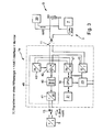
- FIG. 1 Block diagram of a signal separation unit for a two-wire process control loop according to the prior art.
- FIG. 2 Block diagram of a monitor unit for a two-wire process control loop according to the prior art.
- FIG. 3 Block diagram of a signal separation unit according to the invention.
- Signaling unit 1 shown has a transformer 40, which is preceded by a chopper 42.
- the chopper 42 is driven by an oscillator 43.
- the chopper 42 essentially consists of a switching transistor.
- Chopper 42 and oscillator 43 convert the current applied to the current input 11 into a sequence of current pulses.
- the pulsed current is transmitted via the transformer 40 and converted back into a direct current by means of a rectifier 41, which is output at the current output 13.
- Rectifier 41, transformer 40, chopper 42 and oscillator 43 form a galvanic isolator.
- a transmitter 5 which serves as a sensor, e.g. serves to detect a temperature value.
- the temperature value is transmitted to a receiver 7 as a 4-20 mA signal via the two-wire process control loop 3, in which the signal separation unit 1 is arranged.
- the receiver 7 may be, for example, a control unit SPS.
- the current signal transmitted via the two-wire process control loop 3 is supplied from a power supply unit 60.
- parameter values can be read out of the measuring transducer 5 or written to it via a HART operator device 30.
- the HART operating device 30 is briefly connected to the two-wire process control loop 3.
- signal separation unit 1 serves for a galvanic isolation of the analog current signal, which is transmitted between the sensor 5 and the receiver 7.
- the signal separation unit 1 of course also serves for galvanic isolation of the HART signals exchanged between the sensor 5 and the HART operating device 30.
- a further two-wire process control loop 3 is shown, via which also a sensor 5 (transmitter) is connected to a receiver 7.
- a monitor unit 2 is connected.
- This monitor unit 2 is supplied via a separate power supply unit 60a.
- the monitor unit 2 has a communication unit 17, which is connected to a microcontroller 19.
- To operate the monitor unit 2 is an operating unit 21, which is also connected to the microcontroller 19.
- the monitor unit 2 has a current output 70 and a relay 23.
- the power supply of the individual components via a power supply unit 15 which is connected to the individual components 17, 19, 21, 70 and 23.
- This monitor unit 2 is used for process-related display of sensor information, as well as for limit monitoring of the current signal supplied by the sensor 5 by means of the relay or for passing or scaling of the current signal over the current output
- a signal separation unit 1a according to the invention is shown. Functional units that are in Fig. 1 or 2 perform identical tasks are provided with the same reference numerals.
- a transformer 40 is also provided. The transformer is according to the in Fig. 1 Signal separating unit shown upstream of a chopper 42 and an oscillator 43. Also, the transformer 40, a rectifier 41 is connected downstream.
- a power supply unit 15 is connected, which serves to supply power to the individual provided in the signal separation unit 1a functional components.
- a communication unit 17 is arranged, which can be designed, for example, as a HART modem.
- the communication unit 17 is a microcontroller 19 connected downstream, which can be operated via an operating unit 21 (DIP switch). As a signal output, a relay 23 is provided, which is controlled by the microcontroller 19. With the current output 13 of the signal separation unit 1a according to the invention, a sensor 5 is also connected.
- the sensor 5 may be e.g. to be a temperature transmitter, which transmits the temperature value as a 4-20 mA signal via the two-wire process control loop 3 to the receiver 7 (PLC).
- PLC receiver 7
- the receiver 7 is connected to the power input 11.
- a power supply unit 60 is also used to generate the 4-20 mA signal.
- a HART operator panel 30, which can be connected to the two-wire process control loop at short notice, is used to configure and parameterize the transmitter. This control unit exchanges digital data via the two-conductor process control loop 3 with the sensor 5.
- the isolator 48 is used for galvanic isolation of the two-wire process control loop third transmitted current signals.
- the current signals can be analog (4-20mA current signal) or digital (HART signal).
- the signal separation unit 1a is used for the sensor-near representation of sensor states by means of the relay 23, which can control, for example, a signal lamp.
- the fielddevice status byte (see HART Specification HCF-99 Rev. 8.0 Chap.7.4.3 Field Device Status) supplied by the sensor 5 is evaluated in the separation unit 1a.
- the status byte consists of 8 bits.
- the individual bits correspond to different sensor states.
- the value 0x01 of the status byte indicates z. Example, that the main measurement of the sensor 5 is outside the predetermined limits. If this sensor state is present, the sensor 5 transmits this value as a status byte,
- the masking of individual bits can be done with the control unit 21 via the DIP switch.
- the current signal is evaluated as an alternative.
- the two-conductor current loop 3 is a 4-20 mA current control loop via which HART signals are transmitted.
- the communication unit 17 can be designed as a conventional HART modem.
- the power supply unit 15 is designed as a DC-DC converter.
- the galvanic Signal separation used the components of a known signal separation unit. These consist mainly of a transformer 40, the current output side, a chopper 42 and the power input side, a rectifier 41 is connected upstream.
Abstract
Description
Die Erfindung betrifft eine Signaltrenneinheit für eine Zwei-Leiter-Prozessregelschleife gemäß dem Oberbegriff des Anspruchs 1.The invention relates to a signal separation unit for a two-conductor process control loop according to the preamble of
In der Prozessautomatisierungstechnik werden vielfach Feldgeräte eingesetzt, die über eine Zwei-Leiter-Prozessregelschleife mit einer übergeordneten Einheit verbunden sind. Feldgeräte dienen allgemein zur Erfassung und/oder Beeinflussung von Prozessvariablen. Beispiele für derartige Feldgeräte sind Füllstandsmessgeräte, Massedurchflussmessgeräte, Druck- und Temperaturmessgeräte, pH-Redoxpotential-Messgeräte, Leitfähigkeitsmessgeräte, etc., die als Sensoren die entsprechenden Prozessvariablen Füllstand, Durchfluss, Druck, Temperatur, pH-Wert, bzw. Leitfähigkeitswerte erfassen.In process automation technology, field devices are often used, which are connected to a higher-level unit via a two-wire process control loop. Field devices are generally used to detect and / or influence process variables. Examples of such field devices are level gauges, mass flowmeters, pressure and temperature measuring devices, pH redox potential measuring devices, conductivity measuring devices, etc., which detect the corresponding process variables level, flow, pressure, temperature, pH or conductivity as sensors.
Zur Beeinflussung von Prozessvariablen dienen so genannte Aktoren, wie zum Beispiel Ventile, die es ermöglichen, den Durchfluss einer Flüssigkeit in einem Rohrleitungsabschnitt zu verändern.So-called actuators, such as valves, which make it possible to change the flow of a liquid in a section of a pipeline, serve to influence process variables.
Eine Vielzahl solcher Feldgeräte wird von der Firma Endress+Hauser hergestellt und vertrieben.A variety of such field devices is manufactured and sold by the company Endress + Hauser.
Die Signalübertragung zwischen Feldgeräten und übergeordneten Einheiten erfolgt häufig nach dem bekannten 4-20 mA-Standard.The signal transmission between field devices and higher-level units often takes place according to the known 4-20 mA standard.
Handelt es sich bei den Feldgeräten um Sensoren, so werden die Messwerte als 4-20 mA Stromsignale über die Zwei-Leiter-Prozessregelschleife an die übergeordnete Einheit übertragen. Der Messbereich der einzelnen Sensoren wird dabei linear auf das 4-20 mA-Stromsignal abgebildet. Die Sensoren dienen als Sender für die Messwerte, die Steuereinheit als Empfänger der Messwerte. Die übergeordnete Einheit steuert in der Regel den Prozess. Hierfür werden die Messwerte der Sensoren ausgewertet und Steuersignale für die Aktoren generiert.If the field devices are sensors, the measured values are transmitted as 4-20 mA current signals via the two-wire process control loop to the higher-level unit. The measuring range of the individual sensors is linearly mapped to the 4-20 mA current signal. The sensors serve as transmitter for the measured values, the control unit as receiver of the measured values. The parent unit usually controls the process. For this purpose, the measured values of the sensors are evaluated and control signals for the actuators are generated.
Vielfach erfolgt die Energieversorgung der Feldgeräte auch über das 4-20 mA-Stromsignal, so dass keine zusätzlichen Versorgungsleitungen notwendig sind.In many cases, the power supply of the field devices also takes place via the 4-20 mA current signal, so that no additional supply lines are necessary.
Beim Einsatz von Feldgeräten im Ex-Bereich sind gewisse Maßnahmen im Hinblick auf die entsprechenden Ex-Schutzbestimmungen notwendig. Häufig ist eine galvanische Trennung zwischen Feldgerät und übergeordneter Einheit notwendig. Hierzu werden spezielle Signaltrenneinheiten für Zwei-Leiter-Prozessregelschleifen eingesetzt, die zur galvanischen Isolierung der sensorseitigen Signale von den steuereinheitseitigen Signalen dienen.When using field devices in hazardous areas, certain measures are necessary with regard to the corresponding explosion protection regulations. Often, a galvanic isolation between field device and higher-level unit is necessary. For this purpose, special signal separation units for two-wire process control loops are used, which are used for galvanic isolation of the sensor-side signals from the control unit side signals.
Eine einfache Möglichkeit eine solche galvanische Trennung zu realisieren, besteht darin, eine Trenneinheit einzusetzen, die einen Transformator, Gleichrichter sowie eine Zerhacker aufweist. Solche Trenneinheiten arbeiten rein passiv und haben keine Anzeigemöglichkeit.An easy way to realize such a galvanic separation, is to use a separation unit having a transformer, rectifier and a chopper. Such separation units work purely passive and have no display capability.
Für die sensornahe Darstellung von Sensorzuständen sowie allgemeinen Sensorinformationen sind entsprechende Monitoreinheiten bekannt. Diese Monitoreinheiten werden mit der Zwei-Leiter-Prozessregelschleife verbunden und werten häufig die über die Zwei-Leiter-Prozessregelschleife übertragenen digitalen Signale (HART-Signale) aus. Solche Monitoreinheiten sind schaltungstechnisch meist sehr aufwendig und benötigen entsprechend viel Energie. Deshalb ist für diese Geräte eine separate Spannungsversorgung mit einem entsprechenden Verkabelungsaufwand notwendig.Corresponding monitor units are known for the sensor-near representation of sensor states and general sensor information. These monitor units are connected to the two-wire process control loop and often evaluate the digital signals (HART signals) transmitted over the two-wire process control loop. Such monitor units are usually very expensive circuitry and require a corresponding amount of energy. Therefore, a separate power supply with a corresponding cabling effort is necessary for these devices.
Die
Aufgabe der Erfindung ist es, eine Signaltrenneinheit für eine Zwei-Leiter-Prozessregelschleife anzugeben, die eine sensornahe Signalisierung von Sensorzuständen erlaubt und die keine aufwendige Verkabelung benötigt.The object of the invention is to provide a signal separation unit for a two-wire process control loop, which allows near-sensor signaling of sensor states and which requires no complicated wiring.
Gelöst wird diese Aufgabe durch die im Anspruch 1 angegebenen Merkmale.This object is achieved by the features specified in
Die wesentliche Idee der Erfindung besteht darin, in der Signaltrenneinheit seriell zur Zwei-Leiter-Prozessregelschleife eine Energieversorgungseinheit und parallel zur Zwei-Leiter-Prozessregelschleife eine Kommunikationseinheit anzuordnen. Mit der Energieversorgungseinheit und der Kommunikationseinheit ist ein Mikrocontroller verbunden, an den ein Relais angeschlossen ist. Dadurch ist eine sensornahe Auswertung von Sensordaten und eine entsprechende Signalisierung von Sensorzuständen möglich.The essential idea of the invention is to arrange a power supply unit in the signal separation unit in series with the two-conductor process control loop and a communication unit parallel to the two-conductor process control loop. With the power supply unit and the communication unit, a microcontroller is connected to the one Relay is connected. As a result, a sensor-near evaluation of sensor data and a corresponding signaling of sensor states is possible.
Bei einer vorteilhaften Ausgestaltung der Erfindung handelt es sich bei der Zwei-Leiter-Prozessregelschleife um eine 4-20 mA-Regelschleife.In an advantageous embodiment of the invention, the two-conductor process control loop is a 4-20 mA control loop.
In einer weiteren vorteilhaften Ausgestaltung der Erfindung erfolgt die Kommunikation über die Regelschleife nach dem HART-Standard. Als Kommunikationseinheit kann in diesem Fall ein herkömmliches HART-Modem eingesetzt werden.In a further advantageous embodiment of the invention, the communication takes place via the control loop according to the HART standard. In this case, a conventional HART modem can be used as the communication unit.
In einer Weiterentwicklung der Erfindung ist die Energieversorgungseinheit als DC-DC Wandler ausgebildet.In a further development of the invention, the power supply unit is designed as a DC-DC converter.
In einer weiteren vorteilhaften Ausgestaltung der Erfindung ist zur galvanischen Trennung ein Transformator, dem stromausgangsseitig ein Zerhacker und stromeingangsseitig ein Gleichrichter vorgeschaltet ist, vorgesehen.In a further advantageous embodiment of the invention is for galvanic isolation, a transformer, the current output side, a chopper and upstream of the input side, a rectifier is provided.
Nachfolgend ist die Erfindung anhand eines in der Zeichnung dargestellten Ausführungsbeispiels näher erläutert.The invention is explained in more detail with reference to an embodiment shown in the drawing.
Es zeigen:Show it:
Die in
Gleichrichter 41, Transformator 40, Zerhacker 42 sowie Oszillator 43 bilden ein galvanisches Trennglied.Rectifier 41,
Mit dem Stromausgang 13 ist ein Messumformer 5 verbunden, der als Sensor z.B. zur Erfassung eines Temperaturwerts dient. Der Temperaturwert wird als 4-20 mA-Signal über die Zwei-Leiter-Prozessregelschleife 3, in der die Signaltrenneinheit 1 angeordnet ist, zu einem Empfänger 7 übertragen. Der Empfänger 7 kann zum Beispiel eine Steuereinheit SPS sein.Connected to the
Das über die Zwei-Leiter-Prozessregelschleife 3 übertragene Stromsignal wird von einer Energieversorgungseinheit 60 geliefert. Über ein HART-Bediengerät 30 können zusätzlich Parameterwerte aus dem Messumformer 5 ausgelesen bzw. in diesen geschrieben werden. Hierzu wird das HART-Bediengerät 30 kurzfristig mit der Zwei-Leiter-Prozessregelschleife 3 verbunden.The current signal transmitted via the two-wire
Diese in
In
In
Diese 4 Komponenten 40, 41, 42 und 43 bilden ein Trennglied 48.These 4
In Serie zur Zwei-Leiter-Prozessregelschleife 3 ist eine Energieversorgungseinheit 15 geschaltet, die zur Energieversorgung der einzelnen in der Signaltrenneinheit 1a vorgesehenen Funktionskomponenten dient. Weiterhin ist parallel zur Zwei-Leiter-Prozessregelschleife 3 eine Kommunikationseinheit 17 angeordnet, die zum Beispiel als HART-Modem ausgeführt sein kann.In series with the two-wire
Der Kommunikationseinheit 17 ist ein Mikrocontroller 19 nachgeschaltet, der über eine Bedieneinheit 21 (DIP-Schalter) bedient werden kann. Als Signalausgang ist ein Relais 23 vorgesehen, das vom Mikrocontroller 19 angesteuert wird. Mit dem Stromausgang 13 der erfindungsgemäßen Signaltrenneinheit 1a ist ebenfalls ein Sensor 5 verbunden. Bei dem Sensor 5 kann es sich z.B. um einen Temperaturtransmitter handeln, der den Temperaturwert als 4-20 mA-Signal über die Zwei-Leiter-Prozessregelschleife 3 an den Empfänger 7 (SPS) überträgt. Hierzu ist der Empfänger 7 mit dem Stromeingang 11 verbunden. Zur Erzeugung des 4-20 mA-Signals dient ebenfalls wieder eine Energieversorgungseinheit 60. Zum Konfigurieren und Parametrieren des Messumformers dient ein HART-Bediengerät 30, das kurzfristig mit der Zwei-Leiter-Prozessregelschleife verbunden werden kann. Dieses Bediengerät tauscht digitale Daten über die Zwei-Leiter-Prozessregelschleife 3 mit dem Sensor 5 aus.The
Nachfolgend ist die Erfindung näher erläutert. Das Trennglied 48 dient zur galvanischen Isolierung der über die Zwei-Leiter-Prozeßregelschleife 3 übertragenen Stromsignale. Die Stromsignale können dabei analog (4-20mA-Stromsignal) oder auch digital (HART-Signal) sein. Weiterhin dient die Signaltrenneinheit 1a zur sensornahen Darstellung von Sensorzuständen mit Hilfe des Relais 23, das z.B. eine Signallampe ansteuern kann.The invention is explained in more detail below. The
Zur Bestimmung des Sensorzustandes wird in der Trenneinheit 1 a, das vom Sensor 5 gelieferte Fielddevice Statusbyte (vergl. HART Specifikation HCF-99 Rev. 8.0 Kap.7.4.3 Field Device Status) ausgewertet. Das Statusbyte besteht aus 8 Bits.To determine the sensor state, the fielddevice status byte (see HART Specification HCF-99 Rev. 8.0 Chap.7.4.3 Field Device Status) supplied by the
Die einzelnen Bits entsprechen verschiedenen Sensorzuständen.The individual bits correspond to different sensor states.
Der Wert 0x01 des Statusbytes zeigt z. B. an, dass der Hauptmesswert des Sensors 5 außerhalb der vorgegebenen Grenzen liegt. Wenn dieser Sensorzustand vorliegt, überträgt der Sensor 5 als Statusbyte diesen Wert,The value 0x01 of the status byte indicates z. Example, that the main measurement of the
Durch Markierung des ersten Bits des Statusbytes kann eine entsprechende Signalisierung einer kritischen Prozesssituation "Hauptmesswert außerhalb der vorgegebenen Grenzen", relativ sensornah erfolgen.By marking the first bit of the status byte, a corresponding signaling of a critical process situation "main measured value outside the specified limits" can be effected relatively close to the sensor.
Die Maskierung einzelner Bits kann mit der Bedieneinheit 21 über den DIP-Schalter erfolgen.The masking of individual bits can be done with the
Zeigt das Statusbyte keine kritische Situation an oder ist ein entsprechendes Bit nicht maskiert, so wird alternativ das Stromsignal ausgewertet.If the status byte does not indicate a critical situation or if a corresponding bit is not masked, the current signal is evaluated as an alternative.
Falls das Stromsignal außerhalb einstellbarer Grenzen liegt, kann ebenfalls eine Signalisierung erfolgen.If the current signal is outside adjustable limits, can also be a signaling.
In vorteilhafter Weise handelt es sich bei der Zwei-Leiter-Stromschleife 3 um eine 4-20 mA Strom-Regelschleife über die HART-Signale übertragen werden. Dadurch kann die Kommunikationseinheit 17 als herkömmliches HART-Modem ausgebildet sein.Advantageously, the two-conductor
In vorteilhafter Weise ist die Energieversorgungseinheit 15 als DC-DC-Wandler ausgestaltet.Advantageously, the
Bei der erfindungsgemäßen Signaltrenneinheit standen auch geringe Herstellungskosten im Vordergrund, deshalb werden zur galvanischen Signaltrennung die Komponenten einer an sich bekannten Signaltrenneinheit eingesetzt. Diese bestehen hauptsächlich aus einem Transformator 40, dem stromausgangsseitig ein Zerhacker 42 und stromeingangsseitig ein Gleichrichter 41 vorgeschaltet ist.In the signal separation unit according to the invention also low production costs were in the foreground, therefore, the galvanic Signal separation used the components of a known signal separation unit. These consist mainly of a
Mit der erfindungsgemäßen Signaltrenneinheit 1a ist in einfacher Weise eine galvanische Isolierung und gleichzeitig eine sensornahe Darstellung von Sensorzuständen möglich. Da die Signaltrenneinheit 1 a wenig Energie verbraucht, reicht eine Versorgung über die Zwei-Leiter-Prozessregelschleife 3 aus. Es sind keine zusätzlichen Versorgungsleitungen notwendig.
Claims (5)
- Signal isolating unit (1a) for transmitting a current signal between a transmitter and a receiver (5, 7), wherein the current signal is transmitted via a two-wire process control loop (3),
with a current input (11) and a current output (13), and with an power supply unit (15), a communication unit (17) and a microcontroller (19),
wherein the current input (11) and the current output (13) are connected via a galvanically isolating isolator (48), wherein the isolator (48) is used to isolate the current signal transmitted via the two-wire process control loop (3),
wherein the communication unit (17) is arranged parallel to the current input (11) and is used for digital communication via the two-wire process control loop (3), and wherein the microcontroller (19) is connected to the power supply unit (15) and the communication unit (17), and
wherein a relay (23) for signaling the sensor condition is connected to the microcontroller (19),
wherein the power supply unit (15) is used to supply power to individual components (40, 41, 42, 43) of the signal isolating unit (1 a),
characterized in that
the power supply unit (15) is arranged in series relative to the current input (11),
and in that power is supplied to the signal isolating unit (1a) via the two-wire process control loop (3). - Signal isolating unit as claimed in Claim 1, characterized in that the two-wire process control loop (3) is a 4-20 mA current control loop.
- Signal isolating unit as claimed in Claim 2, characterized in that digital communication via the current control loop (3) takes places in accordance with the HART standard and the communication unit (17) is a HART modem.
- Signal isolating unit as claimed in Claim 3, characterized in that the power supply unit (15) is a DC-DC converter.
- Signal isolating unit as claimed in one of the previous claims, characterized in that a transformer (40) is provided for galvanic isolation, upstream of which a chopper (42) is provided on the current output side and a rectifier (41) is provided on the current input side.
Applications Claiming Priority (2)
| Application Number | Priority Date | Filing Date | Title |
|---|---|---|---|
| DE102006055396A DE102006055396A1 (en) | 2006-11-22 | 2006-11-22 | Signal separation unit for a two-wire process control loop |
| PCT/EP2007/062400 WO2008061935A1 (en) | 2006-11-22 | 2007-11-15 | Signal isolation unit for a dual-conductor process control loop |
Publications (2)
| Publication Number | Publication Date |
|---|---|
| EP2092397A1 EP2092397A1 (en) | 2009-08-26 |
| EP2092397B1 true EP2092397B1 (en) | 2011-11-02 |
Family
ID=39018179
Family Applications (1)
| Application Number | Title | Priority Date | Filing Date |
|---|---|---|---|
| EP07847177A Not-in-force EP2092397B1 (en) | 2006-11-22 | 2007-11-15 | Signal isolation unit for a dual-conductor process control loop |
Country Status (4)
| Country | Link |
|---|---|
| EP (1) | EP2092397B1 (en) |
| AT (1) | ATE532118T1 (en) |
| DE (1) | DE102006055396A1 (en) |
| WO (1) | WO2008061935A1 (en) |
Cited By (2)
| Publication number | Priority date | Publication date | Assignee | Title |
|---|---|---|---|---|
| DE202013101455U1 (en) * | 2013-04-05 | 2014-07-09 | Weidmüller Interface GmbH & Co. KG | Function electronic module |
| DE102013103454A1 (en) * | 2013-04-08 | 2014-10-09 | Endress + Hauser Gmbh + Co. Kg | Transmitter supply unit, system for use in automation technology, and method for operating such a system |
Families Citing this family (2)
| Publication number | Priority date | Publication date | Assignee | Title |
|---|---|---|---|---|
| CN111352364A (en) * | 2019-11-08 | 2020-06-30 | 凯里云瀚智慧城市运营管理有限公司 | Support remote control's sensor circuit |
| DE102022123352A1 (en) | 2022-09-13 | 2024-03-14 | Turck Holding Gmbh | Signal transmission system for transmitting a main process variable and other data between a field device and a higher-level unit and a corresponding method |
Family Cites Families (9)
| Publication number | Priority date | Publication date | Assignee | Title |
|---|---|---|---|---|
| US3764880A (en) * | 1972-05-08 | 1973-10-09 | Rosemount Inc | Two-wire current transmitter with isolated transducer circuit |
| DE2342294C3 (en) * | 1973-08-22 | 1979-07-26 | Hartmann & Braun Ag, 6000 Frankfurt | Circuit arrangement for galvanic separation of analog direct current signals |
| DE3615463A1 (en) * | 1986-05-07 | 1987-11-12 | Endress Hauser Gmbh Co | ARRANGEMENT FOR TRANSMITTING SIGNALS IN A MEASURING ARRANGEMENT |
| US5469746A (en) * | 1993-03-30 | 1995-11-28 | Hitachi, Ltd. | Electromagnetic flow meter |
| FR2727230B1 (en) * | 1994-11-18 | 1996-12-20 | Commissariat Energie Atomique | DEVICE FOR ADAPTING SENSORS OR ACTUATORS OF THE "HART" TYPE WITH A LOCAL INDUSTRIAL NETWORK OF THE "FIP" TYPE AND METHOD OF IMPLEMENTING THIS DEVICE |
| DE19622295A1 (en) * | 1996-05-22 | 1997-11-27 | Hartmann & Braun Ag | Arrangement for data transmission in process control systems |
| DE10352307A1 (en) * | 2003-11-06 | 2005-06-09 | Endress + Hauser Flowtec Ag, Reinach | Method for transmitting measured values between two measuring forms |
| US20090216496A1 (en) * | 2005-04-07 | 2009-08-27 | Endress + Hauser Wetzer Gmbh Co., Kg | Feeder for a Measuring Transducer for Use in Process Automation Technology |
| DE102005051795A1 (en) * | 2005-10-27 | 2007-05-03 | Endress + Hauser Wetzer Gmbh + Co Kg | Display device for process automation engineering, has microcontroller for evaluating digital current signal and for controlling display unit, which represents actual measuring value and corresponding status information of transducer |
-
2006
- 2006-11-22 DE DE102006055396A patent/DE102006055396A1/en not_active Withdrawn
-
2007
- 2007-11-15 WO PCT/EP2007/062400 patent/WO2008061935A1/en active Application Filing
- 2007-11-15 AT AT07847177T patent/ATE532118T1/en active
- 2007-11-15 EP EP07847177A patent/EP2092397B1/en not_active Not-in-force
Cited By (3)
| Publication number | Priority date | Publication date | Assignee | Title |
|---|---|---|---|---|
| DE202013101455U1 (en) * | 2013-04-05 | 2014-07-09 | Weidmüller Interface GmbH & Co. KG | Function electronic module |
| DE102013103454A1 (en) * | 2013-04-08 | 2014-10-09 | Endress + Hauser Gmbh + Co. Kg | Transmitter supply unit, system for use in automation technology, and method for operating such a system |
| US10116338B2 (en) | 2013-04-08 | 2018-10-30 | Endress + Hauser Wetzer Gmbh + Co. Kg | Measuring transducer supply unit, system for use in automation technology, and method for operating such a system |
Also Published As
| Publication number | Publication date |
|---|---|
| DE102006055396A1 (en) | 2008-05-29 |
| ATE532118T1 (en) | 2011-11-15 |
| EP2092397A1 (en) | 2009-08-26 |
| WO2008061935A1 (en) | 2008-05-29 |
Similar Documents
| Publication | Publication Date | Title |
|---|---|---|
| EP2984530B1 (en) | Measuring transducer feed unit, system for use in automation technology, and method for operating such a system | |
| DE102004050079B4 (en) | Field-mounted two-wire process device | |
| EP2307934B1 (en) | Universal interface for a wireless adapter | |
| EP1591977B1 (en) | Method for signalling of alarm conditions of a field device used in automation technology | |
| EP1293853A1 (en) | Transceiver module for a field device | |
| EP1860513A2 (en) | Connection for secure transmission of an analogue signal value | |
| EP1504240A1 (en) | Variable field device for process automation | |
| EP2047216B1 (en) | A 2-wire communication link which comprises a sensor, a measuring transducer, an isolation unit and a control unit | |
| EP2220460A2 (en) | Field device for process instrumentation | |
| EP2092397B1 (en) | Signal isolation unit for a dual-conductor process control loop | |
| DE102006009506A1 (en) | Bidirectional, galvanically isolated transmission channel | |
| DE102006024742A1 (en) | transmitters | |
| EP1748334B1 (en) | Method and device for supervising a transmission medium | |
| DE102005051795A1 (en) | Display device for process automation engineering, has microcontroller for evaluating digital current signal and for controlling display unit, which represents actual measuring value and corresponding status information of transducer | |
| EP1779206A1 (en) | Periphery unit for an automatic device | |
| WO2018184766A1 (en) | Power-over-ethernet-based field device used in automation technology | |
| EP1866887B1 (en) | Feeder for a measuring transducer for use in process automation technology | |
| EP1091332B1 (en) | Powerful double two wire measuring arrangement and device | |
| DE102005027047A1 (en) | Measuring transducer feeder for use in process automation technology, has signaling device signaling additional information, which is supplied by measuring transducer, and transmitting information to microcontroller via signal line | |
| DE102004009734A1 (en) | Field apparatus for automatic technology with light cable connections for data transmission also converts optical power into electrical energy for the apparatus | |
| EP3153938B1 (en) | Measuring apparatus | |
| DE102021132838A1 (en) | Field device of automation technology | |
| DE102021121048A1 (en) | Two-wire field device and measuring arrangement with a two-wire field device | |
| DE102021127430A1 (en) | Intrinsically safe field device for automation technology | |
| EP4139753A1 (en) | Automation field device |
Legal Events
| Date | Code | Title | Description |
|---|---|---|---|
| PUAI | Public reference made under article 153(3) epc to a published international application that has entered the european phase |
Free format text: ORIGINAL CODE: 0009012 |
|
| 17P | Request for examination filed |
Effective date: 20090422 |
|
| AK | Designated contracting states |
Kind code of ref document: A1 Designated state(s): AT BE BG CH CY CZ DE DK EE ES FI FR GB GR HU IE IS IT LI LT LU LV MC MT NL PL PT RO SE SI SK TR |
|
| 17Q | First examination report despatched |
Effective date: 20090824 |
|
| DAX | Request for extension of the european patent (deleted) | ||
| GRAP | Despatch of communication of intention to grant a patent |
Free format text: ORIGINAL CODE: EPIDOSNIGR1 |
|
| RAP1 | Party data changed (applicant data changed or rights of an application transferred) |
Owner name: ENDRESS+HAUSER (DEUTSCHLAND) AG+CO. KG Owner name: ENDRESS+HAUSER WETZER GMBH+CO. KG |
|
| GRAS | Grant fee paid |
Free format text: ORIGINAL CODE: EPIDOSNIGR3 |
|
| GRAA | (expected) grant |
Free format text: ORIGINAL CODE: 0009210 |
|
| AK | Designated contracting states |
Kind code of ref document: B1 Designated state(s): AT BE BG CH CY CZ DE DK EE ES FI FR GB GR HU IE IS IT LI LT LU LV MC MT NL PL PT RO SE SI SK TR |
|
| REG | Reference to a national code |
Ref country code: GB Ref legal event code: FG4D Free format text: NOT ENGLISH |
|
| REG | Reference to a national code |
Ref country code: CH Ref legal event code: EP |
|
| REG | Reference to a national code |
Ref country code: IE Ref legal event code: FG4D |
|
| REG | Reference to a national code |
Ref country code: DE Ref legal event code: R096 Ref document number: 502007008612 Country of ref document: DE Effective date: 20120119 |
|
| REG | Reference to a national code |
Ref country code: NL Ref legal event code: VDEP Effective date: 20111102 |
|
| LTIE | Lt: invalidation of european patent or patent extension |
Effective date: 20111102 |
|
| PG25 | Lapsed in a contracting state [announced via postgrant information from national office to epo] |
Ref country code: IS Free format text: LAPSE BECAUSE OF FAILURE TO SUBMIT A TRANSLATION OF THE DESCRIPTION OR TO PAY THE FEE WITHIN THE PRESCRIBED TIME-LIMIT Effective date: 20120302 Ref country code: LT Free format text: LAPSE BECAUSE OF FAILURE TO SUBMIT A TRANSLATION OF THE DESCRIPTION OR TO PAY THE FEE WITHIN THE PRESCRIBED TIME-LIMIT Effective date: 20111102 |
|
| BERE | Be: lapsed |
Owner name: ENDRESS+HAUSER (DEUTSCHLAND) AG+CO. K.G. Effective date: 20111130 Owner name: ENDRESS+HAUSER WETZER GMBH+CO. K.G. Effective date: 20111130 |
|
| PG25 | Lapsed in a contracting state [announced via postgrant information from national office to epo] |
Ref country code: SE Free format text: LAPSE BECAUSE OF FAILURE TO SUBMIT A TRANSLATION OF THE DESCRIPTION OR TO PAY THE FEE WITHIN THE PRESCRIBED TIME-LIMIT Effective date: 20111102 Ref country code: PL Free format text: LAPSE BECAUSE OF FAILURE TO SUBMIT A TRANSLATION OF THE DESCRIPTION OR TO PAY THE FEE WITHIN THE PRESCRIBED TIME-LIMIT Effective date: 20111102 Ref country code: GR Free format text: LAPSE BECAUSE OF FAILURE TO SUBMIT A TRANSLATION OF THE DESCRIPTION OR TO PAY THE FEE WITHIN THE PRESCRIBED TIME-LIMIT Effective date: 20120203 Ref country code: NL Free format text: LAPSE BECAUSE OF FAILURE TO SUBMIT A TRANSLATION OF THE DESCRIPTION OR TO PAY THE FEE WITHIN THE PRESCRIBED TIME-LIMIT Effective date: 20111102 Ref country code: LV Free format text: LAPSE BECAUSE OF FAILURE TO SUBMIT A TRANSLATION OF THE DESCRIPTION OR TO PAY THE FEE WITHIN THE PRESCRIBED TIME-LIMIT Effective date: 20111102 Ref country code: PT Free format text: LAPSE BECAUSE OF FAILURE TO SUBMIT A TRANSLATION OF THE DESCRIPTION OR TO PAY THE FEE WITHIN THE PRESCRIBED TIME-LIMIT Effective date: 20120302 Ref country code: SI Free format text: LAPSE BECAUSE OF FAILURE TO SUBMIT A TRANSLATION OF THE DESCRIPTION OR TO PAY THE FEE WITHIN THE PRESCRIBED TIME-LIMIT Effective date: 20111102 |
|
| REG | Reference to a national code |
Ref country code: IE Ref legal event code: FD4D |
|
| PG25 | Lapsed in a contracting state [announced via postgrant information from national office to epo] |
Ref country code: CY Free format text: LAPSE BECAUSE OF FAILURE TO SUBMIT A TRANSLATION OF THE DESCRIPTION OR TO PAY THE FEE WITHIN THE PRESCRIBED TIME-LIMIT Effective date: 20111102 Ref country code: MC Free format text: LAPSE BECAUSE OF NON-PAYMENT OF DUE FEES Effective date: 20111130 |
|
| PG25 | Lapsed in a contracting state [announced via postgrant information from national office to epo] |
Ref country code: DK Free format text: LAPSE BECAUSE OF FAILURE TO SUBMIT A TRANSLATION OF THE DESCRIPTION OR TO PAY THE FEE WITHIN THE PRESCRIBED TIME-LIMIT Effective date: 20111102 Ref country code: CZ Free format text: LAPSE BECAUSE OF FAILURE TO SUBMIT A TRANSLATION OF THE DESCRIPTION OR TO PAY THE FEE WITHIN THE PRESCRIBED TIME-LIMIT Effective date: 20111102 Ref country code: IE Free format text: LAPSE BECAUSE OF FAILURE TO SUBMIT A TRANSLATION OF THE DESCRIPTION OR TO PAY THE FEE WITHIN THE PRESCRIBED TIME-LIMIT Effective date: 20111102 Ref country code: SK Free format text: LAPSE BECAUSE OF FAILURE TO SUBMIT A TRANSLATION OF THE DESCRIPTION OR TO PAY THE FEE WITHIN THE PRESCRIBED TIME-LIMIT Effective date: 20111102 Ref country code: BG Free format text: LAPSE BECAUSE OF FAILURE TO SUBMIT A TRANSLATION OF THE DESCRIPTION OR TO PAY THE FEE WITHIN THE PRESCRIBED TIME-LIMIT Effective date: 20120202 Ref country code: EE Free format text: LAPSE BECAUSE OF FAILURE TO SUBMIT A TRANSLATION OF THE DESCRIPTION OR TO PAY THE FEE WITHIN THE PRESCRIBED TIME-LIMIT Effective date: 20111102 |
|
| PG25 | Lapsed in a contracting state [announced via postgrant information from national office to epo] |
Ref country code: RO Free format text: LAPSE BECAUSE OF FAILURE TO SUBMIT A TRANSLATION OF THE DESCRIPTION OR TO PAY THE FEE WITHIN THE PRESCRIBED TIME-LIMIT Effective date: 20111102 Ref country code: IT Free format text: LAPSE BECAUSE OF FAILURE TO SUBMIT A TRANSLATION OF THE DESCRIPTION OR TO PAY THE FEE WITHIN THE PRESCRIBED TIME-LIMIT Effective date: 20111102 Ref country code: BE Free format text: LAPSE BECAUSE OF NON-PAYMENT OF DUE FEES Effective date: 20111130 |
|
| PLBE | No opposition filed within time limit |
Free format text: ORIGINAL CODE: 0009261 |
|
| STAA | Information on the status of an ep patent application or granted ep patent |
Free format text: STATUS: NO OPPOSITION FILED WITHIN TIME LIMIT |
|
| 26N | No opposition filed |
Effective date: 20120803 |
|
| REG | Reference to a national code |
Ref country code: DE Ref legal event code: R097 Ref document number: 502007008612 Country of ref document: DE Effective date: 20120803 |
|
| PG25 | Lapsed in a contracting state [announced via postgrant information from national office to epo] |
Ref country code: MT Free format text: LAPSE BECAUSE OF FAILURE TO SUBMIT A TRANSLATION OF THE DESCRIPTION OR TO PAY THE FEE WITHIN THE PRESCRIBED TIME-LIMIT Effective date: 20111102 |
|
| PG25 | Lapsed in a contracting state [announced via postgrant information from national office to epo] |
Ref country code: ES Free format text: LAPSE BECAUSE OF FAILURE TO SUBMIT A TRANSLATION OF THE DESCRIPTION OR TO PAY THE FEE WITHIN THE PRESCRIBED TIME-LIMIT Effective date: 20120213 |
|
| PG25 | Lapsed in a contracting state [announced via postgrant information from national office to epo] |
Ref country code: LU Free format text: LAPSE BECAUSE OF NON-PAYMENT OF DUE FEES Effective date: 20111115 |
|
| PG25 | Lapsed in a contracting state [announced via postgrant information from national office to epo] |
Ref country code: FI Free format text: LAPSE BECAUSE OF FAILURE TO SUBMIT A TRANSLATION OF THE DESCRIPTION OR TO PAY THE FEE WITHIN THE PRESCRIBED TIME-LIMIT Effective date: 20111102 |
|
| PG25 | Lapsed in a contracting state [announced via postgrant information from national office to epo] |
Ref country code: TR Free format text: LAPSE BECAUSE OF FAILURE TO SUBMIT A TRANSLATION OF THE DESCRIPTION OR TO PAY THE FEE WITHIN THE PRESCRIBED TIME-LIMIT Effective date: 20111102 |
|
| PG25 | Lapsed in a contracting state [announced via postgrant information from national office to epo] |
Ref country code: HU Free format text: LAPSE BECAUSE OF FAILURE TO SUBMIT A TRANSLATION OF THE DESCRIPTION OR TO PAY THE FEE WITHIN THE PRESCRIBED TIME-LIMIT Effective date: 20111102 |
|
| REG | Reference to a national code |
Ref country code: AT Ref legal event code: MM01 Ref document number: 532118 Country of ref document: AT Kind code of ref document: T Effective date: 20121130 |
|
| PG25 | Lapsed in a contracting state [announced via postgrant information from national office to epo] |
Ref country code: AT Free format text: LAPSE BECAUSE OF NON-PAYMENT OF DUE FEES Effective date: 20121130 |
|
| REG | Reference to a national code |
Ref country code: FR Ref legal event code: PLFP Year of fee payment: 9 |
|
| REG | Reference to a national code |
Ref country code: FR Ref legal event code: PLFP Year of fee payment: 10 |
|
| REG | Reference to a national code |
Ref country code: FR Ref legal event code: PLFP Year of fee payment: 11 |
|
| PGFP | Annual fee paid to national office [announced via postgrant information from national office to epo] |
Ref country code: FR Payment date: 20191120 Year of fee payment: 13 |
|
| PGFP | Annual fee paid to national office [announced via postgrant information from national office to epo] |
Ref country code: CH Payment date: 20191121 Year of fee payment: 13 |
|
| PGFP | Annual fee paid to national office [announced via postgrant information from national office to epo] |
Ref country code: GB Payment date: 20191120 Year of fee payment: 13 |
|
| PGFP | Annual fee paid to national office [announced via postgrant information from national office to epo] |
Ref country code: DE Payment date: 20201119 Year of fee payment: 14 |
|
| REG | Reference to a national code |
Ref country code: CH Ref legal event code: PL |
|
| GBPC | Gb: european patent ceased through non-payment of renewal fee |
Effective date: 20201115 |
|
| PG25 | Lapsed in a contracting state [announced via postgrant information from national office to epo] |
Ref country code: LI Free format text: LAPSE BECAUSE OF NON-PAYMENT OF DUE FEES Effective date: 20201130 Ref country code: CH Free format text: LAPSE BECAUSE OF NON-PAYMENT OF DUE FEES Effective date: 20201130 |
|
| PG25 | Lapsed in a contracting state [announced via postgrant information from national office to epo] |
Ref country code: FR Free format text: LAPSE BECAUSE OF NON-PAYMENT OF DUE FEES Effective date: 20201130 |
|
| PG25 | Lapsed in a contracting state [announced via postgrant information from national office to epo] |
Ref country code: GB Free format text: LAPSE BECAUSE OF NON-PAYMENT OF DUE FEES Effective date: 20201115 |
|
| REG | Reference to a national code |
Ref country code: DE Ref legal event code: R119 Ref document number: 502007008612 Country of ref document: DE |
|
| PG25 | Lapsed in a contracting state [announced via postgrant information from national office to epo] |
Ref country code: DE Free format text: LAPSE BECAUSE OF NON-PAYMENT OF DUE FEES Effective date: 20220601 |