EP2091826B1 - Pack for tobacco - Google Patents
Pack for tobacco Download PDFInfo
- Publication number
- EP2091826B1 EP2091826B1 EP07823986A EP07823986A EP2091826B1 EP 2091826 B1 EP2091826 B1 EP 2091826B1 EP 07823986 A EP07823986 A EP 07823986A EP 07823986 A EP07823986 A EP 07823986A EP 2091826 B1 EP2091826 B1 EP 2091826B1
- Authority
- EP
- European Patent Office
- Prior art keywords
- pack
- lid portion
- receptacle
- upper face
- closed position
- Prior art date
- Legal status (The legal status is an assumption and is not a legal conclusion. Google has not performed a legal analysis and makes no representation as to the accuracy of the status listed.)
- Not-in-force
Links
Images

Classifications
-
- B—PERFORMING OPERATIONS; TRANSPORTING
- B65—CONVEYING; PACKING; STORING; HANDLING THIN OR FILAMENTARY MATERIAL
- B65D—CONTAINERS FOR STORAGE OR TRANSPORT OF ARTICLES OR MATERIALS, e.g. BAGS, BARRELS, BOTTLES, BOXES, CANS, CARTONS, CRATES, DRUMS, JARS, TANKS, HOPPERS, FORWARDING CONTAINERS; ACCESSORIES, CLOSURES, OR FITTINGS THEREFOR; PACKAGING ELEMENTS; PACKAGES
- B65D5/00—Rigid or semi-rigid containers of polygonal cross-section, e.g. boxes, cartons or trays, formed by folding or erecting one or more blanks made of paper
- B65D5/42—Details of containers or of foldable or erectable container blanks
- B65D5/64—Lids
- B65D5/66—Hinged lids
- B65D5/6602—Hinged lids formed by folding one or more extensions hinged to the upper edge of a tubular container body
- B65D5/6623—Hinged lids formed by folding one or more extensions hinged to the upper edge of a tubular container body the lid being hinged about a line located in the top surface of the container
-
- B—PERFORMING OPERATIONS; TRANSPORTING
- B65—CONVEYING; PACKING; STORING; HANDLING THIN OR FILAMENTARY MATERIAL
- B65D—CONTAINERS FOR STORAGE OR TRANSPORT OF ARTICLES OR MATERIALS, e.g. BAGS, BARRELS, BOTTLES, BOXES, CANS, CARTONS, CRATES, DRUMS, JARS, TANKS, HOPPERS, FORWARDING CONTAINERS; ACCESSORIES, CLOSURES, OR FITTINGS THEREFOR; PACKAGING ELEMENTS; PACKAGES
- B65D5/00—Rigid or semi-rigid containers of polygonal cross-section, e.g. boxes, cartons or trays, formed by folding or erecting one or more blanks made of paper
- B65D5/42—Details of containers or of foldable or erectable container blanks
- B65D5/64—Lids
- B65D5/66—Hinged lids
- B65D5/6602—Hinged lids formed by folding one or more extensions hinged to the upper edge of a tubular container body
- B65D5/6608—Hinged lids formed by folding one or more extensions hinged to the upper edge of a tubular container body the lid being held in closed position by self-locking integral flaps
-
- B—PERFORMING OPERATIONS; TRANSPORTING
- B65—CONVEYING; PACKING; STORING; HANDLING THIN OR FILAMENTARY MATERIAL
- B65D—CONTAINERS FOR STORAGE OR TRANSPORT OF ARTICLES OR MATERIALS, e.g. BAGS, BARRELS, BOTTLES, BOXES, CANS, CARTONS, CRATES, DRUMS, JARS, TANKS, HOPPERS, FORWARDING CONTAINERS; ACCESSORIES, CLOSURES, OR FITTINGS THEREFOR; PACKAGING ELEMENTS; PACKAGES
- B65D5/00—Rigid or semi-rigid containers of polygonal cross-section, e.g. boxes, cartons or trays, formed by folding or erecting one or more blanks made of paper
- B65D5/42—Details of containers or of foldable or erectable container blanks
- B65D5/64—Lids
- B65D5/66—Hinged lids
- B65D5/6626—Hinged lids formed by folding extensions of a side panel of a container body formed by erecting a "cross-like" blank
- B65D5/665—Hinged lids formed by folding extensions of a side panel of a container body formed by erecting a "cross-like" blank the lid being held in closed position by self-locking integral flaps or tabs
-
- B—PERFORMING OPERATIONS; TRANSPORTING
- B65—CONVEYING; PACKING; STORING; HANDLING THIN OR FILAMENTARY MATERIAL
- B65D—CONTAINERS FOR STORAGE OR TRANSPORT OF ARTICLES OR MATERIALS, e.g. BAGS, BARRELS, BOTTLES, BOXES, CANS, CARTONS, CRATES, DRUMS, JARS, TANKS, HOPPERS, FORWARDING CONTAINERS; ACCESSORIES, CLOSURES, OR FITTINGS THEREFOR; PACKAGING ELEMENTS; PACKAGES
- B65D5/00—Rigid or semi-rigid containers of polygonal cross-section, e.g. boxes, cartons or trays, formed by folding or erecting one or more blanks made of paper
- B65D5/42—Details of containers or of foldable or erectable container blanks
- B65D5/64—Lids
- B65D5/66—Hinged lids
- B65D5/6626—Hinged lids formed by folding extensions of a side panel of a container body formed by erecting a "cross-like" blank
- B65D5/6682—Hinged lids formed by folding extensions of a side panel of a container body formed by erecting a "cross-like" blank the lid being hinged about a line located in the top surface of the container
-
- B—PERFORMING OPERATIONS; TRANSPORTING
- B65—CONVEYING; PACKING; STORING; HANDLING THIN OR FILAMENTARY MATERIAL
- B65D—CONTAINERS FOR STORAGE OR TRANSPORT OF ARTICLES OR MATERIALS, e.g. BAGS, BARRELS, BOTTLES, BOXES, CANS, CARTONS, CRATES, DRUMS, JARS, TANKS, HOPPERS, FORWARDING CONTAINERS; ACCESSORIES, CLOSURES, OR FITTINGS THEREFOR; PACKAGING ELEMENTS; PACKAGES
- B65D5/00—Rigid or semi-rigid containers of polygonal cross-section, e.g. boxes, cartons or trays, formed by folding or erecting one or more blanks made of paper
- B65D5/42—Details of containers or of foldable or erectable container blanks
- B65D5/64—Lids
- B65D5/66—Hinged lids
- B65D5/6685—Hinged lids formed by extensions hinged to the upper edge of a container body formed by erecting a blank to U-shape
- B65D5/6694—Hinged lids formed by extensions hinged to the upper edge of a container body formed by erecting a blank to U-shape the lid being hinged about a line located in the top surface of the container
Definitions
- the present invention relates to a pack for tobacco, particularly for loose tobacco.
- Tobacco can be supplied to the consumer as loose tobacco, either for making hand-rolled cigarettes, or as pipe tobacco.
- loose tobacco of this type is packaged in pouches, comprising a bag portion for containing the tobacco and a flap portion extending from the top of the bag which can be folded over the opening of the bag and sometimes wrapped around the bag before being stuck down to close the pouch.
- the pouch is typically made from paper or thin cardboard laminated or otherwise covered with a layer of transparent plastics material through which printed labelling on the paper or card can be seen, or from plastics material alone upon which printing can be executed.
- the present invention seeks to address some of these issues.
- a pack comprising a receptacle for receiving tobacco, the receptacle having an upper face that closes the receptacle, and a hinge line running across the upper face, the hinge line dividing the upper face into a lid portion and a fixed portion, the fixed portion remaining in a closed position and the lid portion rotatable about the hinge line between a closed position that is substantially coplanar with the fixed portion, and an open position that gives access to the interior of the receptacle, wherein the receptacle has one or more side walls.
- the pack further comprises one or more abutment members extending from upper edges of said side walls(s) so as to be adjacent the underside of the lid portion, when said lid portion is in a closed position, to inhibit the lid portion from rotating below the plane of the fixed portion
- the pack further comprises a closure assembly operable to releasably maintain the lid in its closed position, the closure assembly comprising one or more recessed portions on an edge of the lid portion, and one or more corresponding protruding portions upstanding on an adjacent edge of the receptacle, the portions on the edge of the lid portion inter-engaging with the portions on the adjacent edge in an interference fit when the lid portion is in a closed position
- the fixed portion makes available a flat surface for receiving tobacco that is removed from the pack when the lid portion is opened, and also for accommodating cigarette papers and other smokers' materials while the smoker is opening and closing the pack and handling the tobacco. Then, the area of the flat surface can be increased by closing the lid portion, giving a convenient flat surface for rolling a cigarette.
- the receptacle may have a parallelepiped shape, defined by the upper face, a lower face opposite the upper face, and four side walls extending between the upper face and the lower face, the upper and lower faces having a substantially larger area than the side walls.
- a parallelepiped shape is convenient for efficient packing of the boxes into cartons for shipping and storing, and for fitting the packs into vending machines and displaying the packs for retail purposes.
- the hinge line may run between two opposite corners of the upper face. This gives strength to the pack to resist crushing and other damage, and also to give a more rigid flat surface for the smoker.
- the pack may be formed from a folded blank.
- Figure 1A shows a perspective view of a pack according to an embodiment of the invention, the pack being in an open configuration.
- Figure 1B shows the same pack in a closed configuration.
- the pack 10 is in the form of a receptacle for tobacco, which in this embodiment has a parallelepiped shape.
- the receptacle is defined by an upper face 12, a lower face opposite the upper face 12 (not visible in the Figures), and four side walls 14 that extend between and join the lower face and the upper face 12.
- the upper face 12 and the lower face each have a square shape.
- the edges of the upper face 12 and the lower face are significantly longer than the vertical edges of the side walls 14, so that the upper face 12 and the lower face have a much greater surface area than the side walls 14.
- the receptacle has the form of a shallow tray with a lid, where the upper face 12 forms the "lid” and acts to close the receptacle and retain its contents, in this case loose tobacco 16.
- the upper face 12 is divided in two by a hinge line 18 that runs across the upper face 12 from one corner to the diagonally opposite corner.
- the hinge line 18 is best seen in Figure 1B .
- the hinge line 18 defines two portions: on one side of the hinge line 18 the upper face 12 has the form of a lid portion 20, and on the other side of the hinge line 18 the upper face 12 has the form of a fixed portion 22.
- the hinge line 18 may be formed for example by a score line, a line of perforations, or a line of thinner material.
- the fixed portion 22 is joined at its edges other than the edge defined by the hinge line 18 to the side walls 14.
- the fixed portion 22 thus has a fixed, closed position relative to the receptacle, and is not movable relative thereto.
- Tobacco 16 is accommodated in the space below the fixed portion 22, however.
- the lid portion 20 is not joined to the side walls, and is instead connected to the receptacle by way of the hinge line 18, so that it is continuous with the fixed portion 22.
- the lid portion 20 is rotatable about the hinge line 18 between a closed position shown in Figure 1B and an open position shown in Figure 1A .
- the lid portion 20 When in the closed position, the lid portion 20 is in contact with or closely adjacent to the top edges of the side walls 14 so as to close the receptacle.
- the lid portion 20 and the fixed portion 22 are substantially co-planar, so that the upper face 12 has the form of a substantially flat surface.
- the user To open the pack 10, so as to gain access to the contents of the receptacle, the user lifts an edge of the lid portion 20 and rotates the lid portion 20 about the hinge line 18 so as to fold it towards the fixed portion 22. This opens an aperture under the lid portion 20 which is delineated by the hinge line 18 and the upper edges of the side walls 14.
- This arrangement gives a pack that is particularly well-adapted to the needs of a smoker who wishes to roll his own cigarettes.
- the pack is easily opened (in some embodiments with one hand, as described later) to give access to the tobacco within.
- the fixed portion 22 of the upper face 12 offers a flat surface on which the smoker can deposit tobacco 16 removed from the pack 10.
- This surface can also accommodate cigarette papers, matches, filters and the like while the smoker takes' tobacco 16 from the pack 10.
- the flat surface can then be used as a surface on which to roll a cigarette using the tobacco from the pack, and more usefully, a larger area can be obtained by lowering the lid portion 20 back to its closed position, so that the whole of the upper surface forms a single flat plane on which the cigarette can be made.
- pack shown in Figures 1A and 1B is useful in that square packs can be more easily deposited into larger cartons for shipping, since it is immaterial which way round the pack is put into the carton. Also, the diagonal arrangement of the hinge line imparts rigidity to the pack, since the pack is then braced across its longest dimension. Improved rigidity reduces damage and crushing during shipping, storage and use of the pack.
- packs according to the invention are not limited to the configuration of Figures 1A and 1B , and can take a wide range of shapes.
- Figure 2A shows a pack 30 which has the form of a square parallelepiped, like the pack 10 of Figures 1A and 1B , but in which the hinge line 18 is positioned parallel to two opposite sides of the upper face 12.
- the two options of a diagonal hinge line or a parallel hinge line may similarly be implemented with a parallelepiped pack in which the upper and lower faces are rectangular.
- Figure 2B shows a pack 40 in which the upper face 12 and the lower face are triangular, so that these faces are connected by three side walls 14.
- the hinge line 18 runs across the upper face 12 from one corner of the triangle to the centre of the opposite side.
- Other polygonal shapes can also be used, both regular and irregular.
- Figure 2C shows a pack 50 in which the upper face 12 and the lower face are circular, connected by a single cylindrical side wall 14.
- the hinge line 18 is defined along a diameter of the upper face 12.
- the upper and lower faces may alternatively be oval.
- Square, rounded or bevelled edges or corners may be used in conjunction with any shape of pack.
- the hinge line 18 bisects the upper face 12, so that the lid portion 20 and fixed portion 22 have the same area. This maximises both the size of the aperture through which the user accesses the contents of the pack 10 and the available flat surface offered by the fixed portion 22 while the lid portion 20 is open.
- the hinge line may be positioned to divide the upper face into two unequal parts if desired.
- the pack 10 further comprises a rim or abutment member 24.
- This is a portion that extends inwardly, towards the interior of the receptacle, from the upper edges of the side walls 14, at least on those side walls 14 adjacent to the edges of the lid portion 20.
- the rim 24 thus extends partly underneath the lid portion 20 so as to be adjacent to the underside edge of the lid portion 20 when the lid portion 20 is in its closed position.
- the lid portion 20 is closed, it abuts the rim 24.
- This arrangement stops the lid portion 20 from rotating too far about the hinge line 18, past its closed position, and falling down into the interior of the receptacle, from where it would be difficult to be opened.
- the abutment with the rim 24 keeps the lid portion 20 and the fixed portion 22 substantially coplanar if pressure is exerted on the upper face 22, thus maintaining the upper surface 12 flat while a cigarette is rolled upon it.
- FIG 3A shows a first example embodiment of the rim 24, illustrated as a partial vertical cross-sectional view through a pack according to the invention.
- the rim 24 comprises a protruding flange extending from the upper edge of the side wall 14, at right angles thereto.
- the flange may be given rigidity so that it maintains its position under applied pressure by extending the flange continuously around corners of the pack, as in Figure 1A .
- This embodiment offers a relatively simple construction, and also uses a minimum of material. However, tobacco 16 that occupies the space under the rim may be difficult to remove from the pack, or may be overlooked altogether.
- Figure 3B shows a second example embodiment of the rim 24, which addresses the above problem of tobacco 16 underneath the rim 24 of the first example.
- the rim 24 comprises a flange like that of the first example, but which is supported by a downwardly extending support member 26, which extends vertically between the inner edge of the flange and the upper surface of the lower face 28 of the receptacle.
- This give a strong structure similar to a box girder, giving rigidity to the pack and making it more resistant to crushing.
- tobacco cannot become trapped or hidden in the space under the rim.
- the presence of the support member 26 reduces the interior volume of the receptacle and hence the amount of tobacco that can be provided in the pack.
- Figure 3C shows a third example embodiment of the rim 24, which offers some of the increased strength of the second example, while increasing the available interior volume.
- the flange is supported by a sloping support member 30 that extends between the inner edge of the flange and the outer edge of the lower face 28, to make a triangular box girder structure.
- Figures 3A, 3B and 3C show the lid portion 20 spaced slightly apart from the abutment member 24, whereas in use, if the lid is securely closed and/or pressure is applied to the upper face 12, the lid portion 20 will likely contact the abutment member 24.
- the abutment member may have other structures than those illustrated.
- the rim may extend outwardly from the side walls rather than in wardly, if used in conjunction with an overhanging lid portion.
- the abutment member need not be continuous along the side walls as in Figure 1A . Instead, one or more individual abutment members may be positioned separately at various locations along the side walls.
- Packs according to the invention further comprise a closure assembly by which the lid portion can be held in the closed position until the user desires to open the pack.
- a first example is illustrated in Figures 1A and 1B .
- One edge of the lid portion 20 has a recessed, cut-out portion 32a extending along the greater part of its length from the end adjacent to the hinge line 18. The remaining part of the edge, adjacent to the corner opposite the hinge line 18 is not cut out and forms a protruding portion 32b.
- the upper edge of the adjacent side wall is formed so as to have corresponding protruding and recessed portions.
- the greater part of the edge is a protruding portion 34a of the same length as the recessed portion 32a in the lid portion, and the remaining part of the edge, adjacent to the corner opposite the hinge line 18, is cut out to form a recessed portion 34b of the same length as the protruding portion 32b.
- the lid portion 20 When the lid portion 20 is brought into its closed position, the protruding portion 32b on the lid portion enters the recessed portion 34b on the side wall 14, and the protruding portion 34a on the side wall 14 enters the recessed portion 32a on the lid portion 20. Because the corresponding portions have substantially equal lengths, this interengagement produces an interference fit, and the lid portion 20 is held closed.
- protruding and recessed portions in Figure 1A gives a small part of the lid portion (the protruding portion 32b) located at the corner of the pack opposite the hinge line 18 that is accessible from the side wall 14. This portion can engaged using a finger or thumb, so that the lid portion 20 can be pushed upwards out of the interference fit closure and rotated about the hinge line 18 so as to open the pack. The pack can thereby conveniently be opened with one hand.
- other arrangements of engaging protruding and recessed portions can be used instead, although one-handed operation will be possible with at least some of the other possible configurations.
- the distance by which the recessed portions are recessed from the protruding portions is equal to the thickness of the material from which the portions are made. This means that when the lid portion is closed and the portions are interengaged, there are no discontinuities (protrusions or depressions) in the plane of the upper face 20. A substantially smooth upper face is provided, with no parts in which loose bits of tobacco could become caught. Also, the appearance of the pack is enhanced by the smooth outer surface.
- the protruding and recessed portions may have other dimensions, however, although the example of Figure 1 uses and wastes a minimum of material.
- Packs according to the invention may further comprise a sealing layer (not shown) disposed under the lid portion 20 to seal the aperture which is exposed when the lid portion 20 is opened.
- a sealing layer will keep the tobacco 16 in the pack fresh until the pack is first opened by a user.
- the sealing layer can be adhered to the edges of the aperture, for example adhered to the rim 24 or to the upper edges of the side walls 14, in such a way that it can be peeled off and disposed of by the user on first opening the pack.
- the sealing layer may be resealable, so that it can be stuck back down over the aperture to maintain freshness of the tobacco after the pack has been opened.
- the pack may be provided with a removable outer wrapper, for example a cellophane or plastic wrapper, that is removed on first opening the pack.
- the packs according to the invention can be fabricated from any suitable material and using any suitable technique.
- the packs can be assembled by folding and gluing one or more blanks of cardboard or stiff paper in the manner used to make conventional crush-proof cigarette packs.
- the packs can be made from plastics materials, for example by moulding, including injection moulding or thermoforming.
- the shape of the pack may determine the choice of material and fabrication technique.
- the circular pack of Figure 2C may be simpler to make from plastics than from cardboard.
- the interengaging closure portions in Figure 1A may also be found to be more conveniently implemented for a plastics pack.
- the packs are not limited to being packs for tobacco intended for the hand- rolling of cigarettes. Although many features of the packs are of particular use for cigarette rolling, other features such as the outer shape and rigidity being advantageous for packing, shipping, storing and vending are relevant for other tobacco products.
- the tobacco may be pipe tobacco, loose snus or portion snus.
Abstract
Description
- The present invention relates to a pack for tobacco, particularly for loose tobacco.
- Tobacco can be supplied to the consumer as loose tobacco, either for making hand-rolled cigarettes, or as pipe tobacco. Traditionally, loose tobacco of this type is packaged in pouches, comprising a bag portion for containing the tobacco and a flap portion extending from the top of the bag which can be folded over the opening of the bag and sometimes wrapped around the bag before being stuck down to close the pouch. The pouch is typically made from paper or thin cardboard laminated or otherwise covered with a layer of transparent plastics material through which printed labelling on the paper or card can be seen, or from plastics material alone upon which printing can be executed.
- Traditional pouches of this type are soft and lacking in rigidity, and can therefore be awkward to pack into boxes in quantity for shipping. For the same reasons, they are difficult for vending machines to handle, and for a retailer to stack onto a shelf. Also, they can be awkward to manipulate while rolling a cigarette.
- The present invention seeks to address some of these issues.
- It is known from
WO 02/051720 - The present invention is characterised in that the pack further comprises one or more abutment members extending from upper edges of said side walls(s) so as to be adjacent the underside of the lid portion, when said lid portion is in a closed position, to inhibit the lid portion from rotating below the plane of the fixed portion, the pack further comprises a closure assembly operable to releasably maintain the lid in its closed position, the closure assembly comprising one or more recessed portions on an edge of the lid portion, and one or more corresponding protruding portions upstanding on an adjacent edge of the receptacle, the portions on the edge of the lid portion inter-engaging with the portions on the adjacent edge in an interference fit when the lid portion is in a closed position
- This gives a pack with a flat surface, defined by the upper face, that is useful to a smoker rolling a cigarette. The fixed portion makes available a flat surface for receiving tobacco that is removed from the pack when the lid portion is opened, and also for accommodating cigarette papers and other smokers' materials while the smoker is opening and closing the pack and handling the tobacco. Then, the area of the flat surface can be increased by closing the lid portion, giving a convenient flat surface for rolling a cigarette.
- The receptacle may have a parallelepiped shape, defined by the upper face, a lower face opposite the upper face, and four side walls extending between the upper face and the lower face, the upper and lower faces having a substantially larger area than the side walls. Such a configuration maximises the area offered by the upper face for a given pack volume. Also, a parallelepiped shape is convenient for efficient packing of the boxes into cartons for shipping and storing, and for fitting the packs into vending machines and displaying the packs for retail purposes.
- The hinge line may run between two opposite corners of the upper face. This gives strength to the pack to resist crushing and other damage, and also to give a more rigid flat surface for the smoker.
- The pack may be formed from a folded blank.
- For a better understanding of the invention and to show how the same may be carried into effect reference is now made by way of example to the accompanying drawings in which:
-
Figures 1A and 1B show perspective views of a pack according to first embodiment of the invention, respectively in open and closed positions; -
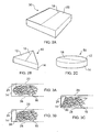
Figures 2A, 2B and 2C show perspective views of packs according to further embodiments, having various outer shapes; and -
Figures 3A, 3B and 3C show partial cross-sectional views of packs according to further embodiments, having various abutment members that limit movement of a lid portion. -
Figure 1A shows a perspective view of a pack according to an embodiment of the invention, the pack being in an open configuration.Figure 1B shows the same pack in a closed configuration. - The
pack 10 is in the form of a receptacle for tobacco, which in this embodiment has a parallelepiped shape. The receptacle is defined by anupper face 12, a lower face opposite the upper face 12 (not visible in the Figures), and fourside walls 14 that extend between and join the lower face and theupper face 12. In this example, theupper face 12 and the lower face each have a square shape. Also, the edges of theupper face 12 and the lower face are significantly longer than the vertical edges of theside walls 14, so that theupper face 12 and the lower face have a much greater surface area than theside walls 14. Hence the receptacle has the form of a shallow tray with a lid, where theupper face 12 forms the "lid" and acts to close the receptacle and retain its contents, in this caseloose tobacco 16. - The
upper face 12 is divided in two by ahinge line 18 that runs across theupper face 12 from one corner to the diagonally opposite corner. Thehinge line 18 is best seen inFigure 1B . Thehinge line 18 defines two portions: on one side of thehinge line 18 theupper face 12 has the form of alid portion 20, and on the other side of thehinge line 18 theupper face 12 has the form of afixed portion 22. Depending on the material and the manufacturing method used to make thepack 10, thehinge line 18 may be formed for example by a score line, a line of perforations, or a line of thinner material. - The
fixed portion 22 is joined at its edges other than the edge defined by thehinge line 18 to theside walls 14. Thefixed portion 22 thus has a fixed, closed position relative to the receptacle, and is not movable relative thereto. Tobacco 16 is accommodated in the space below the fixedportion 22, however. - The
lid portion 20 is not joined to the side walls, and is instead connected to the receptacle by way of thehinge line 18, so that it is continuous with thefixed portion 22. Thelid portion 20 is rotatable about thehinge line 18 between a closed position shown inFigure 1B and an open position shown inFigure 1A . When in the closed position, thelid portion 20 is in contact with or closely adjacent to the top edges of theside walls 14 so as to close the receptacle. Also, when in the closed position, thelid portion 20 and thefixed portion 22 are substantially co-planar, so that theupper face 12 has the form of a substantially flat surface. To open thepack 10, so as to gain access to the contents of the receptacle, the user lifts an edge of thelid portion 20 and rotates thelid portion 20 about thehinge line 18 so as to fold it towards thefixed portion 22. This opens an aperture under thelid portion 20 which is delineated by thehinge line 18 and the upper edges of theside walls 14. - This arrangement gives a pack that is particularly well-adapted to the needs of a smoker who wishes to roll his own cigarettes. The pack is easily opened (in some embodiments with one hand, as described later) to give access to the tobacco within. Once opened, the
fixed portion 22 of theupper face 12 offers a flat surface on which the smoker can deposittobacco 16 removed from thepack 10. This surface can also accommodate cigarette papers, matches, filters and the like while the smoker takes'tobacco 16 from thepack 10. Further, the flat surface can then be used as a surface on which to roll a cigarette using the tobacco from the pack, and more usefully, a larger area can be obtained by lowering thelid portion 20 back to its closed position, so that the whole of the upper surface forms a single flat plane on which the cigarette can be made. - The particular shape and configuration of pack shown in
Figures 1A and 1B is useful in that square packs can be more easily deposited into larger cartons for shipping, since it is immaterial which way round the pack is put into the carton. Also, the diagonal arrangement of the hinge line imparts rigidity to the pack, since the pack is then braced across its longest dimension. Improved rigidity reduces damage and crushing during shipping, storage and use of the pack. However, packs according to the invention are not limited to the configuration ofFigures 1A and 1B , and can take a wide range of shapes. - For example,
Figure 2A shows apack 30 which has the form of a square parallelepiped, like thepack 10 ofFigures 1A and 1B , but in which thehinge line 18 is positioned parallel to two opposite sides of theupper face 12. The two options of a diagonal hinge line or a parallel hinge line may similarly be implemented with a parallelepiped pack in which the upper and lower faces are rectangular. -
Figure 2B shows apack 40 in which theupper face 12 and the lower face are triangular, so that these faces are connected by threeside walls 14. Thehinge line 18 runs across theupper face 12 from one corner of the triangle to the centre of the opposite side. Other polygonal shapes can also be used, both regular and irregular. -
Figure 2C shows apack 50 in which theupper face 12 and the lower face are circular, connected by a singlecylindrical side wall 14. Thehinge line 18 is defined along a diameter of theupper face 12. The upper and lower faces may alternatively be oval. - Square, rounded or bevelled edges or corners may be used in conjunction with any shape of pack.
- In each of the above examples, the
hinge line 18 bisects theupper face 12, so that thelid portion 20 and fixedportion 22 have the same area. This maximises both the size of the aperture through which the user accesses the contents of thepack 10 and the available flat surface offered by the fixedportion 22 while thelid portion 20 is open. However, the hinge line may be positioned to divide the upper face into two unequal parts if desired. - Returning to
Figure 1A , it will be seen that thepack 10 further comprises a rim orabutment member 24. This is a portion that extends inwardly, towards the interior of the receptacle, from the upper edges of theside walls 14, at least on thoseside walls 14 adjacent to the edges of thelid portion 20. Therim 24 thus extends partly underneath thelid portion 20 so as to be adjacent to the underside edge of thelid portion 20 when thelid portion 20 is in its closed position. Thus, when thelid portion 20 is closed, it abuts therim 24. This arrangement stops thelid portion 20 from rotating too far about thehinge line 18, past its closed position, and falling down into the interior of the receptacle, from where it would be difficult to be opened. Also, the abutment with therim 24 keeps thelid portion 20 and the fixedportion 22 substantially coplanar if pressure is exerted on theupper face 22, thus maintaining theupper surface 12 flat while a cigarette is rolled upon it. -
Figure 3A shows a first example embodiment of therim 24, illustrated as a partial vertical cross-sectional view through a pack according to the invention. Therim 24 comprises a protruding flange extending from the upper edge of theside wall 14, at right angles thereto. The flange may be given rigidity so that it maintains its position under applied pressure by extending the flange continuously around corners of the pack, as inFigure 1A . This embodiment offers a relatively simple construction, and also uses a minimum of material. However,tobacco 16 that occupies the space under the rim may be difficult to remove from the pack, or may be overlooked altogether. -
Figure 3B shows a second example embodiment of therim 24, which addresses the above problem oftobacco 16 underneath therim 24 of the first example. In this embodiment, therim 24 comprises a flange like that of the first example, but which is supported by a downwardly extendingsupport member 26, which extends vertically between the inner edge of the flange and the upper surface of thelower face 28 of the receptacle. This give a strong structure similar to a box girder, giving rigidity to the pack and making it more resistant to crushing. Also, tobacco cannot become trapped or hidden in the space under the rim. However, the presence of thesupport member 26 reduces the interior volume of the receptacle and hence the amount of tobacco that can be provided in the pack. -
Figure 3C shows a third example embodiment of therim 24, which offers some of the increased strength of the second example, while increasing the available interior volume. In this example, the flange is supported by asloping support member 30 that extends between the inner edge of the flange and the outer edge of thelower face 28, to make a triangular box girder structure. - Note that for ease of understanding,
Figures 3A, 3B and 3C show thelid portion 20 spaced slightly apart from theabutment member 24, whereas in use, if the lid is securely closed and/or pressure is applied to theupper face 12, thelid portion 20 will likely contact theabutment member 24. - The abutment member may have other structures than those illustrated. For example, the rim may extend outwardly from the side walls rather than in wardly, if used in conjunction with an overhanging lid portion. Further, the abutment member need not be continuous along the side walls as in
Figure 1A . Instead, one or more individual abutment members may be positioned separately at various locations along the side walls. - Packs according to the invention further comprise a closure assembly by which the lid portion can be held in the closed position until the user desires to open the pack. A first example is illustrated in
Figures 1A and 1B . One edge of thelid portion 20 has a recessed, cut-outportion 32a extending along the greater part of its length from the end adjacent to thehinge line 18. The remaining part of the edge, adjacent to the corner opposite thehinge line 18 is not cut out and forms a protrudingportion 32b. The upper edge of the adjacent side wall is formed so as to have corresponding protruding and recessed portions. That is, the greater part of the edge is a protrudingportion 34a of the same length as the recessedportion 32a in the lid portion, and the remaining part of the edge, adjacent to the corner opposite thehinge line 18, is cut out to form a recessedportion 34b of the same length as the protrudingportion 32b. When thelid portion 20 is brought into its closed position, the protrudingportion 32b on the lid portion enters the recessedportion 34b on theside wall 14, and the protrudingportion 34a on theside wall 14 enters the recessedportion 32a on thelid portion 20. Because the corresponding portions have substantially equal lengths, this interengagement produces an interference fit, and thelid portion 20 is held closed. - The particular arrangement of protruding and recessed portions in
Figure 1A gives a small part of the lid portion (the protrudingportion 32b) located at the corner of the pack opposite thehinge line 18 that is accessible from theside wall 14. This portion can engaged using a finger or thumb, so that thelid portion 20 can be pushed upwards out of the interference fit closure and rotated about thehinge line 18 so as to open the pack. The pack can thereby conveniently be opened with one hand. However, other arrangements of engaging protruding and recessed portions can be used instead, although one-handed operation will be possible with at least some of the other possible configurations. - In the example of
Figure 1A , the distance by which the recessed portions are recessed from the protruding portions is equal to the thickness of the material from which the portions are made. This means that when the lid portion is closed and the portions are interengaged, there are no discontinuities (protrusions or depressions) in the plane of theupper face 20. A substantially smooth upper face is provided, with no parts in which loose bits of tobacco could become caught. Also, the appearance of the pack is enhanced by the smooth outer surface. The protruding and recessed portions may have other dimensions, however, although the example ofFigure 1 uses and wastes a minimum of material. - Packs according to the invention may further comprise a sealing layer (not shown) disposed under the
lid portion 20 to seal the aperture which is exposed when thelid portion 20 is opened. Such a sealing layer will keep thetobacco 16 in the pack fresh until the pack is first opened by a user. The sealing layer can be adhered to the edges of the aperture, for example adhered to therim 24 or to the upper edges of theside walls 14, in such a way that it can be peeled off and disposed of by the user on first opening the pack. Alternatively, the sealing layer may be resealable, so that it can be stuck back down over the aperture to maintain freshness of the tobacco after the pack has been opened. Additionally or alternatively, the pack may be provided with a removable outer wrapper, for example a cellophane or plastic wrapper, that is removed on first opening the pack. - The packs according to the invention can be fabricated from any suitable material and using any suitable technique. For example, the packs can be assembled by folding and gluing one or more blanks of cardboard or stiff paper in the manner used to make conventional crush-proof cigarette packs. Alternatively, the packs can be made from plastics materials, for example by moulding, including injection moulding or thermoforming. The shape of the pack may determine the choice of material and fabrication technique. For example, the circular pack of
Figure 2C may be simpler to make from plastics than from cardboard. The interengaging closure portions inFigure 1A may also be found to be more conveniently implemented for a plastics pack. - The packs are not limited to being packs for tobacco intended for the hand- rolling of cigarettes. Although many features of the packs are of particular use for cigarette rolling, other features such as the outer shape and rigidity being advantageous for packing, shipping, storing and vending are relevant for other tobacco products. For example, the tobacco may be pipe tobacco, loose snus or portion snus.
Claims (5)
- A pack for tobacco comprising a receptacle for receiving tobacco, the receptacle having an upper face (12) that closes the receptacle, and a hinge line (18) running across the upper face (12), the hinge line (18) dividing the upper face (12) into a lid portion (20) and a fixed portion (22), the fixed portion (22) remaining in a closed position and the lid portion (20) rotatable about the hinge line (18) between a closed position that is substantially coplanar with the fixed portion (22), and an open position that gives access to the interior of the receptacle, wherein the receptacle has one or more side walls (14), characterised in that the pack further comprises one or more abutment members (24) extending from upper edges of said side wall(s) so as to be adjacent to the underside of the lid portion (20), when said lid portion (20) is in a closed position, to inhibit the lid portion (20) from rotating below the plane of the fixed portion (22), the pack further comprises a closure assembly operable to releasably maintain the lid in its closed position, the closure assembly comprising one or more recessed portions (32a) on an edge of the lid portion (20), and one or more corresponding protruding portions (34a) upstanding on an adjacent edge of the receptacle, the portions on the edge of the lid portion (20) inter-engaging with the portions on the adjacent edge in an interference fit when the lid portion (20) is in a closed position
- A pack according to claim 1, in which the receptacle has a parallel piped shape, defined by the upper face (12), a lower face opposite the upper face, and four side walls (14) extending between the upper face (12) and the lower face, the upper and lower faces having a substantially larger area than the side walls (14).
- A pack according to claim 2, in which the hinge line (18) runs between two opposite corners of the upper face (12).
- A pack according to any preceding claim, in which the closure assembly is configured such that when the lid is in the closed position there are substantially no discontinuities in the plane of the upper surface.
- A pack according to any preceding claim, in which the pack is formed from a folded blank.
Priority Applications (1)
| Application Number | Priority Date | Filing Date | Title |
|---|---|---|---|
| PL07823986T PL2091826T3 (en) | 2006-10-03 | 2007-10-02 | Pack for tobacco |
Applications Claiming Priority (2)
| Application Number | Priority Date | Filing Date | Title |
|---|---|---|---|
| GBGB0619532.5A GB0619532D0 (en) | 2006-10-03 | 2006-10-03 | Pack for tobacco |
| PCT/GB2007/003729 WO2008040955A1 (en) | 2006-10-03 | 2007-10-02 | Pack for tobacco |
Publications (2)
| Publication Number | Publication Date |
|---|---|
| EP2091826A1 EP2091826A1 (en) | 2009-08-26 |
| EP2091826B1 true EP2091826B1 (en) | 2011-04-27 |
Family
ID=37453898
Family Applications (1)
| Application Number | Title | Priority Date | Filing Date |
|---|---|---|---|
| EP07823986A Not-in-force EP2091826B1 (en) | 2006-10-03 | 2007-10-02 | Pack for tobacco |
Country Status (11)
| Country | Link |
|---|---|
| EP (1) | EP2091826B1 (en) |
| AR (1) | AR063951A1 (en) |
| AT (1) | ATE507153T1 (en) |
| AU (1) | AU2007304042B2 (en) |
| CA (1) | CA2665077A1 (en) |
| DE (1) | DE602007014254D1 (en) |
| ES (1) | ES2365559T3 (en) |
| GB (1) | GB0619532D0 (en) |
| NZ (1) | NZ575798A (en) |
| PL (1) | PL2091826T3 (en) |
| WO (1) | WO2008040955A1 (en) |
Families Citing this family (1)
| Publication number | Priority date | Publication date | Assignee | Title |
|---|---|---|---|---|
| GB201201206D0 (en) * | 2012-01-25 | 2012-03-07 | British American Tobacco Co | A pack for smoking articles |
Family Cites Families (5)
| Publication number | Priority date | Publication date | Assignee | Title |
|---|---|---|---|---|
| DE2804211A1 (en) * | 1978-02-01 | 1979-08-02 | Vinciguerra Antonio | One-piece blank pizza packaging - made of cardboard and including protruding closure flap facilitating opening and closing |
| FR2620428B1 (en) * | 1987-09-11 | 1990-03-02 | Fuller France H B | CARDBOARD BOX WITH POURING DEVICE |
| BR0116563A (en) * | 2000-12-27 | 2004-02-17 | Siegfried Galter | Container |
| DE10332774A1 (en) * | 2003-05-02 | 2004-12-02 | Miskowic, Darko | Pack for filter cigarettes has swiveling top, through which cigarettes can be removed by grasping filter, smaller, swiveling corner at base allowing them to be removed by gripping opposite end |
| ITBO20040520A1 (en) * | 2004-08-09 | 2004-11-09 | Gd Spa | RIGID WRAPPING FOR SMOKING ITEMS WITH HINGED COVER PRESENTING AN OPENING SOUND |
-
2006
- 2006-10-03 GB GBGB0619532.5A patent/GB0619532D0/en not_active Ceased
-
2007
- 2007-10-02 AT AT07823986T patent/ATE507153T1/en not_active IP Right Cessation
- 2007-10-02 DE DE602007014254T patent/DE602007014254D1/en active Active
- 2007-10-02 ES ES07823986T patent/ES2365559T3/en active Active
- 2007-10-02 EP EP07823986A patent/EP2091826B1/en not_active Not-in-force
- 2007-10-02 CA CA002665077A patent/CA2665077A1/en not_active Abandoned
- 2007-10-02 PL PL07823986T patent/PL2091826T3/en unknown
- 2007-10-02 WO PCT/GB2007/003729 patent/WO2008040955A1/en active Application Filing
- 2007-10-02 NZ NZ575798A patent/NZ575798A/en not_active IP Right Cessation
- 2007-10-02 AU AU2007304042A patent/AU2007304042B2/en not_active Ceased
- 2007-10-03 AR ARP070104385A patent/AR063951A1/en not_active Application Discontinuation
Also Published As
| Publication number | Publication date |
|---|---|
| CA2665077A1 (en) | 2008-04-10 |
| DE602007014254D1 (en) | 2011-06-09 |
| GB0619532D0 (en) | 2006-11-15 |
| AR063951A1 (en) | 2009-03-04 |
| PL2091826T3 (en) | 2011-09-30 |
| ATE507153T1 (en) | 2011-05-15 |
| AU2007304042B2 (en) | 2011-09-01 |
| AU2007304042A1 (en) | 2008-04-10 |
| ES2365559T3 (en) | 2011-10-06 |
| NZ575798A (en) | 2011-06-30 |
| WO2008040955A1 (en) | 2008-04-10 |
| EP2091826A1 (en) | 2009-08-26 |
Similar Documents
| Publication | Publication Date | Title |
|---|---|---|
| US7617930B2 (en) | Cigarette package | |
| KR101299329B1 (en) | Box containing loose smokable material | |
| US4588081A (en) | Folding carton and blank therefor, for cigarettes | |
| KR102632751B1 (en) | Container with improved closure mechanism | |
| US20080093233A1 (en) | Cigarette package | |
| US20140124395A1 (en) | Container and lifting means for an article | |
| US20150041346A1 (en) | Resealable container having tactile elements | |
| JP2004528051A (en) | Box with lid | |
| JP6948318B2 (en) | Resealable container containing inserts | |
| KR20210118433A (en) | Rigid packs for smoking articles with double hinged lids and blanks for making rigid packs for smoking articles | |
| TW201331099A (en) | Container with integrally connected receptacles | |
| US8813956B2 (en) | Container with side opening | |
| EP2091826B1 (en) | Pack for tobacco | |
| CA2084622A1 (en) | Rounded end cigarette box | |
| US10421602B2 (en) | Container for consumer goods with sliding portion | |
| EP3240739B1 (en) | Container for consumer goods having opening and closing mechanism | |
| EP2094573B1 (en) | Pack for tobacco | |
| EP2403765A1 (en) | Hinge lid container | |
| GB2447958A (en) | Tobacco container with overlapping seals | |
| WO2018002844A1 (en) | Container for consumer goods including dispensing device |
Legal Events
| Date | Code | Title | Description |
|---|---|---|---|
| PUAI | Public reference made under article 153(3) epc to a published international application that has entered the european phase |
Free format text: ORIGINAL CODE: 0009012 |
|
| 17P | Request for examination filed |
Effective date: 20090430 |
|
| AK | Designated contracting states |
Kind code of ref document: A1 Designated state(s): AT BE BG CH CY CZ DE DK EE ES FI FR GB GR HU IE IS IT LI LT LU LV MC MT NL PL PT RO SE SI SK TR |
|
| 17Q | First examination report despatched |
Effective date: 20090921 |
|
| DAX | Request for extension of the european patent (deleted) | ||
| GRAP | Despatch of communication of intention to grant a patent |
Free format text: ORIGINAL CODE: EPIDOSNIGR1 |
|
| GRAS | Grant fee paid |
Free format text: ORIGINAL CODE: EPIDOSNIGR3 |
|
| GRAA | (expected) grant |
Free format text: ORIGINAL CODE: 0009210 |
|
| AK | Designated contracting states |
Kind code of ref document: B1 Designated state(s): AT BE BG CH CY CZ DE DK EE ES FI FR GB GR HU IE IS IT LI LT LU LV MC MT NL PL PT RO SE SI SK TR |
|
| REG | Reference to a national code |
Ref country code: GB Ref legal event code: FG4D |
|
| REG | Reference to a national code |
Ref country code: CH Ref legal event code: EP |
|
| REG | Reference to a national code |
Ref country code: IE Ref legal event code: FG4D |
|
| REF | Corresponds to: |
Ref document number: 602007014254 Country of ref document: DE Date of ref document: 20110609 Kind code of ref document: P |
|
| REG | Reference to a national code |
Ref country code: DE Ref legal event code: R096 Ref document number: 602007014254 Country of ref document: DE Effective date: 20110609 |
|
| REG | Reference to a national code |
Ref country code: CH Ref legal event code: NV Representative=s name: KIRKER & CIE S.A. |
|
| REG | Reference to a national code |
Ref country code: NL Ref legal event code: T3 |
|
| LTIE | Lt: invalidation of european patent or patent extension |
Effective date: 20110427 |
|
| REG | Reference to a national code |
Ref country code: PL Ref legal event code: T3 |
|
| REG | Reference to a national code |
Ref country code: ES Ref legal event code: FG2A Ref document number: 2365559 Country of ref document: ES Kind code of ref document: T3 Effective date: 20111006 |
|
| PG25 | Lapsed in a contracting state [announced via postgrant information from national office to epo] |
Ref country code: LT Free format text: LAPSE BECAUSE OF FAILURE TO SUBMIT A TRANSLATION OF THE DESCRIPTION OR TO PAY THE FEE WITHIN THE PRESCRIBED TIME-LIMIT Effective date: 20110427 Ref country code: SE Free format text: LAPSE BECAUSE OF FAILURE TO SUBMIT A TRANSLATION OF THE DESCRIPTION OR TO PAY THE FEE WITHIN THE PRESCRIBED TIME-LIMIT Effective date: 20110427 Ref country code: PT Free format text: LAPSE BECAUSE OF FAILURE TO SUBMIT A TRANSLATION OF THE DESCRIPTION OR TO PAY THE FEE WITHIN THE PRESCRIBED TIME-LIMIT Effective date: 20110829 |
|
| PG25 | Lapsed in a contracting state [announced via postgrant information from national office to epo] |
Ref country code: AT Free format text: LAPSE BECAUSE OF FAILURE TO SUBMIT A TRANSLATION OF THE DESCRIPTION OR TO PAY THE FEE WITHIN THE PRESCRIBED TIME-LIMIT Effective date: 20110427 Ref country code: IS Free format text: LAPSE BECAUSE OF FAILURE TO SUBMIT A TRANSLATION OF THE DESCRIPTION OR TO PAY THE FEE WITHIN THE PRESCRIBED TIME-LIMIT Effective date: 20110827 Ref country code: FI Free format text: LAPSE BECAUSE OF FAILURE TO SUBMIT A TRANSLATION OF THE DESCRIPTION OR TO PAY THE FEE WITHIN THE PRESCRIBED TIME-LIMIT Effective date: 20110427 Ref country code: CY Free format text: LAPSE BECAUSE OF FAILURE TO SUBMIT A TRANSLATION OF THE DESCRIPTION OR TO PAY THE FEE WITHIN THE PRESCRIBED TIME-LIMIT Effective date: 20110427 Ref country code: GR Free format text: LAPSE BECAUSE OF FAILURE TO SUBMIT A TRANSLATION OF THE DESCRIPTION OR TO PAY THE FEE WITHIN THE PRESCRIBED TIME-LIMIT Effective date: 20110728 Ref country code: SI Free format text: LAPSE BECAUSE OF FAILURE TO SUBMIT A TRANSLATION OF THE DESCRIPTION OR TO PAY THE FEE WITHIN THE PRESCRIBED TIME-LIMIT Effective date: 20110427 Ref country code: LV Free format text: LAPSE BECAUSE OF FAILURE TO SUBMIT A TRANSLATION OF THE DESCRIPTION OR TO PAY THE FEE WITHIN THE PRESCRIBED TIME-LIMIT Effective date: 20110427 |
|
| REG | Reference to a national code |
Ref country code: HU Ref legal event code: AG4A Ref document number: E011749 Country of ref document: HU |
|
| PG25 | Lapsed in a contracting state [announced via postgrant information from national office to epo] |
Ref country code: CZ Free format text: LAPSE BECAUSE OF FAILURE TO SUBMIT A TRANSLATION OF THE DESCRIPTION OR TO PAY THE FEE WITHIN THE PRESCRIBED TIME-LIMIT Effective date: 20110427 Ref country code: EE Free format text: LAPSE BECAUSE OF FAILURE TO SUBMIT A TRANSLATION OF THE DESCRIPTION OR TO PAY THE FEE WITHIN THE PRESCRIBED TIME-LIMIT Effective date: 20110427 |
|
| PG25 | Lapsed in a contracting state [announced via postgrant information from national office to epo] |
Ref country code: DK Free format text: LAPSE BECAUSE OF FAILURE TO SUBMIT A TRANSLATION OF THE DESCRIPTION OR TO PAY THE FEE WITHIN THE PRESCRIBED TIME-LIMIT Effective date: 20110427 Ref country code: RO Free format text: LAPSE BECAUSE OF FAILURE TO SUBMIT A TRANSLATION OF THE DESCRIPTION OR TO PAY THE FEE WITHIN THE PRESCRIBED TIME-LIMIT Effective date: 20110427 Ref country code: SK Free format text: LAPSE BECAUSE OF FAILURE TO SUBMIT A TRANSLATION OF THE DESCRIPTION OR TO PAY THE FEE WITHIN THE PRESCRIBED TIME-LIMIT Effective date: 20110427 |
|
| PLBE | No opposition filed within time limit |
Free format text: ORIGINAL CODE: 0009261 |
|
| STAA | Information on the status of an ep patent application or granted ep patent |
Free format text: STATUS: NO OPPOSITION FILED WITHIN TIME LIMIT |
|
| 26N | No opposition filed |
Effective date: 20120130 |
|
| REG | Reference to a national code |
Ref country code: DE Ref legal event code: R097 Ref document number: 602007014254 Country of ref document: DE Effective date: 20120130 |
|
| PG25 | Lapsed in a contracting state [announced via postgrant information from national office to epo] |
Ref country code: MC Free format text: LAPSE BECAUSE OF NON-PAYMENT OF DUE FEES Effective date: 20111031 |
|
| REG | Reference to a national code |
Ref country code: IE Ref legal event code: MM4A |
|
| PG25 | Lapsed in a contracting state [announced via postgrant information from national office to epo] |
Ref country code: IE Free format text: LAPSE BECAUSE OF NON-PAYMENT OF DUE FEES Effective date: 20111002 |
|
| PG25 | Lapsed in a contracting state [announced via postgrant information from national office to epo] |
Ref country code: MT Free format text: LAPSE BECAUSE OF FAILURE TO SUBMIT A TRANSLATION OF THE DESCRIPTION OR TO PAY THE FEE WITHIN THE PRESCRIBED TIME-LIMIT Effective date: 20110427 |
|
| PG25 | Lapsed in a contracting state [announced via postgrant information from national office to epo] |
Ref country code: LU Free format text: LAPSE BECAUSE OF NON-PAYMENT OF DUE FEES Effective date: 20111002 |
|
| PG25 | Lapsed in a contracting state [announced via postgrant information from national office to epo] |
Ref country code: BG Free format text: LAPSE BECAUSE OF FAILURE TO SUBMIT A TRANSLATION OF THE DESCRIPTION OR TO PAY THE FEE WITHIN THE PRESCRIBED TIME-LIMIT Effective date: 20110727 |
|
| PG25 | Lapsed in a contracting state [announced via postgrant information from national office to epo] |
Ref country code: TR Free format text: LAPSE BECAUSE OF FAILURE TO SUBMIT A TRANSLATION OF THE DESCRIPTION OR TO PAY THE FEE WITHIN THE PRESCRIBED TIME-LIMIT Effective date: 20110427 |
|
| PGFP | Annual fee paid to national office [announced via postgrant information from national office to epo] |
Ref country code: PL Payment date: 20130923 Year of fee payment: 7 |
|
| PGFP | Annual fee paid to national office [announced via postgrant information from national office to epo] |
Ref country code: BE Payment date: 20131022 Year of fee payment: 7 Ref country code: CH Payment date: 20131021 Year of fee payment: 7 Ref country code: FR Payment date: 20131022 Year of fee payment: 7 Ref country code: DE Payment date: 20131021 Year of fee payment: 7 Ref country code: GB Payment date: 20131021 Year of fee payment: 7 |
|
| PGFP | Annual fee paid to national office [announced via postgrant information from national office to epo] |
Ref country code: IT Payment date: 20131028 Year of fee payment: 7 Ref country code: NL Payment date: 20131022 Year of fee payment: 7 Ref country code: ES Payment date: 20131017 Year of fee payment: 7 Ref country code: HU Payment date: 20131021 Year of fee payment: 7 |
|
| REG | Reference to a national code |
Ref country code: DE Ref legal event code: R119 Ref document number: 602007014254 Country of ref document: DE |
|
| REG | Reference to a national code |
Ref country code: NL Ref legal event code: V1 Effective date: 20150501 |
|
| REG | Reference to a national code |
Ref country code: CH Ref legal event code: PL |
|
| GBPC | Gb: european patent ceased through non-payment of renewal fee |
Effective date: 20141002 |
|
| PG25 | Lapsed in a contracting state [announced via postgrant information from national office to epo] |
Ref country code: BE Free format text: LAPSE BECAUSE OF NON-PAYMENT OF DUE FEES Effective date: 20141031 |
|
| PG25 | Lapsed in a contracting state [announced via postgrant information from national office to epo] |
Ref country code: LI Free format text: LAPSE BECAUSE OF NON-PAYMENT OF DUE FEES Effective date: 20141031 Ref country code: CH Free format text: LAPSE BECAUSE OF NON-PAYMENT OF DUE FEES Effective date: 20141031 Ref country code: DE Free format text: LAPSE BECAUSE OF NON-PAYMENT OF DUE FEES Effective date: 20150501 Ref country code: GB Free format text: LAPSE BECAUSE OF NON-PAYMENT OF DUE FEES Effective date: 20141002 |
|
| REG | Reference to a national code |
Ref country code: FR Ref legal event code: ST Effective date: 20150630 |
|
| PG25 | Lapsed in a contracting state [announced via postgrant information from national office to epo] |
Ref country code: NL Free format text: LAPSE BECAUSE OF NON-PAYMENT OF DUE FEES Effective date: 20150501 Ref country code: HU Free format text: LAPSE BECAUSE OF NON-PAYMENT OF DUE FEES Effective date: 20141003 Ref country code: FR Free format text: LAPSE BECAUSE OF NON-PAYMENT OF DUE FEES Effective date: 20141031 Ref country code: IT Free format text: LAPSE BECAUSE OF NON-PAYMENT OF DUE FEES Effective date: 20141002 |
|
| REG | Reference to a national code |
Ref country code: ES Ref legal event code: FD2A Effective date: 20151126 |
|
| PG25 | Lapsed in a contracting state [announced via postgrant information from national office to epo] |
Ref country code: PL Free format text: LAPSE BECAUSE OF NON-PAYMENT OF DUE FEES Effective date: 20141002 Ref country code: ES Free format text: LAPSE BECAUSE OF NON-PAYMENT OF DUE FEES Effective date: 20141003 |