EP2091817B1 - Verfahren und vorrichtung zum aufblasen einer aufblasbaren struktur - Google Patents
Verfahren und vorrichtung zum aufblasen einer aufblasbaren struktur Download PDFInfo
- Publication number
- EP2091817B1 EP2091817B1 EP07858547A EP07858547A EP2091817B1 EP 2091817 B1 EP2091817 B1 EP 2091817B1 EP 07858547 A EP07858547 A EP 07858547A EP 07858547 A EP07858547 A EP 07858547A EP 2091817 B1 EP2091817 B1 EP 2091817B1
- Authority
- EP
- European Patent Office
- Prior art keywords
- inflatable structure
- flow rate
- storage tank
- filling gas
- pressure
- Prior art date
- Legal status (The legal status is an assumption and is not a legal conclusion. Google has not performed a legal analysis and makes no representation as to the accuracy of the status listed.)
- Not-in-force
Links
Images


Classifications
-
- B—PERFORMING OPERATIONS; TRANSPORTING
- B64—AIRCRAFT; AVIATION; COSMONAUTICS
- B64G—COSMONAUTICS; VEHICLES OR EQUIPMENT THEREFOR
- B64G1/00—Cosmonautic vehicles
- B64G1/22—Parts of, or equipment specially adapted for fitting in or to, cosmonautic vehicles
- B64G1/222—Parts of, or equipment specially adapted for fitting in or to, cosmonautic vehicles for deploying structures between a stowed and deployed state
- B64G1/2221—Parts of, or equipment specially adapted for fitting in or to, cosmonautic vehicles for deploying structures between a stowed and deployed state characterised by the manner of deployment
- B64G1/2227—Inflating
-
- B—PERFORMING OPERATIONS; TRANSPORTING
- B64—AIRCRAFT; AVIATION; COSMONAUTICS
- B64G—COSMONAUTICS; VEHICLES OR EQUIPMENT THEREFOR
- B64G1/00—Cosmonautic vehicles
- B64G1/22—Parts of, or equipment specially adapted for fitting in or to, cosmonautic vehicles
- B64G1/52—Protection, safety or emergency devices; Survival aids
- B64G1/58—Thermal protection, e.g. heat shields
-
- B—PERFORMING OPERATIONS; TRANSPORTING
- B64—AIRCRAFT; AVIATION; COSMONAUTICS
- B64G—COSMONAUTICS; VEHICLES OR EQUIPMENT THEREFOR
- B64G1/00—Cosmonautic vehicles
- B64G1/22—Parts of, or equipment specially adapted for fitting in or to, cosmonautic vehicles
- B64G1/66—Arrangements or adaptations of apparatus or instruments, not otherwise provided for
Definitions
- the present invention relates to a method and a device for inflating an inflatable structure.
- the invention particularly relates to a method and a device for inflating an inflatable structure of the "Gossamer” type for satellite or space vehicle (launcher), cf. XP 000 623 252.
- These structures are sometimes inflated with gas stored in a tank under pressure (under pressure to reduce the mass of the tank).
- the present invention is applicable to any type of gas (nitrogen, helium, argon for example), whether neutral or not.
- the deployment phase of the inflatable structure takes place at low pressure (a few tens of mbar typically in the structure) and must be performed at low flow to avoid the risk of blockage or tearing of the inflatable structure.
- the pressurization phase is terminated when the pressure in the inflatable structure reaches a value such that the structure has undergone permanent plastic deformation (or polymerization).
- the inflatable structure may be made of polymer (for example "Kapton” or "Mylar"), material having a natural leakage rate due to its porosity (and / or assembly of the various panels constituting the inflatable structure).
- the figure 1 illustrates a known inflation system consisting of a high pressure tank 2 in which is stored the pressurized gas, at a typical pressure of 200 to 400 bar.
- This tank is generally in composite or metallic structure. This is the heaviest element of the system. Its volume must therefore be as small as possible for use on a satellite or a launcher.
- the system also includes a pipe with a filling valve 10 generally with manual opening and closing, which makes it possible to fill the tank 2.
- the tank 2 is connected to the inflatable structure 1 by a pipe 3 comprising in series, from upstream to downstream, a valve 11, for example mono-stable ( possibly bi-stable) for connecting the tank 2 under pressure and the structure 1 to be deployed and a calibrated orifice 4 for controlling the filling flow D to limit the speed of deployment of the structure 1.
- a valve 11 for example mono-stable ( possibly bi-stable) for connecting the tank 2 under pressure and the structure 1 to be deployed and a calibrated orifice 4 for controlling the filling flow D to limit the speed of deployment of the structure 1.
- the inflation device may be equipped with a system for limiting the pressure, such as a valve, a rupture disc or a valve (not shown).
- a system for limiting the pressure such as a valve, a rupture disc or a valve (not shown).
- the inflatable structure 1 may have a natural leakage rate F (because of its porosity).
- the inflatable structure 1 generally has a limited deployment speed. Insofar as the deployment is done at low pressure (typically a few tens of mbar), the leakage rate F leaving the structure 1 is then negligible compared to the inflation rate entering the structure 1. At the deployment speed of structure 1 corresponds to an initial gas mass flow rate. This initial mass flow rate and the pressure of the tank 2 (as well as the characteristics of the gas) determine the size of the orifice 4.
- This orifice 4 may have a flow / pressure characteristic of a sonic orifice if the diameter is sufficiently large (several tens of microns to allow a laser drilling or with a drill) or a capillary orifice if the orifice is made of sintered metal or of a capillary tube.
- the volume of the structure remains constant and the pressure in the inflatable structure increases.
- the pressure in the structure must reach a certain limit, typically around 1 bar, so that the plastic deformation of the structure then allows it to maintain its shape without continual addition of gas (to compensate for natural leakage in particular).
- An object of the present invention is to overcome all or part of the disadvantages of the prior art noted above.
- Another object of the invention is to provide an inflation device overcoming all or part of the disadvantages of the prior art noted above.
- the device according to the invention comprises an inflatable structure which is defined by claim 8, the switching element being of passive type and sensitive to the pressure in the storage tank.
- the filling gas flow control utilizes a counterbalance 6 and a calibrated orifice 5 installed in parallel.
- the discharger 6 is a member which, unlike a valve, closes when the pressure upstream is greater than a predetermined threshold (corresponding for example to the setting of a spring).
- the discharger 6 opens and becomes passing at a determined flow rate when the upstream pressure is below this threshold (or as a function of a pressure differential between the upstream and downstream ends of the discharge).
- the discharge 6 When the gas in the tank 2 is at a relatively high pressure, the discharge 6 is closed, and the orifice 5 is sized to pass a gas flow to deploy the structure 1 at the desired speed.
- the flow rate and therefore the speed of deployment are substantially constant since this phase consumes little gas (the pressure of the storage tank 2 evolves very little, typically the order of 1 to 3%).
- the pressure P in the tank reaches a determined lower value, typically 80 to 90% of the initial pressure Po, the discharger 6 opens and also allows the passage of filling gas to pressurize the inflatable structure 1 quickly ( preferably with a flow much higher than the leakage rate F by porosity of the structure 1).
- flow control is provided by a system comprising a plenum 8 and two orifices 7, 9 calibrated.
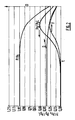
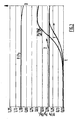
- the pressure of the plenum 8 is low (for example, space vacuum) and the flow rate D9 of gas via the second orifice 9 is much smaller than the flow rate D7 of gas via the first orifice 7. In this way, the inflatable structure is deployed at a slow speed (cf. figure 6 ).
- the plenum 8 fills and the pressure in the plenum 8 increases. There is thus a phase during which the mass flow through the first orifice 7 decreases as the pressure of the reservoir 2 and the flow via the second orifice 9 increases as the pressure of the plenum squared.
- the inflation rate of the structure 2 (flow via the second orifice 9) thus increases significantly, which makes it possible to have a pressurization and an inflation rate greater than the leakage rate of the structure, if appropriate (cf. figure 6 where is also represented the flow D9 via the second orifice 9.
- the invention has many advantages.
- reducing the volume of the plenum 8 increases the maximum pressure reached in the plenum 8.
- the volume of the plenum 8 can be optimized so that the ratio of the pressure in the tank 2 to the pressure in the plenum 8 remains greater than two (sonic flow) as long as the limit pressure in the inflatable structure 2 has not been reached.
- the first orifice 7 is preferably of the sonic type.
- the flow entering the plenum 8 decreases as the pressure P of the tank 2.
- the second orifice 9 is preferably of the capillary type.
- the outflow rate of the plenum 8 changes as the pressure of the plenum 8 squared and thus increases significantly between the deployment phase of the structure 1 (for which the pressure of the plenum 8 is still relatively weak) and the pressurization phase of the structure 1 (for which the pressure of the plenum 8 becomes relatively large).
- the invention makes it possible to improve the inflatable structure filling by means of a passive system.
Landscapes
- Engineering & Computer Science (AREA)
- Remote Sensing (AREA)
- Aviation & Aerospace Engineering (AREA)
- Filling Or Discharging Of Gas Storage Vessels (AREA)
- Air Bags (AREA)
- Blow-Moulding Or Thermoforming Of Plastics Or The Like (AREA)
- Pharmaceuticals Containing Other Organic And Inorganic Compounds (AREA)
- Shaping By String And By Release Of Stress In Plastics And The Like (AREA)
Claims (11)
- Verfahren zum Aufblasen einer aufblasbaren Struktur des "Gossamer"-Typs, das zwei Phasen enthält: eine Phase des Entfaltens der aufblasbaren Struktur mittels eines Füllgases, das von einem Vorratsbehälter (2) für mit Druck beaufschlagtes Gas geliefert wird, und eine Druckbeaufschlagungsphase, um die aufblasbare Struktur (1) mittels des von dem Vorratsbehälter (2) gelieferten Füllgases dauerhaft zu verformen, wobei das Verfahren einen Schritt des Steuerns des Füllgas-Durchflusses (D) enthält, um eine Beschädigung der aufblasbaren Struktur (1) insbesondere bei ihrer Entfaltung wenigstens während eines Teils der Druckbeaufschlagungsphase zu verhindern, wobei der Füllgas-Durchfluss (D) auf einem Wert oberhalb des Füllgas-Durchflusses während der Entfaltungsphase gehalten wird und wobei die Phasen des Entfaltens und der Druckbeaufschlagung der aufblasbaren Struktur (1) durch Druckausgleich zwischen dem Vorratsbehälter (2) für mit Druck beaufschlagtes Gas und der aufblasbaren Struktur (1) ausgeführt werden, dadurch gekennzeichnet, dass der Übergang zwischen den Phasen des Entfaltens und der Druckbeaufschlagung durch passive Umschaltmittel ausgeführt wird.
- Verfahren nach Anspruch 1, dadurch gekennzeichnet, dass der Übergang zwischen den Phasen des Entfaltens und der Druckbeaufschlagung als Echtzeit-Funktion des Drucks im Vorratsbehälter (2) ausgeführt wird.
- Verfahren nach einem der Ansprüche 1 oder 2, dadurch gekennzeichnet, dass der Übergang zwischen den Phasen des Entfaltens und der Druckbeaufschlagung automatisch als Funktion der Druckdifferenz zwischen der Eingangsseite und der Ausgangsseite eines Umschaltorgans, das in einer den Vorratsbehälter (2) mit der aufblasbaren Struktur verbindenden Leitung angeordnet ist, ausgeführt wird.
- Verfahren nach einem der Ansprüche 1 bis 3, dadurch gekennzeichnet, dass der Schritt des Steuerns des Füllgas-Durchflusses (D) automatisch auf passivem Weg als Funktion der Eigenschaften des momentanen Drucks in dem Vorratsbehälter (2) ausgeführt wird.
- Verfahren nach einem der vorhergehenden Ansprüche, dadurch gekennzeichnet, dass wenigstens während eines Teils des Übergangs des Füllgases von dem Vorratsbehälter (2) in die aufblasbare Struktur (1) der Füllgas-Durchfluss (D) so gesteuert wird, dass er umgekehrt proportional zum momentanen Druck (P) im Vorratsbehälter (2) geändert wird.
- Verfahren nach einem der vorhergehenden Ansprüche, dadurch gekennzeichnet, dass wenigstens während eines Teils des Übergangs des Füllgases von dem Vorratsbehälter (2) in die aufblasbare Struktur (1) der Füllgas-Durchfluss (D) so gesteuert wird, dass er sich gemäß einem Gesetz des Typs D = c1 · Pn verändert, wobei n eine Zahl kleiner als null ist, c1 eine Konstante ist und P der Wert des momentanen Drucks in dem Vorratsbehälter (2) ist.
- Verfahren nach einem der vorhergehenden Ansprüche, dadurch gekennzeichnet, dass wenigstens während eines Teils der Druckbeaufschlagungsphase der Füllgas-Durchfluss (D) auf einen Wert oberhalb des Leckdurchflusses (F) des Gases, das aus der aufblasbaren Struktur (1) aufgrund seiner Porosität entweicht, festgelegt wird.
- Vorrichtung zum Aufblasen einer aufblasbaren Struktur (1) des "Gossamer"-Typs, mit einem Vorratsbehälter (2) für mit Druck beaufschlagtes Gas, einem Kreis (3), der den Übergang des Gases durch Druckausgleich von dem Vorratsbehälter (2) in die aufblasbare Struktur (1) bewerkstelligen kann, und einem System (5, 6; 7 bis 9) für die Steuerung des Durchflusses (D) des Füllgases, das sich in den Kreis (3) bewegt, wobei das System (5, 6; 7 bis 9) für die Steuerung des Durchflusses (D) wenigstens zwei Organe (5, 6; 7, 9) für die Begrenzung des Durchflusses auf jeweils unterschiedliche Werte sowie ein Umschaltelement, um das System (5, 6; 7 bis 9) für die Steuerung des Durchflusses zwischen wenigstens zwei Zuständen umzuschalten, in denen das Füllgas verschiedene Organe (5, 6; 7, 9) für die Begrenzung des Durchflusses oder verschiedene Kombinationen dieser Organe (5, 6; 7, 9) für die Begrenzung des Durchflusses passiert, enthält, dadurch gekennzeichnet, dass das Umschaltelement vom passiven Typ ist und auf den Druck im Vorratsbehälter (2) anspricht.
- Vorrichtung nach Anspruch 8, dadurch gekennzeichnet, dass das System (5, 6; 7 bis 9) für die Steuerung des Durchflusses (D) in einer Leitung des Kreises (3) zwischen dem Vorratsbehälter (2) für mit Druck beaufschlagtes Gas und der aufblasbaren Struktur (1) in einer Serienschaltung eine erste kalibrierte Blende (7), einen Pufferbehälter oder ein Plenum (8) und eine zweite kalibrierte Blende (9) enthält, wobei der Durchfluss durch die erste kalibrierte Blende (7) größer ist als der Durchfluss durch die zweite kalibrierte Blende (9).
- Vorrichtung nach Anspruch 8, dadurch gekennzeichnet, dass die erste kalibrierte Blende (7) vom akustischen Typ ist und die zweite kalibrierte Blende (9) vom kapillaren Typ ist.
- Vorrichtung nach Anspruch 8 oder 9, dadurch gekennzeichnet, dass das System (5, 6; 7 bis 9) für die Steuerung des Durchflusses (D) in einer Leitung des Kreises (3) in einer Parallelschaltung eine kalibrierte Blende (5) und ein Einlauforgan (6) enthält, wobei das Einlauforgan (6) dazu ausgebildet ist, das Gas mit einem unterschiedlichen Durchfluss, der vorzugsweise höher als der Durchfluss der kalibrierten Blende (5) ist, und ausschließlich dann, wenn der auf der Einlassseite des Einlaufs (6) herrschende Druck kleiner als ein bestimmter Wert ist, durchzulassen.
Applications Claiming Priority (2)
| Application Number | Priority Date | Filing Date | Title |
|---|---|---|---|
| FR0654904A FR2908386B1 (fr) | 2006-11-15 | 2006-11-15 | Procede et dispositif de gonflage d'une structure gonflable. |
| PCT/FR2007/052117 WO2008059146A2 (fr) | 2006-11-15 | 2007-10-10 | Procédé et dispositif de gonflage d'une structure gonflable |
Publications (2)
| Publication Number | Publication Date |
|---|---|
| EP2091817A2 EP2091817A2 (de) | 2009-08-26 |
| EP2091817B1 true EP2091817B1 (de) | 2010-12-08 |
Family
ID=38050972
Family Applications (1)
| Application Number | Title | Priority Date | Filing Date |
|---|---|---|---|
| EP07858547A Not-in-force EP2091817B1 (de) | 2006-11-15 | 2007-10-10 | Verfahren und vorrichtung zum aufblasen einer aufblasbaren struktur |
Country Status (5)
| Country | Link |
|---|---|
| EP (1) | EP2091817B1 (de) |
| AT (1) | ATE490920T1 (de) |
| DE (1) | DE602007011104D1 (de) |
| FR (1) | FR2908386B1 (de) |
| WO (1) | WO2008059146A2 (de) |
Families Citing this family (1)
| Publication number | Priority date | Publication date | Assignee | Title |
|---|---|---|---|---|
| RU2474520C1 (ru) * | 2011-05-27 | 2013-02-10 | Открытое акционерное общество "Ракетно-космическая корпорация "Энергия" имени С.П. Королева" | Двигательная установка ракетного блока |
Family Cites Families (1)
| Publication number | Priority date | Publication date | Assignee | Title |
|---|---|---|---|---|
| US6786456B2 (en) * | 2002-08-29 | 2004-09-07 | L'garde, Inc. | Deployable inflatable boom and methods for packaging and deploying a deployable inflatable boom |
-
2006
- 2006-11-15 FR FR0654904A patent/FR2908386B1/fr not_active Expired - Fee Related
-
2007
- 2007-10-10 AT AT07858547T patent/ATE490920T1/de not_active IP Right Cessation
- 2007-10-10 EP EP07858547A patent/EP2091817B1/de not_active Not-in-force
- 2007-10-10 WO PCT/FR2007/052117 patent/WO2008059146A2/fr not_active Ceased
- 2007-10-10 DE DE602007011104T patent/DE602007011104D1/de active Active
Also Published As
| Publication number | Publication date |
|---|---|
| WO2008059146A2 (fr) | 2008-05-22 |
| EP2091817A2 (de) | 2009-08-26 |
| WO2008059146A3 (fr) | 2008-07-03 |
| FR2908386B1 (fr) | 2009-11-20 |
| DE602007011104D1 (de) | 2011-01-20 |
| FR2908386A1 (fr) | 2008-05-16 |
| ATE490920T1 (de) | 2010-12-15 |
Similar Documents
| Publication | Publication Date | Title |
|---|---|---|
| FR2723048A1 (fr) | Dispositif de gonflage a gaz stocke compense en temperature | |
| EP1989112B1 (de) | Satellitenluftbremsenflügelstruktur | |
| EP4070007B1 (de) | Anordnung zum aufbewahren und ausgeben von unter druck stehendem fluid für ein fahrzeug | |
| FR2719880A1 (fr) | Dispositif de sécurité à élément télescopique limiteur d'accélération, destiné à assurer la protection d'un système transporté à bord d'un véhicule en cas de choc. | |
| EP3181461B1 (de) | Halte- und lösevorrichtung für anhänge | |
| FR3021032A1 (fr) | Installation pour retenir un aerostat | |
| WO2013011145A1 (fr) | Dispositif d'obturation d'orifice de face avant de vehicule automobile | |
| WO2018210836A1 (fr) | Valve de gonflage pour pneu amelioree | |
| FR2794101A1 (fr) | Actionneur pneumatique | |
| WO2016124591A1 (fr) | Système d'aérofreinage pour désorbitation de satellite | |
| EP2091817A2 (de) | Verfahren und vorrichtung zum aufblasen einer aufblasbaren struktur | |
| EP2974966B1 (de) | Antriebsvorrichtung für satellit, die eine passive abscheidung von antriebsgas ermöglicht | |
| EP2693099B1 (de) | Druckkontrollverfahren und -vorrichtung in einem Wasserstoffbehälter | |
| CA2706133C (fr) | Dispositif de reduction de trainee aerodynamique | |
| EP3328737B1 (de) | Satelliten-atmosphärenbremsungs- und passivierungsvorrichtung und -verfahren | |
| EP1878663A1 (de) | Wärmeisolierplatte für kryotechnische Tanks | |
| FR2887595A1 (fr) | Dispositif actionne par un fluide pour mettre en oeuvre un mecanisme pendant une urgence | |
| EP4295045A1 (de) | Vorrichtung zum komprimieren eines in form einer kryogenen flüssigkeit gespeicherten fluids und zugehöriges herstellungsverfahren | |
| CH616116A5 (en) | Pneumatic directional control valve for railway braking | |
| FR2999266A1 (fr) | Valve multifonction principalement destinee a la regulation de la pression dans les pneumatiques de camion en fonction de la charge utile embarquee et de l'etat de la route | |
| EP3814694A1 (de) | Teil für einen joule-thomson-kühler und verfahren zur herstellung eines solchen teils | |
| EP3127801A1 (de) | Signalboje | |
| EP3987216B1 (de) | Vorrichtung zum überführen eines fluids aus einem vorratstank in einen aufnahmetank | |
| WO1996027515A1 (fr) | Distributeur de freinage ferroviaire comprenant un dispositif d'acceleration au serrage | |
| FR2872087A1 (fr) | Ensemble monte d'une roue et d'un pneumatique, comprenant des moyens de surveillance de la pression regnant a l'interieur du pneumatique, systeme comprenant un tel ensemble |
Legal Events
| Date | Code | Title | Description |
|---|---|---|---|
| PUAI | Public reference made under article 153(3) epc to a published international application that has entered the european phase |
Free format text: ORIGINAL CODE: 0009012 |
|
| 17P | Request for examination filed |
Effective date: 20090615 |
|
| AK | Designated contracting states |
Kind code of ref document: A2 Designated state(s): AT BE BG CH CY CZ DE DK EE ES FI FR GB GR HU IE IS IT LI LT LU LV MC MT NL PL PT RO SE SI SK TR |
|
| DAX | Request for extension of the european patent (deleted) | ||
| GRAP | Despatch of communication of intention to grant a patent |
Free format text: ORIGINAL CODE: EPIDOSNIGR1 |
|
| GRAS | Grant fee paid |
Free format text: ORIGINAL CODE: EPIDOSNIGR3 |
|
| GRAA | (expected) grant |
Free format text: ORIGINAL CODE: 0009210 |
|
| AK | Designated contracting states |
Kind code of ref document: B1 Designated state(s): AT BE BG CH CY CZ DE DK EE ES FI FR GB GR HU IE IS IT LI LT LU LV MC MT NL PL PT RO SE SI SK TR |
|
| REG | Reference to a national code |
Ref country code: GB Ref legal event code: FG4D Free format text: NOT ENGLISH |
|
| REG | Reference to a national code |
Ref country code: CH Ref legal event code: EP |
|
| REG | Reference to a national code |
Ref country code: IE Ref legal event code: FG4D |
|
| REF | Corresponds to: |
Ref document number: 602007011104 Country of ref document: DE Date of ref document: 20110120 Kind code of ref document: P |
|
| REG | Reference to a national code |
Ref country code: NL Ref legal event code: VDEP Effective date: 20101208 |
|
| PG25 | Lapsed in a contracting state [announced via postgrant information from national office to epo] |
Ref country code: LT Free format text: LAPSE BECAUSE OF FAILURE TO SUBMIT A TRANSLATION OF THE DESCRIPTION OR TO PAY THE FEE WITHIN THE PRESCRIBED TIME-LIMIT Effective date: 20101208 |
|
| LTIE | Lt: invalidation of european patent or patent extension |
Effective date: 20101208 |
|
| PG25 | Lapsed in a contracting state [announced via postgrant information from national office to epo] |
Ref country code: SI Free format text: LAPSE BECAUSE OF FAILURE TO SUBMIT A TRANSLATION OF THE DESCRIPTION OR TO PAY THE FEE WITHIN THE PRESCRIBED TIME-LIMIT Effective date: 20101208 Ref country code: SE Free format text: LAPSE BECAUSE OF FAILURE TO SUBMIT A TRANSLATION OF THE DESCRIPTION OR TO PAY THE FEE WITHIN THE PRESCRIBED TIME-LIMIT Effective date: 20101208 Ref country code: AT Free format text: LAPSE BECAUSE OF FAILURE TO SUBMIT A TRANSLATION OF THE DESCRIPTION OR TO PAY THE FEE WITHIN THE PRESCRIBED TIME-LIMIT Effective date: 20101208 Ref country code: BG Free format text: LAPSE BECAUSE OF FAILURE TO SUBMIT A TRANSLATION OF THE DESCRIPTION OR TO PAY THE FEE WITHIN THE PRESCRIBED TIME-LIMIT Effective date: 20110308 Ref country code: LV Free format text: LAPSE BECAUSE OF FAILURE TO SUBMIT A TRANSLATION OF THE DESCRIPTION OR TO PAY THE FEE WITHIN THE PRESCRIBED TIME-LIMIT Effective date: 20101208 Ref country code: CY Free format text: LAPSE BECAUSE OF FAILURE TO SUBMIT A TRANSLATION OF THE DESCRIPTION OR TO PAY THE FEE WITHIN THE PRESCRIBED TIME-LIMIT Effective date: 20101208 Ref country code: FI Free format text: LAPSE BECAUSE OF FAILURE TO SUBMIT A TRANSLATION OF THE DESCRIPTION OR TO PAY THE FEE WITHIN THE PRESCRIBED TIME-LIMIT Effective date: 20101208 Ref country code: NL Free format text: LAPSE BECAUSE OF FAILURE TO SUBMIT A TRANSLATION OF THE DESCRIPTION OR TO PAY THE FEE WITHIN THE PRESCRIBED TIME-LIMIT Effective date: 20101208 |
|
| REG | Reference to a national code |
Ref country code: IE Ref legal event code: FD4D |
|
| PG25 | Lapsed in a contracting state [announced via postgrant information from national office to epo] |
Ref country code: EE Free format text: LAPSE BECAUSE OF FAILURE TO SUBMIT A TRANSLATION OF THE DESCRIPTION OR TO PAY THE FEE WITHIN THE PRESCRIBED TIME-LIMIT Effective date: 20101208 Ref country code: IE Free format text: LAPSE BECAUSE OF FAILURE TO SUBMIT A TRANSLATION OF THE DESCRIPTION OR TO PAY THE FEE WITHIN THE PRESCRIBED TIME-LIMIT Effective date: 20101208 Ref country code: IS Free format text: LAPSE BECAUSE OF FAILURE TO SUBMIT A TRANSLATION OF THE DESCRIPTION OR TO PAY THE FEE WITHIN THE PRESCRIBED TIME-LIMIT Effective date: 20110408 Ref country code: ES Free format text: LAPSE BECAUSE OF FAILURE TO SUBMIT A TRANSLATION OF THE DESCRIPTION OR TO PAY THE FEE WITHIN THE PRESCRIBED TIME-LIMIT Effective date: 20110319 Ref country code: GR Free format text: LAPSE BECAUSE OF FAILURE TO SUBMIT A TRANSLATION OF THE DESCRIPTION OR TO PAY THE FEE WITHIN THE PRESCRIBED TIME-LIMIT Effective date: 20110309 Ref country code: CZ Free format text: LAPSE BECAUSE OF FAILURE TO SUBMIT A TRANSLATION OF THE DESCRIPTION OR TO PAY THE FEE WITHIN THE PRESCRIBED TIME-LIMIT Effective date: 20101208 Ref country code: PT Free format text: LAPSE BECAUSE OF FAILURE TO SUBMIT A TRANSLATION OF THE DESCRIPTION OR TO PAY THE FEE WITHIN THE PRESCRIBED TIME-LIMIT Effective date: 20110408 |
|
| PG25 | Lapsed in a contracting state [announced via postgrant information from national office to epo] |
Ref country code: RO Free format text: LAPSE BECAUSE OF FAILURE TO SUBMIT A TRANSLATION OF THE DESCRIPTION OR TO PAY THE FEE WITHIN THE PRESCRIBED TIME-LIMIT Effective date: 20101208 Ref country code: SK Free format text: LAPSE BECAUSE OF FAILURE TO SUBMIT A TRANSLATION OF THE DESCRIPTION OR TO PAY THE FEE WITHIN THE PRESCRIBED TIME-LIMIT Effective date: 20101208 Ref country code: PL Free format text: LAPSE BECAUSE OF FAILURE TO SUBMIT A TRANSLATION OF THE DESCRIPTION OR TO PAY THE FEE WITHIN THE PRESCRIBED TIME-LIMIT Effective date: 20101208 |
|
| PLBE | No opposition filed within time limit |
Free format text: ORIGINAL CODE: 0009261 |
|
| STAA | Information on the status of an ep patent application or granted ep patent |
Free format text: STATUS: NO OPPOSITION FILED WITHIN TIME LIMIT |
|
| PG25 | Lapsed in a contracting state [announced via postgrant information from national office to epo] |
Ref country code: DK Free format text: LAPSE BECAUSE OF FAILURE TO SUBMIT A TRANSLATION OF THE DESCRIPTION OR TO PAY THE FEE WITHIN THE PRESCRIBED TIME-LIMIT Effective date: 20101208 |
|
| 26N | No opposition filed |
Effective date: 20110909 |
|
| PG25 | Lapsed in a contracting state [announced via postgrant information from national office to epo] |
Ref country code: IT Free format text: LAPSE BECAUSE OF FAILURE TO SUBMIT A TRANSLATION OF THE DESCRIPTION OR TO PAY THE FEE WITHIN THE PRESCRIBED TIME-LIMIT Effective date: 20101208 |
|
| REG | Reference to a national code |
Ref country code: DE Ref legal event code: R097 Ref document number: 602007011104 Country of ref document: DE Effective date: 20110909 |
|
| BERE | Be: lapsed |
Owner name: L'AIR LIQUIDE, S.A. POUR L'ETUDE ET L'EXPLOITATIO Effective date: 20111031 |
|
| PG25 | Lapsed in a contracting state [announced via postgrant information from national office to epo] |
Ref country code: MC Free format text: LAPSE BECAUSE OF NON-PAYMENT OF DUE FEES Effective date: 20111031 |
|
| REG | Reference to a national code |
Ref country code: CH Ref legal event code: PL |
|
| PG25 | Lapsed in a contracting state [announced via postgrant information from national office to epo] |
Ref country code: CH Free format text: LAPSE BECAUSE OF NON-PAYMENT OF DUE FEES Effective date: 20111031 Ref country code: LI Free format text: LAPSE BECAUSE OF NON-PAYMENT OF DUE FEES Effective date: 20111031 Ref country code: BE Free format text: LAPSE BECAUSE OF NON-PAYMENT OF DUE FEES Effective date: 20111031 |
|
| PGFP | Annual fee paid to national office [announced via postgrant information from national office to epo] |
Ref country code: DE Payment date: 20121023 Year of fee payment: 6 Ref country code: FR Payment date: 20121031 Year of fee payment: 6 |
|
| PG25 | Lapsed in a contracting state [announced via postgrant information from national office to epo] |
Ref country code: MT Free format text: LAPSE BECAUSE OF FAILURE TO SUBMIT A TRANSLATION OF THE DESCRIPTION OR TO PAY THE FEE WITHIN THE PRESCRIBED TIME-LIMIT Effective date: 20101208 |
|
| PGFP | Annual fee paid to national office [announced via postgrant information from national office to epo] |
Ref country code: GB Payment date: 20121019 Year of fee payment: 6 |
|
| PG25 | Lapsed in a contracting state [announced via postgrant information from national office to epo] |
Ref country code: LU Free format text: LAPSE BECAUSE OF NON-PAYMENT OF DUE FEES Effective date: 20111010 |
|
| PG25 | Lapsed in a contracting state [announced via postgrant information from national office to epo] |
Ref country code: TR Free format text: LAPSE BECAUSE OF FAILURE TO SUBMIT A TRANSLATION OF THE DESCRIPTION OR TO PAY THE FEE WITHIN THE PRESCRIBED TIME-LIMIT Effective date: 20101208 |
|
| PG25 | Lapsed in a contracting state [announced via postgrant information from national office to epo] |
Ref country code: HU Free format text: LAPSE BECAUSE OF FAILURE TO SUBMIT A TRANSLATION OF THE DESCRIPTION OR TO PAY THE FEE WITHIN THE PRESCRIBED TIME-LIMIT Effective date: 20101208 |
|
| GBPC | Gb: european patent ceased through non-payment of renewal fee |
Effective date: 20131010 |
|
| PG25 | Lapsed in a contracting state [announced via postgrant information from national office to epo] |
Ref country code: GB Free format text: LAPSE BECAUSE OF NON-PAYMENT OF DUE FEES Effective date: 20131010 |
|
| REG | Reference to a national code |
Ref country code: DE Ref legal event code: R119 Ref document number: 602007011104 Country of ref document: DE Effective date: 20140501 |
|
| REG | Reference to a national code |
Ref country code: FR Ref legal event code: ST Effective date: 20140630 |
|
| PG25 | Lapsed in a contracting state [announced via postgrant information from national office to epo] |
Ref country code: FR Free format text: LAPSE BECAUSE OF NON-PAYMENT OF DUE FEES Effective date: 20131031 Ref country code: DE Free format text: LAPSE BECAUSE OF NON-PAYMENT OF DUE FEES Effective date: 20140501 |