EP2091649B1 - Pipette tip - Google Patents
Pipette tip Download PDFInfo
- Publication number
- EP2091649B1 EP2091649B1 EP07867477A EP07867477A EP2091649B1 EP 2091649 B1 EP2091649 B1 EP 2091649B1 EP 07867477 A EP07867477 A EP 07867477A EP 07867477 A EP07867477 A EP 07867477A EP 2091649 B1 EP2091649 B1 EP 2091649B1
- Authority
- EP
- European Patent Office
- Prior art keywords
- pipette tip
- groove
- opening
- grooves
- pipette
- Prior art date
- Legal status (The legal status is an assumption and is not a legal conclusion. Google has not performed a legal analysis and makes no representation as to the accuracy of the status listed.)
- Not-in-force
Links
- 239000012530 fluid Substances 0.000 claims description 57
- 230000002401 inhibitory effect Effects 0.000 claims description 8
- 239000000463 material Substances 0.000 claims description 3
- 239000003153 chemical reaction reagent Substances 0.000 description 12
- 238000012360 testing method Methods 0.000 description 12
- 210000002381 plasma Anatomy 0.000 description 5
- 210000002966 serum Anatomy 0.000 description 5
- 239000004743 Polypropylene Substances 0.000 description 3
- 210000004369 blood Anatomy 0.000 description 3
- 239000008280 blood Substances 0.000 description 3
- -1 polypropylene Polymers 0.000 description 3
- 229920001155 polypropylene Polymers 0.000 description 3
- 239000000126 substance Substances 0.000 description 3
- WYTGDNHDOZPMIW-RCBQFDQVSA-N alstonine Natural products C1=CC2=C3C=CC=CC3=NC2=C2N1C[C@H]1[C@H](C)OC=C(C(=O)OC)[C@H]1C2 WYTGDNHDOZPMIW-RCBQFDQVSA-N 0.000 description 2
- 230000001464 adherent effect Effects 0.000 description 1
- 210000001124 body fluid Anatomy 0.000 description 1
- 239000010839 body fluid Substances 0.000 description 1
- 239000011248 coating agent Substances 0.000 description 1
- 238000000576 coating method Methods 0.000 description 1
- 238000010960 commercial process Methods 0.000 description 1
- 230000000052 comparative effect Effects 0.000 description 1
- 230000007423 decrease Effects 0.000 description 1
- 230000001419 dependent effect Effects 0.000 description 1
- 239000007788 liquid Substances 0.000 description 1
- 238000003801 milling Methods 0.000 description 1
- 238000000465 moulding Methods 0.000 description 1
- 210000002700 urine Anatomy 0.000 description 1
- 238000009736 wetting Methods 0.000 description 1
Images




Classifications
-
- B—PERFORMING OPERATIONS; TRANSPORTING
- B01—PHYSICAL OR CHEMICAL PROCESSES OR APPARATUS IN GENERAL
- B01L—CHEMICAL OR PHYSICAL LABORATORY APPARATUS FOR GENERAL USE
- B01L3/00—Containers or dishes for laboratory use, e.g. laboratory glassware; Droppers
- B01L3/02—Burettes; Pipettes
- B01L3/0275—Interchangeable or disposable dispensing tips
-
- B—PERFORMING OPERATIONS; TRANSPORTING
- B01—PHYSICAL OR CHEMICAL PROCESSES OR APPARATUS IN GENERAL
- B01L—CHEMICAL OR PHYSICAL LABORATORY APPARATUS FOR GENERAL USE
- B01L2200/00—Solutions for specific problems relating to chemical or physical laboratory apparatus
- B01L2200/14—Process control and prevention of errors
- B01L2200/141—Preventing contamination, tampering
-
- B—PERFORMING OPERATIONS; TRANSPORTING
- B01—PHYSICAL OR CHEMICAL PROCESSES OR APPARATUS IN GENERAL
- B01L—CHEMICAL OR PHYSICAL LABORATORY APPARATUS FOR GENERAL USE
- B01L2400/00—Moving or stopping fluids
- B01L2400/02—Drop detachment mechanisms of single droplets from nozzles or pins
- B01L2400/022—Drop detachment mechanisms of single droplets from nozzles or pins droplet contacts the surface of the receptacle
- B01L2400/025—Drop detachment mechanisms of single droplets from nozzles or pins droplet contacts the surface of the receptacle tapping tip on substrate
-
- B—PERFORMING OPERATIONS; TRANSPORTING
- B01—PHYSICAL OR CHEMICAL PROCESSES OR APPARATUS IN GENERAL
- B01L—CHEMICAL OR PHYSICAL LABORATORY APPARATUS FOR GENERAL USE
- B01L3/00—Containers or dishes for laboratory use, e.g. laboratory glassware; Droppers
- B01L3/02—Burettes; Pipettes
- B01L3/0241—Drop counters; Drop formers
- B01L3/0262—Drop counters; Drop formers using touch-off at substrate or container
Definitions
- FIGs 1, 2 and 3 are various views of a conventional pipette 2 incorporated in the VetTest ® veterinary blood analyzer marketed by IDEXX Laboratories, Inc. of Westbrook, Maine.
- the conventional pipette includes a main body 4 having a central bore 6 extending axially therethrough and a dispensing tip 8.
- the dispensing tip 8, having a distal tip end 9, opposite proximal end 11 and sidewall 13, has a circular opening 10 formed in the bottom surface of the distal end 9 leading to the central bore 6 of the pipette main body 4. Fluid is dispensed from the central bore 6 out the circular opening 10 by means of pneumatic force.
- the structure and operation of this pipette is more fully described in U.S. Patent Nos. 5,089,229 ; 5,250,262 ; and 5,336,467 , each of which issued to Thomas Heidt et al., the disclosures of which are incorporated herein by reference.
- the VetTest ® system is used to apply body fluid, e.g., urine, serum and/or plasma onto test slides having a chemical or biological reagent on their surface.
- the conventional pipette 2 automatically distributes amounts of fluid onto a plurality of test slides, each of which may have a different reagent coating.
- a minor concern with the VetTest ® apparatus is that occasionally there is a spot failure (i.e., an improper application of serum/plasma to a slide). This infrequent spot failure may result from inconsistent volumes of fluid or no fluid being deposited on the test slides. Spot failure has been at least partially traced to the design of the pipette tip and the material (i.e., polypropylene) from which the dispensing tip 8 of the pipette is preferably made.
- the fluid dynamics cause a generally spherical droplet to form at the circular opening 10.
- the pipette 2 is lowered toward the slide until the droplet just contacts the chemically coated film portion of the slide, whereupon it is drawn from the dispensing tip 8 of the pipette 2 due to capillary action, surface tension and gravitational force on the droplet.
- EP 0 383 563 describes nozzle geometry for the control of liquid dispensing.
- the inventive pipette tip is defined by claim 1. Preferred embodiments are described by the dependent claims.
- the bottom surface of the pipette tip is formed with one or more grooves disposed concentrically or spirally about the central opening.
- the grooves may be of any dimension, e.g. V-shaped or rectangular in cross-section, and inhibit the droplet of sample fluid from flowing along the bottom surface and, therefore, from traveling up the outer surface of the sidewall of the pipette tip, thus minimizing improper volume dispensing of the sample fluid onto the chemical reagent test slide or into the vial containing a chemical reagent.
- this added fluid control can have applications outside the field of chemical reagent slide spotting, such as, for example, wet and dry chemistries, microbiology applications, including genetics testing, commercial processes and the like.
- the present invention is an improvement over the conventional pipette tip 8 used in the VetTest ® veterinary blood analyzer described previously and in the aforementioned Heidt et al. patents ( U.S. Patent Nos. 5,089,229 ; 5,250,262 ; and 5,336,467 ).
- the present invention includes a disposable pipette tip 14 that is fitted onto the end of the conventional pipette 2.
- the pipette tip 14 has a main body that includes an upper end 18, an opposite lower end 20, a sidewall 16 having an outer surface and extending between the upper and lower ends 18, 20, and a central bore 22 extending axially therethrough.
- the tip 14 converges radially inwardly from the upper end 18 toward the lower end 20, the lower end 20 being narrower in diameter than the upper end 18.
- the lower end 20 has a bottom surface 23 formed with a central opening 24 which communicates with the axial bore 22 to allow sample fluid to pass therethrough.
- the upper end 18, being opposite the lower end 20, may include a plurality of radially outwardly extending supporting fins (not shown), as in the conventional pipette tip described in the Heidt et al. patents.
- the bottom surface 23 of the pipette tip 14 includes one or more grooves or cuts formed therein and may be enlarged.
- the grooves or cuts can be formed by molding, milling, stamping, cutting or other similar means.
- the grooves may vary in depth, shape and dimension, and may be concentric with the central opening 24 at the bottom surface 23 or may be spirally disposed on the bottom surface 23. Additionally, the grooves may be continuous circumferentially about the central opening 24, or may be intermittent, arcuate segments spaced circumferentially from each other about the central opening 24.
- pipette bottom surface can be generally flat (as shown in Figures 3A-29 ) or can be convex in profile (as shown in Figures 30-31 ) with one or more grooves or other means for inhibiting radial fluid flow from central opening 24.
- a pipette tip 14 has preferably the same inner/outer dimensions as prior art tips (e.g. Figure 1 , opening diameter being about 0.030 inches, outer tip diameter being about 0.0685 inches) but also includes groove 28.
- Comparative pipette tip 14 in Figure 3B has no groove but has an enlarged outer diameter to inhibit, impede or otherwise reduce fluid flow between opening 24 and the exterior of lower end 20.
- the inner diameter of opening 24 in Figure 3B is about 0.030 inches (0.762 mm) while the outer tip diameter is between about 0.069. inches (1.75 mm and about 0.115 inches 2.92 mm).
- the bottom surface 23 of the lower end 20 of the pipette tip may have one or more similarly dimensioned, triangular or V-shaped grooves 28 (when viewed in cross-section) cut in the bottom surface 23, concentrically disposed (or spirally disposed) about the central opening 24.
- the triangular groove or grooves 28 may have two opposite sidewalls 30 separated by an angle of preferably about sixty-five (65) degrees that diverge from the apex of the groove to form an opening 32 of preferably about 0.0080 inches (0.203 mm) in the bottom surface 23.
- the triangular groove 28 may be cut into the bottom surface 23 to a variety of depths, but is preferably cut to a depth of about 0.0063 inches (0.16 mm). If one groove 28 is used, as shown in Figures 4 and 5 , the radially inner edge of the groove opening 32 formed in the bottom surface 23 is preferably at a radius of about 0.0355 inches (0.902 mm) from the center of the pipette tip 14.
- the bottom surface 23 of the lower end 20 of the pipette tip may have one or more square shaped grooves 34 (when viewed in cross-section) cut in the bottom surface 23, concentrically disposed (or spirally disposed) about the central opening 24.
- the square groove or grooves 34 may include a recessed upper wall 36, two lateral sidewalls 38 and an opening 40 in the bottom surface 23.
- the two sidewalls 38 are preferably separated by about 0.0080 inches (0.203 mm).
- the square groove or grooves 34 may be cut into the bottom surface 23 to a variety of depths, but is preferably cut to a depth of about 0.0060 inches (0.152 mm). If one groove 34 is used, as shown in Figures 6 and 7 , the radially inner edge at the groove opening 40 formed in the bottom surface 23 is preferably at a radius of about 0.0355 inches (0.902 mm) from the center of the pipette tip 14.
- the bottom surface 23 may have a plurality of differently dimensioned, triangular or V-shaped grooves (preferably two), cut in the bottom surface 23 of the pipette tip, concentrically disposed about the central opening 24.
- a radially outer triangular groove 42 may have two opposite sidewalls 44 separated by an angle of preferably about sixty-five (65) degrees that diverge from the apex of the groove 42 to form an opening 46 of preferably about 0.0076 inches (0.193 mm) in the bottom surface 23.
- the outer triangular groove 42 may be cut into the bottom surface 23 to a variety of depths, but is preferably cut to a depth of about 0.0060 inches (0.152 mm).
- a radially inner triangular groove 48 may have two opposite sidewalls 50 separated by an angle of preferably about sixty-five (65) degrees that diverge from the apex of the groove 48 to form an opening 52 of preferably about 0.0062 (0.157 mm) inches in the bottom surface 23.
- the inner triangular groove 48 may be cut into the bottom surface 23 to a variety of depths, but is preferably cut to a depth of about 0.0048 inches (0.122 mm).
- the radially inner edge of outer groove opening 46 formed in the bottom surface 23 is preferably at a radius of about 0.0361 inches (0.917 mm) from the center of the pipette tip 14, and the radially inner edge of inner groove opening 52 formed in the bottom surface 23 is preferably at a radius of about 0.0232 inches (0.589 mm) also measured from the center of the pipette tip 14.
- the lower end 20 and bottom surface 23 thereof was enlarged to accommodate the groove or grooves, and preferably has an outer diameter of about 0.0970 inches (2.46 mm).
- the central opening 24 preferably has a diameter of about 0.0310 inches (0.787 mm).
- enlargement of bottom surface 23 is not required
- the bottom surface 23 includes one or more similarly dimensioned, triangular or V-shaped grooves 28 (when viewed in cross-section) formed in the bottom surface 23, and concentrically disposed about the central opening 24.
- This embodiment is similar to that shown in Figures 4 and 5 , except that the dimensions of the bottom surface 23, the central opening 24 and the V-shaped grooves are different.
- the triangular groove or grooves 28 may have two opposite sidewalls 30 separated by an angle of preferably about ninety (90) degrees that diverge from the apex of the groove to form an opening 32 of preferably about 0.0100 inches (0.254 mm) in the bottom surface 23.
- the triangular groove 28 may be cut into the bottom surface 23 to a depth of about 0.0050 inches (0.127 mm).
- the radius of the tip opening 24 is preferably about 0.0150 inches (0.381 mm); and the outer periphery of the bottom surface 23 has a radius of about 0.0525 inches (1.33 mm).
- the inner edge of the opening 32 of the innermost groove preferably has a radius of about 0.0225 inches (0.527 mm), and the inner edge of the opening 32 of the outermost groove preferably has a radius of about 0.0350 inches (0.889 mm).
- Figures 12 and 13 illustrate another embodiment of the pipette tip of the present invention which is similar in many respects to the embodiment of the pipette tip shown in Figures 10 and 11 ; however, the dimensions of the embodiment shown in Figures 12 and 13 differ from those of the embodiment shown in Figures 10 and 11 .
- the pipette tip is preferably formed with a central opening 24 in its bottom surface 23 having a preferred radius of about 0.0150 inches (0.381 mm) as in the embodiments shown in Figures 10 and 11 , but the outer radius of the bottom surface 23 of the pipette tip differs from that shown in Figures 10 and 11 in that the bottom surface 23 has a preferred outer diameter of about 0.0575 inches (1.46 mm).
- the dimensions of the V-shaped or triangular grooves 28 formed concentrically in the bottom surface 23 of the pipette tip are substantially the same as those of the embodiment illustrated in Figures 10 and 11 of the drawings; however, the inner edge of the opening 32 defined in the bottom surface 23 of the innermost groove preferably has a radius of about 0.0250 inches (0.635 mm), and the inner edge of the opening 32 defined in the bottom surface 23 by the outermost groove preferably has a radius of about 0.0375 inches (0.953 mm).
- Figures 14 and 15 illustrate another embodiment of the pipette tip of the present invention in which one or more deeper grooves 28, which are preferably triangular or V-shaped in cross-section, are formed in the bottom surface 23 of the pipette tip and concentrically disposed about the central opening 24. More specifically, the triangular groove or grooves 28 may have two opposite sidewalls 30 separate by an angle of preferably about twenty-three (23) degrees that diverge from the apex of the groove to form an opening 32 of preferably about 0.008 inches (0.203 mm) in the bottom surface 23.
- the triangular groove or grooves 28 are preferably cut into the bottom surface 23 to a depth of about 0.020 inches (0.508 mm).
- the diameter of the tip opening 24 is preferably about 0.030 inches (0.762 mm), and the outer periphery of the bottom surface 23 has a diameter of about 0.105 inches (2.67 mm).
- the inner edge of the opening 32 of the innermost groove preferably has a radius of about 0.024 inches (0.61 mm), and the inner edge of the opening 32 of the outermost groove preferably has a radius of about 0.036 inches (0.914 mm).
- Figures 16 and 17 illustrate yet another embodiment of the pipette tip of the present invention which is similar in many respects to the embodiment of the pipette tip shown in Figures 14 and 15 .
- the outer diameter of the bottom surface 23 is preferably about 0.115 inches (2.92 mm), while the diameter of the tip opening 24 is preferably about 0.030 inches (0.762 mm).
- one or more triangular grooves 28 are formed in the bottom surface 23 and are concentrically disposed about the central opening 24.
- the triangular groove or grooves 28 have two opposite sidewalls 30 separated by an angle of preferably about twenty-three (23) degrees that diverge from the apex of the groove to form an opening 32 of preferably about 0.008 inches (0.203 mm) in the bottom surface 23.
- the triangular groove or grooves 28 are preferably cut into the bottom surface 23 to a depth of about 0.020 inches (0.508 mm).
- the inner edge of the opening 32 of the innermost groove preferably has a radius of about 0.026 inches (0.66 mm), and the inner edge of the opening 32 of the outermost groove preferably has a radius of about 0.038 inches (0.965 mm).
- FIGS 18 and 19 illustrate yet another embodiment of the pipette tip formed in accordance with the present invention.
- a drip edge 70 is included which surrounds the periphery of the bottom surface 23 and extends outwardly axially therefrom.
- the drip edge 70 has a radial width of about 0.0100 inches (0.254 mm), and extends from the bottom surface 23 of the pipette tip a distance of about 0.0050 inches (0.127 mm).
- a triangular or V-shaped groove 28 is formed in the bottom surface 23 and is concentrically disposed about the central opening 24.
- the triangular groove 28 has two opposite sidewalls 30 separated by an angle of preferably about ninety (90) degrees that diverge from the apex of the groove to form an opening 32 of preferably about 0.0100 inches (0.254 mm) in the bottom surface 23.
- the triangular groove 28 is preferably cut into the bottom surface 23 to a depth of about 0.0050 inches (0.127 mm).
- the radius of the tip opening 24 is preferably about 0.0150 inches (0.381 mm), and the outer diameter of the bottom surface 23 is about 0.1050 inches (2.67 mm).
- the inner edge of the opening 32 of the groove 28 preferably has a radius of about 0.0250 inches (0.635mm), and the radially inner edge of the drip edge 70 preferably has a radius of about 0.0425 inches (1.08 mm).
- the groove 28 and the drip edge 70 increase the effective surface area of the bottom surface 23 of the pipette tip between the central opening 24 and the outer edge of the bottom surface 23 to inhibit the flow of fluid passing through the central opening 24 of the pipette tip toward the outer edge of the bottom surface 23 and thereby minimizes the possibility of the fluid from traveling up the outer surface of the sidewall of the pipette tip.
- Figures 20 and 21 illustrate yet another embodiment of the pipette tip of the present invention, in which one or more half-round or semi-circular (in cross-section) grooves 72 are formed in the bottom surface 23 of the pipette tip.
- the half-round grooves 72 may be concentrically disposed about the central opening 24, or may be non-concentrically disposed or spirally disposed about the central opening,
- Figures 22 and 23 illustrate a form of the pipette tip of the present invention in which a groove 28 is formed in the bottom surface 23 of the pipette tip and spirally disposed thereon about the central opening 24.
- Figures 24 and 25 illustrate a pipette tip formed in accordance with another form of the present invention, in which a groove 28 is formed in the bottom surface 23 of the tip and is disposed thereon about the central opening 24 in a serpentine direction with portions thereof extending partially radially inwardly and outwardly on the bottom surface of the pipette tip.
- serpentine groove 28 is to increase the effective surface area of the bottom surface 23 of the pipette tip, which inhibits the flow of the plasma/serum fluid from the central opening 24 therealong toward the outer surface of the pipette tip in order to minimize the chance of the fluid sample traveling up the outer surface of the sidewall of the pipette tip.
- FIG. 26 and 27 Another form of a pipette tip constructed in accordance with the present invention is illustrated by Figures 26 and 27 .
- one or more grooves 28 formed in the bottom surface 23 of the pipette tip may extend radially from the central opening 24 to the outer edge of the bottom surface 23.
- the radial grooves 28 increase the overall surface area of the bottom surface 23 of the pipette tip, thus inhibiting the flow of sample fluid from the central opening to the outer edge of the bottom surface, where it may have otherwise traveled up the outer surface of the sidewall of the pipette tip and possibly affect the accuracy of the volume of fluid dispensed on a reagent test slide.
- bottom surface 23 of the pipette tip grooves have been described as being formed in the bottom surface 23 of the pipette tip.
- the bottom surface may take on other shapes and features which increase the effective surface area of the bottom surface 23 and thus inhibit the flow of sample fluid from the central opening 24 to the outer edge of the bottom surface 23 of the pipette tip.
- one or more protrusions 74 which may be triangular, rectangular or semi-circular in cross-sectional shape, may be formed on the bottom surface 23 of the pipette tip and extend outwardly therefrom.
- Such protrusions 74 may be spirally disposed, concentrically disposed or non-concentrically disposed on the bottom surface 23 about the central opening 24 formed in the pipette tip. Such protrusions 74 increase the effective surface area of the pipette tip and thus inhibit the flow of sample fluid from the central opening 24 to the outer edge of the bottom surface 23.
- the bottom surface 23 of the pipette tip of the present invention may be convex in shape, to extend axially outwardly from the underside of the pipette tip, as illustrated by Figures 30 and 31 of the drawings.
- the convex shape of the bottom surface 23 of the pipette tip effectively increases the overall surface area of the bottom surface 23 of the pipette tip, thus inhibiting the flow of sample fluid from the central opening 24 to the outer edge of the bottom surface 23 to minimize the possibility of the fluid reaching the outer edge of the bottom surface 23 and traveling up the outer surface of the sidewall of the pipette tip.
- the convex shaped tip also serves to reduce the volume of fluid that could remain adherent to the pipette tip. For example, if the test slide upon which the fluid is being dispensed has a tendency to repel the fluid, the convex shape decreases the likelihood that an undesirable amount of fluid remains on the tip after application.
- grooves or protrusions formed in the bottom surface 23 of the pipette tip 14 of the present invention reduces the infrequent problem of spot failure due to the imprecise sample volume dispensing occurring in the conventional pipette design, as the grooves, protrusions or increased surface area inhibit the droplet passing through the opening 24 from flowing towards the outer surface of the sidewall 16 of the pipette tip 14 and traveling up the pipette tip outer surface.
- a more precise metering of fluid onto the chemical reagent test slide (or into a vial containing a chemical reagent) is realized by the pipette tip of the present invention, even while the pipette tip of the present invention is made from the preferred material, polypropylene, which has an affinity for some fluids, such as blood serum and plasma.
Landscapes
- Health & Medical Sciences (AREA)
- Clinical Laboratory Science (AREA)
- Chemical & Material Sciences (AREA)
- Chemical Kinetics & Catalysis (AREA)
- Devices For Use In Laboratory Experiments (AREA)
- Sampling And Sample Adjustment (AREA)
- Feeding, Discharge, Calcimining, Fusing, And Gas-Generation Devices (AREA)
Description
- This invention relates to pipette tips as defined by the appended claims.
-
Figures 1, 2 and 3 are various views of aconventional pipette 2 incorporated in the VetTest ® veterinary blood analyzer marketed by IDEXX Laboratories, Inc. of Westbrook, Maine. The conventional pipette includes amain body 4 having acentral bore 6 extending axially therethrough and a dispensingtip 8. The dispensingtip 8, having adistal tip end 9, oppositeproximal end 11 andsidewall 13, has acircular opening 10 formed in the bottom surface of thedistal end 9 leading to thecentral bore 6 of the pipettemain body 4. Fluid is dispensed from thecentral bore 6 out thecircular opening 10 by means of pneumatic force. The structure and operation of this pipette is more fully described inU.S. Patent Nos. 5,089,229 ;5,250,262 ; and5,336,467 , each of which issued to Thomas Heidt et al., the disclosures of which are incorporated herein by reference. - The VetTest ® system is used to apply body fluid, e.g., urine, serum and/or plasma onto test slides having a chemical or biological reagent on their surface. The
conventional pipette 2 automatically distributes amounts of fluid onto a plurality of test slides, each of which may have a different reagent coating. A minor concern with the VetTest ® apparatus is that occasionally there is a spot failure (i.e., an improper application of serum/plasma to a slide). This infrequent spot failure may result from inconsistent volumes of fluid or no fluid being deposited on the test slides. Spot failure has been at least partially traced to the design of the pipette tip and the material (i.e., polypropylene) from which the dispensingtip 8 of the pipette is preferably made. - As a specific quantity of fluid is dispensed from the dispensing
tip 8 of theconventional pipette 2, the fluid dynamics cause a generally spherical droplet to form at thecircular opening 10. As the droplet nears the desired volume, thepipette 2 is lowered toward the slide until the droplet just contacts the chemically coated film portion of the slide, whereupon it is drawn from the dispensingtip 8 of thepipette 2 due to capillary action, surface tension and gravitational force on the droplet. Unfortunately, the ability to control the exact amount of fluid dispensed onto a test slide is difficult, as occasionally small amounts of the droplet are drawn up over the outer surface of thedistal tip end 9 of dispensingtip 8, which is due at least in part to the propensity of thepolypropylene pipette tip 8 to "wet" or attract fluid on the outer surface of the pipette tip. Wetting the outer surface may cause an imprecise volumetric quantity of fluid or no fluid to be deposited on the test slide. -
EP 0 383 563 describes nozzle geometry for the control of liquid dispensing. - It is an object of the present invention to provide a pipette capable of dispensing precise amounts of fluid.
- It is another object of the present invention to provide a pipette capable of dispensing precise amounts of fluid onto a reagent test slide or into a vial containing a chemical reagent.
- It is yet another object of the present invention to provide a pipette which eliminates or at least minimizes improper volume dispensing of fluid samples.
- The inventive pipette tip is defined by claim 1. Preferred embodiments are described by the dependent claims. The bottom surface of the pipette tip is formed with one or more grooves disposed concentrically or spirally about the central opening. The grooves may be of any dimension, e.g. V-shaped or rectangular in cross-section, and inhibit the droplet of sample fluid from flowing along the bottom surface and, therefore, from traveling up the outer surface of the sidewall of the pipette tip, thus minimizing improper volume dispensing of the sample fluid onto the chemical reagent test slide or into the vial containing a chemical reagent. Clearly, this added fluid control can have applications outside the field of chemical reagent slide spotting, such as, for example, wet and dry chemistries, microbiology applications, including genetics testing, commercial processes and the like.
- These and other objects, features and advantages of the present invention will be apparent from the following detailed description of illustrative embodiments thereof, which is to be read in connection with the accompanying drawings.
-
-
Figure 1 is a bottom view of the tip of a conventional fluid metering pipette tip used in a chemical analyzer. -
Figure 2 is a perspective view of a conventional pipette used to deposit blood serum or plasma onto a chemical reagent test slide or into a vial containing a chemical reagent. -
Figure 3 is a detailed longitudinal cross-sectional view of the distal end of the pipette shown inFigure 2 . -
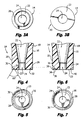
Figure 3A is a bottom view of a pipette tip of the present invention having a single groove. -
Figure 3B is a bottom view of an alternate pipette tip of the present invention having an enlarged bottom surface. -
Figure 4 is a longitudinal cross-sectional view of the tip portion of a fluid metering pipette constructed in accordance with an alternate form of the present invention. -
Figure 5 is a bottom view of the pipette tip of the present invention shown inFigure 4 . -
Figure 6 is a longitudinal cross-sectional view of the tip portion of a fluid metering pipette constructed in accordance with an alternate form of the present invention. -
Figure 7 is a bottom view of the pipette tip of the present invention shown inFigure 6 . -
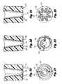
Figure 8 is a longitudinal cross-sectional view of the tip portion of a fluid metering pipette constructed in accordance with an alternate form of the present invention. -
Figure 9 is a bottom view of the pipette tip of the present invention shown inFigure 8 . -
Figure 10 is a longitudinal cross-sectional view of the tip portion of a fluid metering pipette constructed in accordance with an alternate form of the present invention. -
Figure 11 is a bottom view of the pipette tip of the present invention shown inFigure 10 . -
Figure 12 is a longitudinal cross-sectional view of the tip portion of a fluid metering pipette constructed in accordance with an alternate form of the present invention. -
Figure 13 is a bottom view of the pipette tip of the present invention shown inFigure 12 . -
Figure 14 is a longitudinal cross-sectional view of the tip portion of a fluid metering pipette constructed in accordance with an alternate form of the present invention. -
Figure 15 is a bottom view of the pipette tip of the present invention shown inFigure 14 . -
Figure 16 is a longitudinal cross-sectional view of the tip portion of a fluid metering pipette constructed in accordance with an alternate form of the present invention. -
Figure 17 is a bottom view of the pipette tip of the present invention shown inFigure 16 . -
Figure 18 is a longitudinal cross-sectional view of the tip portion of a fluid metering pipette constructed in accordance with an alternate form of the present invention. -
Figure 19 is a bottom view of the pipette tip of the present invention shown inFigure 18 . -
Figure 20 is a longitudinal cross-sectional view of the tip portion of a fluid metering pipette constructed in accordance with an alternate form of the present invention. -
Figure 21 is a bottom view of the pipette tip of the present invention shown inFigure 20 . -
Figure 22 is a longitudinal cross-sectional view of the tip portion of a fluid metering pipette constructed in accordance with an alternate form of the present invention. -
Figure 23 is a bottom view of the pipette tip of the present invention shown inFigure 22 . -
Figure 24 is a longitudinal cross-sectional view of the tip portion of a fluid metering pipette constructed in accordance with an alternate form of the present invention. -
Figure 25 is a bottom view of the pipette tip of the present invention shown inFigure 24 . -
Figure 26 is a longitudinal cross-sectional view of the tip portion of a fluid metering pipette constructed in accordance with an alternate form of the present invention. -
Figure 27 is a bottom view of the pipette tip of the present invention shown inFigure 26 . -
Figure 28 is a longitudinal cross-sectional view of the tip portion of a fluid metering pipette constructed in accordance with an alternate form of the present invention. -
Figure 29 is a bottom view of the pipette tip of the present invention shown inFigure 28 . -
Figure 30 is a longitudinal cross-sectional view of the tip portion of a fluid metering pipette constructed in accordance with an alternate form of the present invention. -
Figure 31 is a bottom view of the pipette tip of the present invention shown inFigure 30 . - The present invention is an improvement over the
conventional pipette tip 8 used in the VetTest ® veterinary blood analyzer described previously and in the aforementioned Heidt et al. patents (U.S. Patent Nos. 5,089,229 ;5,250,262 ; and5,336,467 ). - With reference to
Figures 3A-31 , the present invention includes adisposable pipette tip 14 that is fitted onto the end of theconventional pipette 2. Thepipette tip 14 has a main body that includes anupper end 18, an oppositelower end 20, asidewall 16 having an outer surface and extending between the upper and lower ends 18, 20, and acentral bore 22 extending axially therethrough. Thetip 14 converges radially inwardly from theupper end 18 toward thelower end 20, thelower end 20 being narrower in diameter than theupper end 18. Thelower end 20 has abottom surface 23 formed with acentral opening 24 which communicates with theaxial bore 22 to allow sample fluid to pass therethrough. Theupper end 18, being opposite thelower end 20, may include a plurality of radially outwardly extending supporting fins (not shown), as in the conventional pipette tip described in the Heidt et al. patents. - In accordance with the present invention, the
bottom surface 23 of thepipette tip 14 includes one or more grooves or cuts formed therein and may be enlarged. The grooves or cuts can be formed by molding, milling, stamping, cutting or other similar means. The grooves may vary in depth, shape and dimension, and may be concentric with thecentral opening 24 at thebottom surface 23 or may be spirally disposed on thebottom surface 23. Additionally, the grooves may be continuous circumferentially about thecentral opening 24, or may be intermittent, arcuate segments spaced circumferentially from each other about thecentral opening 24. Also the pipette bottom surface can be generally flat (as shown inFigures 3A-29 ) or can be convex in profile (as shown inFigures 30-31 ) with one or more grooves or other means for inhibiting radial fluid flow fromcentral opening 24. - In
Figure 3A , apipette tip 14 has preferably the same inner/outer dimensions as prior art tips (e.g.Figure 1 , opening diameter being about 0.030 inches, outer tip diameter being about 0.0685 inches) but also includesgroove 28.Comparative pipette tip 14 inFigure 3B has no groove but has an enlarged outer diameter to inhibit, impede or otherwise reduce fluid flow betweenopening 24 and the exterior oflower end 20. In a preferred embodiment, the inner diameter of opening 24 inFigure 3B is about 0.030 inches (0.762 mm) while the outer tip diameter is between about 0.069. inches (1.75 mm and about 0.115 inches 2.92 mm). - Turning to
Figures 4 and 5 , thebottom surface 23 of thelower end 20 of the pipette tip, in accordance with one embodiment of the present invention, may have one or more similarly dimensioned, triangular or V-shaped grooves 28 (when viewed in cross-section) cut in thebottom surface 23, concentrically disposed (or spirally disposed) about thecentral opening 24. The triangular groove orgrooves 28 may have twoopposite sidewalls 30 separated by an angle of preferably about sixty-five (65) degrees that diverge from the apex of the groove to form anopening 32 of preferably about 0.0080 inches (0.203 mm) in thebottom surface 23. Thetriangular groove 28 may be cut into thebottom surface 23 to a variety of depths, but is preferably cut to a depth of about 0.0063 inches (0.16 mm). If onegroove 28 is used, as shown inFigures 4 and 5 , the radially inner edge of thegroove opening 32 formed in thebottom surface 23 is preferably at a radius of about 0.0355 inches (0.902 mm) from the center of thepipette tip 14. - In another embodiment of the present invention, as illustrated in
Figures 6 and 7 , thebottom surface 23 of thelower end 20 of the pipette tip may have one or more square shaped grooves 34 (when viewed in cross-section) cut in thebottom surface 23, concentrically disposed (or spirally disposed) about thecentral opening 24. The square groove orgrooves 34 may include a recessedupper wall 36, twolateral sidewalls 38 and anopening 40 in thebottom surface 23. The twosidewalls 38 are preferably separated by about 0.0080 inches (0.203 mm). Like the previous embodiment of the present invention shown inFigures 4 and 5 , the square groove orgrooves 34 may be cut into thebottom surface 23 to a variety of depths, but is preferably cut to a depth of about 0.0060 inches (0.152 mm). If onegroove 34 is used, as shown inFigures 6 and 7 , the radially inner edge at thegroove opening 40 formed in thebottom surface 23 is preferably at a radius of about 0.0355 inches (0.902 mm) from the center of thepipette tip 14. - In yet another form of the present invention, as illustrated in
Figures 8 and 9 , thebottom surface 23 may have a plurality of differently dimensioned, triangular or V-shaped grooves (preferably two), cut in thebottom surface 23 of the pipette tip, concentrically disposed about thecentral opening 24. A radially outertriangular groove 42 may have twoopposite sidewalls 44 separated by an angle of preferably about sixty-five (65) degrees that diverge from the apex of thegroove 42 to form anopening 46 of preferably about 0.0076 inches (0.193 mm) in thebottom surface 23. The outertriangular groove 42 may be cut into thebottom surface 23 to a variety of depths, but is preferably cut to a depth of about 0.0060 inches (0.152 mm). A radially innertriangular groove 48 may have twoopposite sidewalls 50 separated by an angle of preferably about sixty-five (65) degrees that diverge from the apex of thegroove 48 to form anopening 52 of preferably about 0.0062 (0.157 mm) inches in thebottom surface 23. The innertriangular groove 48 may be cut into thebottom surface 23 to a variety of depths, but is preferably cut to a depth of about 0.0048 inches (0.122 mm). The radially inner edge ofouter groove opening 46 formed in thebottom surface 23 is preferably at a radius of about 0.0361 inches (0.917 mm) from the center of thepipette tip 14, and the radially inner edge ofinner groove opening 52 formed in thebottom surface 23 is preferably at a radius of about 0.0232 inches (0.589 mm) also measured from the center of thepipette tip 14. - In each of the embodiments of the present invention described above and shown in
Figures 4-9 , thelower end 20 andbottom surface 23 thereof was enlarged to accommodate the groove or grooves, and preferably has an outer diameter of about 0.0970 inches (2.46 mm). Thecentral opening 24 preferably has a diameter of about 0.0310 inches (0.787 mm). However, as shown inFigure 3A , enlargement ofbottom surface 23 is not required - A further form of the present invention is illustrated in
Figures 10 and 11 of the drawings. In this embodiment, thebottom surface 23 includes one or more similarly dimensioned, triangular or V-shaped grooves 28 (when viewed in cross-section) formed in thebottom surface 23, and concentrically disposed about thecentral opening 24. This embodiment is similar to that shown inFigures 4 and 5 , except that the dimensions of thebottom surface 23, thecentral opening 24 and the V-shaped grooves are different. - More specifically, the triangular groove or
grooves 28 may have twoopposite sidewalls 30 separated by an angle of preferably about ninety (90) degrees that diverge from the apex of the groove to form anopening 32 of preferably about 0.0100 inches (0.254 mm) in thebottom surface 23. Thetriangular groove 28 may be cut into thebottom surface 23 to a depth of about 0.0050 inches (0.127 mm). - In the embodiment of the present invention illustrated in
Figures 10 and 11 of the drawings, the radius of thetip opening 24 is preferably about 0.0150 inches (0.381 mm); and the outer periphery of thebottom surface 23 has a radius of about 0.0525 inches (1.33 mm). The inner edge of theopening 32 of the innermost groove preferably has a radius of about 0.0225 inches (0.527 mm), and the inner edge of theopening 32 of the outermost groove preferably has a radius of about 0.0350 inches (0.889 mm). -
Figures 12 and 13 illustrate another embodiment of the pipette tip of the present invention which is similar in many respects to the embodiment of the pipette tip shown inFigures 10 and 11 ; however, the dimensions of the embodiment shown inFigures 12 and 13 differ from those of the embodiment shown inFigures 10 and 11 . - More specifically, and referring to
Figures 12 and 13 of the drawings, the pipette tip is preferably formed with acentral opening 24 in itsbottom surface 23 having a preferred radius of about 0.0150 inches (0.381 mm) as in the embodiments shown inFigures 10 and 11 , but the outer radius of thebottom surface 23 of the pipette tip differs from that shown inFigures 10 and 11 in that thebottom surface 23 has a preferred outer diameter of about 0.0575 inches (1.46 mm). Also, the dimensions of the V-shaped ortriangular grooves 28 formed concentrically in thebottom surface 23 of the pipette tip are substantially the same as those of the embodiment illustrated inFigures 10 and 11 of the drawings; however, the inner edge of theopening 32 defined in thebottom surface 23 of the innermost groove preferably has a radius of about 0.0250 inches (0.635 mm), and the inner edge of theopening 32 defined in thebottom surface 23 by the outermost groove preferably has a radius of about 0.0375 inches (0.953 mm). -
Figures 14 and 15 illustrate another embodiment of the pipette tip of the present invention in which one or moredeeper grooves 28, which are preferably triangular or V-shaped in cross-section, are formed in thebottom surface 23 of the pipette tip and concentrically disposed about thecentral opening 24. More specifically, the triangular groove orgrooves 28 may have twoopposite sidewalls 30 separate by an angle of preferably about twenty-three (23) degrees that diverge from the apex of the groove to form anopening 32 of preferably about 0.008 inches (0.203 mm) in thebottom surface 23. The triangular groove orgrooves 28 are preferably cut into thebottom surface 23 to a depth of about 0.020 inches (0.508 mm). - In the embodiment of the present invention illustrated in
Figures 14 and 15 of the drawings, the diameter of thetip opening 24 is preferably about 0.030 inches (0.762 mm), and the outer periphery of thebottom surface 23 has a diameter of about 0.105 inches (2.67 mm). The inner edge of theopening 32 of the innermost groove preferably has a radius of about 0.024 inches (0.61 mm), and the inner edge of theopening 32 of the outermost groove preferably has a radius of about 0.036 inches (0.914 mm). -
Figures 16 and 17 illustrate yet another embodiment of the pipette tip of the present invention which is similar in many respects to the embodiment of the pipette tip shown inFigures 14 and 15 . The outer diameter of thebottom surface 23 is preferably about 0.115 inches (2.92 mm), while the diameter of thetip opening 24 is preferably about 0.030 inches (0.762 mm). Again, one or more triangular grooves 28 (when viewed in cross-section) are formed in thebottom surface 23 and are concentrically disposed about thecentral opening 24. The triangular groove orgrooves 28 have twoopposite sidewalls 30 separated by an angle of preferably about twenty-three (23) degrees that diverge from the apex of the groove to form anopening 32 of preferably about 0.008 inches (0.203 mm) in thebottom surface 23. The triangular groove orgrooves 28 are preferably cut into thebottom surface 23 to a depth of about 0.020 inches (0.508 mm). - In the embodiment shown in
Figures 16 and 17 of the drawings, the inner edge of theopening 32 of the innermost groove preferably has a radius of about 0.026 inches (0.66 mm), and the inner edge of theopening 32 of the outermost groove preferably has a radius of about 0.038 inches (0.965 mm). -
Figures 18 and 19 illustrate yet another embodiment of the pipette tip formed in accordance with the present invention. In this embodiment, adrip edge 70 is included which surrounds the periphery of thebottom surface 23 and extends outwardly axially therefrom. Preferably, thedrip edge 70 has a radial width of about 0.0100 inches (0.254 mm), and extends from thebottom surface 23 of the pipette tip a distance of about 0.0050 inches (0.127 mm). - In the embodiment shown in
Figures 18 and 19 , a triangular or V-shapedgroove 28 is formed in thebottom surface 23 and is concentrically disposed about thecentral opening 24. Thetriangular groove 28 has twoopposite sidewalls 30 separated by an angle of preferably about ninety (90) degrees that diverge from the apex of the groove to form anopening 32 of preferably about 0.0100 inches (0.254 mm) in thebottom surface 23. Thetriangular groove 28 is preferably cut into thebottom surface 23 to a depth of about 0.0050 inches (0.127 mm). - In the embodiment of the pipette tip shown in the
Figures 18 and 19 , the radius of thetip opening 24 is preferably about 0.0150 inches (0.381 mm), and the outer diameter of thebottom surface 23 is about 0.1050 inches (2.67 mm). The inner edge of theopening 32 of thegroove 28 preferably has a radius of about 0.0250 inches (0.635mm), and the radially inner edge of thedrip edge 70 preferably has a radius of about 0.0425 inches (1.08 mm). Thegroove 28 and thedrip edge 70 increase the effective surface area of thebottom surface 23 of the pipette tip between thecentral opening 24 and the outer edge of thebottom surface 23 to inhibit the flow of fluid passing through thecentral opening 24 of the pipette tip toward the outer edge of thebottom surface 23 and thereby minimizes the possibility of the fluid from traveling up the outer surface of the sidewall of the pipette tip. -
Figures 20 and 21 illustrate yet another embodiment of the pipette tip of the present invention, in which one or more half-round or semi-circular (in cross-section)grooves 72 are formed in thebottom surface 23 of the pipette tip. Again, the half-round grooves 72 may be concentrically disposed about thecentral opening 24, or may be non-concentrically disposed or spirally disposed about the central opening, -
Figures 22 and 23 illustrate a form of the pipette tip of the present invention in which agroove 28 is formed in thebottom surface 23 of the pipette tip and spirally disposed thereon about thecentral opening 24. -
Figures 24 and 25 illustrate a pipette tip formed in accordance with another form of the present invention, in which agroove 28 is formed in thebottom surface 23 of the tip and is disposed thereon about thecentral opening 24 in a serpentine direction with portions thereof extending partially radially inwardly and outwardly on the bottom surface of the pipette tip. The purpose of such aserpentine groove 28, as is the purpose with the grooves formed in thebottom surface 23 of the pipette tip described previously and shown inFigures 4-23 , is to increase the effective surface area of thebottom surface 23 of the pipette tip, which inhibits the flow of the plasma/serum fluid from thecentral opening 24 therealong toward the outer surface of the pipette tip in order to minimize the chance of the fluid sample traveling up the outer surface of the sidewall of the pipette tip. - Another form of a pipette tip constructed in accordance with the present invention is illustrated by
Figures 26 and 27 . Here, one ormore grooves 28 formed in thebottom surface 23 of the pipette tip may extend radially from thecentral opening 24 to the outer edge of thebottom surface 23. Again, theradial grooves 28 increase the overall surface area of thebottom surface 23 of the pipette tip, thus inhibiting the flow of sample fluid from the central opening to the outer edge of the bottom surface, where it may have otherwise traveled up the outer surface of the sidewall of the pipette tip and possibly affect the accuracy of the volume of fluid dispensed on a reagent test slide. - Heretofore, grooves have been described as being formed in the
bottom surface 23 of the pipette tip. However, it should be realized that the bottom surface may take on other shapes and features which increase the effective surface area of thebottom surface 23 and thus inhibit the flow of sample fluid from thecentral opening 24 to the outer edge of thebottom surface 23 of the pipette tip. For example, and as shown inFigures 28 and 29 of the drawings, one ormore protrusions 74, which may be triangular, rectangular or semi-circular in cross-sectional shape, may be formed on thebottom surface 23 of the pipette tip and extend outwardly therefrom.Such protrusions 74 may be spirally disposed, concentrically disposed or non-concentrically disposed on thebottom surface 23 about thecentral opening 24 formed in the pipette tip.Such protrusions 74 increase the effective surface area of the pipette tip and thus inhibit the flow of sample fluid from thecentral opening 24 to the outer edge of thebottom surface 23. - In addition, the
bottom surface 23 of the pipette tip of the present invention, with or without grooves, may be convex in shape, to extend axially outwardly from the underside of the pipette tip, as illustrated byFigures 30 and 31 of the drawings. The convex shape of thebottom surface 23 of the pipette tip effectively increases the overall surface area of thebottom surface 23 of the pipette tip, thus inhibiting the flow of sample fluid from thecentral opening 24 to the outer edge of thebottom surface 23 to minimize the possibility of the fluid reaching the outer edge of thebottom surface 23 and traveling up the outer surface of the sidewall of the pipette tip. The convex shaped tip also serves to reduce the volume of fluid that could remain adherent to the pipette tip. For example, if the test slide upon which the fluid is being dispensed has a tendency to repel the fluid, the convex shape decreases the likelihood that an undesirable amount of fluid remains on the tip after application. - The addition of grooves or protrusions formed in the
bottom surface 23 of thepipette tip 14 of the present invention, or increasing the overall surface area of the bottom surface, reduces the infrequent problem of spot failure due to the imprecise sample volume dispensing occurring in the conventional pipette design, as the grooves, protrusions or increased surface area inhibit the droplet passing through the opening 24 from flowing towards the outer surface of thesidewall 16 of thepipette tip 14 and traveling up the pipette tip outer surface. A more precise metering of fluid onto the chemical reagent test slide (or into a vial containing a chemical reagent) is realized by the pipette tip of the present invention, even while the pipette tip of the present invention is made from the preferred material, polypropylene, which has an affinity for some fluids, such as blood serum and plasma. - In addition, while the preferred embodiments have primarily been discussed as relating to blood chemical analyzers, clearly one skilled in the art of dispensing fluids will appreciate that the present invention has applications outside this field.
Claims (13)
- A pipette tip (14) comprising a main body having an upper end (18), a lower end (20) disposed axially opposite the upper end (18) and a sidewall (16) extending between the upper end (18) and the lower end (20), the sidewall (16) including an outer surface, the main body having formed therein a bore (22) extending axially therethrough between the upper end (18) and the lower end (20), the lower end (20) having a bottom surface (23), the bottom surface (23) having an opening (24) formed through the thickness thereof which is in communication with the axial bore (22) to allow the passage of fluid therethrough,
characterized in that the bottom surface (23) further having means for inhibiting fluid passing through the opening (24) from flowing towards the outer surface of the sidewall (16) of the pipette tip (14),
wherein the means for inhibiting fluid from flowing towards the outer surface of the sidewall (16) of the pipette tip (14) include one or more grooves (28, 34, 42, 48) formed in the bottom surface (23) of the main body of the pipette tip (14). - The pipette tip (14) according to claim 1,
characterized in that the one or more grooves (28, 34, 42, 48) are V-shaped in cross-section, rectangular in cross-section or semi-circular in cross-section, or are concentrically disposed, spirally disposed, radially disposed, or disposed in a serpentine configuration, on the bottom surface (23) about the opening (24). - The pipette tip (14) according to claim 1,
characterized in that the one or more grooves (28, 34, 42, 48) include at least a first groove (28, 34, 42, 48) and a second groove (28, 34, 42, 48) formed in the
bottom surface (23) of the main body of the pipette tip (14), the at least first and second grooves (28, 34, 42, 48) having similar shapes in cross-section. - The pipette tip (14) according to claim 3,
characterized in that the at least first and second grooves (28, 34, 42, 48) are concentrically disposed about the opening (24). - The pipette tip (14) according to claim 3,
characterized in that the at least first and second grooves (28, 34, 42, 48) are spirally disposed about the opening (24). - The pipette tip (14) according to claim 1,
characterized in that the one or more grooves (28, 34, 42, 48) include at least a first groove (28, 34, 42, 48) and a second groove (28, 34, 42, 48) formed in the bottom surface (23) of the main body of the pipette tip (14), the first groove (28, 34, 42, 48) being situated on the bottom surface (23) radially inwardly of the second groove (28, 34, 42, 48), the first groove (28, 34, 42, 48) having a first cross-sectional dimension, the second groove (28, 34, 42, 48) having a second cross-sectional dimension, the first cross-sectional dimension of the first groove (28, 34, 42, 48) being different from the second cross-sectional dimension of the second groove (28, 34, 42, 48). - The pipette tip (14) according to claim 6,
characterized in that the first and second grooves (28, 34, 42, 48) are concentrically disposed about the opening (24). - The pipette tip (14) according to claim 6,
characterized in that the first cross-sectional dimension of the first groove (28, 34, 42, 48) is less than the second cross-sectional dimension of the second groove (28, 34, 42, 48). - The pipette tip (14) according to claim 1,
characterized in that the one or more grooves (28, 34, 42, 48) are continuous and circular in shape. - The pipette tip (14) according to any of claims 1 to 9,
characterized in that the means for inhibiting fluid passing through the opening (24) from flowing towards the outer surface of the sidewall (16) of the pipette tip (14) comprise an increase in material between the opening (24) and the outer surface of the sidewall (16) of the pipette tip (14). - The pipette tip (14) according to any of claims 1 to 9,
characterized in that the means for inhibiting fluid passing through the opening (24) from flowing towards the outer surface of the sidewall (16) of the pipette tip (14) include a bottom surface (23) of the pipette tip (14) that is flat or convex. - The pipette tip (14) according to any of claims 1 to 9,
characterized in that the means for inhibiting fluid passing through the opening (24) from flowing towards the outer surface of the sidewall (16) of the pipette tip (14) include at least one protrusion (70, 74) situated on the bottom surface (23) and extending outwardly therefrom. - A pipette tip (14) according to claim 12,
characterized in that the at least one protrusion (70, 74) is continuous and circular in shape.
Applications Claiming Priority (3)
| Application Number | Priority Date | Filing Date | Title |
|---|---|---|---|
| US85930806P | 2006-11-16 | 2006-11-16 | |
| US11/985,439 US7794664B2 (en) | 2006-11-16 | 2007-11-15 | Pipette tip |
| PCT/US2007/024035 WO2008063544A2 (en) | 2006-11-16 | 2007-11-16 | Pipette tip |
Publications (3)
| Publication Number | Publication Date |
|---|---|
| EP2091649A2 EP2091649A2 (en) | 2009-08-26 |
| EP2091649A4 EP2091649A4 (en) | 2011-06-29 |
| EP2091649B1 true EP2091649B1 (en) | 2012-10-17 |
Family
ID=39430325
Family Applications (1)
| Application Number | Title | Priority Date | Filing Date |
|---|---|---|---|
| EP07867477A Not-in-force EP2091649B1 (en) | 2006-11-16 | 2007-11-16 | Pipette tip |
Country Status (7)
| Country | Link |
|---|---|
| US (1) | US7794664B2 (en) |
| EP (1) | EP2091649B1 (en) |
| JP (1) | JP5466947B2 (en) |
| AU (1) | AU2007322064B2 (en) |
| CA (1) | CA2668767C (en) |
| ES (1) | ES2397544T3 (en) |
| WO (1) | WO2008063544A2 (en) |
Families Citing this family (22)
| Publication number | Priority date | Publication date | Assignee | Title |
|---|---|---|---|---|
| EP2153900B1 (en) * | 2008-07-30 | 2015-09-02 | F. Hoffmann-La Roche AG | Pipette tip and use of the pipette tip |
| US9017991B2 (en) | 2009-03-13 | 2015-04-28 | Tufts University | Methods tip assemblies and kits for introducing material into cells |
| US9470616B2 (en) | 2009-04-27 | 2016-10-18 | E.I. Spectra, Llc | Pipette instrument |
| USD663042S1 (en) * | 2010-01-22 | 2012-07-03 | Biotix, Inc. | Pipette tip |
| US9486803B2 (en) * | 2010-01-22 | 2016-11-08 | Biotix, Inc. | Pipette tips |
| USD679828S1 (en) * | 2010-01-22 | 2013-04-09 | Biotix, Inc. | Pipette tip |
| US9962692B2 (en) | 2010-08-31 | 2018-05-08 | Canon U.S. Life Sciences, Inc. | Methods, devices, and systems for fluid mixing and chip interface |
| US8540911B2 (en) | 2010-11-16 | 2013-09-24 | Miniplast Ein-Shemer ACS Ltd. | Methods of manufacturing polymer pipettes |
| CA2825612C (en) | 2011-01-24 | 2021-02-16 | Nils B. Adey | Devices, systems, and methods for extracting a material from a material sample |
| USD687562S1 (en) * | 2012-03-19 | 2013-08-06 | Biotix, Inc. | Pipette tip |
| US8795606B2 (en) | 2012-05-30 | 2014-08-05 | Biotix, Inc. | Integrated pipette tip devices |
| DE102012214426B3 (en) * | 2012-08-14 | 2013-08-01 | Aptar Radolfzell Gmbh | dropper |
| CN107209092A (en) | 2015-01-31 | 2017-09-26 | 豪夫迈·罗氏有限公司 | Systems and methods for intermediate dissection |
| WO2016120434A1 (en) | 2015-01-31 | 2016-08-04 | Roche Diagnostics Gmbh | Systems and methods for meso-dissection |
| EP4027127B1 (en) * | 2015-04-08 | 2024-07-31 | Becton, Dickinson and Company | Method for collecting microbial growth from a semi-solid surface |
| JP6572078B2 (en) | 2015-09-28 | 2019-09-04 | 富士フイルム株式会社 | Pipette tip and liquid injection method |
| CH712735A1 (en) * | 2016-07-22 | 2018-01-31 | Tecan Trading Ag | Pipetting device with a liquid volume sensor and liquid processing system. |
| WO2018087155A1 (en) | 2016-11-09 | 2018-05-17 | F. Hoffmann-La Roche Ag | Automated tissue dissection instrument and methods of using the same |
| EP3624946B1 (en) | 2017-05-17 | 2025-03-19 | Biotix, Inc. | Ergonomic pipette tips |
| USD905865S1 (en) * | 2018-05-11 | 2020-12-22 | Biotix, Inc. | Pipette tip |
| JP7111037B2 (en) * | 2019-03-15 | 2022-08-02 | コニカミノルタ株式会社 | Reactor and reaction method |
| WO2022165536A1 (en) * | 2021-02-01 | 2022-08-04 | Bio-Rad Laboratories, Inc. | Microfluidic probes |
Family Cites Families (78)
| Publication number | Priority date | Publication date | Assignee | Title |
|---|---|---|---|---|
| FR2295405A1 (en) | 1974-10-29 | 1976-07-16 | Marteau D Autry Eric | CALIBRATE PIPETTE |
| US4347875A (en) | 1980-07-14 | 1982-09-07 | Eastman Kodak Company | Self-cleaning nozzle construction for aspirators |
| US4325913A (en) | 1980-10-20 | 1982-04-20 | Coulter Electronics, Inc. | Reagent probe and method for fabrication thereof |
| DE3125321C2 (en) | 1981-06-27 | 1985-06-05 | Bodenseewerk Perkin-Elmer & Co GmbH, 7770 Überlingen | Piercing cannula for taking samples |
| US4483825A (en) | 1982-07-09 | 1984-11-20 | Fatches Keith R | Pipette and filter combination |
| IT1153640B (en) | 1982-11-05 | 1987-01-14 | Italiana L P Spa | APPARATUS FOR THE MEASUREMENT OF THE SPEED OF ERITROSEDIMENTATION OF THE BLOOD |
| US4616514A (en) | 1983-06-06 | 1986-10-14 | Rainin Instrument Co., Inc. | Replaceable tip assembly for pipette |
| JPS6323749A (en) * | 1986-03-31 | 1988-02-01 | Koryo Kagaku Kogyo Kk | Pipet tip |
| US4748859A (en) | 1987-03-06 | 1988-06-07 | Rainin Instrument Co., Inc. | Disposable pipette tip |
| DE3824767A1 (en) | 1988-07-21 | 1990-02-01 | Eppendorf Geraetebau Netheler | CLIP-ON PIPETTE TIP IN THE FORM OF A CORRESPONDING HEAD PIECE, IN PARTICULAR CONE OF A PIPETTE, AT LEAST IN PARTIAL CONTAINERS |
| US4988481A (en) | 1989-01-30 | 1991-01-29 | Labsystems Oy | Electrical pipette |
| US4971763A (en) | 1989-02-14 | 1990-11-20 | Eastman Kodak Company | Liquid-controlling nozzle geometry for dispensers of liquids |
| JPH03131351A (en) * | 1989-10-16 | 1991-06-04 | Fuji Photo Film Co Ltd | Pipette tip subjected to water-repellent treatment |
| US5089229A (en) | 1989-11-22 | 1992-02-18 | Vettest S.A. | Chemical analyzer |
| US5250262A (en) | 1989-11-22 | 1993-10-05 | Vettest S.A. | Chemical analyzer |
| JPH0690215B2 (en) * | 1989-12-08 | 1994-11-14 | 株式会社東芝 | Dispensing nozzle |
| US5026526A (en) | 1990-02-09 | 1991-06-25 | Eastman Kodak Company | Automated capping means for analyzer pipette |
| US4982577A (en) | 1990-03-19 | 1991-01-08 | I.Q.F. Inc. | Cryogenic apparatus |
| US5200151A (en) | 1990-05-21 | 1993-04-06 | P B Diagnostic Systems, Inc. | Fluid dispensing system having a pipette assembly with preset tip locator |
| US5217693A (en) | 1990-05-29 | 1993-06-08 | Mark Anderson | Embryo washing apparatus and process |
| US5073347A (en) | 1990-07-17 | 1991-12-17 | Beral Enterprises, Inc. | Unitary volumetric pipette and method for making the same |
| US5121642A (en) | 1990-12-19 | 1992-06-16 | Eastman Kodak Company | Liquid sampling method and apparatus |
| US5192511A (en) | 1991-05-31 | 1993-03-09 | Tri-Continent Scientific, Inc. | Pipette tip and piston |
| US5212992A (en) | 1991-06-14 | 1993-05-25 | Medical Laboratory Automation, Inc. | Capacitive probe sensor with reduced effective stray capacitance |
| US5159842A (en) * | 1991-06-19 | 1992-11-03 | Eastman Kodak Company | Self-cleaning pipette tips |
| JPH04372862A (en) * | 1991-06-24 | 1992-12-25 | Fuji Photo Film Co Ltd | Automatic apparatus for distribution |
| US5232669A (en) * | 1991-11-08 | 1993-08-03 | Abbott Laboratories | Pipette tip with self-aligning and self-sealing features |
| US5218875A (en) | 1992-01-13 | 1993-06-15 | Volpe Stephen J | Combination glass/plastic pipet tip assembly |
| US5354537A (en) | 1992-04-27 | 1994-10-11 | Akzo N.V. | Piercing and sampling probe |
| US5260030A (en) | 1992-06-03 | 1993-11-09 | Bio-Plas, Inc. | Calibrated pipette tip and method |
| DE69305947T2 (en) | 1992-09-18 | 1997-03-13 | Amersham Int Plc | Device and method for affinity separation |
| US5324480A (en) | 1992-12-04 | 1994-06-28 | Hamilton Company | Liquid handling system |
| US5468453A (en) | 1993-06-14 | 1995-11-21 | Cirrus Diagnostics, Inc. | Low carryover pipette probe |
| US5550059A (en) | 1994-02-23 | 1996-08-27 | Bayer Corporation | Fluid sensing pipette |
| JPH07284674A (en) * | 1994-04-20 | 1995-10-31 | Fuji Photo Film Co Ltd | Pipette tip |
| JPH08112537A (en) * | 1994-10-17 | 1996-05-07 | Hitachi Ltd | Pipette tip |
| US5918291A (en) | 1995-06-07 | 1999-06-29 | Inacu; Fulga | Method for liquid aspiration from a sealed container |
| JP3699749B2 (en) | 1995-06-09 | 2005-09-28 | セーラー万年筆株式会社 | pipette |
| JP3158054B2 (en) | 1996-07-19 | 2001-04-23 | 株式会社日立製作所 | Liquid sampling device |
| US5807524A (en) | 1996-08-06 | 1998-09-15 | Rainin Instrument Co., Inc. | Pipette tip with pipette surface contamination protector |
| US6066297A (en) | 1997-01-03 | 2000-05-23 | Matrix Technologies Corporation | Small sample volume displacement pipette tips |
| US6203083B1 (en) | 1997-01-30 | 2001-03-20 | Siemens Aktiengesellschaft | Sucking pipette for picking up electric components |
| USD401698S (en) | 1997-01-31 | 1998-11-24 | Becton Dickinson And Company | Multistage pipet |
| US6045759A (en) | 1997-08-11 | 2000-04-04 | Ventana Medical Systems | Fluid dispenser |
| US6260407B1 (en) | 1998-04-03 | 2001-07-17 | Symyx Technologies, Inc. | High-temperature characterization of polymers |
| US6551557B1 (en) | 1998-07-07 | 2003-04-22 | Cartesian Technologies, Inc. | Tip design and random access array for microfluidic transfer |
| GB9824202D0 (en) * | 1998-11-04 | 1998-12-30 | Moore David F | Liquid transfer system |
| US6248295B1 (en) | 1998-11-06 | 2001-06-19 | Rainin Instrument Co., Inc. | Pipette with improved pipette tip and mounting shaft combination |
| US6197259B1 (en) | 1998-11-06 | 2001-03-06 | Rainin Instrument Co., Inc. | Easy eject pipette tip |
| US6299841B1 (en) | 1999-03-05 | 2001-10-09 | Rainin Instrument Co., Inc. | Bilaterally symmetrical battery powered microprocessor controlled lightweight hand-holdable electronic pipette |
| JP2000297761A (en) * | 1999-04-14 | 2000-10-24 | Hitachi Ltd | Micro pump and chemical analyzer |
| DE19917375C2 (en) | 1999-04-16 | 2001-09-27 | Hamilton Bonaduz Ag Bonaduz | Pipetting unit |
| DE19919305A1 (en) | 1999-04-28 | 2000-11-02 | Roche Diagnostics Gmbh | Method and device for liquid transfer with an analysis device |
| US6716396B1 (en) | 1999-05-14 | 2004-04-06 | Gen-Probe Incorporated | Penetrable cap |
| US6814936B1 (en) | 1999-07-01 | 2004-11-09 | Goran Enhorning | Pipette assembly having a small volume disposable tip |
| US6280689B1 (en) | 1999-07-27 | 2001-08-28 | Becton Dickinson And Company | Dripless pipet |
| ATE289872T1 (en) | 1999-10-21 | 2005-03-15 | Tecan Trading Ag | DELIVERY OR PIPETTING DEVICE WITH REPLACEABLE PIPETTE TIP |
| US6532837B1 (en) | 2000-02-03 | 2003-03-18 | Rainin Instrument, Llc | Pipette device with tip ejector utilizing stored energy |
| DE10004941A1 (en) | 2000-02-06 | 2001-08-09 | Reimer Offen | Tempered liquid sampler |
| US6566145B2 (en) | 2000-02-09 | 2003-05-20 | William E Brewer | Disposable pipette extraction |
| US6428750B1 (en) | 2000-02-17 | 2002-08-06 | Rainin Instrument, Llc | Volume adjustable manual pipette with quick set volume adjustment |
| JP4576502B2 (en) | 2000-04-07 | 2010-11-10 | アークレイ株式会社 | Multiple pipette |
| FR2807343B1 (en) | 2000-04-07 | 2002-12-06 | Gilson Sa | COLLECTION PIPETTE PROVIDED WITH MEANS FOR ADJUSTING THE VOLUME TO BE COLLECTED |
| JP2002001136A (en) * | 2000-06-16 | 2002-01-08 | Internatl Reagents Corp | nozzle |
| US6749812B2 (en) | 2000-06-26 | 2004-06-15 | Vistalab Technologies | Automatic pipette detipping |
| FI20002241A0 (en) | 2000-10-11 | 2000-10-11 | Labsystems Oy | Adjustable pipette |
| US6824024B2 (en) | 2000-11-17 | 2004-11-30 | Tecan Trading Ag | Device for the take-up and/or release of liquid samples |
| US6343717B1 (en) | 2000-11-21 | 2002-02-05 | Jack Yongfeng Zhang | Pre-filled disposable pipettes |
| US6596240B2 (en) * | 2001-01-12 | 2003-07-22 | Porex Corporation | Pipette tip for easy mounting and ejecting from a pipette |
| AUPR605601A0 (en) | 2001-07-03 | 2001-07-26 | Blackwood, Miles | Pipeite of sandwich construction |
| US6605159B2 (en) | 2001-08-30 | 2003-08-12 | Micron Technology, Inc. | Device and method for collecting and measuring chemical samples on pad surface in CMP |
| US6457612B1 (en) | 2001-10-12 | 2002-10-01 | Amphastar Pharmaceuticals Inc. | Sealable and manipulable pre-filled disposable pipette |
| JP4148894B2 (en) | 2001-10-16 | 2008-09-10 | マトリックス・テクノロジイズ・コーポレーション | Hand-held pipette |
| US6955077B2 (en) | 2002-05-09 | 2005-10-18 | Quality Scientific Plastics, Inc. | Pipette tip with an internal sleeve and method for forming same |
| FR2845933B1 (en) | 2002-10-16 | 2005-02-11 | Articles De Laboratoire De Pre | LABORATORY PIPETTE COMPRISING A BRAID OF SYNTHETIC FIBER YARNS OF A COLOR CORRESPONDING TO AT LEAST ONE CHARACTERISTIC OF THE PIPETTE |
| JP4135796B2 (en) * | 2002-11-20 | 2008-08-20 | 株式会社テクノス | Scan / collection nozzle |
| US7320259B2 (en) | 2004-03-06 | 2008-01-22 | Medax International, Inc. | Pipette tip for easy separation |
| US7077018B2 (en) | 2004-04-27 | 2006-07-18 | Vertex Pharmaceuticals, Inc. | Cleanable volume displacement pipetter |
-
2007
- 2007-11-15 US US11/985,439 patent/US7794664B2/en active Active
- 2007-11-16 JP JP2009537214A patent/JP5466947B2/en not_active Expired - Fee Related
- 2007-11-16 AU AU2007322064A patent/AU2007322064B2/en not_active Ceased
- 2007-11-16 CA CA2668767A patent/CA2668767C/en not_active Expired - Fee Related
- 2007-11-16 WO PCT/US2007/024035 patent/WO2008063544A2/en not_active Ceased
- 2007-11-16 ES ES07867477T patent/ES2397544T3/en active Active
- 2007-11-16 EP EP07867477A patent/EP2091649B1/en not_active Not-in-force
Also Published As
| Publication number | Publication date |
|---|---|
| CA2668767A1 (en) | 2008-05-29 |
| JP5466947B2 (en) | 2014-04-09 |
| EP2091649A2 (en) | 2009-08-26 |
| AU2007322064B2 (en) | 2013-07-25 |
| US20080131326A1 (en) | 2008-06-05 |
| US7794664B2 (en) | 2010-09-14 |
| WO2008063544A3 (en) | 2008-08-21 |
| WO2008063544A2 (en) | 2008-05-29 |
| AU2007322064A1 (en) | 2008-05-29 |
| JP2010510488A (en) | 2010-04-02 |
| CA2668767C (en) | 2014-06-03 |
| EP2091649A4 (en) | 2011-06-29 |
| ES2397544T3 (en) | 2013-03-07 |
Similar Documents
| Publication | Publication Date | Title |
|---|---|---|
| CA2668767C (en) | Pipette tip | |
| US4347875A (en) | Self-cleaning nozzle construction for aspirators | |
| US5770151A (en) | High-speed liquid deposition device for biological molecule array formation | |
| AU742823B2 (en) | Capillary active test element having an intermediate layer situated between the support and the covering | |
| US7258253B2 (en) | Method and system for precise dispensation of a liquid | |
| US3783696A (en) | Automatic volume control pipet | |
| EP0701865A1 (en) | Spotting tip | |
| US4971763A (en) | Liquid-controlling nozzle geometry for dispensers of liquids | |
| EP1685901A1 (en) | Liquid sampling utilizing ribbed pipette tip for barrier penetration | |
| EP1685902A1 (en) | Liquid sampling utilizing ribbed pipette tip for barrier penetration | |
| JPS60137443A (en) | Throw-away pipette chip | |
| US8460617B2 (en) | Pipette tip and a method for pipetting a congealed blood sample utilizing the pipette tip | |
| JP2001525552A (en) | Capillary liquid transport device | |
| US20230064079A1 (en) | Pipette tip with two positive angle steps | |
| US7201880B1 (en) | Sample dispenser | |
| WO2018160979A1 (en) | Evaporation-limiting inserts for reagent containers and related methods of use | |
| JP2013011577A (en) | System and method for dispensing fluid from container into fluid receptacle | |
| US6280689B1 (en) | Dripless pipet | |
| JP2006208373A (en) | Liquid sampling utilizing ribbed pipette tip for barrier penetration | |
| US11724262B2 (en) | Method of facilitating the handling of a volume of fluid | |
| JPH08112537A (en) | Pipette tip | |
| US20050196319A1 (en) | System and method for providing a reaction surface of a predetermined area for a limited volume | |
| WO2024247692A1 (en) | Nozzle | |
| JP2025101604A (en) | nozzle | |
| US8585984B2 (en) | Proboscis for use with a diagnostic instrument |
Legal Events
| Date | Code | Title | Description |
|---|---|---|---|
| PUAI | Public reference made under article 153(3) epc to a published international application that has entered the european phase |
Free format text: ORIGINAL CODE: 0009012 |
|
| 17P | Request for examination filed |
Effective date: 20090608 |
|
| AK | Designated contracting states |
Kind code of ref document: A2 Designated state(s): AT BE BG CH CY CZ DE DK EE ES FI FR GB GR HU IE IS IT LI LT LU LV MC MT NL PL PT RO SE SI SK TR |
|
| DAX | Request for extension of the european patent (deleted) | ||
| A4 | Supplementary search report drawn up and despatched |
Effective date: 20110526 |
|
| GRAP | Despatch of communication of intention to grant a patent |
Free format text: ORIGINAL CODE: EPIDOSNIGR1 |
|
| GRAS | Grant fee paid |
Free format text: ORIGINAL CODE: EPIDOSNIGR3 |
|
| GRAA | (expected) grant |
Free format text: ORIGINAL CODE: 0009210 |
|
| AK | Designated contracting states |
Kind code of ref document: B1 Designated state(s): AT BE BG CH CY CZ DE DK EE ES FI FR GB GR HU IE IS IT LI LT LU LV MC MT NL PL PT RO SE SI SK TR |
|
| REG | Reference to a national code |
Ref country code: GB Ref legal event code: FG4D |
|
| REG | Reference to a national code |
Ref country code: CH Ref legal event code: EP |
|
| REG | Reference to a national code |
Ref country code: IE Ref legal event code: FG4D |
|
| REG | Reference to a national code |
Ref country code: AT Ref legal event code: REF Ref document number: 579636 Country of ref document: AT Kind code of ref document: T Effective date: 20121115 |
|
| REG | Reference to a national code |
Ref country code: DE Ref legal event code: R096 Ref document number: 602007026201 Country of ref document: DE Effective date: 20121213 |
|
| REG | Reference to a national code |
Ref country code: ES Ref legal event code: FG2A Ref document number: 2397544 Country of ref document: ES Kind code of ref document: T3 Effective date: 20130307 |
|
| REG | Reference to a national code |
Ref country code: AT Ref legal event code: MK05 Ref document number: 579636 Country of ref document: AT Kind code of ref document: T Effective date: 20121017 |
|
| REG | Reference to a national code |
Ref country code: NL Ref legal event code: VDEP Effective date: 20121017 |
|
| REG | Reference to a national code |
Ref country code: LT Ref legal event code: MG4D |
|
| PG25 | Lapsed in a contracting state [announced via postgrant information from national office to epo] |
Ref country code: NL Free format text: LAPSE BECAUSE OF FAILURE TO SUBMIT A TRANSLATION OF THE DESCRIPTION OR TO PAY THE FEE WITHIN THE PRESCRIBED TIME-LIMIT Effective date: 20121017 Ref country code: SE Free format text: LAPSE BECAUSE OF FAILURE TO SUBMIT A TRANSLATION OF THE DESCRIPTION OR TO PAY THE FEE WITHIN THE PRESCRIBED TIME-LIMIT Effective date: 20121017 Ref country code: LT Free format text: LAPSE BECAUSE OF FAILURE TO SUBMIT A TRANSLATION OF THE DESCRIPTION OR TO PAY THE FEE WITHIN THE PRESCRIBED TIME-LIMIT Effective date: 20121017 Ref country code: IS Free format text: LAPSE BECAUSE OF FAILURE TO SUBMIT A TRANSLATION OF THE DESCRIPTION OR TO PAY THE FEE WITHIN THE PRESCRIBED TIME-LIMIT Effective date: 20130217 Ref country code: FI Free format text: LAPSE BECAUSE OF FAILURE TO SUBMIT A TRANSLATION OF THE DESCRIPTION OR TO PAY THE FEE WITHIN THE PRESCRIBED TIME-LIMIT Effective date: 20121017 |
|
| PG25 | Lapsed in a contracting state [announced via postgrant information from national office to epo] |
Ref country code: SI Free format text: LAPSE BECAUSE OF FAILURE TO SUBMIT A TRANSLATION OF THE DESCRIPTION OR TO PAY THE FEE WITHIN THE PRESCRIBED TIME-LIMIT Effective date: 20121017 Ref country code: GR Free format text: LAPSE BECAUSE OF FAILURE TO SUBMIT A TRANSLATION OF THE DESCRIPTION OR TO PAY THE FEE WITHIN THE PRESCRIBED TIME-LIMIT Effective date: 20130118 Ref country code: BE Free format text: LAPSE BECAUSE OF FAILURE TO SUBMIT A TRANSLATION OF THE DESCRIPTION OR TO PAY THE FEE WITHIN THE PRESCRIBED TIME-LIMIT Effective date: 20121017 Ref country code: PT Free format text: LAPSE BECAUSE OF FAILURE TO SUBMIT A TRANSLATION OF THE DESCRIPTION OR TO PAY THE FEE WITHIN THE PRESCRIBED TIME-LIMIT Effective date: 20130218 Ref country code: CY Free format text: LAPSE BECAUSE OF FAILURE TO SUBMIT A TRANSLATION OF THE DESCRIPTION OR TO PAY THE FEE WITHIN THE PRESCRIBED TIME-LIMIT Effective date: 20121017 Ref country code: PL Free format text: LAPSE BECAUSE OF FAILURE TO SUBMIT A TRANSLATION OF THE DESCRIPTION OR TO PAY THE FEE WITHIN THE PRESCRIBED TIME-LIMIT Effective date: 20121017 Ref country code: LV Free format text: LAPSE BECAUSE OF FAILURE TO SUBMIT A TRANSLATION OF THE DESCRIPTION OR TO PAY THE FEE WITHIN THE PRESCRIBED TIME-LIMIT Effective date: 20121017 |
|
| PG25 | Lapsed in a contracting state [announced via postgrant information from national office to epo] |
Ref country code: AT Free format text: LAPSE BECAUSE OF FAILURE TO SUBMIT A TRANSLATION OF THE DESCRIPTION OR TO PAY THE FEE WITHIN THE PRESCRIBED TIME-LIMIT Effective date: 20121017 |
|
| REG | Reference to a national code |
Ref country code: CH Ref legal event code: PL |
|
| PG25 | Lapsed in a contracting state [announced via postgrant information from national office to epo] |
Ref country code: DK Free format text: LAPSE BECAUSE OF FAILURE TO SUBMIT A TRANSLATION OF THE DESCRIPTION OR TO PAY THE FEE WITHIN THE PRESCRIBED TIME-LIMIT Effective date: 20121017 Ref country code: SK Free format text: LAPSE BECAUSE OF FAILURE TO SUBMIT A TRANSLATION OF THE DESCRIPTION OR TO PAY THE FEE WITHIN THE PRESCRIBED TIME-LIMIT Effective date: 20121017 Ref country code: BG Free format text: LAPSE BECAUSE OF FAILURE TO SUBMIT A TRANSLATION OF THE DESCRIPTION OR TO PAY THE FEE WITHIN THE PRESCRIBED TIME-LIMIT Effective date: 20130117 Ref country code: EE Free format text: LAPSE BECAUSE OF FAILURE TO SUBMIT A TRANSLATION OF THE DESCRIPTION OR TO PAY THE FEE WITHIN THE PRESCRIBED TIME-LIMIT Effective date: 20121017 Ref country code: LI Free format text: LAPSE BECAUSE OF NON-PAYMENT OF DUE FEES Effective date: 20121130 Ref country code: CZ Free format text: LAPSE BECAUSE OF FAILURE TO SUBMIT A TRANSLATION OF THE DESCRIPTION OR TO PAY THE FEE WITHIN THE PRESCRIBED TIME-LIMIT Effective date: 20121017 Ref country code: CH Free format text: LAPSE BECAUSE OF NON-PAYMENT OF DUE FEES Effective date: 20121130 |
|
| REG | Reference to a national code |
Ref country code: IE Ref legal event code: MM4A |
|
| PLBE | No opposition filed within time limit |
Free format text: ORIGINAL CODE: 0009261 |
|
| STAA | Information on the status of an ep patent application or granted ep patent |
Free format text: STATUS: NO OPPOSITION FILED WITHIN TIME LIMIT |
|
| PG25 | Lapsed in a contracting state [announced via postgrant information from national office to epo] |
Ref country code: IT Free format text: LAPSE BECAUSE OF FAILURE TO SUBMIT A TRANSLATION OF THE DESCRIPTION OR TO PAY THE FEE WITHIN THE PRESCRIBED TIME-LIMIT Effective date: 20121017 Ref country code: RO Free format text: LAPSE BECAUSE OF FAILURE TO SUBMIT A TRANSLATION OF THE DESCRIPTION OR TO PAY THE FEE WITHIN THE PRESCRIBED TIME-LIMIT Effective date: 20121017 |
|
| 26N | No opposition filed |
Effective date: 20130718 |
|
| PG25 | Lapsed in a contracting state [announced via postgrant information from national office to epo] |
Ref country code: IE Free format text: LAPSE BECAUSE OF NON-PAYMENT OF DUE FEES Effective date: 20121116 |
|
| REG | Reference to a national code |
Ref country code: DE Ref legal event code: R097 Ref document number: 602007026201 Country of ref document: DE Effective date: 20130718 |
|
| PG25 | Lapsed in a contracting state [announced via postgrant information from national office to epo] |
Ref country code: MT Free format text: LAPSE BECAUSE OF FAILURE TO SUBMIT A TRANSLATION OF THE DESCRIPTION OR TO PAY THE FEE WITHIN THE PRESCRIBED TIME-LIMIT Effective date: 20121017 |
|
| PG25 | Lapsed in a contracting state [announced via postgrant information from national office to epo] |
Ref country code: TR Free format text: LAPSE BECAUSE OF FAILURE TO SUBMIT A TRANSLATION OF THE DESCRIPTION OR TO PAY THE FEE WITHIN THE PRESCRIBED TIME-LIMIT Effective date: 20121017 Ref country code: MC Free format text: LAPSE BECAUSE OF NON-PAYMENT OF DUE FEES Effective date: 20121130 |
|
| PG25 | Lapsed in a contracting state [announced via postgrant information from national office to epo] |
Ref country code: LU Free format text: LAPSE BECAUSE OF NON-PAYMENT OF DUE FEES Effective date: 20121116 |
|
| PG25 | Lapsed in a contracting state [announced via postgrant information from national office to epo] |
Ref country code: HU Free format text: LAPSE BECAUSE OF FAILURE TO SUBMIT A TRANSLATION OF THE DESCRIPTION OR TO PAY THE FEE WITHIN THE PRESCRIBED TIME-LIMIT Effective date: 20071116 |
|
| REG | Reference to a national code |
Ref country code: FR Ref legal event code: PLFP Year of fee payment: 9 |
|
| REG | Reference to a national code |
Ref country code: FR Ref legal event code: PLFP Year of fee payment: 10 |
|
| REG | Reference to a national code |
Ref country code: FR Ref legal event code: PLFP Year of fee payment: 11 |
|
| PGFP | Annual fee paid to national office [announced via postgrant information from national office to epo] |
Ref country code: GB Payment date: 20211129 Year of fee payment: 15 Ref country code: FR Payment date: 20211124 Year of fee payment: 15 Ref country code: ES Payment date: 20211201 Year of fee payment: 15 Ref country code: DE Payment date: 20211126 Year of fee payment: 15 |
|
| REG | Reference to a national code |
Ref country code: DE Ref legal event code: R119 Ref document number: 602007026201 Country of ref document: DE |
|
| P01 | Opt-out of the competence of the unified patent court (upc) registered |
Effective date: 20230522 |
|
| GBPC | Gb: european patent ceased through non-payment of renewal fee |
Effective date: 20221116 |
|
| PG25 | Lapsed in a contracting state [announced via postgrant information from national office to epo] |
Ref country code: GB Free format text: LAPSE BECAUSE OF NON-PAYMENT OF DUE FEES Effective date: 20221116 Ref country code: DE Free format text: LAPSE BECAUSE OF NON-PAYMENT OF DUE FEES Effective date: 20230601 |
|
| PG25 | Lapsed in a contracting state [announced via postgrant information from national office to epo] |
Ref country code: FR Free format text: LAPSE BECAUSE OF NON-PAYMENT OF DUE FEES Effective date: 20221130 |
|
| REG | Reference to a national code |
Ref country code: ES Ref legal event code: FD2A Effective date: 20240102 |
|
| PG25 | Lapsed in a contracting state [announced via postgrant information from national office to epo] |
Ref country code: ES Free format text: LAPSE BECAUSE OF NON-PAYMENT OF DUE FEES Effective date: 20221117 |
|
| PG25 | Lapsed in a contracting state [announced via postgrant information from national office to epo] |
Ref country code: ES Free format text: LAPSE BECAUSE OF NON-PAYMENT OF DUE FEES Effective date: 20221117 |