EP0383563A2 - Nozzle geometry for the control of liquid dispensing - Google Patents
Nozzle geometry for the control of liquid dispensing Download PDFInfo
- Publication number
- EP0383563A2 EP0383563A2 EP90301552A EP90301552A EP0383563A2 EP 0383563 A2 EP0383563 A2 EP 0383563A2 EP 90301552 A EP90301552 A EP 90301552A EP 90301552 A EP90301552 A EP 90301552A EP 0383563 A2 EP0383563 A2 EP 0383563A2
- Authority
- EP
- European Patent Office
- Prior art keywords
- liquid
- angle
- exterior surface
- lands
- dispensing
- Prior art date
- Legal status (The legal status is an assumption and is not a legal conclusion. Google has not performed a legal analysis and makes no representation as to the accuracy of the status listed.)
- Granted
Links
Images


Classifications
-
- B—PERFORMING OPERATIONS; TRANSPORTING
- B05—SPRAYING OR ATOMISING IN GENERAL; APPLYING FLUENT MATERIALS TO SURFACES, IN GENERAL
- B05B—SPRAYING APPARATUS; ATOMISING APPARATUS; NOZZLES
- B05B1/00—Nozzles, spray heads or other outlets, with or without auxiliary devices such as valves, heating means
-
- B—PERFORMING OPERATIONS; TRANSPORTING
- B01—PHYSICAL OR CHEMICAL PROCESSES OR APPARATUS IN GENERAL
- B01L—CHEMICAL OR PHYSICAL LABORATORY APPARATUS FOR GENERAL USE
- B01L3/00—Containers or dishes for laboratory use, e.g. laboratory glassware; Droppers
- B01L3/02—Burettes; Pipettes
- B01L3/0275—Interchangeable or disposable dispensing tips
-
- B—PERFORMING OPERATIONS; TRANSPORTING
- B01—PHYSICAL OR CHEMICAL PROCESSES OR APPARATUS IN GENERAL
- B01L—CHEMICAL OR PHYSICAL LABORATORY APPARATUS FOR GENERAL USE
- B01L3/00—Containers or dishes for laboratory use, e.g. laboratory glassware; Droppers
- B01L3/02—Burettes; Pipettes
- B01L3/0241—Drop counters; Drop formers
Definitions
- the invention is directed to containers used to aspirate and then dispense liquids for analysis.
- the dispensing container In order to avoid having to wipe the exterior of the dispensing container used to dip and aspirate, the dispensing container must be designed keeping in mind that some residual patient sample will remain on the outside surface of the dispensing container, where it can easily interfere with dispensing if it has access to the dispensing orifice. In particular, at best only a small amount of residuals from the exterior surface is needed to combine with the desired amount dispensed from the interior, before the imprecision in dispensing 10 ⁇ l exceeds 1%. At worst, large amounts of residuals can spontaneously fall off, contaminating equipment, test elements, or both.
- a disposable dispensing container as described in US Patent Specification US-A-4347875 goes a long way towards solving such dispensing problems.
- dispensing with the container described in US-A-4347875 can produce an occasional unsatisfactory result, manifesting itself either as volume imprecision, or in the case of liquid perfusion a failure to dispense altogether.
- a nominal 10 ⁇ l drop varies (in 10 dispensing events with Dade TM moni-Trol TM ES level II general multi-purpose control serum prepared with human blood and supplied ready to use with a bicarbonate diluent by American Scientific Products as a test liquid) from 9.259 ⁇ l mean value ( ⁇ 0.368) to as much as 10.583 ⁇ l mean value, ⁇ 0.166.
- 9.259 ⁇ l mean value ⁇ 0.368
- 10.583 ⁇ l mean value ⁇ 0.166.
- a dispensing device for dispensing liquid a fraction at a time, the device comprising a compartment capable of holding liquid, a passageway extending from the compartment and terminating in an aperture, and a nozzle portion fluidly connected to the passageway and terminating in a liquid-spreading first exterior surface disposed around the aperture, the nozzle portion including a second exterior surface extending from the first exterior surface; characterized in that the second surface comprises an inclined surface extending directly from the first surface at a first angle effective to force liquid on the exterior surfaces to detach from a source of liquid only when liquid has retreated from the inclined surface to the first surface.
- the second surface further includes a series of at least two generally annular stepped lands of increasing outer dimensions, spaced up the side of the nozzle portion to form a second overall angle measured from the plane of the first surface.
- the lands each have a surface which is generally parallel to the first surface with a predetermined radial extension (R N - R N-1 ), the spacing of each of the stepped lands away from an adjacent land or surface closer to the aperture, and the predetermined radial extension, being effective to break up liquid remaining on the second exterior surface after detachment into isolated fillets of liquid.
- R N - R N-1 a predetermined radial extension
- a dispensing container is provided which automatically minimizes the amount of residual liquid remaining on the exterior after aspiration.
- a dispensing container which is generally free of perfusion errors during dispensing, regardless of variations which occur in the rheological properties of the liquid being dispensed.
- the dispensing device is a disposable tip for mounting onto apparatus such as a manual or automated pipette, to dispense onto a dried test element serum which can be first aspirated into and contained in the tip.
- the invention is applicable to a dispensing device which is a permanent part of an aspirator or dispenser, or of a disposable blood separation device, or of a container wherein only the nozzle portion is disposable.
- the invention is useful regardless of the liquid being dispensed or the test element which receives it. It is further useful whether or not the device itself stores liquid prior to dispensing, or merely is fluidly connected to a separate device which provides such storage.
- up refers to orientations of parts during their preferred use, in an environment in which gravity is present.
- the invention is useful in an environment in which the "up" direction is arbitrary, such as a space station.
- a dispensing container 10 is mounted on a pipette device 12, and is inserted, as shown by arrow 14, into a gross supply of liquid L in container 16, see Figure 1A.
- liquid such as blood sera is drawn into dispensing container 10, as shwon by arrows 18.
- the container 10 and device 12 are then withdrawn, in the direction of arrow 20 in Figure 1B, and liquid breaks off, leaving drops "d" behind on the exterior surface of the container 10.
- the container 10 is then placed adjacent to a test element E, as shown in Figure 1C, and a partial pressure is generated to dispense a portion of the contained liquid, as indicated by arrow 22.
- test element E If the surface of that test element is relatively non-wetting, and/or if drops "d" touch the liquid being dispensed, perfusion of the liquid up the outside wall of container 10 is likely to occur. This in turn leads to significant variations in the amount of liquid received by element E, compared to the intended amount, of e.g. 10 ⁇ l.
- a liquid storage compartment 24 is provided with a nozzle portion 26 comprising a wall member 28 having a bottom surface 30. Dispensing aperture 32 is formed in that surface.
- Nozzle portion 26 also includes an exterior surface 34 which has means at predetermined loci spaced (preferably at a distance "h" from surface 30) for attracting excess liquid on surface 34 away from surface 30. Most preferably, such attracting means is the portion 40 of surface 34 which is angled at an angle ⁇ to the vertical as shown, to form a conical surface. Distance "h” is preferably a value of from about 0.02cm to about 0.5cm.
- Upper portion 44 is optionally ribbed to allow easier handling of the container.
- container 10 is improved in that it is provided with a new nozzle configuration 50, as shown in Figure 3 and more clearly in Figure 4.
- container 10 includes a liquid storage compartment 24 which can acquire by aspiration as much as 400 ⁇ l of liquid for dispensing.
- Nozzle portion 50 has been modified, however, to reflect certain liquid flow properties described hereinafter.
- nozzle 50 is formed from a wall 52 which is wrapped around a passageway 54 which fluidly connects orifice 32 with compartment 24.
- container 10 and especially nozzle 50 has an axis of symmetry 56 which is centered in passageway 54 and aperture 32.
- nozzle 50 includes a bottom surface 30 extending a distance, preferably a radius R1, from axis 56.
- surface 30 is an annulus.
- Useful values of R1 are set forth hereinafter.
- surface 30 is joined directly at edge 60, with a surface 62 inclined at an angle ⁇ to surface 30, the sign of angle ⁇ being such as to cause surfaces 30 and 62 to form a convex surface.
- Surface 62 is generally annular and extends to subtend a distance, preferably a value which is the difference between radius R2 and R1, measured from axis 56.
- generally annular is satisfied if the shape approximates an annulus.
- nozzle 50 features a series of lands 64 and 66 stepped back along axis 56, up the side of the nozzle.
- Each of these lands is preferably generally annular in shape and generally parallel to surface 30 and has a dimension, preferably a radius R3 and R4, respectively, measured from axis 56, so that the surface area of each land is a function of the difference in the two bounding radii, R N -R N-1 , where N is 3 for land 64, and N is 4 for land 66.
- Each land is stepped back, preferably straight back, so as to be spaced along axis 56 by a distance of h2 and h3 respectively, from the adjacent surface closer to surface 30. (Distance h1 for surface 62 is, of course, predetermined by the value of angle ⁇ and radius R2.)
- lands 64 and 66 are important features that their outermost radii R3 and R4 respectively give to the exterior surface of nozzle 50, an overall angle ⁇ , measured from the plane of surface 30, which is effective to give maximum drainage of liquid on the exterior of nozzle 50, as described hereinafter.
- Other important features are the recesses formed by the step in each land, and distances h2 and h3. Each step forms a gap in the overall cone shape suggested by angle ⁇ , with a step-back surface 68 providing distance h2 and h3, such gaps being effective to trap and break up sheaths of liquid left on the exterior of nozzle 50 during withdrawal of the container from the gross liquid supply.
- lands 64 and 66 need only be roughly annular, in which case R N -R N-1 is not strictly speaking determined by subtracting radii.
- R N and R N-1 are dimensions of a non-circular curve, as shown in the embodiment of Figure 8, the value of R N -R N-1 is simply the width of that land as it extends around step-back surface 68.
- eight-sided rings are shown, the number and even existence of "sides" is not critical.
- each of the edges 70 created by the intersection of a surface such as land 64, 66, or surface 62, with the vertically-extending step-back surface 68 is relatively sharp, that is, has a radius of curvature not to exceed about 0.02cm.
- Angle ⁇ is selected because of the manner in which liquid drains from nozzle 50 as container 10 is withdrawn, as shown by arrow 20 in Figure 5A.
- High-speed studies have shown that the first events in the withdrawal tend to leave a sheath of liquid "S", which forms an angle to the remaining liquid L that is in fact a value of about 53°, or angle ⁇ if ⁇ is 53°.
- the best value for ⁇ is a value that mimicks this angle, although variances of -13° to +7° will also work, though less efficiently.
- Angle ⁇ is selected because of the next event in the withdrawal of nozzle 50 from liquid L, as shown in Figure 5B.
- the residual liquid on surface 30 of the nozzle forms with liquid L, a "wiping angle" that is about 6 to 30°, usually about 12°.
- the cleanest construction to encourage the liquid "L” to wipe cleanly off of surface 62 is one in which surface 62 is inclined at that same angle.
- angle ⁇ can be varied as shown in the Table.
- Figure 5D illustrates the reason for h2 and h3 having different values.
- the 10 ⁇ l drop D′ to be dispensed hangs from surface 30 just prior to wetting the test element E. If this drop readily wets the surface of element E, then the liquid will also wet surface 62 and move to position D ⁇ on nozzle 50, while dispensing into the element. The area wetted on element E is area A. If however the surface is relatively non-wetting then additional liquid volume is added to the initial drop D ⁇ to produce a drop D III of 10 ⁇ l volume (since element E is slow to wet), as shown in Figure 5E, which proceeds to bulge out first to the solid line position and then to the dotted line position.
- h3 is preferably no smaller than the 0.02cm minimum stated in the Table above, for the reason that the step created at land 66 for a given angle of ⁇ becomes too small to ensure that sheath S (Figure 5A) is effectively broken up into isolated 3-dimensional fillets of liquid extending around the steps' perimeter ( Figure 5C).
- container 10A has a nozzle 50A constructed substantially as before, with a bottom surface 30A, annular ring surface 62A, and steps 64A and 66A.
- steps 80 and 81 have been added each spaced directly back via a step-back wall 82 to give a separation distance h4 and h5.
- each step 80 and 81 has a radial extension R5-R4 or R6-R5.
- R5-R4 has the same range and preferred value as R4-R3, whereas R6-R5 is substantially less.
- h4 and h5 preferably have about the same range and preferred value as h3. Angles ⁇ and ⁇ are as before.
- Drop # Figure 2 Device Figure 6 Device mean volume standard deviation mean volume standard deviation 1st Drop 9.766 0.699 11.064* 0.184 2nd Drop 9.259 0.368 9.993 0.147 3rd Drop 9.912 1.136 10.009 0.085 4th Drop 9.656 0.229 10.044 0.112 5th Drop 9.919 0.113 9.987 0.063 6th Drop 10.237 0.045 9.948 0.058 7th Drop 10.583 0.166 9.938 0.092 8th Drop 10.501 0.216 9.976 0.059 9th Drop 10.268 0.146 9.976 0.117 *An artifact due to software optimized to work with the Figure 2 device.
- each land be formed by a step-back surface 68 which is always parallel to the container axis.
- step-back surfaces can be inclined to the axis, as shown in Figure 7, to form an acute angle ⁇ between the lands and the step-back surface.
- container 10b has a nozzle 50b in which surfaces 30b and 62b are as before.
- lands 64b and 66b are spaced back by step-back walls 100 which are inclined by acute angle ⁇ to axis 56b.
- the overall effect on angles ⁇ and ⁇ is, however, nil.
- Angle ⁇ can have values of from 75° to about 120°.
- the containers of this invention can be manufactured from any material, most preferably synthetic polymers.
Landscapes
- Health & Medical Sciences (AREA)
- Clinical Laboratory Science (AREA)
- Chemical & Material Sciences (AREA)
- Chemical Kinetics & Catalysis (AREA)
- Automatic Analysis And Handling Materials Therefor (AREA)
- Sampling And Sample Adjustment (AREA)
- Nozzles (AREA)
- Apparatus Associated With Microorganisms And Enzymes (AREA)
- Devices For Use In Laboratory Experiments (AREA)
- Devices For Dispensing Beverages (AREA)
- Feeding, Discharge, Calcimining, Fusing, And Gas-Generation Devices (AREA)
Abstract
Description
- The invention is directed to containers used to aspirate and then dispense liquids for analysis.
- An entire industry has developed around the use of dried test elements for blood analyzers that contain the necessary reagents "all in the slide". Because of the high precision capable from such test elements, it is essential that patient samples be dispensed both with correspondingly high volumetric precision and consistent wetted area. More specifically, in the dispensing of about 10µl volumes, the precision needs to be within 1% or less of the nominal value. This is not a trivial feat, since patient blood sera have viscosities that can vary from 1 to 20cps, and a surface tension that can vary from 35 to 72mN/m. The task is made even more difficult because, for each assay to be run on the varying test elements, a different surface wettability is often presented to the dispensing station. Any chemistries encouraging non-wetting cause the dispensed liquid to try to perfuse up the side of the already-wetted nozzle. Perfusion, of course, causes gross variations in dispensing precision. Perfusion, to the extent it occurs, can be detected in peak pressures generated in the container during dispensing.
- The above situation is made worse by the fact that the most economical method of getting the patient sample into the dispensing container, is by aspiration from a gross sample supply. In order to avoid having to wipe the exterior of the dispensing container used to dip and aspirate, the dispensing container must be designed keeping in mind that some residual patient sample will remain on the outside surface of the dispensing container, where it can easily interfere with dispensing if it has access to the dispensing orifice. In particular, at best only a small amount of residuals from the exterior surface is needed to combine with the desired amount dispensed from the interior, before the imprecision in dispensing 10µl exceeds 1%. At worst, large amounts of residuals can spontaneously fall off, contaminating equipment, test elements, or both.
- The amount and location of those residuals becomes a factor of many conditions which are not always easily controlled, including the nature and concentration of sample proteins, speed of withdrawal of the dispensing container from the gross sample supply, the viscosity of this particular sample, the depth of submersion for aspiration, and the surface area of the pipette. Of these, only the last-named factor is determinative ab initio (by the container used in the analyzer), and this factor is not easily altered from specimen to specimen to meet changing needs.
- A disposable dispensing container as described in US Patent Specification US-A-4347875 goes a long way towards solving such dispensing problems. However, even it has trouble meeting universal needs, that is, those peculiar to some of the more esoteric test element chemistries, including total protein and CO₂, or to peculiar patient sample conditions, e.g. IgG multiple myeloma. Therefore, dispensing with the container described in US-A-4347875 can produce an occasional unsatisfactory result, manifesting itself either as volume imprecision, or in the case of liquid perfusion a failure to dispense altogether. More specifically, a nominal 10µl drop varies (in 10 dispensing events with DadeTM moni-TrolTM ES level II general multi-purpose control serum prepared with human blood and supplied ready to use with a bicarbonate diluent by American Scientific Products as a test liquid) from 9.259µl mean value (± 0.368) to as much as 10.583µl mean value, ± 0.166. Better results than this are desired, for example, results in which the mean value for ten drops is never less than 9.93µl nor more than 10.05µl with a tolerance of ± 0.1.
- It is therefore an object of the present invention to provide a dispensing device which avoids the problems noted above, even when using liquid suspensions of greatly varying properties.
- More specifically, in accordance with one aspect of the present invention, there is provided a dispensing device for dispensing liquid a fraction at a time, the device comprising
a compartment capable of holding liquid,
a passageway extending from the compartment and terminating in an aperture, and
a nozzle portion fluidly connected to the passageway and terminating in a liquid-spreading first exterior surface disposed around the aperture, the nozzle portion including a second exterior surface extending from the first exterior surface;
characterized in that the second surface comprises an inclined surface extending directly from the first surface at a first angle effective to force liquid on the exterior surfaces to detach from a source of liquid only when liquid has retreated from the inclined surface to the first surface. - Advantageously, the second surface further includes a series of at least two generally annular stepped lands of increasing outer dimensions, spaced up the side of the nozzle portion to form a second overall angle measured from the plane of the first surface.
- Preferably, the lands each have a surface which is generally parallel to the first surface with a predetermined radial extension (RN - RN-1), the spacing of each of the stepped lands away from an adjacent land or surface closer to the aperture, and the predetermined radial extension, being effective to break up liquid remaining on the second exterior surface after detachment into isolated fillets of liquid.
- It is an advantageous feature of the invention that a dispensing container is provided which automatically minimizes the amount of residual liquid remaining on the exterior after aspiration.
- It is a related advantageous feature of the invention that a dispensing container is provided which is generally free of perfusion errors during dispensing, regardless of variations which occur in the rheological properties of the liquid being dispensed.
- For a better understanding of the present invention, reference will now be made, by way of example only, to the accompanying drawings in which:
- Figure 1 is a fragmentary schematic illustration of aspirating and dispensing steps carried out by a dispensing device according to the present invention;
- Figures 2A and 2B are an elevational view and a fragmentary enlarged sectional view of a prior art dispensing device;
- Figure 3 is an elevational view of a dispensing device constructed in accordance with the invention;
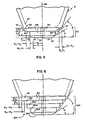
- Figure 4 is an enlarged fragmentary elevational view of the portion marked "IV" in Figure 3;
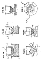
- Figures 5A to 5E are fragmentary elevational views, partly in section, illustrating the criticality of certain features of the invention;
- Figures 6 and 7 are views similar to that of Figure 4 but illustrating alternative embodiments of the inventio; and
- Figure 8 is an end view of a device of the invention, illustrating yet another embodiment.
- The invention is hereinafter described in connection with the preferred embodiments, in which the dispensing device is a disposable tip for mounting onto apparatus such as a manual or automated pipette, to dispense onto a dried test element serum which can be first aspirated into and contained in the tip. In addition, the invention is applicable to a dispensing device which is a permanent part of an aspirator or dispenser, or of a disposable blood separation device, or of a container wherein only the nozzle portion is disposable. The invention is useful regardless of the liquid being dispensed or the test element which receives it. It is further useful whether or not the device itself stores liquid prior to dispensing, or merely is fluidly connected to a separate device which provides such storage.
- The terms "up", "down", "bottom" and the like refer to orientations of parts during their preferred use, in an environment in which gravity is present. In addition, however, the invention is useful in an environment in which the "up" direction is arbitrary, such as a space station.
- The problems to which the invention is directed are illustrated in Figure 1. A
dispensing container 10 is mounted on apipette device 12, and is inserted, as shown byarrow 14, into a gross supply of liquid L incontainer 16, see Figure 1A. When a partial vacuum is generated inpipette device 12, liquid such as blood sera is drawn into dispensingcontainer 10, as shwon byarrows 18. Thecontainer 10 anddevice 12 are then withdrawn, in the direction ofarrow 20 in Figure 1B, and liquid breaks off, leaving drops "d" behind on the exterior surface of thecontainer 10. Thecontainer 10 is then placed adjacent to a test element E, as shown in Figure 1C, and a partial pressure is generated to dispense a portion of the contained liquid, as indicated byarrow 22. If the surface of that test element is relatively non-wetting, and/or if drops "d" touch the liquid being dispensed, perfusion of the liquid up the outside wall ofcontainer 10 is likely to occur. This in turn leads to significant variations in the amount of liquid received by element E, compared to the intended amount, of e.g. 10µl. - One solution to this problem is described in US Patent Specification US-A-4347875, and is illustrated for comparison in Figures 2A and 2B. In this dispensing device or
container 10, aliquid storage compartment 24 is provided with anozzle portion 26 comprising awall member 28 having abottom surface 30. Dispensingaperture 32 is formed in that surface.Nozzle portion 26 also includes anexterior surface 34 which has means at predetermined loci spaced (preferably at a distance "h" from surface 30) for attracting excess liquid onsurface 34 away fromsurface 30. Most preferably, such attracting means is theportion 40 ofsurface 34 which is angled at an angle α to the vertical as shown, to form a conical surface. Distance "h" is preferably a value of from about 0.02cm to about 0.5cm.Upper portion 44 is optionally ribbed to allow easier handling of the container. - In accordance with the present invention,
container 10 is improved in that it is provided with anew nozzle configuration 50, as shown in Figure 3 and more clearly in Figure 4. As before,container 10 includes aliquid storage compartment 24 which can acquire by aspiration as much as 400µl of liquid for dispensing.Nozzle portion 50 has been modified, however, to reflect certain liquid flow properties described hereinafter. As to its structure,nozzle 50 is formed from awall 52 which is wrapped around apassageway 54 which fluidly connectsorifice 32 withcompartment 24. Most preferably,container 10 and especiallynozzle 50 has an axis ofsymmetry 56 which is centered inpassageway 54 andaperture 32. - As before,
nozzle 50 includes abottom surface 30 extending a distance, preferably a radius R₁, fromaxis 56. Preferablysurface 30 is an annulus. Useful values of R₁ are set forth hereinafter. However, unlike the design shown in Figure 2,surface 30 is joined directly atedge 60, with asurface 62 inclined at an angle α to surface 30, the sign of angle α being such as to causesurfaces Surface 62 is generally annular and extends to subtend a distance, preferably a value which is the difference between radius R₂ and R₁, measured fromaxis 56. As used herein "generally annular" is satisfied if the shape approximates an annulus. In addition,nozzle 50 features a series oflands axis 56, up the side of the nozzle. Each of these lands is preferably generally annular in shape and generally parallel to surface 30 and has a dimension, preferably a radius R₃ and R₄, respectively, measured fromaxis 56, so that the surface area of each land is a function of the difference in the two bounding radii, RN-RN-1, where N is 3 forland 64, and N is 4 forland 66. Each land is stepped back, preferably straight back, so as to be spaced alongaxis 56 by a distance of h₂ and h₃ respectively, from the adjacent surface closer to surface 30. (Distance h₁ forsurface 62 is, of course, predetermined by the value of angle α and radius R₂.) - An important feature of
lands nozzle 50, an overall angle β, measured from the plane ofsurface 30, which is effective to give maximum drainage of liquid on the exterior ofnozzle 50, as described hereinafter. Other important features are the recesses formed by the step in each land, and distances h₂ and h₃. Each step forms a gap in the overall cone shape suggested by angle β, with a step-back surface 68 providing distance h₂ and h₃, such gaps being effective to trap and break up sheaths of liquid left on the exterior ofnozzle 50 during withdrawal of the container from the gross liquid supply. - It will be recognized that the shape of
lands back surface 68. Although eight-sided rings are shown, the number and even existence of "sides" is not critical. - The following Table gives a list of preferred ranges, and of an exemplary "most preferred" value, for each of the aforementioned dimensions.
Dimensional Values Items Range Most Preferred Angle α 6°-30° 12° Angle β 40°-60° 53° radius R₁ 0.057-0.076cm 0.063cm radius difference (R₂-R₁) 0.013-0.13cm 0.063cm radius difference (R₃-R₂) 0.013-0.13cm 0.076cm radius difference (R₄-R₃) 0.013-0.13cm 0.076cm height h₂* 0.035-0.08cm 0.05cm height h₃* 0.02-0.05cm 0.04cm *The reason for these being different from each other is explained hereinafter. - Most preferably, each of the
edges 70 created by the intersection of a surface such asland surface 62, with the vertically-extending step-back surface 68, is relatively sharp, that is, has a radius of curvature not to exceed about 0.02cm. - The significance of each of the topological features of
nozzle 50 will now be described, with reference to Figures 5A to 5D. - Angle β is selected because of the manner in which liquid drains from
nozzle 50 ascontainer 10 is withdrawn, as shown byarrow 20 in Figure 5A. High-speed studies have shown that the first events in the withdrawal tend to leave a sheath of liquid "S", which forms an angle to the remaining liquid L that is in fact a value of about 53°, or angle β if β is 53°. Thus, the best value for β is a value that mimicks this angle, although variances of -13° to +7° will also work, though less efficiently. - Angle α is selected because of the next event in the withdrawal of
nozzle 50 from liquid L, as shown in Figure 5B. At themoment nozzle 50 and its residual liquid are ready to break free of liquid L incontainer 16, the residual liquid onsurface 30 of the nozzle forms with liquid L, a "wiping angle" that is about 6 to 30°, usually about 12°. Thus, the cleanest construction to encourage the liquid "L" to wipe cleanly off ofsurface 62, and the preferred construction, is one in which surface 62 is inclined at that same angle. Although other values are not as efficient, angle α can be varied as shown in the Table. - It will also be apparent from Figures 5B and 5C the function performed by the
steps lands back surface 68 producing the land. Thus, accurate dispensing can take place with essentially no unacceptable change in the intended volume. - Figure 5D illustrates the reason for h₂ and h₃ having different values. As shown in this Figure, the 10µl drop D′ to be dispensed hangs from
surface 30 just prior to wetting the test element E. If this drop readily wets the surface of element E, then the liquid will alsowet surface 62 and move to position D˝ onnozzle 50, while dispensing into the element. The area wetted on element E is area A. If however the surface is relatively non-wetting then additional liquid volume is added to the initial drop D˝ to produce a drop DIIIof 10µl volume (since element E is slow to wet), as shown in Figure 5E, which proceeds to bulge out first to the solid line position and then to the dotted line position. When angle γ reaches and exceeds about 90°, the liquid jumps beyondsurface 62 and ontoland 64, as shown by the dashed line, DIV. The surface area ofland 64, taken with the areas ofsurfaces land 66 is a different story. Its separation distance h₃ is selected to be large enough so that the volume that can be supported fromsurfaces land 64 ontoland 66. The wetted area A of element E remains relatively constant, as shown in Figures 5D and 5E. h₃ is preferably no smaller than the 0.02cm minimum stated in the Table above, for the reason that the step created atland 66 for a given angle of β becomes too small to ensure that sheath S (Figure 5A) is effectively broken up into isolated 3-dimensional fillets of liquid extending around the steps' perimeter (Figure 5C). - Additional lands can be added further "up" the nozzle towards the storage compartment, as shown in Figure 6. Parts similar to those previously described bear the same reference numeral to which the distinguishing suffix "A" has been appended.
- Thus, referring to Figure 6, container 10A has a
nozzle 50A constructed substantially as before, with abottom surface 30A,annular ring surface 62A, and steps 64A and 66A. In addition, however, twoother steps back wall 82 to give a separation distance h₄ and h₅. Most preferably, eachstep - To establish the superior nature of this dispensing container, compared to the container described in the prior art with reference to Figure 2, ten containers constructed in accordance with Figure 2 and Figure 6 were tested, each with 300µl of DadeTM Moni-TrolTM ES level II control serum. They were each mounted on the same automated pipette which was programmed to dispense 10µl drops. For each container, nine drops were dispensed, after the liquid was first aspirated in using the process of Figures 1A and 1B shown above. The volumes so dispensed were measured, along with the mean values and the standard deviations. The following are the results:
Drop # Figure 2 Device Figure 6 Device mean volume standard deviation mean volume standard deviation 1st Drop 9.766 0.699 11.064* 0.184 2nd Drop 9.259 0.368 9.993 0.147 3rd Drop 9.912 1.136 10.009 0.085 4th Drop 9.656 0.229 10.044 0.112 5th Drop 9.919 0.113 9.987 0.063 6th Drop 10.237 0.045 9.948 0.058 7th Drop 10.583 0.166 9.938 0.092 8th Drop 10.501 0.216 9.976 0.059 9th Drop 10.268 0.146 9.976 0.117 *An artifact due to software optimized to work with the Figure 2 device. - For the Figure 2 device, this gives a three σ (sigma) total (three standard deviations) of 0.48 within-drop variation, and 0.37 as a drop-to-drop variation. For the Figure 6 device, if the first drop is ignored for the artifact that it is (due to software optimized to the Figure 2 configuration only), then the 3σ (sigma) variations for within-drop is only 0.11 and for drop-to-drop is only 0.033.
- It is not essential that each land be formed by a step-
back surface 68 which is always parallel to the container axis. Instead, such step-back surfaces can be inclined to the axis, as shown in Figure 7, to form an acute angle φ between the lands and the step-back surface. Parts similar to those previously described have the same reference numeral, to which the distinguishing suffix "b" has been appended. Thus, container 10b has anozzle 50b in which surfaces 30b and 62b are as before. However, lands 64b and 66b are spaced back by step-back walls 100 which are inclined by acute angle φ toaxis 56b. The overall effect on angles α and β is, however, nil. Angle φ can have values of from 75° to about 120°. - As in the case of the device of Figure 2, the containers of this invention can be manufactured from any material, most preferably synthetic polymers.
Claims (10)
a compartment (24) capable of holding liquid,
a passageway (54) extending from the compartment (24) and terminating in an aperture (32), and
a nozzle portion (50; 50A; 50b) fluidly connected to the passageway (54) and terminating in a liquid-spreading first exterior surface (30; 30A; 30b) disposed around the aperture (32), the nozzle portion (50; 50A; 50b) including a second exterior surface (62; 62A; 62b) extending from the first exterior surface (30; 30A; 30b);
characterized in that the second surface comprises an inclined surface (62; 62A; 62b) extending directly from the first surface (30; 30A; 30b) at a first angle (α) effective to force liquid on the exterior surfaces (30, 62; 30A, 62A; 30b, 62b) to detach from a source of liquid only when liquid has retreated from the inclined surface (62; 62A; 62b) to the first surface (30; 30A; 30b).
a compartment (24) having a storage capacity for the total liquid to be aspirated,
a nozzle (50A) in fluid communication with the compartment (24) and comprising a liquid-confining wall wrapped around an axis (56A) of symmetry and terminating in a liquid-spreading first exterior surface (30A), the first surface (30A) having an aperture (32) therein fluidly communicating with the compartment (24), the wall having a second exterior surface (62A) extending from the first exterior surface (30A) up the side of the nozzle (50A), configured to force liquid on the second surface (62A) to not interact with liquid dispensed through the aperture (32);
characterized in that the second surface comprises:
an annular surface (62A) extending directly from the first surface (30A) at an angle of about 12°, measured from the first exterior surface extended (30A),
and a series of four stepped lands (64A, 66A, 80, 81) of increasing outer dimensions, spaced up the side of the nozzle (50A) to form an overall angle of about 53°, measured from the first exterior surface (30A) extended, each of the lands (64A, 66A, 80, 81) having an annular surface which is generally parallel to the first surface (30A) with a radial extension dimension (RN - RN-1) which is between about 0.013cm and about 0.13cm, the one (64A) of the lands closest to the first exterior surface (30A) being spaced from the first annular surface (30A) along the axis a distance of about 0.05cm, and the remaining (66A, 80, 81) of the stepped lands being spaced along the axis (56) from the adjacent land closer to the first exterior surface (30A) a distance of about 0.04cm.
Applications Claiming Priority (2)
| Application Number | Priority Date | Filing Date | Title |
|---|---|---|---|
| US07/310,151 US4971763A (en) | 1989-02-14 | 1989-02-14 | Liquid-controlling nozzle geometry for dispensers of liquids |
| US310151 | 1989-02-14 |
Publications (3)
| Publication Number | Publication Date |
|---|---|
| EP0383563A2 true EP0383563A2 (en) | 1990-08-22 |
| EP0383563A3 EP0383563A3 (en) | 1991-04-17 |
| EP0383563B1 EP0383563B1 (en) | 1994-04-20 |
Family
ID=23201214
Family Applications (1)
| Application Number | Title | Priority Date | Filing Date |
|---|---|---|---|
| EP90301552A Expired - Lifetime EP0383563B1 (en) | 1989-02-14 | 1990-02-14 | Nozzle geometry for the control of liquid dispensing |
Country Status (8)
| Country | Link |
|---|---|
| US (1) | US4971763A (en) |
| EP (1) | EP0383563B1 (en) |
| JP (1) | JP2536946B2 (en) |
| KR (1) | KR900012685A (en) |
| CA (1) | CA1332727C (en) |
| DE (1) | DE69008216T2 (en) |
| HK (1) | HK129294A (en) |
| IE (1) | IE900528L (en) |
Cited By (5)
| Publication number | Priority date | Publication date | Assignee | Title |
|---|---|---|---|---|
| EP0508531A3 (en) * | 1991-04-10 | 1993-01-13 | Eastman Kodak Company | Liquid dispensing using container bottom sensing |
| EP0519390A3 (en) * | 1991-06-19 | 1993-02-24 | Eastman Kodak Company | Self-cleaning pipette tips |
| EP1254702A3 (en) * | 2001-04-23 | 2003-11-26 | Bioneer Corporation | Spotting device for fabricating microarrays of biological samples and spotting pin inserted therein |
| EP2091649A4 (en) * | 2006-11-16 | 2011-06-29 | Idexx Lab Inc | Pipette tip |
| EP1526918B1 (en) * | 2002-07-26 | 2014-06-25 | Ortho-Clinical Diagnostics, Inc. | Metering tip with internal features to control fluid meniscus and fluid oscillation |
Families Citing this family (20)
| Publication number | Priority date | Publication date | Assignee | Title |
|---|---|---|---|---|
| JP3420824B2 (en) * | 1994-04-15 | 2003-06-30 | 富士写真フイルム株式会社 | Method and apparatus for spotting sample liquid on dry analytical film piece |
| US5494828A (en) * | 1994-07-13 | 1996-02-27 | Leopando; Mark E. | Slide dispensing device and method |
| US5811306A (en) * | 1995-09-04 | 1998-09-22 | Fuji Photo Film Co., Ltd. | Liquid spotting method |
| IL121968A0 (en) * | 1997-10-14 | 1998-03-10 | A R T Medical Instr Ltd | Method for depositing a microvolume of liquid on a surface and apparatus therefor and a microvolume pump therefor |
| US6551557B1 (en) * | 1998-07-07 | 2003-04-22 | Cartesian Technologies, Inc. | Tip design and random access array for microfluidic transfer |
| US6475440B1 (en) * | 1998-09-16 | 2002-11-05 | Clontech Laboratories, Inc. | Applicator for use in deposition of fluid samples onto a substrate surface |
| GB9824202D0 (en) * | 1998-11-04 | 1998-12-30 | Moore David F | Liquid transfer system |
| US6610253B2 (en) * | 2000-05-31 | 2003-08-26 | Autosplice, Inc. | Liquid pin transfer assembly with common pin bias |
| US6579499B1 (en) * | 2000-05-31 | 2003-06-17 | Autosplice, Inc. | Liquid compound pin replicator with weight bias |
| US6796704B1 (en) * | 2000-06-06 | 2004-09-28 | W. Gerald Lott | Apparatus and method for mixing components with a venturi arrangement |
| AU2002952248A0 (en) * | 2002-10-25 | 2002-11-07 | Goodcart Pty Ltd | Multi purpose pole |
| US7185551B2 (en) * | 2003-05-22 | 2007-03-06 | Schwartz H Donald | Pipetting module |
| JP2005069830A (en) * | 2003-08-22 | 2005-03-17 | Sysmex Corp | Dispensation chip and analyzer using it |
| US7396512B2 (en) | 2003-11-04 | 2008-07-08 | Drummond Scientific Company | Automatic precision non-contact open-loop fluid dispensing |
| US7279135B2 (en) * | 2004-05-10 | 2007-10-09 | Taiwan Micro System Co., Ltd. | Probe for providing micro liquid drops |
| JP4964547B2 (en) * | 2006-09-21 | 2012-07-04 | 株式会社サカエ | Automatic analyzer |
| EP2409676A1 (en) * | 2010-07-06 | 2012-01-25 | Intervet International B.V. | Method for dosing a fluid formulation containing a medicinal substance |
| WO2015198469A1 (en) * | 2014-06-27 | 2015-12-30 | 株式会社 エー・アンド・デイ | Pipette tip |
| EP3379256B1 (en) | 2015-11-16 | 2025-04-16 | Otsuka Pharmaceutical Co., Ltd. | Test kit, liquid delivery method and testing apparatus using test kit |
| CN110292962B (en) * | 2019-07-12 | 2023-04-07 | 圣湘生物科技股份有限公司 | Liquid suction control method, device, equipment, system and storage medium |
Family Cites Families (5)
| Publication number | Priority date | Publication date | Assignee | Title |
|---|---|---|---|---|
| US3449081A (en) * | 1965-03-29 | 1969-06-10 | Electronic Instr Co | Test kit |
| US4041995A (en) * | 1975-01-30 | 1977-08-16 | Eastman Kodak Company | Gas pressure-activated drop dispenser |
| US4237095A (en) * | 1978-04-25 | 1980-12-02 | Kommandiittiyhtio Finnpipette Osmo A. Suovaniemi | Tip vessel for use in connection with a dosage pipette |
| US4347875A (en) * | 1980-07-14 | 1982-09-07 | Eastman Kodak Company | Self-cleaning nozzle construction for aspirators |
| EP0082263A1 (en) * | 1981-12-10 | 1983-06-29 | The Perkin-Elmer Corporation | Sample introduction for chemical analysis by spectrometry/liquid chromatography |
-
1989
- 1989-02-14 US US07/310,151 patent/US4971763A/en not_active Expired - Lifetime
- 1989-09-11 CA CA000610866A patent/CA1332727C/en not_active Expired - Fee Related
-
1990
- 1990-02-14 JP JP2031648A patent/JP2536946B2/en not_active Expired - Fee Related
- 1990-02-14 KR KR1019900001807A patent/KR900012685A/en not_active Withdrawn
- 1990-02-14 DE DE69008216T patent/DE69008216T2/en not_active Expired - Fee Related
- 1990-02-14 IE IE900528A patent/IE900528L/en unknown
- 1990-02-14 EP EP90301552A patent/EP0383563B1/en not_active Expired - Lifetime
-
1994
- 1994-11-17 HK HK129294A patent/HK129294A/en not_active IP Right Cessation
Cited By (6)
| Publication number | Priority date | Publication date | Assignee | Title |
|---|---|---|---|---|
| EP0508531A3 (en) * | 1991-04-10 | 1993-01-13 | Eastman Kodak Company | Liquid dispensing using container bottom sensing |
| EP0519390A3 (en) * | 1991-06-19 | 1993-02-24 | Eastman Kodak Company | Self-cleaning pipette tips |
| EP1254702A3 (en) * | 2001-04-23 | 2003-11-26 | Bioneer Corporation | Spotting device for fabricating microarrays of biological samples and spotting pin inserted therein |
| EP1526918B1 (en) * | 2002-07-26 | 2014-06-25 | Ortho-Clinical Diagnostics, Inc. | Metering tip with internal features to control fluid meniscus and fluid oscillation |
| EP2091649A4 (en) * | 2006-11-16 | 2011-06-29 | Idexx Lab Inc | Pipette tip |
| AU2007322064B2 (en) * | 2006-11-16 | 2013-07-25 | Idexx Laboratories, Inc. | Pipette tip |
Also Published As
| Publication number | Publication date |
|---|---|
| DE69008216D1 (en) | 1994-05-26 |
| EP0383563A3 (en) | 1991-04-17 |
| KR900012685A (en) | 1990-09-01 |
| JP2536946B2 (en) | 1996-09-25 |
| DE69008216T2 (en) | 1994-08-04 |
| JPH02290560A (en) | 1990-11-30 |
| HK129294A (en) | 1994-11-25 |
| US4971763A (en) | 1990-11-20 |
| IE900528L (en) | 1990-08-14 |
| EP0383563B1 (en) | 1994-04-20 |
| CA1332727C (en) | 1994-10-25 |
Similar Documents
| Publication | Publication Date | Title |
|---|---|---|
| EP0383563B1 (en) | Nozzle geometry for the control of liquid dispensing | |
| US4347875A (en) | Self-cleaning nozzle construction for aspirators | |
| US7300525B2 (en) | Device for cleaning pipette probes or stirrers | |
| US5537880A (en) | Automatic pipetting apparatus with leak detection and method of detecting a leak | |
| EP0607442B1 (en) | Method of diluting highly viscous liquid | |
| EP0140247A2 (en) | Multiple trough vessel for automated liquid handling apparatus | |
| US4615360A (en) | Means providing separation of exterior sheath of liquid on dispensing tip | |
| CN108325439B (en) | Method and apparatus for mitigating bubble formation in a liquid | |
| US5279794A (en) | Probe washing unit and automatic analysis system having probe washing unit | |
| WO1993024232A1 (en) | Calibrated pipette tip and method | |
| WO1995006867A1 (en) | Improved method and apparatus for aliquotting blood serum or blood plasma | |
| CN102326085B (en) | Chemical Analysis Device | |
| CA2493611C (en) | Metering tip with internal features to control fluid meniscus and fluid oscillation | |
| WO1987005533A1 (en) | Modular reservoir system | |
| US4936152A (en) | Pipette tip storage tray and method of use | |
| US4567021A (en) | U-Shaped reaction tube made of elastic material | |
| US5322192A (en) | Pipetting apparatus | |
| MX2007000704A (en) | Method and apparatus for forming a dilution by fluid dispersion. | |
| JPH07333230A (en) | Liquid dispensing device and automatic analyzer using the same | |
| JP3389352B2 (en) | Liquid dispensing device | |
| JP3149295B2 (en) | Two-liquid stirring method using a nozzle tip | |
| JPH06317599A (en) | Dispenser | |
| EP0078109A1 (en) | Liquid dispenser | |
| JP2021128152A (en) | Maintenance reservoir | |
| JPH1062436A (en) | Liquid dispensing method and device |
Legal Events
| Date | Code | Title | Description |
|---|---|---|---|
| PUAI | Public reference made under article 153(3) epc to a published international application that has entered the european phase |
Free format text: ORIGINAL CODE: 0009012 |
|
| AK | Designated contracting states |
Kind code of ref document: A2 Designated state(s): BE CH DE FR GB IT LI LU NL |
|
| PUAL | Search report despatched |
Free format text: ORIGINAL CODE: 0009013 |
|
| AK | Designated contracting states |
Kind code of ref document: A3 Designated state(s): BE CH DE FR GB IT LI LU NL |
|
| 17P | Request for examination filed |
Effective date: 19910912 |
|
| 17Q | First examination report despatched |
Effective date: 19921123 |
|
| GRAA | (expected) grant |
Free format text: ORIGINAL CODE: 0009210 |
|
| AK | Designated contracting states |
Kind code of ref document: B1 Designated state(s): BE CH DE FR GB IT LI LU NL |
|
| PG25 | Lapsed in a contracting state [announced via postgrant information from national office to epo] |
Ref country code: IT Free format text: LAPSE BECAUSE OF FAILURE TO SUBMIT A TRANSLATION OF THE DESCRIPTION OR TO PAY THE FEE WITHIN THE PRESCRIBED TIME-LIMIT;WARNING: LAPSES OF ITALIAN PATENTS WITH EFFECTIVE DATE BEFORE 2007 MAY HAVE OCCURRED AT ANY TIME BEFORE 2007. THE CORRECT EFFECTIVE DATE MAY BE DIFFERENT FROM THE ONE RECORDED. Effective date: 19940420 Ref country code: NL Effective date: 19940420 Ref country code: FR Effective date: 19940420 Ref country code: BE Effective date: 19940420 |
|
| REF | Corresponds to: |
Ref document number: 69008216 Country of ref document: DE Date of ref document: 19940526 |
|
| EN | Fr: translation not filed | ||
| NLV1 | Nl: lapsed or annulled due to failure to fulfill the requirements of art. 29p and 29m of the patents act | ||
| PLBE | No opposition filed within time limit |
Free format text: ORIGINAL CODE: 0009261 |
|
| PG25 | Lapsed in a contracting state [announced via postgrant information from national office to epo] |
Ref country code: LU Free format text: LAPSE BECAUSE OF NON-PAYMENT OF DUE FEES Effective date: 19950228 |
|
| 26N | No opposition filed | ||
| REG | Reference to a national code |
Ref country code: GB Ref legal event code: 732E |
|
| REG | Reference to a national code |
Ref country code: GB Ref legal event code: IF02 |
|
| PGFP | Annual fee paid to national office [announced via postgrant information from national office to epo] |
Ref country code: DE Payment date: 20070208 Year of fee payment: 18 |
|
| PGFP | Annual fee paid to national office [announced via postgrant information from national office to epo] |
Ref country code: CH Payment date: 20070214 Year of fee payment: 18 Ref country code: GB Payment date: 20070214 Year of fee payment: 18 |
|
| REG | Reference to a national code |
Ref country code: CH Ref legal event code: PL |
|
| GBPC | Gb: european patent ceased through non-payment of renewal fee |
Effective date: 20080214 |
|
| PG25 | Lapsed in a contracting state [announced via postgrant information from national office to epo] |
Ref country code: CH Free format text: LAPSE BECAUSE OF NON-PAYMENT OF DUE FEES Effective date: 20080229 Ref country code: LI Free format text: LAPSE BECAUSE OF NON-PAYMENT OF DUE FEES Effective date: 20080229 |
|
| PG25 | Lapsed in a contracting state [announced via postgrant information from national office to epo] |
Ref country code: DE Free format text: LAPSE BECAUSE OF NON-PAYMENT OF DUE FEES Effective date: 20080902 |
|
| PG25 | Lapsed in a contracting state [announced via postgrant information from national office to epo] |
Ref country code: GB Free format text: LAPSE BECAUSE OF NON-PAYMENT OF DUE FEES Effective date: 20080214 |