EP2091180A1 - Method, system and device for realizing switching between main and spare - Google Patents
Method, system and device for realizing switching between main and spare Download PDFInfo
- Publication number
- EP2091180A1 EP2091180A1 EP08835192A EP08835192A EP2091180A1 EP 2091180 A1 EP2091180 A1 EP 2091180A1 EP 08835192 A EP08835192 A EP 08835192A EP 08835192 A EP08835192 A EP 08835192A EP 2091180 A1 EP2091180 A1 EP 2091180A1
- Authority
- EP
- European Patent Office
- Prior art keywords
- standby
- active
- address
- communication
- physical
- Prior art date
- Legal status (The legal status is an assumption and is not a legal conclusion. Google has not performed a legal analysis and makes no representation as to the accuracy of the status listed.)
- Withdrawn
Links
Images


Classifications
-
- H—ELECTRICITY
- H04—ELECTRIC COMMUNICATION TECHNIQUE
- H04L—TRANSMISSION OF DIGITAL INFORMATION, e.g. TELEGRAPHIC COMMUNICATION
- H04L45/00—Routing or path finding of packets in data switching networks
-
- H—ELECTRICITY
- H04—ELECTRIC COMMUNICATION TECHNIQUE
- H04L—TRANSMISSION OF DIGITAL INFORMATION, e.g. TELEGRAPHIC COMMUNICATION
- H04L45/00—Routing or path finding of packets in data switching networks
- H04L45/02—Topology update or discovery
-
- H—ELECTRICITY
- H04—ELECTRIC COMMUNICATION TECHNIQUE
- H04L—TRANSMISSION OF DIGITAL INFORMATION, e.g. TELEGRAPHIC COMMUNICATION
- H04L45/00—Routing or path finding of packets in data switching networks
- H04L45/22—Alternate routing
-
- H—ELECTRICITY
- H04—ELECTRIC COMMUNICATION TECHNIQUE
- H04L—TRANSMISSION OF DIGITAL INFORMATION, e.g. TELEGRAPHIC COMMUNICATION
- H04L45/00—Routing or path finding of packets in data switching networks
- H04L45/28—Routing or path finding of packets in data switching networks using route fault recovery
-
- H—ELECTRICITY
- H04—ELECTRIC COMMUNICATION TECHNIQUE
- H04L—TRANSMISSION OF DIGITAL INFORMATION, e.g. TELEGRAPHIC COMMUNICATION
- H04L45/00—Routing or path finding of packets in data switching networks
- H04L45/56—Routing software
- H04L45/566—Routing instructions carried by the data packet, e.g. active networks
Definitions
- the present invention relates to a mobile communication technology, and in particular, to a method, system, and device for implementing active/standby switchover.
- the active/standby switchover technology is adopted to ensure the reliability of a communication system. That is, two devices (namely, an active device and a standby device) are configured. Normally, the active device provides services for the system. When the active device is faulty, the system switches over to the standby device, so that the standby device provides services for the system.
- the active/standby switchover is a relative concept. During actual applications, two devices are backed up mutually.
- the active and standby devices share the same floating IP address, which means that a specific IP address is bound to a device that is working, such as a network adapter on the active device; when the active device is faulty, the floating IP address occupied by the active device is released and bound to a network adapter on the standby device.
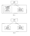
- FIG. 1-FIG 3 show a conventional active/standby switchover solution adopting the floating IP technology.
- active device A occupies the floating IP address, and the data sent to the floating IP address by an application device (APP) is sent to active device A.
- APP application device
- FIG. 2 active device A releases the floating IP address. In this case, the system is in the offline state and cannot work normally.
- standby device B occupies the floating IP address.
- the inventor finds at least the following defects in the conventional technology.
- the foregoing method can be used to implement the active/standby switchover, but the physical environment setting needs to be modified while the active device releases the floating IP address and the standby device occupies the floating IP address. As a result, the currently ongoing services are interrupted. In addition, modifying the physical environment setting takes a long time generally. With regard to a real-time communication system, it is unacceptable that the normal running of services is affected for a long time.
- Embodiments of the present invention provide a method for implementing the active/standby switchover to prevent the ongoing services from a long interruption when the active/standby switchover is performed.
- Embodiments of the present invention provide a system for implementing the active/standby switchover to prevent the ongoing services from a long interruption when the active/standby switchover is performed.
- Embodiments of the present invention provide a device for implementing the active/standby switchover to prevent the ongoing services from a long interruption when the active/standby switchover is performed.
- a method for implementing an active/standby switchover includes:
- a system for implementing an active/standby switchover includes a standby device, an application device (APP), and a communication unit, where:
- the APP is adapted to send data to the communication unit
- the communication unit is adapted to send the received data from the APP to the standby device corresponding to a physical IP address in a mapping relation with a preset communication ID;
- the standby device is adapted to receive the data from the communication unit.
- a device for implementing an active/standby switchover includes a receiving unit and a sending unit, where:
- the receiving unit is adapted to receive data sent to a standby device corresponding to a physical IP address in a mapping relation with a preset communication ID when the system performs the active/standby switchover;
- the sending unit is adapted to send the received data to the standby device.
- the system automatically obtains a target device to which data is to be sent and sends data to the target device according to a mapping relation between a preset communication ID and a physical IP address; the system sends the data that is sent to the communication ID to a device corresponding to the physical IP address that is currently mapped to the communication ID according to the mapping relation of the communication ID when performing the active/standby switchover.
- the solution of the present invention changes only the mapping relation between the communication ID and the physical IP address of a device when the active/standby switchover is performed. The setting of the physical environment does not need to be changed. Thus, a long interruption of ongoing services is prevented.
- FIG. 1-FIG. 3 show the conventional active/standby switchover solution that adopts the floating IP technology
- FIG. 4 shows a structure of a system for implementing an active/standby switchover in an embodiment of the present invention
- FIG. 5 shows a structure of a device for implementing an active/standby switchover in an embodiment of the present invention.
- FIG. 6 is a flowchart of a method for implementing an active/standby switchover in an embodiment of the present invention.
- embodiments of the present invention provide a new solution to the active/standby switchover. That is, when the system performs the active/standby switchover, it sends the received data to a standby device corresponding to the physical IP address in a mapping relation with the preset communication identification (ID).
- ID preset communication identification
- the specific implementation can be as follows: establishing a mapping relation between the preset communication ID and the physical IP address of an active device or the physical IP address of a standby device in advance; at a point of time during the communication, the communication ID in the mapping relation with the physical IP address of the active device or the physical IP address of the standby device is uniquely mapped to either the physical IP address of the active device or the physical IP address of the standby device. At this time, a mapping relation between the communication ID and the physical IP address of the active device or the physical IP address of the standby device is established. That is, the physical IP address of the active device and the physical IP address of the standby device are relatively stable.
- the subsequent process is as follows: receiving the data that is sent to the communication ID; sending the received data to a device corresponding to the physical IP address in the mapping relation with the communication ID; changing the physical IP address in the mapping relation with the communication ID to the physical IP address of a device for switchover and sending the data that is sent to the communication ID to the device corresponding to the new physical IP address when the system needs to perform the active/standby switchover.
- FIG. 4 shows a structure of a system for implementing an active/standby switchover in an embodiment of the present invention.
- the system includes a standby device 42, an APP 43, and a communication unit 44.
- the APP 43 is adapted to send data to the communication unit 44.
- the communication unit 44 is adapted to send the received data from the APP 43 to the standby device 42 corresponding to the physical IP address in a mapping relation with the preset communication ID.
- the standby device 42 is adapted to receive data from the communication unit 44.
- the system further includes an active device 41, which is adapted to receive data from the communication unit 44.
- the communication unit 44 is further adapted to send the received data to the active device 41 corresponding to the physical IP address in the mapping relation with the communication ID before the system performs the active/standby switchover, and change the physical IP address in the mapping relation with the communication ID when determining that the system needs to perform the active/standby switchover; that is, the object mapped to the communication ID is the physical IP address of the active device 41 before the active/standby switchover, and the object mapped to the communication ID is changed to the physical IP address of the standby device 42 after the active/standby switchover.
- the communication unit 44 stores the mapping relation between the preset communication ID and the physical IP address of the active device 41 and the physical IP address of the standby device 42 in advance; at a point of time during the communication, the communication ID is uniquely mapped to either the physical IP address of the active device 41 and the physical IP address of the standby device 42.
- the communication unit 44 is composed of three communication layers that correspond to the APP 43, the active device 41, and the standby device 42.
- the process of establishing a mapping relation between the communication ID and the physical IP address of the active device 41 and the physical IP address of the standby device 42 in advance can be performed at any of the three communication layers; after the mapping relation is established, the three communication layers maintain consistency of stored information automatically by exchanging information.
- the three communication layers store the mapping relation between the preset communication ID and the physical IP address of the active device 41 and the physical IP address of the standby device 42; when detecting that the active/standby switchover needs to be performed for a certain reason (for example, the active device is faulty), the system requests the communication unit 44 to modify the currently stored mapping relation by exchanging information with the communication unit 44 (that is, before the active/standby switchover, the object mapped to the communication ID is the physical IP address of the active device 41, and after the active/standby switchover, the object mapped to the communication ID is changed to the physical IP address of the standby device 42).
- a communication layer of the communication unit 44 shown in FIG. 4 changes the physical IP address of a device (such as the physical IP address of the active device 41) in the mapping relation with the communication ID to the physical IP address of the standby device 42; at the same time, the three communication layers update information to maintain consistency.
- one of the three communication layers may function as a processing center; all settings and changes are performed in the communication layer; and the communication layer notifies other communication layers of the changes in time, thus maintaining consistency of the information stored at each communication layer.
- FIG. 5 shows a structure of a device for implementing an active/standby switchover in an embodiment of the present invention.
- the device includes a receiving unit 51 and a sending unit 52.
- the receiving unit 51 is adapted to receive the data that is sent to the standby device 42 corresponding to the physical IP address in a mapping relation with the preset communication ID when the system performs the active/standby switchover.
- the sending unit 52 is adapted to send the received data to the standby device 42.
- the sending unit is further adapted to send the received data to the active device 41 corresponding to the physical IP address in the mapping relation with the communication ID before the system performs the active/standby switchover.
- the device further includes a modifying unit 53, which is adapted to change the physical IP address of the active device 41 in the mapping relation with the communication ID to the physical IP address of the standby device 42 for switchover when the system needs to perform the active/standby switchover.
- a modifying unit 53 which is adapted to change the physical IP address of the active device 41 in the mapping relation with the communication ID to the physical IP address of the standby device 42 for switchover when the system needs to perform the active/standby switchover.
- the device further includes an establishing unit 54, which is adapted to establish the mapping relation between the preset communication ID and the physical IP address of the active device 41 and the physical IP address of the standby device 42; at a point of time during the communication, the communication ID is uniquely mapped to either the physical IP address of the active device 41 and the physical IP address of the standby device 42.
- the sending unit 52 obtains a physical IP address currently mapped to the communication ID by querying the establishing unit 54, and then sends the data from the receiving unit 51 to a device corresponding to the obtained physical IP address.
- the device further includes a judging unit 55, which is adapted to judge whether a device that sends data to the receiving unit 51 is connected to a device that corresponds to the obtained physical IP address; if the two devices are connected to each other, notify the sending unit 52 of using the original connection to send data to the device that corresponds to the obtained physical IP address; if the two devices are not connected to each other, establish a connection between them and notify the sending unit 52 of using the new connection to send data to the device that corresponds to the obtained physical IP address.
- a judging unit 55 which is adapted to judge whether a device that sends data to the receiving unit 51 is connected to a device that corresponds to the obtained physical IP address; if the two devices are connected to each other, notify the sending unit 52 of using the original connection to send data to the device that corresponds to the obtained physical IP address; if the two devices are not connected to each other, establish a connection between them and notify the sending unit 52 of using the new connection to send data to the device that corresponds to the obtained physical IP address.
- FIG. 6 is a flowchart of a method for implementing an active/standby switchover in an embodiment of the present invention. This embodiment is implemented according to the system shown in FIG. 4 ; as shown in FIG. 6 , the implementation process includes the following steps:
- Step S601 Set a communication ID.
- one or more communication IDs are set at a communication layer.
- Each communication ID corresponds to only one actual physical IP address at a point of time, but different communication IDs can correspond to the same physical IP address.
- a set communication ID can be represented by a number, such as 1, 2, ..., and N (N indicates the quantity of communication IDs).
- a set communication ID corresponds to a group of active devices and standby devices. The step of sending data to an active device can be regarded as sending data to the communication ID.
- Embodiments of the present invention use only one communication ID. Therefore, the case of multiple communication IDs is unrelated to the embodiment. For ease of description, assume that only one communication ID is set in the embodiment.
- Step S602 Establish a mapping relation between the communication ID and the physical IP address of an active device or the physical IP address of a standby device.
- the mapping relation between the communication ID and the physical IP address of the active device and the physical IP address of the standby device is established at the communication layer, but at a point of time during the communication, the communication ID is uniquely mapped to either the physical IP address of the active device and the physical IP address of the standby device. If the currently mapped physical IP address is the physical IP address of the active device (IP1), the relation is as follows: ID->IP1. The method for establishing a mapping relation is included in the conventional technology and therefore not detailed herein.
- step S601 to step S602 can be performed at one of the three communication layers shown in FIG. 4 . Assume that step S60 and step S602 are performed in a communication layer that corresponds to an APP.
- Step S603 Receive the data that is sent to the communication ID and send the received data to a device corresponding to the physical IP address currently mapped to the communication ID.
- the APP at the service layer requests the corresponding communication layer to send data; the communication layer corresponding to the APP obtains the physical IP address (IP1) currently mapped to the communication ID according to the preset mapping relation of the communication ID; after obtaining the required physical IP address, the communication layer judges whether the APP is connected to an active device corresponding to IP1; if the APP is connected to the active device, the communication layer uses the established connection to send the data from the APP to the active device; if the APP is not connected to the active device, the communication layer establishes a connection between the APP and the active device, and then sends the data from the APP to the active device.
- IP1 physical IP address
- the method for judging whether the APP is connected to the active device may be querying for the records of the communication layer. If the APP is connected to the active device, the communication layer corresponding to the APP and the active device will save the corresponding communication ID as a record. Whether the APP is connected to the active device can be known by querying whether the corresponding record exists.
- Step S604 When the active/standby switchover needs to be performed, change the physical IP address of the active device in the mapping relation with the communication ID to the physical IP address of the standby device. That is, the object mapped to the communication ID is the physical IP address of the active device before the active/standby switchover, and the object mapped to the communication ID is changed to the physical IP address of the standby device after the active/standby switchover (after the active/standby switchover, the object mapped to the communication ID is changed).
- the system when detecting that the active/standby switchover needs to be performed (so that the standby device provides services for the system) for a certain reason (for example, the active device is faulty), the system changes the physical IP address of the active device in the mapping relation with the communication ID to the physical IP address of the standby device for switchover.
- IP1 currently mapped to the communication ID is changed to IP2.
- the corresponding formula is as follows: During the active/standby switchover, communication ID -> physical IP address (IP1) of the active device is changed to communication ID -> physical IP address (IP1) of the standby device.
- mapping relation at the communication layer is changed during the active/standby switchover in this step.
- the change of the physical environment is not required.
- Step S605 Receive the data that is sent to the communication ID and send the received data to a device corresponding to the new physical IP address in the mapping relation with the communication ID after the active/standby switchover is performed.
- the APP at the service layer requests the corresponding communication layer to send data; the communication layer corresponding to the APP obtains the physical IP address (IP2) currently mapped to the communication ID according to the changed mapping relation; after obtaining the required physical IP address, the communication layer judges whether the APP is connected to the standby device corresponding to IP2; if the APP is connected to the standby device, the communication layer uses the established connection to directly send the data from the APP to the standby device; if the APP is not connected to the standby device, the communication layer establishes a connection between the APP and the standby device, and then sends the data from the APP to the standby device.
- IP2 physical IP address
- the service layer is separated from the communication layer.
- a device at the service layer such as an APP, needs to know only the target communication ID to which data is to be sent and sends data to the communication ID without knowing the specific communication protocol.
- the communication layer automatically obtains the target device to which data is to be sent and sends data to the target device according to the mapping relation between the preset communication ID and the physical IP address.
- the communication layer only needs to change the physical IP address of the active device in the mapping relation with the communication ID to the physical IP address of the standby device for switchover. According to the changed mapping relation, the communication layer sends the data that is sent to the communication ID to the device corresponding to the new physical IP address.
- the solution of the present invention changes only the mapping relation between the communication ID and the physical IP address of a device when the active/standby switchover is performed.
- the setting of the physical environment does not need to be changed. Thus, a long interruption of ongoing services is prevented, and development of real-time services is facilitated.
- the embodiments of the present invention may be implemented through software and a necessary general hardware platform or through hardware only. However, in most cases, software and a general hardware platform are preferred. Based on such understanding, the technical solution of the present invention or contributions to the conventional technology may be embodied by a software product.
- the software product is stored in a storage medium and incorporates several instructions to instruct a computer device, for example, a personal computer, a server, or a network device, to execute the method provided by each embodiment of the present invention.
Landscapes
- Engineering & Computer Science (AREA)
- Computer Networks & Wireless Communication (AREA)
- Signal Processing (AREA)
- Data Exchanges In Wide-Area Networks (AREA)
Applications Claiming Priority (2)
| Application Number | Priority Date | Filing Date | Title |
|---|---|---|---|
| CNA2007101518677A CN101150439A (zh) | 2007-09-25 | 2007-09-25 | 一种实现主备切换的方法、系统及设备 |
| PCT/CN2008/072494 WO2009043281A1 (fr) | 2007-09-25 | 2008-09-24 | Procédé, système et dispositif pour réaliser une commutation entre principal et de rechange |
Publications (1)
| Publication Number | Publication Date |
|---|---|
| EP2091180A1 true EP2091180A1 (en) | 2009-08-19 |
Family
ID=39250791
Family Applications (1)
| Application Number | Title | Priority Date | Filing Date |
|---|---|---|---|
| EP08835192A Withdrawn EP2091180A1 (en) | 2007-09-25 | 2008-09-24 | Method, system and device for realizing switching between main and spare |
Country Status (4)
| Country | Link |
|---|---|
| US (1) | US20100098085A1 (zh) |
| EP (1) | EP2091180A1 (zh) |
| CN (1) | CN101150439A (zh) |
| WO (1) | WO2009043281A1 (zh) |
Cited By (1)
| Publication number | Priority date | Publication date | Assignee | Title |
|---|---|---|---|---|
| EP2523480A4 (en) * | 2010-04-02 | 2017-06-21 | ZTE Corporation | Method and system for emergency switching |
Families Citing this family (20)
| Publication number | Priority date | Publication date | Assignee | Title |
|---|---|---|---|---|
| CN101150439A (zh) * | 2007-09-25 | 2008-03-26 | 华为技术有限公司 | 一种实现主备切换的方法、系统及设备 |
| EP3373547B1 (en) * | 2011-05-31 | 2020-09-16 | Huawei Technologies Co., Ltd. | Method for realizing disaster tolerance backup |
| CN102739453B (zh) * | 2012-07-03 | 2015-07-29 | 华为软件技术有限公司 | 主备切换方法、设备及系统 |
| CN105451222B (zh) * | 2014-07-31 | 2019-10-22 | 华为技术有限公司 | 一种终端建立连接的方法、装置及系统 |
| CN104317208B (zh) * | 2014-10-17 | 2017-08-25 | 安徽立卓智能电网科技有限公司 | 一种用户机自动识别指挥机主备切换的方法 |
| CN104679604A (zh) * | 2015-02-12 | 2015-06-03 | 大唐移动通信设备有限公司 | 一种主节点和备节点切换的方法和装置 |
| CN105138423A (zh) * | 2015-08-11 | 2015-12-09 | 北京思特奇信息技术股份有限公司 | 一种双机切换时业务大数据的恢复方法及系统 |
| CN105391574A (zh) * | 2015-10-28 | 2016-03-09 | 曙光云计算技术有限公司 | 一种服务器地址设置方法及装置 |
| CN105530120A (zh) * | 2015-12-01 | 2016-04-27 | 中国建设银行股份有限公司 | 一种业务处理方法、控制器及业务处理系统 |
| CN109120425A (zh) * | 2017-06-26 | 2019-01-01 | 中兴通讯股份有限公司 | 堆叠系统带外管理的方法、设备及计算机可读存储介质 |
| CN107508700B (zh) * | 2017-08-15 | 2021-01-15 | 北京小米移动软件有限公司 | 容灾方法、装置、设备及存储介质 |
| US10581730B2 (en) | 2018-07-12 | 2020-03-03 | Vmware, Inc. | Packet processing using service chains |
| US10645201B2 (en) * | 2018-07-31 | 2020-05-05 | Vmware, Inc. | Packet handling during service virtualized computing instance migration |
| CN110932876B (zh) * | 2018-09-19 | 2022-12-02 | 华为技术有限公司 | 一种通信系统、方法及装置 |
| WO2020199212A1 (zh) * | 2019-04-04 | 2020-10-08 | 华为技术有限公司 | 一种通信方法及装置 |
| CN111431963B (zh) * | 2020-02-20 | 2023-11-24 | 视联动力信息技术股份有限公司 | 一种响应呼叫的方法、系统及装置 |
| CN111447393B (zh) * | 2020-03-04 | 2023-08-18 | 视联动力信息技术股份有限公司 | 会议维护方法、装置及可读存储介质 |
| CN113301239A (zh) * | 2021-07-27 | 2021-08-24 | 康达洲际医疗器械有限公司 | 一种基于功能互享的成像系统群控制方法与系统 |
| US11595245B1 (en) * | 2022-03-27 | 2023-02-28 | Bank Of America Corporation | Computer network troubleshooting and diagnostics using metadata |
| US11863631B1 (en) * | 2023-02-23 | 2024-01-02 | Cisco Technology, Inc. | Secure access App Connectors |
Family Cites Families (4)
| Publication number | Priority date | Publication date | Assignee | Title |
|---|---|---|---|---|
| US6108300A (en) * | 1997-05-02 | 2000-08-22 | Cisco Technology, Inc | Method and apparatus for transparently providing a failover network device |
| US6768726B2 (en) * | 2002-08-06 | 2004-07-27 | Motorola, Inc. | Method and apparatus for effecting a seamless handoff between IP connections |
| CN100407619C (zh) * | 2003-11-18 | 2008-07-30 | 中兴通讯股份有限公司 | 使用网络处理器实现端口主备切换的方法 |
| CN101150439A (zh) * | 2007-09-25 | 2008-03-26 | 华为技术有限公司 | 一种实现主备切换的方法、系统及设备 |
-
2007
- 2007-09-25 CN CNA2007101518677A patent/CN101150439A/zh active Pending
-
2008
- 2008-09-24 WO PCT/CN2008/072494 patent/WO2009043281A1/zh active Application Filing
- 2008-09-24 EP EP08835192A patent/EP2091180A1/en not_active Withdrawn
-
2009
- 2009-12-21 US US12/643,583 patent/US20100098085A1/en not_active Abandoned
Non-Patent Citations (1)
| Title |
|---|
| See references of WO2009043281A1 * |
Cited By (1)
| Publication number | Priority date | Publication date | Assignee | Title |
|---|---|---|---|---|
| EP2523480A4 (en) * | 2010-04-02 | 2017-06-21 | ZTE Corporation | Method and system for emergency switching |
Also Published As
| Publication number | Publication date |
|---|---|
| CN101150439A (zh) | 2008-03-26 |
| WO2009043281A1 (fr) | 2009-04-09 |
| US20100098085A1 (en) | 2010-04-22 |
Similar Documents
| Publication | Publication Date | Title |
|---|---|---|
| EP2091180A1 (en) | Method, system and device for realizing switching between main and spare | |
| TW200920027A (en) | Intelligent failover in a load-balanced networking environment | |
| CN108572976A (zh) | 一种分布式数据库中数据恢复方法、相关设备和系统 | |
| CN112583648B (zh) | 一种基于dns的智能服务故障处理方法 | |
| WO2018090386A1 (zh) | 一种nf组件异常的处理方法、设备及系统 | |
| CN112532452B (zh) | 通信终端主备服务器的切换方法、装置、设备及存储介质 | |
| JP2006127201A (ja) | ストレージシステムおよび導通確認方法 | |
| CN112600693A (zh) | 业务请求的处理方法、系统、电子设备及计算机存储介质 | |
| CN111371625A (zh) | 一种双机热备的实现方法 | |
| WO2012149785A1 (zh) | 一种主备模式下的单板运行方法及系统 | |
| US11153173B1 (en) | Dynamically updating compute node location information in a distributed computing environment | |
| CN112311907A (zh) | 一种arp请求响应方法、负载均衡设备及相关装置 | |
| WO2012155629A1 (zh) | 网络容灾方法和系统 | |
| CN110535947B (zh) | 一种存储设备集群配置节点切换方法、装置及设备 | |
| CN108009239A (zh) | 数据库访问方法及系统 | |
| US8775617B2 (en) | Method for optimizing network performance after a temporary loss of connection | |
| US20070230333A1 (en) | Information processing apparatus | |
| CN102841895B (zh) | 一种处理数据库状态转移的方法和系统 | |
| WO2010028553A1 (zh) | 一种端口配置管理方法、单板及端口配置管理系统 | |
| JP2004032452A (ja) | クラスタ構成マシンの系切り替え方法および方式 | |
| CN115378798B (zh) | 基于动态感知的多集群网关协同方法及系统 | |
| US11860719B2 (en) | Method for implementing storage service continuity in storage system, front-end interface card, and storage system | |
| US11757987B2 (en) | Load balancing systems and methods | |
| JP3821379B2 (ja) | サービス提供方法及びサービス提供システム | |
| KR20120074528A (ko) | 클러스터 노드 제어 방법 및 그를 위한 전화 시스템 |
Legal Events
| Date | Code | Title | Description |
|---|---|---|---|
| PUAI | Public reference made under article 153(3) epc to a published international application that has entered the european phase |
Free format text: ORIGINAL CODE: 0009012 |
|
| 17P | Request for examination filed |
Effective date: 20090617 |
|
| AK | Designated contracting states |
Kind code of ref document: A1 Designated state(s): AT BE BG CH CY CZ DE DK EE ES FI FR GB GR HR HU IE IS IT LI LT LU LV MC MT NL NO PL PT RO SE SI SK TR |
|
| DAX | Request for extension of the european patent (deleted) | ||
| STAA | Information on the status of an ep patent application or granted ep patent |
Free format text: STATUS: THE APPLICATION HAS BEEN WITHDRAWN |
|
| 18W | Application withdrawn |
Effective date: 20120305 |