EP2090971A1 - Three-dimensional touch-sensitive display device - Google Patents
Three-dimensional touch-sensitive display device Download PDFInfo
- Publication number
- EP2090971A1 EP2090971A1 EP08151395A EP08151395A EP2090971A1 EP 2090971 A1 EP2090971 A1 EP 2090971A1 EP 08151395 A EP08151395 A EP 08151395A EP 08151395 A EP08151395 A EP 08151395A EP 2090971 A1 EP2090971 A1 EP 2090971A1
- Authority
- EP
- European Patent Office
- Prior art keywords
- data input
- touch
- regions
- sensitive
- region
- Prior art date
- Legal status (The legal status is an assumption and is not a legal conclusion. Google has not performed a legal analysis and makes no representation as to the accuracy of the status listed.)
- Granted
Links
Images


Classifications
-
- G—PHYSICS
- G06—COMPUTING OR CALCULATING; COUNTING
- G06F—ELECTRIC DIGITAL DATA PROCESSING
- G06F3/00—Input arrangements for transferring data to be processed into a form capable of being handled by the computer; Output arrangements for transferring data from processing unit to output unit, e.g. interface arrangements
- G06F3/01—Input arrangements or combined input and output arrangements for interaction between user and computer
- G06F3/03—Arrangements for converting the position or the displacement of a member into a coded form
- G06F3/041—Digitisers, e.g. for touch screens or touch pads, characterised by the transducing means
- G06F3/0412—Digitisers structurally integrated in a display
-
- G—PHYSICS
- G06—COMPUTING OR CALCULATING; COUNTING
- G06F—ELECTRIC DIGITAL DATA PROCESSING
- G06F3/00—Input arrangements for transferring data to be processed into a form capable of being handled by the computer; Output arrangements for transferring data from processing unit to output unit, e.g. interface arrangements
- G06F3/01—Input arrangements or combined input and output arrangements for interaction between user and computer
- G06F3/048—Interaction techniques based on graphical user interfaces [GUI]
- G06F3/0487—Interaction techniques based on graphical user interfaces [GUI] using specific features provided by the input device, e.g. functions controlled by the rotation of a mouse with dual sensing arrangements, or of the nature of the input device, e.g. tap gestures based on pressure sensed by a digitiser
- G06F3/0488—Interaction techniques based on graphical user interfaces [GUI] using specific features provided by the input device, e.g. functions controlled by the rotation of a mouse with dual sensing arrangements, or of the nature of the input device, e.g. tap gestures based on pressure sensed by a digitiser using a touch-screen or digitiser, e.g. input of commands through traced gestures
- G06F3/04886—Interaction techniques based on graphical user interfaces [GUI] using specific features provided by the input device, e.g. functions controlled by the rotation of a mouse with dual sensing arrangements, or of the nature of the input device, e.g. tap gestures based on pressure sensed by a digitiser using a touch-screen or digitiser, e.g. input of commands through traced gestures by partitioning the display area of the touch-screen or the surface of the digitising tablet into independently controllable areas, e.g. virtual keyboards or menus
-
- G—PHYSICS
- G02—OPTICS
- G02B—OPTICAL ELEMENTS, SYSTEMS OR APPARATUS
- G02B30/00—Optical systems or apparatus for producing three-dimensional [3D] effects, e.g. stereoscopic images
- G02B30/20—Optical systems or apparatus for producing three-dimensional [3D] effects, e.g. stereoscopic images by providing first and second parallax images to an observer's left and right eyes
- G02B30/26—Optical systems or apparatus for producing three-dimensional [3D] effects, e.g. stereoscopic images by providing first and second parallax images to an observer's left and right eyes of the autostereoscopic type
- G02B30/30—Optical systems or apparatus for producing three-dimensional [3D] effects, e.g. stereoscopic images by providing first and second parallax images to an observer's left and right eyes of the autostereoscopic type involving parallax barriers
-
- G—PHYSICS
- G06—COMPUTING OR CALCULATING; COUNTING
- G06F—ELECTRIC DIGITAL DATA PROCESSING
- G06F1/00—Details not covered by groups G06F3/00 - G06F13/00 and G06F21/00
- G06F1/16—Constructional details or arrangements
- G06F1/1613—Constructional details or arrangements for portable computers
- G06F1/1633—Constructional details or arrangements of portable computers not specific to the type of enclosures covered by groups G06F1/1615 - G06F1/1626
- G06F1/1637—Details related to the display arrangement, including those related to the mounting of the display in the housing
- G06F1/1643—Details related to the display arrangement, including those related to the mounting of the display in the housing the display being associated to a digitizer, e.g. laptops that can be used as penpads
-
- G—PHYSICS
- G06—COMPUTING OR CALCULATING; COUNTING
- G06F—ELECTRIC DIGITAL DATA PROCESSING
- G06F3/00—Input arrangements for transferring data to be processed into a form capable of being handled by the computer; Output arrangements for transferring data from processing unit to output unit, e.g. interface arrangements
- G06F3/01—Input arrangements or combined input and output arrangements for interaction between user and computer
- G06F3/03—Arrangements for converting the position or the displacement of a member into a coded form
- G06F3/033—Pointing devices displaced or positioned by the user, e.g. mice, trackballs, pens or joysticks; Accessories therefor
- G06F3/0354—Pointing devices displaced or positioned by the user, e.g. mice, trackballs, pens or joysticks; Accessories therefor with detection of two-dimensional [2D] relative movements between the device, or an operating part thereof, and a plane or surface, e.g. 2D mice, trackballs, pens or pucks
- G06F3/03547—Touch pads, in which fingers can move on a surface
-
- G—PHYSICS
- G06—COMPUTING OR CALCULATING; COUNTING
- G06F—ELECTRIC DIGITAL DATA PROCESSING
- G06F3/00—Input arrangements for transferring data to be processed into a form capable of being handled by the computer; Output arrangements for transferring data from processing unit to output unit, e.g. interface arrangements
- G06F3/01—Input arrangements or combined input and output arrangements for interaction between user and computer
- G06F3/03—Arrangements for converting the position or the displacement of a member into a coded form
- G06F3/041—Digitisers, e.g. for touch screens or touch pads, characterised by the transducing means
- G06F3/044—Digitisers, e.g. for touch screens or touch pads, characterised by the transducing means by capacitive means
-
- G—PHYSICS
- G02—OPTICS
- G02F—OPTICAL DEVICES OR ARRANGEMENTS FOR THE CONTROL OF LIGHT BY MODIFICATION OF THE OPTICAL PROPERTIES OF THE MEDIA OF THE ELEMENTS INVOLVED THEREIN; NON-LINEAR OPTICS; FREQUENCY-CHANGING OF LIGHT; OPTICAL LOGIC ELEMENTS; OPTICAL ANALOGUE/DIGITAL CONVERTERS
- G02F1/00—Devices or arrangements for the control of the intensity, colour, phase, polarisation or direction of light arriving from an independent light source, e.g. switching, gating or modulating; Non-linear optics
- G02F1/01—Devices or arrangements for the control of the intensity, colour, phase, polarisation or direction of light arriving from an independent light source, e.g. switching, gating or modulating; Non-linear optics for the control of the intensity, phase, polarisation or colour
- G02F1/13—Devices or arrangements for the control of the intensity, colour, phase, polarisation or direction of light arriving from an independent light source, e.g. switching, gating or modulating; Non-linear optics for the control of the intensity, phase, polarisation or colour based on liquid crystals, e.g. single liquid crystal display cells
- G02F1/133—Constructional arrangements; Operation of liquid crystal cells; Circuit arrangements
- G02F1/1333—Constructional arrangements; Manufacturing methods
- G02F1/13338—Input devices, e.g. touch panels
-
- G—PHYSICS
- G06—COMPUTING OR CALCULATING; COUNTING
- G06F—ELECTRIC DIGITAL DATA PROCESSING
- G06F2203/00—Indexing scheme relating to G06F3/00 - G06F3/048
- G06F2203/048—Indexing scheme relating to G06F3/048
- G06F2203/04809—Textured surface identifying touch areas, e.g. overlay structure for a virtual keyboard
Definitions
- This disclosure relates to a touch-sensitive display device.
- this disclosure relates to a three-dimensional touch-sensitive display device for a portable electronics device.
- Many portable communications devices such as wireless telephones, personal data assistants, and wireless pagers, include a liquid crystal display (LCD) panel that displays information to the operator of the device, and a physical keyboard for entering commands and/or data into the device.
- LCD liquid crystal display
- Some portable communications devices have a touch-sensitive screen instead of a separate LCD panel and keyboard.
- the device may depict on the touch-sensitive screen a virtual keyboard that comprises a plurality of virtual touch-sensitive keys.
- virtual keyboards do not provide any tactile feedback to the user. As a result, control of the device is often difficult in extremely bright or dim ambient light.
- Selig (US 6,492,978 ) describes a keyscreen that may be disposed on a LCD or CRT display.
- the keyscreen comprises a planar touch-screen, and a physical keypad that is disposed over the touch-screen.
- Computer software together with the touch-screen and the monitor, defines a virtual keypad over a portion of the display.
- the physical keypad is fastened to the touch-screen, and comprises a plurality of articulating or flexible opaque or transparent keys that engage a respective portion of the virtual keypad and provide tactile feedback to the user.
- Crandall (US 2004/090428 ) describes an overlay for a touch-sensitive screen.
- the overlay comprises a grid of raised portions that are arranged to correspond to the touch-sensitive areas of the screen.
- the overlay includes a grid of die-cut holes that are arranged to correspond to the touch-sensitive areas of the screen.
- Maw (US 2006/033723 ) describes a telephone keypad that comprises a touchpad having a perimeter region and a centre region.
- the centre region comprises a 3x3 matrix of virtual keys
- the perimeter region comprises a ring of virtual keys disposed around the 3x3 key matrix.
- the keypad is configured as a touch-screen, and displays the state of the keypad on the touch-screen.
- each virtual key of the 3x3 matrix is dome-shaped to provide extra assurance of contacting the appropriate key.
- the touch-sensitive display comprises a display device, and a transparent three-dimensional touch-sensitive screen that is disposed over the display device.
- the touch-sensitive screen comprises a plurality of raised regions and a recessed region.
- the recessed region comprises a printed mask and surrounds the raised regions.
- the touch-sensitive screen comprises a planar transparent touch-sensitive panel, and a three-dimensional transparent lens that is fixed to the touch-sensitive panel.
- the touch-sensitive panel may comprise a capacitive touch-sensitive panel, with the capacitive touch-sensitive panel being disposed between the transparent lens and the display device.
- the touch-sensitive panel may comprise a resistive touch-sensitive panel, with the transparent lens being disposed between the resistive touch-sensitive panel and the display device.
- the printed mask may be incorporated onto the transparent lens using an in-mould decoration (IMD) fabrication process or other suitable fabrication processes.
- IMD in-mould decoration
- this disclosure relates to a portable electronics device that comprises a data processor, and a display.
- the display is coupled to the data processor and comprises a display device, and a transparent three-dimensional touch-sensitive screen that is disposed over the display device.
- the touch-sensitive screen comprises a raised region and a recessed region that surrounds the raised region.
- the data processor of the portable electronics device is configured to:
- the portable electronics device may be implemented as a handheld communications device.
- the data processor is configured to render on the display device a virtual delimiter aligned with a lateral extent of at least one of the data input regions.
- the virtual delimiter separates the data input regions.
- the recessed region comprises a mask that is provided on the touch-sensitive screen.
- the mask comprises a visual delimiter that is disposed around the data input regions.
- the touch-sensitive screen comprises a planar transparent touch-sensitive panel, and a three-dimensional transparent lens fixed to the touch-sensitive panel.
- the data processor is configured to depict on the display device a plurality of the data input/output screens, each comprising a plurality of the data input regions. At least one of the data input regions on each data input/output screen is common amongst all of the data input/output screens.
- the visual delimiter separates the common data input regions.
- the common data input region of one of the data input/output screens comprises a plurality of the data input regions, and the virtual delimiter separates the data input regions of the common data input region.
- the touch-sensitive screen comprises a planar transparent touch-sensitive panel, and a three-dimensional transparent lens fixed to the touch-sensitive panel.
- this disclosure relates to a method of detecting input from a touch-sensitive display.
- the method may be implemented as a set of computer processing instructions that are stored on a computer-readable medium.
- the touch-sensitive display may comprise a display device, and a transparent three-dimensional touch-sensitive screen that is disposed over the display device.
- the touch-sensitive screen comprises a raised region and a recessed region.
- the recessed region comprises a printed mask that surrounds the raised region.
- the method involves rendering on the display device a data input/output screen comprising a plurality of data input regions, the raised region overlaying the data input regions, and rendering on the data input/output screen a virtual delimiter separating the data input regions.
- the method also involves detecting, as input from one of the data input regions, touch activity at a portion of the raised region coincident with the one data input region.
- the rendering step comprises depicting on the display device a plurality of the data input/output screens each comprising a plurality of the data input regions. At least one of the data input regions on each data input/output screen is common amongst all of the data input/output screens.
- the recessed region comprises a visual delimiter separating the common data input regions.
- the common data input region of one of the data input/output screens may comprise a plurality of the data input regions, with the virtual delimiter separating the data input regions of the common data input region.
- the handheld communications device 200 is a two-way wireless communications device having at least voice and data communication capabilities, and is configured to operate within a wireless network.
- the wireless handheld communications device 200 may be referred to as a data messaging device, a two-way pager, a wireless e-mail device, a cellular telephone with data messaging capabilities, a wireless Internet appliance, or a data communication device, as examples.
- the handheld communications device 200 includes a data processing system (not shown), a communication subsystem 211, a display 300, and various other device subsystems and electronics circuits all disposed within a common housing 201.
- the data processing system, and the display 300 will be discussed in greater detail below. At this point, however, it is sufficient to point out that the data processing system is in communication with the various device subsystems, including the display 300, and controls the overall operation of the communications device 200.
- Fig. 2 depicts functional details of the handheld communications device 200.
- the handheld communications device 200 incorporates a motherboard that includes various device subsystems, such as the communication subsystem 211 and the data processing system.
- the communication subsystem 211 performs communication functions, such as data and voice communications, and includes a primary transmitter/receiver 212, a secondary transmitter/receiver 214, a primary internal antenna 216 for the primary transmitter/receiver 212, a secondary internal antenna 218 for the secondary transmitter/receiver 214, one or more local oscillators (LOs) 213 and one or more digital signal processors (DSP) 220 coupled to the transmitter/receivers 212, 214.
- LOs local oscillators
- DSP digital signal processors
- the communication subsystem 211 sends and receives wireless communication signals over a wireless cellular network 219 via the primary transmitter/receiver 212 and the primary internal antenna 216. Further, typically the communication subsystem 211 sends and receives wireless communication signals over a wireless local area network 221 via the secondary transmitter/receiver 214 and the secondary internal antenna 218.
- the primary internal antenna 216 can be configured for use within a Global System for Mobile Communications (GSM) cellular network or a Code Division Multiple Access (CDMA) cellular network. Further, the secondary internal antenna 218 can be configured for use within a WLAN WiFi (IEEE 802.11x) or Bluetooth network.
- GSM Global System for Mobile Communications
- CDMA Code Division Multiple Access
- the handheld communications device 200 is depicted in Fig. 2 with two antennas, it should be understood that the handheld communications device 200 may instead comprise only a single antenna, with a dual-band antenna being connected to both the primary transmitter/receiver 212 and the secondary transmitter/receiver 214.
- Signals received by the primary internal antenna 216 from the wireless cellular network 219 are input to the receiver section of the primary transmitter/receiver 212, which performs common receiver functions such as frequency down conversion, and analog to digital (A/D) conversion, in preparation for more complex communication functions performed by the DSP 220.
- Signals to be transmitted over the wireless cellular network 219 are processed by the DSP 220 and input to transmitter section of the primary transmitter/receiver 212 for digital to analog conversion, frequency up conversion, and transmission over the wireless cellular network via the primary internal antenna 216.
- signals received by the secondary internal antenna 218 from the wireless local area network 221 are input to the receiver section of the secondary transmitter/receiver 214, which performs common receiver functions such as frequency down conversion, and analog to digital (A/D) conversion, in preparation for more complex communication functions performed by the DSP 220.
- Signals to be transmitted over the wireless local area network 221 are processed by the DSP 220 and input to transmitter section of the secondary transmitter/receiver 214 for digital to analog conversion, frequency up conversion, and transmission over the wireless local area network via the secondary internal antenna 218.
- the communications device 200 also includes a SIM interface 244 if the handheld communications device 200 is configured for use within a GSM network, and/or a RUIM interface 244 if the handheld communications device 200 is configured for use within a CDMA network.
- the SIM/RUIM interface 244 is similar to a card-slot into which a SIM/RUIM card can be inserted and ejected.
- the SIM/RUIM card holds many key configurations 251, and other information 253 including subscriber identification information, such as the International Mobile Subscriber Identity (IMSI) that is associated with the handheld communications device 200, and other subscriber-related information.
- IMSI International Mobile Subscriber Identity
- a received text message or web page download will be processed by the communication subsystem 211 and output to the display 300, or alternatively to the auxiliary input/output (I/O) subsystem 228.
- a user of the handheld communications device 200 may compose data items such as email messages for example, using the display 300. Such composed items may then be transmitted over the wireless cellular network 219 or the local area wireless network 221 through the communication subsystem 211.
- the handheld communications device 200 For voice communications, overall operation of the handheld communications device 200 is similar, except that received signals would preferably be output to the speaker 234 and signals for transmission would be generated by a microphone 236. Further, the display 300 may provide an indication of the identity of a calling party, the duration of a voice call, or other voice call related information for example.
- the display 300 is provided as a self-contained three-dimensional touch-sensitive display that is physically mounted, and electrically connected, to the motherboard. As shown in Figs. 3 and 7 , the display 300 comprises a display device 302, and a transparent three-dimensional touch-sensitive screen 304 that is disposed over the display device 302. The display device 302 and the touch-sensitive screen 304 are coupled to the data processing system. The data processing system displays information to the user via the display device 302, and receives data/command input from the user via the touch-sensitive screen 304.
- the display device 302 comprises a planar glass liquid crystal display (LCD) panel, and a printed circuit board (not shown) that carries the display electronics for the display panel.
- the printed circuit board is coupled to, and controlled by, the data processing system.
- the display device 302 may include a backlight (not shown), and a light guide (not shown) that is disposed between the backlight and the LCD panel.
- other display devices are encompassed by the display device 302, including reflective and trans-reflective liquid crystal displays, plastic liquid crystal displays (with or without backlight), cathode ray tube (CRT) displays and plasma membrane displays.
- the touch-sensitive screen 304 may be disposed over the entire surface of the display device 302, or only a portion thereof, and is secured to the display device 302 through a mounting frame (not shown) that also secures the assembled display 300 to the motherboard.
- the touch-sensitive screen 304 comprises a planar transparent touch-sensitive panel306, and a three-dimensional transparent lens 308.
- the touch-sensitive panel 306 comprises a capacitive touch-sensitive panel, and is disposed between the transparent lens 308 and the display device 302.
- the touch-sensitive panel may comprise a resistive touch-sensitive panel, with the transparent lens 308 being disposed between the resistive touch-sensitive panel and the display device 302.
- the transparent lens 308 comprises a plurality of raised regions 310 and a recessed region 312.
- the recessed region 312 surrounds the raised regions 310 of the transparent lens 308, such that the raised regions 310 appear as distinct transparent keys.
- the three-dimensional transparent lens 308 is fabricated from a resilient polymeric material, and is fixed to the touch-sensitive panel 306 via the mounting frame and/or adhesive.
- the three-dimensional transparent lens 308 may be integrally-molded with the touch-sensitive panel 306. The transparent lens 308 will be discussed in further detail below.
- the data processing system interacts with the device subsystems such as the communication subsystem 211, auxiliary input/output (I/O) subsystem 228, data port 230, speaker 234, microphone 236, short-range communications subsystem 240, device subsystems 242, and the display 300.
- the data port 230 may comprise a RS-232 port, a Universal Serial Bus (USB) port or other wired data communication port.
- the data processing system comprises a microprocessor 238, flash memory 224, and volatile memory (RAM) 226.
- the flash memory 224 includes both computer program storage 258 and program data storage 250, 252, 254 and 256.
- Computer processing instructions are preferably also stored in the flash memory 224 or other similar non-volatile storage.
- the computer processing instructions when executed by the microprocessor 238 from the flash memory 224, implement computer programs 258, an operating system, and operating system specific applications. Alternately, the computer processing instructions may be copied from the flash memory 224 into the RAM 226 upon system reset or power-up, and executed by the microprocessor 238 out of the RAM 226.
- the computer processing instructions may be installed onto the handheld communications device 200 upon manufacture, or may be loaded through the wireless networks 219, 221, the auxiliary I/O subsystem 228, the data port 230, the short-range communications subsystem 240, or the device subsystem 242.
- the computer programs 258 include communication software that allows the handheld communications device 200 to receive one or more communication services.
- the communication software includes internet browser software, SMS message and e-mail software, telephone software and map software that respectively allow the handheld communications device 200 to communicate with various computer servers over the Internet, send and receive messages/e-mail, initiate and receive telephone calls, and view electronic maps.
- the computer programs 258 may also include application software, such as calendar software which diarizes due dates and/or appointments of importance to the user, memo software that allows the user to create and edit memos, and/or task management software that tracks of the status of tasks of importance to the user.
- the operating system comprises an Open Systems Interconnection (OSI) communication protocol stack that allows the handheld communications device 200 to send and receive communication signals over the wireless cellular network 219 and the local area wireless network 221.
- OSI Open Systems Interconnection
- the operating system also allows the handheld communications device 200 to operate the auxiliary input/output (I/O) subsystem 228, data port 230, speaker 234, microphone 236, short-range communications subsystem 240, device subsystems 242, and the display 300.
- I/O auxiliary input/output
- the operating system also comprises display management software that configures the data processor to effect data input/output with the display 300.
- the display management software is configured with a plurality of data input/output screens, each associated with one of the computer programs 258. Each data input/output screen is designed to facilitate data input to the associated computer program 258 from the touch-sensitive screen 304, and to facilitate data output from the associated computer program 258 to the display device 302.
- the display management software also causes the data processor to render on the display device 302 the data input/output screen for the computer program 258 that is currently active (i.e. accepting input from the touch-sensitive screen 304).
- Each data input/output screen comprises a plurality of distinct data input/output regions.
- the display management software is configured to detect touch activity at the touch-sensitive screen 304 as touch input, and to determine the data input/output region of the active data input/output screen that is associated with the location of the touch input. Possible forms of touch activity include fingertip or stylus pressure on the touch-sensitive screen 304, where the screen 304 comprises a resistive touch-sensitive panel; and the presence of a fingertip or stylus proximate to the touch-sensitive screen 304, where the screen 304 comprises a capacitive touch-sensitive panel.
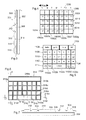
- Fig. 4 depicts a data input/output screen 1000 for selecting dates with the calendar software.
- the date selection screen 1000 comprises a plurality of contiguous data input/output regions 1002, each associated with a unique date number.
- Fig. 4 only explicitly identifies seven of the data input/output regions 1102 (1002a, 1002b, 1002c, 1002d, 1002e, 1002f, 1002g), although, the date selection screen 1000 includes five rows 1006, 1008, 1010, 1012, 1014 of seven data input regions 1002.
- the calendar software interprets data input/output region information, received from the display management software, as a date selection, and displays on the display device 302 appointment information associated with each date corresponding with the date selected.
- Fig. 5 depicts a sample data input/output screen 1100 for text entry with the e-mail or memo software.
- the text entry screen 1100 comprises a plurality of contiguous data input/output regions 1102, each associated with one or more characters (numbers, letters or commands) or words.
- Fig. 5 only explicitly identifies five of the data input/output regions 1102 (1102a, 1102b, 1102c, 1102d, 1102e), although, the text entry screen 1100 includes a first row 1106 of four data input regions 1102, three rows 1108, 1110, 1112 of seven data input regions 1102, and a fifth row 1114 of five data input regions 1102.
- the e-mail/memo software interprets data input/output region information, received from the display management software, as a character selection, and displays on the display device 302 the character associated with the character selected.
- each data input/output region 1002 is surrounded by grid lines 1004 to allow the operator of the communications device 200 to more easily visually identify the lateral extent of each data input/output region 1002.
- each data input/output region 1102 is surrounded by grid lines 1104 to allow the operator of the communications device 200 to more easily visually identify the lateral extent of each data input/output region 1102.
- the grid lines 1004, 1104 may be rendered on the display device 302 by the data processing system and/or permanently configured into the display device 302.
- the data input/output screens may have one or more data input/output regions in common ("common I/O regions"). For instance, the operator of the communications device 200 selects dates for the calendar software via the touch-sensitive screen 304 and also enters characters into the e-mail/memo software via the touch-sensitive screen 304. As shown, each data input/output region 1002 in the second, third and fourth rows 1008, 1010, 1012 of the date selection screen 1000 depicts at most a two-digit number. Similarly, each data input/region 1102 in the second, third and fourth rows 1108, 1110, 1112 of the text entry screen 1100 depicts at most two characters.
- each of the data input regions 1002 in the second, third and fourth rows 1008, 1010, 1012, of the date selection screen 1000 is the same size and occupies the same positions as the corresponding data input/output region 1102 in the second, third and fourth rows 1108, 1110, 1112 of the text entry screen 1100. Therefore, the data input/output regions 1002 in the second, third and fourth rows 1008, 1010, 1012 of the date selection screen 1000 and the corresponding data input/output regions 1102 in the second, third and fourth rows 1108, 1110, 1112 of the text entry screen 1100 each comprise common I/O regions.
- the first two data input/output regions 1102a, 1102b and the last two data input/output regions 1102d, 1102e in the fifth row 1114 of the text entry screen 1100 respectively occupy the same position as the first two data input/output regions 1002a, 1002b and the last two data input/output regions 1002f, 1002g in the fifth row 1014 of the date selection screen 1000.
- the first two and last two data input/output regions 1002a, 1002b, 1002f, 1002g and the corresponding data input/output regions 1102a, 1102b, 1102d, 1102e each comprise common I/O regions.
- the e-mail/memo software may maintain a dictionary/history of commonly-used words, selects from the dictionary/history words that might correspond with the entered character sequence, and causes the display management software to display the selected words on the first row 1106 of the text entry screen 1100. Therefore, the width and number of data input/output regions 1102 in the first row 1106 of the text entry screen 1100 will vary with the length and number of the words selected for display. However, the seven data input/output regions 1002 in the first row 1006 of the date selection screen 1000 together occupy the same position as the data input/output regions 1102 in the first row 1106 of the text entry screen 1100. As a result, the first row 1006 of the date selection screen 1000 and the first row 1106 of the text entry screen 1100 comprise a single common I/O region.
- the space character is one of the most commonly-used characters in the English language
- the space character on an English-language input device, such as keyboard is usually larger than the other keys. Therefore, the data input/output region 1102c in the fifth row 1114 of the text entry screen 1100 that corresponds with the space character occupies the same position as the middle three data input/output regions 1002c, 1002d, 1002e in the fifth row 1014 of the date selection screen 1000.
- the three data input/output regions 1002c, 1002d, 1002e and the single data input/output region 1102c also comprise a single common I/O region.
- the display management software may be configured to detect touch activity at one or more of the common I/O regions with a greater accuracy than the size of respective common I/O region.
- one or more of the common I/O regions may comprise a plurality of data input/output regions whose size and/or position is unique to the associated computer program 258 ("variable I/O regions").
- the common I/O region in the first row 1006 of the date selection screen 1000 may comprise seven fixed-width data input/output regions 1002, whereas the width and number of data input/output regions 1102 in the common I/O region in the first row 1106 of the text entry screen 1100 will vary with the length and number of the words displayed in the first row 1106.
- the data input/output regions 1002 in the first row 1006 of the date selection screen 1000, and the data input/output regions 1102 in the first row 1106 of the text entry screen 1100 each comprise variable I/O regions.
- the display management software can detect and distinguish between touch activity at each of the variable I/O regions in the first row 1006, 1106 even though each of these variable I/O regions is smaller than the common I/O region.
- the data input/output region 1102c in the fifth row 1114 of the text entry screen 1100 that corresponds with the space character has the same width, and occupies the same position as the middle three data input/output regions 1002c, 1002d, 1002e in the fifth row 1014 of the date selection screen 1000. Therefore, the middle three data input/output regions 1002c, 1002d, 1002e each comprise variable I/O regions.
- the display management software can detect and distinguish between touch activity at each of the variable I/O regions in the fifth row 1114 even though each of these variable I/O regions is smaller than the common I/O region 1102c.
- each data input/output region is overlayed by one of the transparent keys of the transparent lens 308 (of the display 300).
- each common I/O region is overlayed by at most one of the transparent keys of the transparent lens 308 (of the display 300).
- the size and shape of each said transparent key matches the size and shape of each corresponding common I/O region.
- the recessed region 312 may align with the lateral extent of each common I/O region.
- the largest variable I/O region in each row and in each column amongst all of the data input/output screens is overlayed by at most one of the transparent keys.
- the size and position of each said transparent key matches the size and shape of each corresponding largest variable I/O region.
- the recessed region 312 may align with the lateral extent of each variable I/O region.
- the transparent lens 308 may include a coloured mask 314 that is incorporated into the recessed region 312, as shown in Figs. 3, 6 and 7 .
- the transparent lens 308 is injection molded using an in-mould decoration (IMD) fabrication process, and the mask 314 is printed onto the transparent lens 308 during IMD fabrication.
- IMD in-mould decoration
- the mask 314 Since the mask 314 is disposed above or separated from the display device 302, the mask 314 creates a parallax difference or apparent angular shift in the position of the recessed regions 312 as the transparent lens 308 is viewed from different angles. As a result, this configuration makes the distinction between the various data I/O regions more visually apparent than if the data processor rendered all the grid lines on the display device 302.
- Fig. 6 is a top plan view of the transparent lens 308, and depicts the configuration of a sample mask 314 that is associated with the sample data input/output screens 1000, 1100.
- Fig. 7 is a transverse cross-sectional view of the display device 302, including the transparent lens 308.
- the mask 314 comprises six horizontal dark-coloured grid lines 316a, 316b, 316c, 316d, 316e, 316f, and eight vertical dark-coloured grid lines 316g, 316h, 316i, 316j, 316k, 3161, 316m, 316n.
- the horizontal grid lines 316a, 316b are respectively aligned with the upper and lower limits of the common I/O regions of the first row 1006 of the date selection screen 1000 and the first row 1106 of the text entry screen 1100.
- the horizontal grid lines 316b, 316c are respectively aligned with the upper and lower limits of the common I/O regions of the second row 1008 of the date selection screen 1000 and the second row 1108 of the text entry screen 1100.
- the horizontal grid lines 316c, 316d are respectively aligned with the upper and lower limits of the common I/O regions of the third row 1010 of the date selection screen 1000 and the third row 1110 of the text entry screen 1100.
- the horizontal grid lines 316d, 316e are respectively aligned with the upper and lower limits of the common I/O regions of the fourth row 1012 of the date selection screen 1000 and the fourth row 1112 of the text entry screen 1100.
- the horizontal grid lines 316e, 316f are respectively aligned with the upper and lower limits of the common I/O regions of the fifth row 1014 of the date selection screen 1000 and the fifth row 1114 of the text entry screen 1100.
- the vertical grid lines 316g, 316h are respectively aligned with left- and right-hand limits of the data input/output regions of the first column of the date selection screen 1000 and the first column of the text entry screen 1100.
- the vertical grid lines 316h, 316i are respectively aligned with left- and right-hand limits of the data input/output regions of the second column of the date selection screen 1000 and the second column of the text entry screen 1100.
- the vertical grid lines 316i, 316j are respectively aligned with left- and right-hand limits of the data input/output regions of the third column of the date selection screen 1000 and the third column of the text entry screen 1100.
- the vertical grid lines 316j, 316k are respectively aligned with left- and right-hand limits of the data input/output regions of the fourth column of the date selection screen 1000 and the fourth column of the text entry screen 1100.
- the vertical grid lines 316k, 3161 are respectively aligned with left- and right-hand limits of the data input/output regions of the fifth column of the date selection screen 1000 and the fifth column of the text entry screen 1100.
- the vertical grid lines 3161, 316m are respectively aligned with left- and right-hand limits of the data input/output regions of the sixth column of the date selection screen 1000 and the sixth column of the text entry screen 1100.
- the vertical grid lines 316m, 316n are respectively aligned with left- and right-hand limits of the data input/output regions of the seventh column of the date selection screen 1000 and the seventh column of the text entry screen 1100.
- the grid lines 316 may align with the lateral extent of each common I/O region and corresponding transparent key. However, preferably none of the grid lines 316 correspond with the lateral extent of the variable I/O regions 1002 in the first row 1006 of the date selection screen 1000, or the lateral extent of the variable I/O regions 1002c, 1002d, 1002e in the fifth row 1014 of the date selection screen 1000. Therefore, the display management software may be configured such that when the calendar program is the active computer program 258, the data processor renders on the display device 302 virtual grid lines between each of the seven variable I/O regions in the first row 1006, and virtual grid lines between the each of variable I/O regions 1002c, 1002d, 1002e.
- the data processor may also render, in the data input/output regions 1002, the date numbers for the month selected by the operator of the communications device 200.
- the image rendered on display 302, below the touch-sensitive screen 304 may match the data input/output screen 1000 shown in Fig. 4 .
- the display management software may be configured such that when the e-mail software or the memo software is the active computer program 258, the data processor renders on the display device 302 virtual grid lines between each of the variable I/O regions 1102 in the first row 1106 of the text entry screen 1100. In this situation, the data processor may also render, in the common I/O and/or the variable I/O regions 1102, the characters of a standard QWERTY keyboard.
- the e-mail/memo software also receives text input from the touch-sensitive screen 304, via the display management software, and may cause the data processor to render, in the variable I/O regions 1102, the words associated with the entered character sequence.
- the image rendered on display device 302, below the touch-sensitive screen 304 may match the data input/output screen 1100 shown in Fig. 5 .
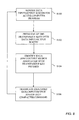
- Fig. 8 is a flow chart that depicts the method of operation of the display 300 and data processing system when the operator of the communication device 200 selects one of the computer programs 258 as the active computer program.
- the display management software renders on the display device 302 the data input/output screen that is associated with the active computer program.
- the data input/output screen comprises a plurality of data input regions. Each data input region is overlayed by one of the transparent keys. As discussed above, one or more of the data input regions may comprise common I/O regions that are common amongst all of the computer programs 258.
- the display management software is configured such that each common I/O region is aligned with a respective transparent key.
- the lateral extent of each common I/O region is identified by a permanent grid line that is formed in the three-dimensional touch-sensitive screen 304 in the recessed region around each associated transparent key.
- the grid lines visually separate the common I/O regions from each other.
- One or more of the data input regions may comprise variable I/O regions whose size and/or position is unique to the active computer program.
- the display management software renders on the display device 302 one or more virtual grid lines that visually separate these variable I/O regions.
- each common I/O region in the active data input/output screen is overlayed by a transparent key, and is optionally surrounded by grid lines that are formed in the three-dimensional touch-sensitive screen 304. Further, the each variable I/O region in the active data input/output screen is surrounded by virtual grid lines that are rendered on the display 302. Therefore, the operator can readily ascertain the lateral extent of each data input/output region.
- the active computer program also renders on the display device 302 characters appropriate to the active computer program.
- the data input/output screen visually associates characters/commands with specified data input/output regions.
- the calendar software is the active computer program
- the computer program renders in numerical order, in the appropriate data input/output regions, the date numbers for the month selected by the operator of the communications device 200.
- the e-mail/memo software is the active computer program
- the computer program renders, in the appropriate data input/output regions, the characters of a standard QWERTY keyboard.
- the user inputs characters/commands into the active computer program by pressing or touching the portion of the transparent key that overlays the data input/output region that is associated with the desired character/command.
- the display management software detects the touch activity (change in pressure or capacitance) at the transparent touch-sensitive panel as a touch input, and identifies the particular data input/output region that is associated with the location of the touch input, at step S104.
- the display management software then passes the identity of the selected data input/output region to the active computer program which, in turn, translates the touch input into the character/command that is visually associated with the selected data input/output region, at step S106.
- the process repeats as long as the communications device 200 is powered on. Therefore, if the operator of the communication device 200 subsequently selects a different one of the computer programs 258 as the active computer program, the display management software renders on the display device 302 the data input/output screen that is associated with the new active computer program. Again, each common I/O region is aligned with a respective transparent key, and the lateral extent of each common I/O region is identified by a grid line that is formed around each associated transparent key.
- the display management software may also render on the display device 302 one or more virtual delimiters that visually separate any variable I/O regions of the active data input/output region.
- the new active computer program then renders on the display device 302 characters appropriate to the active computer program.
- the display management software need not render grid lines around each data input/output region. Instead, the display management software need not render grid lines around each variable I/O region. As a result, the rendering power required to render the different data input/output screens can be reduced in contrast to conventional touch-screen devices.
Landscapes
- Engineering & Computer Science (AREA)
- Theoretical Computer Science (AREA)
- General Engineering & Computer Science (AREA)
- Physics & Mathematics (AREA)
- General Physics & Mathematics (AREA)
- Human Computer Interaction (AREA)
- Optics & Photonics (AREA)
- Computer Hardware Design (AREA)
- User Interface Of Digital Computer (AREA)
- Input From Keyboards Or The Like (AREA)
Abstract
Description
- This disclosure relates to a touch-sensitive display device. In particular, this disclosure relates to a three-dimensional touch-sensitive display device for a portable electronics device.
- Many portable communications devices, such as wireless telephones, personal data assistants, and wireless pagers, include a liquid crystal display (LCD) panel that displays information to the operator of the device, and a physical keyboard for entering commands and/or data into the device. Some portable communications devices have a touch-sensitive screen instead of a separate LCD panel and keyboard. To facilitate entry of data/commands, the device may depict on the touch-sensitive screen a virtual keyboard that comprises a plurality of virtual touch-sensitive keys. Unlike a physical keyboard, however, virtual keyboards do not provide any tactile feedback to the user. As a result, control of the device is often difficult in extremely bright or dim ambient light.
-
Selig (US 6,492,978 ) describes a keyscreen that may be disposed on a LCD or CRT display. The keyscreen comprises a planar touch-screen, and a physical keypad that is disposed over the touch-screen. Computer software, together with the touch-screen and the monitor, defines a virtual keypad over a portion of the display. The physical keypad is fastened to the touch-screen, and comprises a plurality of articulating or flexible opaque or transparent keys that engage a respective portion of the virtual keypad and provide tactile feedback to the user. -
Crandall (US 2004/090428 ) describes an overlay for a touch-sensitive screen. In one embodiment, the overlay comprises a grid of raised portions that are arranged to correspond to the touch-sensitive areas of the screen. In another embodiment, the overlay includes a grid of die-cut holes that are arranged to correspond to the touch-sensitive areas of the screen. -
Maw (US 2006/033723 ) describes a telephone keypad that comprises a touchpad having a perimeter region and a centre region. The centre region comprises a 3x3 matrix of virtual keys, and the perimeter region comprises a ring of virtual keys disposed around the 3x3 key matrix. In one embodiment, the keypad is configured as a touch-screen, and displays the state of the keypad on the touch-screen. In another embodiment, each virtual key of the 3x3 matrix is dome-shaped to provide extra assurance of contacting the appropriate key. - By way of overview, in a first aspect this disclosure relates to a three-dimensional touch-sensitive display device. As will be described in further detail below, the touch-sensitive display comprises a display device, and a transparent three-dimensional touch-sensitive screen that is disposed over the display device. The touch-sensitive screen comprises a plurality of raised regions and a recessed region. The recessed region comprises a printed mask and surrounds the raised regions.
- In one implementation, the touch-sensitive screen comprises a planar transparent touch-sensitive panel, and a three-dimensional transparent lens that is fixed to the touch-sensitive panel. The touch-sensitive panel may comprise a capacitive touch-sensitive panel, with the capacitive touch-sensitive panel being disposed between the transparent lens and the display device. Alternately, the touch-sensitive panel may comprise a resistive touch-sensitive panel, with the transparent lens being disposed between the resistive touch-sensitive panel and the display device. The printed mask may be incorporated onto the transparent lens using an in-mould decoration (IMD) fabrication process or other suitable fabrication processes.
- In a second aspect, this disclosure relates to a portable electronics device that comprises a data processor, and a display. The display is coupled to the data processor and comprises a display device, and a transparent three-dimensional touch-sensitive screen that is disposed over the display device. The touch-sensitive screen comprises a raised region and a recessed region that surrounds the raised region.
- As will be explained, the data processor of the portable electronics device is configured to:
- (i) render on the display device a data input/output screen comprising a plurality of data input regions, the raised region overlaying the data input regions; and
- (ii) detect, as input from one of the data input regions, touch activity at a portion of the raised region coincident with the one data input region.
- The portable electronics device may be implemented as a handheld communications device. In one implementation, the data processor is configured to render on the display device a virtual delimiter aligned with a lateral extent of at least one of the data input regions. The virtual delimiter separates the data input regions. In this implementation, the recessed region comprises a mask that is provided on the touch-sensitive screen. The mask comprises a visual delimiter that is disposed around the data input regions. The touch-sensitive screen comprises a planar transparent touch-sensitive panel, and a three-dimensional transparent lens fixed to the touch-sensitive panel.
- In other implementation, the data processor is configured to depict on the display device a plurality of the data input/output screens, each comprising a plurality of the data input regions. At least one of the data input regions on each data input/output screen is common amongst all of the data input/output screens. The visual delimiter separates the common data input regions. In this implementation, the common data input region of one of the data input/output screens comprises a plurality of the data input regions, and the virtual delimiter separates the data input regions of the common data input region. The touch-sensitive screen comprises a planar transparent touch-sensitive panel, and a three-dimensional transparent lens fixed to the touch-sensitive panel.
- In a third aspect, this disclosure relates to a method of detecting input from a touch-sensitive display. The method may be implemented as a set of computer processing instructions that are stored on a computer-readable medium. The touch-sensitive display may comprise a display device, and a transparent three-dimensional touch-sensitive screen that is disposed over the display device. The touch-sensitive screen comprises a raised region and a recessed region. The recessed region comprises a printed mask that surrounds the raised region.
- As will be described in further detail below, the method involves rendering on the display device a data input/output screen comprising a plurality of data input regions, the raised region overlaying the data input regions, and rendering on the data input/output screen a virtual delimiter separating the data input regions. The method also involves detecting, as input from one of the data input regions, touch activity at a portion of the raised region coincident with the one data input region.
- In one implementation, the rendering step comprises depicting on the display device a plurality of the data input/output screens each comprising a plurality of the data input regions. At least one of the data input regions on each data input/output screen is common amongst all of the data input/output screens. The recessed region comprises a visual delimiter separating the common data input regions. The common data input region of one of the data input/output screens may comprise a plurality of the data input regions, with the virtual delimiter separating the data input regions of the common data input region.
-
-
Fig. 1 is a front plan view of a portable electronics device; -
Fig. 2 is a schematic diagram depicting certain functional details of the portable electronics device, including the display and the data processing system; -
Fig. 3 is a transverse cross-section view of the display, taken along the line 3-3 ofFig. 6 ; -
Fig. 4 depicts a date selection screen when rendered on the display; -
Fig. 5 depicts a text entry screen when rendered on the display; -
Fig. 6 is a top plan view of the display device, depicting a sample mask for use with the date selection and text entry screens; -
Fig. 7 is a transverse cross-sectional view of the display, taken along the line 7-7 ofFig. 6 ; and -
Fig. 8 is a flowchart that depicts the method of operation of the display and the data processing system. - Turning now to
Figs. 1 and2 , there is shown a samplehandheld communications device 200. Preferably, thehandheld communications device 200 is a two-way wireless communications device having at least voice and data communication capabilities, and is configured to operate within a wireless network. Depending on the exact functionality provided, the wirelesshandheld communications device 200 may be referred to as a data messaging device, a two-way pager, a wireless e-mail device, a cellular telephone with data messaging capabilities, a wireless Internet appliance, or a data communication device, as examples. - The
handheld communications device 200 includes a data processing system (not shown), acommunication subsystem 211, adisplay 300, and various other device subsystems and electronics circuits all disposed within a common housing 201. The data processing system, and thedisplay 300 will be discussed in greater detail below. At this point, however, it is sufficient to point out that the data processing system is in communication with the various device subsystems, including thedisplay 300, and controls the overall operation of thecommunications device 200. -
Fig. 2 depicts functional details of thehandheld communications device 200. Thehandheld communications device 200 incorporates a motherboard that includes various device subsystems, such as thecommunication subsystem 211 and the data processing system. Thecommunication subsystem 211 performs communication functions, such as data and voice communications, and includes a primary transmitter/receiver 212, a secondary transmitter/receiver 214, a primaryinternal antenna 216 for the primary transmitter/receiver 212, a secondaryinternal antenna 218 for the secondary transmitter/receiver 214, one or more local oscillators (LOs) 213 and one or more digital signal processors (DSP) 220 coupled to the transmitter/receivers - Typically, the
communication subsystem 211 sends and receives wireless communication signals over a wirelesscellular network 219 via the primary transmitter/receiver 212 and the primaryinternal antenna 216. Further, typically thecommunication subsystem 211 sends and receives wireless communication signals over a wirelesslocal area network 221 via the secondary transmitter/receiver 214 and the secondaryinternal antenna 218. - The primary
internal antenna 216 can be configured for use within a Global System for Mobile Communications (GSM) cellular network or a Code Division Multiple Access (CDMA) cellular network. Further, the secondaryinternal antenna 218 can be configured for use within a WLAN WiFi (IEEE 802.11x) or Bluetooth network. Although thehandheld communications device 200 is depicted inFig. 2 with two antennas, it should be understood that thehandheld communications device 200 may instead comprise only a single antenna, with a dual-band antenna being connected to both the primary transmitter/receiver 212 and the secondary transmitter/receiver 214. - Signals received by the primary
internal antenna 216 from the wirelesscellular network 219 are input to the receiver section of the primary transmitter/receiver 212, which performs common receiver functions such as frequency down conversion, and analog to digital (A/D) conversion, in preparation for more complex communication functions performed by theDSP 220. Signals to be transmitted over the wirelesscellular network 219 are processed by theDSP 220 and input to transmitter section of the primary transmitter/receiver 212 for digital to analog conversion, frequency up conversion, and transmission over the wireless cellular network via the primaryinternal antenna 216. - Similarly, signals received by the secondary
internal antenna 218 from the wirelesslocal area network 221 are input to the receiver section of the secondary transmitter/receiver 214, which performs common receiver functions such as frequency down conversion, and analog to digital (A/D) conversion, in preparation for more complex communication functions performed by theDSP 220. Signals to be transmitted over the wirelesslocal area network 221 are processed by theDSP 220 and input to transmitter section of the secondary transmitter/receiver 214 for digital to analog conversion, frequency up conversion, and transmission over the wireless local area network via the secondaryinternal antenna 218. - The
communications device 200 also includes aSIM interface 244 if thehandheld communications device 200 is configured for use within a GSM network, and/or aRUIM interface 244 if thehandheld communications device 200 is configured for use within a CDMA network. The SIM/RUIM interface 244 is similar to a card-slot into which a SIM/RUIM card can be inserted and ejected. The SIM/RUIM card holds manykey configurations 251, andother information 253 including subscriber identification information, such as the International Mobile Subscriber Identity (IMSI) that is associated with thehandheld communications device 200, and other subscriber-related information. - In data communication mode, a received text message or web page download will be processed by the
communication subsystem 211 and output to thedisplay 300, or alternatively to the auxiliary input/output (I/O)subsystem 228. A user of thehandheld communications device 200 may compose data items such as email messages for example, using thedisplay 300. Such composed items may then be transmitted over the wirelesscellular network 219 or the localarea wireless network 221 through thecommunication subsystem 211. - For voice communications, overall operation of the
handheld communications device 200 is similar, except that received signals would preferably be output to thespeaker 234 and signals for transmission would be generated by amicrophone 236. Further, thedisplay 300 may provide an indication of the identity of a calling party, the duration of a voice call, or other voice call related information for example. - The
display 300 is provided as a self-contained three-dimensional touch-sensitive display that is physically mounted, and electrically connected, to the motherboard. As shown inFigs. 3 and 7 , thedisplay 300 comprises adisplay device 302, and a transparent three-dimensional touch-sensitive screen 304 that is disposed over thedisplay device 302. Thedisplay device 302 and the touch-sensitive screen 304 are coupled to the data processing system. The data processing system displays information to the user via thedisplay device 302, and receives data/command input from the user via the touch-sensitive screen 304. - Preferably, the
display device 302 comprises a planar glass liquid crystal display (LCD) panel, and a printed circuit board (not shown) that carries the display electronics for the display panel. The printed circuit board is coupled to, and controlled by, the data processing system. In addition to the printed circuit board, thedisplay device 302 may include a backlight (not shown), and a light guide (not shown) that is disposed between the backlight and the LCD panel. However, other display devices are encompassed by thedisplay device 302, including reflective and trans-reflective liquid crystal displays, plastic liquid crystal displays (with or without backlight), cathode ray tube (CRT) displays and plasma membrane displays. - The touch-
sensitive screen 304 may be disposed over the entire surface of thedisplay device 302, or only a portion thereof, and is secured to thedisplay device 302 through a mounting frame (not shown) that also secures the assembleddisplay 300 to the motherboard. The touch-sensitive screen 304 comprises a planar transparent touch-sensitive panel306, and a three-dimensionaltransparent lens 308. Preferably, the touch-sensitive panel 306 comprises a capacitive touch-sensitive panel, and is disposed between thetransparent lens 308 and thedisplay device 302. Alternately, the touch-sensitive panel may comprise a resistive touch-sensitive panel, with thetransparent lens 308 being disposed between the resistive touch-sensitive panel and thedisplay device 302. - As shown in
Figs. 3 and 7 , thetransparent lens 308 comprises a plurality of raisedregions 310 and a recessedregion 312. The recessedregion 312 surrounds the raisedregions 310 of thetransparent lens 308, such that the raisedregions 310 appear as distinct transparent keys. - Preferably, the three-dimensional
transparent lens 308 is fabricated from a resilient polymeric material, and is fixed to the touch-sensitive panel 306 via the mounting frame and/or adhesive. Alternately, the three-dimensionaltransparent lens 308 may be integrally-molded with the touch-sensitive panel 306. Thetransparent lens 308 will be discussed in further detail below. - The data processing system interacts with the device subsystems such as the
communication subsystem 211, auxiliary input/output (I/O)subsystem 228,data port 230,speaker 234,microphone 236, short-range communications subsystem 240,device subsystems 242, and thedisplay 300. Thedata port 230 may comprise a RS-232 port, a Universal Serial Bus (USB) port or other wired data communication port. - The data processing system comprises a
microprocessor 238, flash memory 224, and volatile memory (RAM) 226. The flash memory 224 includes bothcomputer program storage 258 andprogram data storage microprocessor 238 from the flash memory 224, implementcomputer programs 258, an operating system, and operating system specific applications. Alternately, the computer processing instructions may be copied from the flash memory 224 into theRAM 226 upon system reset or power-up, and executed by themicroprocessor 238 out of theRAM 226. The computer processing instructions may be installed onto thehandheld communications device 200 upon manufacture, or may be loaded through thewireless networks O subsystem 228, thedata port 230, the short-range communications subsystem 240, or thedevice subsystem 242. - Typically, the
computer programs 258 include communication software that allows thehandheld communications device 200 to receive one or more communication services. For instance, preferably the communication software includes internet browser software, SMS message and e-mail software, telephone software and map software that respectively allow thehandheld communications device 200 to communicate with various computer servers over the Internet, send and receive messages/e-mail, initiate and receive telephone calls, and view electronic maps. Thecomputer programs 258 may also include application software, such as calendar software which diarizes due dates and/or appointments of importance to the user, memo software that allows the user to create and edit memos, and/or task management software that tracks of the status of tasks of importance to the user. - The operating system comprises an Open Systems Interconnection (OSI) communication protocol stack that allows the
handheld communications device 200 to send and receive communication signals over the wirelesscellular network 219 and the localarea wireless network 221. The operating system also allows thehandheld communications device 200 to operate the auxiliary input/output (I/O)subsystem 228,data port 230,speaker 234,microphone 236, short-range communications subsystem 240,device subsystems 242, and thedisplay 300. - The operating system also comprises display management software that configures the data processor to effect data input/output with the
display 300. The display management software is configured with a plurality of data input/output screens, each associated with one of thecomputer programs 258. Each data input/output screen is designed to facilitate data input to the associatedcomputer program 258 from the touch-sensitive screen 304, and to facilitate data output from the associatedcomputer program 258 to thedisplay device 302. The display management software also causes the data processor to render on thedisplay device 302 the data input/output screen for thecomputer program 258 that is currently active (i.e. accepting input from the touch-sensitive screen 304). - Each data input/output screen comprises a plurality of distinct data input/output regions. The display management software is configured to detect touch activity at the touch-
sensitive screen 304 as touch input, and to determine the data input/output region of the active data input/output screen that is associated with the location of the touch input. Possible forms of touch activity include fingertip or stylus pressure on the touch-sensitive screen 304, where thescreen 304 comprises a resistive touch-sensitive panel; and the presence of a fingertip or stylus proximate to the touch-sensitive screen 304, where thescreen 304 comprises a capacitive touch-sensitive panel. - Sample data input/output screens are depicted in
Figs. 4 and 5. Fig. 4 depicts a data input/output screen 1000 for selecting dates with the calendar software. As shown, thedate selection screen 1000 comprises a plurality of contiguous data input/output regions 1002, each associated with a unique date number. For clarity,Fig. 4 only explicitly identifies seven of the data input/output regions 1102 (1002a, 1002b, 1002c, 1002d, 1002e, 1002f, 1002g), although, thedate selection screen 1000 includes fiverows display device 302 appointment information associated with each date corresponding with the date selected. -
Fig. 5 depicts a sample data input/output screen 1100 for text entry with the e-mail or memo software. As shown, thetext entry screen 1100 comprises a plurality of contiguous data input/output regions 1102, each associated with one or more characters (numbers, letters or commands) or words. For clarity,Fig. 5 only explicitly identifies five of the data input/output regions 1102 (1102a, 1102b, 1102c, 1102d, 1102e), although, thetext entry screen 1100 includes afirst row 1106 of four data input regions 1102, threerows fifth row 1114 of five data input regions 1102. The e-mail/memo software interprets data input/output region information, received from the display management software, as a character selection, and displays on thedisplay device 302 the character associated with the character selected. - Preferably, each data input/output region 1002 is surrounded by
grid lines 1004 to allow the operator of thecommunications device 200 to more easily visually identify the lateral extent of each data input/output region 1002. Similarly, preferably each data input/output region 1102 is surrounded bygrid lines 1104 to allow the operator of thecommunications device 200 to more easily visually identify the lateral extent of each data input/output region 1102. As will be explained, thegrid lines display device 302 by the data processing system and/or permanently configured into thedisplay device 302. - The data input/output screens may have one or more data input/output regions in common ("common I/O regions"). For instance, the operator of the
communications device 200 selects dates for the calendar software via the touch-sensitive screen 304 and also enters characters into the e-mail/memo software via the touch-sensitive screen 304. As shown, each data input/output region 1002 in the second, third andfourth rows date selection screen 1000 depicts at most a two-digit number. Similarly, each data input/region 1102 in the second, third andfourth rows text entry screen 1100 depicts at most two characters. With this configuration of data input/output screens, each of the data input regions 1002 in the second, third andfourth rows date selection screen 1000 is the same size and occupies the same positions as the corresponding data input/output region 1102 in the second, third andfourth rows text entry screen 1100. Therefore, the data input/output regions 1002 in the second, third andfourth rows date selection screen 1000 and the corresponding data input/output regions 1102 in the second, third andfourth rows text entry screen 1100 each comprise common I/O regions. - Similarly, the first two data input/
output regions output regions fifth row 1114 of thetext entry screen 1100 respectively occupy the same position as the first two data input/output regions output regions fifth row 1014 of thedate selection screen 1000. As a result, the first two and last two data input/output regions output regions - To ease text entry, the e-mail/memo software may maintain a dictionary/history of commonly-used words, selects from the dictionary/history words that might correspond with the entered character sequence, and causes the display management software to display the selected words on the
first row 1106 of thetext entry screen 1100. Therefore, the width and number of data input/output regions 1102 in thefirst row 1106 of thetext entry screen 1100 will vary with the length and number of the words selected for display. However, the seven data input/output regions 1002 in thefirst row 1006 of thedate selection screen 1000 together occupy the same position as the data input/output regions 1102 in thefirst row 1106 of thetext entry screen 1100. As a result, thefirst row 1006 of thedate selection screen 1000 and thefirst row 1106 of thetext entry screen 1100 comprise a single common I/O region. - Similarly, since the space character is one of the most commonly-used characters in the English language, to ease text entry the space character on an English-language input device, such as keyboard, is usually larger than the other keys. Therefore, the data input/
output region 1102c in thefifth row 1114 of thetext entry screen 1100 that corresponds with the space character occupies the same position as the middle three data input/output regions fifth row 1014 of thedate selection screen 1000. As a result, the three data input/output regions output region 1102c also comprise a single common I/O region. - The display management software may be configured to detect touch activity at one or more of the common I/O regions with a greater accuracy than the size of respective common I/O region. As a result, one or more of the common I/O regions may comprise a plurality of data input/output regions whose size and/or position is unique to the associated computer program 258 ("variable I/O regions"). For example, as discussed, the common I/O region in the
first row 1006 of thedate selection screen 1000 may comprise seven fixed-width data input/output regions 1002, whereas the width and number of data input/output regions 1102 in the common I/O region in thefirst row 1106 of thetext entry screen 1100 will vary with the length and number of the words displayed in thefirst row 1106. Therefore, the data input/output regions 1002 in thefirst row 1006 of thedate selection screen 1000, and the data input/output regions 1102 in thefirst row 1106 of thetext entry screen 1100 each comprise variable I/O regions. The display management software can detect and distinguish between touch activity at each of the variable I/O regions in thefirst row - Similarly, the data input/
output region 1102c in thefifth row 1114 of thetext entry screen 1100 that corresponds with the space character has the same width, and occupies the same position as the middle three data input/output regions fifth row 1014 of thedate selection screen 1000. Therefore, the middle three data input/output regions fifth row 1114 even though each of these variable I/O regions is smaller than the common I/O region 1102c. - To allow the operator of the
communications device 200 to easily identify the lateral extent of each common I/O region, each data input/output region is overlayed by one of the transparent keys of the transparent lens 308 (of the display 300). Preferably, each common I/O region is overlayed by at most one of the transparent keys of the transparent lens 308 (of the display 300). Also, preferably the size and shape of each said transparent key matches the size and shape of each corresponding common I/O region. As a result, the recessedregion 312 may align with the lateral extent of each common I/O region. - Further, to accommodate differences in the size/location of the variable I/O regions amongst the various data input/output screens, while still allowing the operator of the
communications device 200 to easily identify the lateral extent of each data input/output region, preferably the largest variable I/O region in each row and in each column amongst all of the data input/output screens is overlayed by at most one of the transparent keys. Also, preferably the size and position of each said transparent key matches the size and shape of each corresponding largest variable I/O region. As a result, the recessedregion 312 may align with the lateral extent of each variable I/O region. - If the data processor rendered all the dark-coloured grid lines of all the data input/output screens on the
display device 302, computing power of the data processor would be wasted rendering grid lines as eachnew computer program 258 became active. To avoid having to render all of these grid lines, without obscuring the lateral extent of each data input/output region and each transparent key, thetransparent lens 308 may include acoloured mask 314 that is incorporated into the recessedregion 312, as shown inFigs. 3, 6 and 7 . Preferably, thetransparent lens 308 is injection molded using an in-mould decoration (IMD) fabrication process, and themask 314 is printed onto thetransparent lens 308 during IMD fabrication. Since themask 314 is disposed above or separated from thedisplay device 302, themask 314 creates a parallax difference or apparent angular shift in the position of the recessedregions 312 as thetransparent lens 308 is viewed from different angles. As a result, this configuration makes the distinction between the various data I/O regions more visually apparent than if the data processor rendered all the grid lines on thedisplay device 302. -
Fig. 6 is a top plan view of thetransparent lens 308, and depicts the configuration of asample mask 314 that is associated with the sample data input/output screens Fig. 7 is a transverse cross-sectional view of thedisplay device 302, including thetransparent lens 308. As shown, themask 314 comprises six horizontal dark-coloured grid lines coloured grid lines - The
horizontal grid lines first row 1006 of thedate selection screen 1000 and thefirst row 1106 of thetext entry screen 1100. Thehorizontal grid lines second row 1008 of thedate selection screen 1000 and thesecond row 1108 of thetext entry screen 1100. Thehorizontal grid lines third row 1010 of thedate selection screen 1000 and thethird row 1110 of thetext entry screen 1100. Thehorizontal grid lines fourth row 1012 of thedate selection screen 1000 and thefourth row 1112 of thetext entry screen 1100. Thehorizontal grid lines fifth row 1014 of thedate selection screen 1000 and thefifth row 1114 of thetext entry screen 1100. - The
vertical grid lines 316g, 316h are respectively aligned with left- and right-hand limits of the data input/output regions of the first column of thedate selection screen 1000 and the first column of thetext entry screen 1100. Thevertical grid lines 316h, 316i are respectively aligned with left- and right-hand limits of the data input/output regions of the second column of thedate selection screen 1000 and the second column of thetext entry screen 1100. Thevertical grid lines 316i, 316j are respectively aligned with left- and right-hand limits of the data input/output regions of the third column of thedate selection screen 1000 and the third column of thetext entry screen 1100. The vertical grid lines 316j, 316k are respectively aligned with left- and right-hand limits of the data input/output regions of the fourth column of thedate selection screen 1000 and the fourth column of thetext entry screen 1100. The vertical grid lines 316k, 3161 are respectively aligned with left- and right-hand limits of the data input/output regions of the fifth column of thedate selection screen 1000 and the fifth column of thetext entry screen 1100. The vertical grid lines 3161, 316m are respectively aligned with left- and right-hand limits of the data input/output regions of the sixth column of thedate selection screen 1000 and the sixth column of thetext entry screen 1100. Thevertical grid lines 316m, 316n are respectively aligned with left- and right-hand limits of the data input/output regions of the seventh column of thedate selection screen 1000 and the seventh column of thetext entry screen 1100. - As a result, the
grid lines 316 may align with the lateral extent of each common I/O region and corresponding transparent key. However, preferably none of thegrid lines 316 correspond with the lateral extent of the variable I/O regions 1002 in thefirst row 1006 of thedate selection screen 1000, or the lateral extent of the variable I/O regions fifth row 1014 of thedate selection screen 1000. Therefore, the display management software may be configured such that when the calendar program is theactive computer program 258, the data processor renders on thedisplay device 302 virtual grid lines between each of the seven variable I/O regions in thefirst row 1006, and virtual grid lines between the each of variable I/O regions communications device 200. As a result, the image rendered ondisplay 302, below the touch-sensitive screen 304, may match the data input/output screen 1000 shown inFig. 4 . - Similarly, preferably none of the
grid lines 316 correspond with the lateral extent of the variable I/O regions 1102 in thefirst row 1106 of thetext entry screen 1100. Therefore, the display management software may be configured such that when the e-mail software or the memo software is theactive computer program 258, the data processor renders on thedisplay device 302 virtual grid lines between each of the variable I/O regions 1102 in thefirst row 1106 of thetext entry screen 1100. In this situation, the data processor may also render, in the common I/O and/or the variable I/O regions 1102, the characters of a standard QWERTY keyboard. The e-mail/memo software also receives text input from the touch-sensitive screen 304, via the display management software, and may cause the data processor to render, in the variable I/O regions 1102, the words associated with the entered character sequence. As a result, the image rendered ondisplay device 302, below the touch-sensitive screen 304, may match the data input/output screen 1100 shown inFig. 5 . -
Fig. 8 is a flow chart that depicts the method of operation of thedisplay 300 and data processing system when the operator of thecommunication device 200 selects one of thecomputer programs 258 as the active computer program. - At step S100, the display management software renders on the
display device 302 the data input/output screen that is associated with the active computer program. The data input/output screen comprises a plurality of data input regions. Each data input region is overlayed by one of the transparent keys. As discussed above, one or more of the data input regions may comprise common I/O regions that are common amongst all of thecomputer programs 258. - The display management software is configured such that each common I/O region is aligned with a respective transparent key. Preferably, the lateral extent of each common I/O region is identified by a permanent grid line that is formed in the three-dimensional touch-
sensitive screen 304 in the recessed region around each associated transparent key. As a result, the grid lines visually separate the common I/O regions from each other. - One or more of the data input regions may comprise variable I/O regions whose size and/or position is unique to the active computer program. Where a common I/O region comprises a plurality of variable I/O regions, the display management software renders on the
display device 302 one or more virtual grid lines that visually separate these variable I/O regions. - As a result, each common I/O region in the active data input/output screen is overlayed by a transparent key, and is optionally surrounded by grid lines that are formed in the three-dimensional touch-
sensitive screen 304. Further, the each variable I/O region in the active data input/output screen is surrounded by virtual grid lines that are rendered on thedisplay 302. Therefore, the operator can readily ascertain the lateral extent of each data input/output region. - At step S100, the active computer program also renders on the
display device 302 characters appropriate to the active computer program. As a result, the data input/output screen visually associates characters/commands with specified data input/output regions. For instance, where the calendar software is the active computer program, the computer program renders in numerical order, in the appropriate data input/output regions, the date numbers for the month selected by the operator of thecommunications device 200. Where the e-mail/memo software is the active computer program, the computer program renders, in the appropriate data input/output regions, the characters of a standard QWERTY keyboard. - Thereafter, at step S102, the user inputs characters/commands into the active computer program by pressing or touching the portion of the transparent key that overlays the data input/output region that is associated with the desired character/command. The display management software detects the touch activity (change in pressure or capacitance) at the transparent touch-sensitive panel as a touch input, and identifies the particular data input/output region that is associated with the location of the touch input, at step S104. The display management software then passes the identity of the selected data input/output region to the active computer program which, in turn, translates the touch input into the character/command that is visually associated with the selected data input/output region, at step S106.
- The process repeats as long as the
communications device 200 is powered on. Therefore, if the operator of thecommunication device 200 subsequently selects a different one of thecomputer programs 258 as the active computer program, the display management software renders on thedisplay device 302 the data input/output screen that is associated with the new active computer program. Again, each common I/O region is aligned with a respective transparent key, and the lateral extent of each common I/O region is identified by a grid line that is formed around each associated transparent key. The display management software may also render on thedisplay device 302 one or more virtual delimiters that visually separate any variable I/O regions of the active data input/output region. The new active computer program then renders on thedisplay device 302 characters appropriate to the active computer program. However, since the lateral extent of the common I/O regions are identified by grid lines that are permanently formed around each associated transparent key, the display management software need not render grid lines around each data input/output region. Instead, the display management software need not render grid lines around each variable I/O region. As a result, the rendering power required to render the different data input/output screens can be reduced in contrast to conventional touch-screen devices.
Claims (15)
- A portable electronics device comprising:a data processor; anda display coupled to the data processor, the display comprising:a display device; anda transparent three-dimensional touch-sensitive screen disposed over a portion of the display device, the touch-sensitive screen comprising a raised region and a recessed region surrounding the raised region, the data processor being configured to:(i) render on the display device a data input/output screen comprising a plurality of data input regions, the raised region overlaying the data input regions; and(ii) detect, as input from one of the data input regions, touch activity at a portion of the raised region coincident with the one data input region.
- The portable electronics device according to Claim 1, wherein the data processor is configured to render on the display device a virtual delimiter aligned with a lateral extent of at least one of the data input regions, the virtual delimiter separating the data input regions.
- The portable electronics device according to Claim 1 or Claim 2, wherein the recessed region comprises a mask provided on the touch-sensitive screen, the mask comprising a visual delimiter disposed around the data input regions.
- The portable electronics device according to Claim 3, wherein the data processor is configured to depict on the display device a plurality of the data input/output screens, each said data input/output screen comprising a plurality of the data input regions, at least one of the data input regions on each said data input/output screen being common amongst all of the data input/output screens, the visual delimiter separating the common data input regions.
- The portable electronics device according to Claim 4, wherein the common data input region of one of the data input/output screens comprises a plurality of the data input regions, the virtual delimiter separating the data input regions of the common data input region.
- The portable electronics device according to any of Claims 1 to 5, wherein the touch-sensitive screen comprises a planar transparent touch-sensitive panel, and a three-dimensional transparent lens fixed to the touch-sensitive panel.
- A method of detecting input from a touch-sensitive display, the touch-sensitive display comprising a display device, and a transparent three-dimensional touch-sensitive screen disposed over the display device, the touch-sensitive screen comprising a raised region and a recessed region surrounding the raised region, the method comprising:rendering on the display device a data input/output screen comprising a plurality of data input regions, the raised region overlaying the data input regions, and rendering on the data input/output screen a virtual delimiter separating the data input regions; anddetecting, as input from one of the data input regions, touch activity at a portion of the raised region coincident with the one data input region.
- The method according to Claim 7, wherein the rendering step comprises depicting on the display device a plurality of the data input/output screens each comprising a plurality of the data input regions, at least one of the data input regions on each said data input/output screen being common amongst all of the data input/output screens, and the recessed region comprises a visual delimiter separating the common data input regions.
- The method according to Claim 8, wherein the common data input region of one of the data input/output screens comprises a plurality of the data input regions, the virtual delimiter separating the data input regions of the common data input region.
- A computer-readable medium carrying processing instructions for an electronics device, the processing instructions when executed by a processor of the electronics device causing the electronics device to perform the steps of the method of any one of Claims 7 to 9.
- A three-dimensional touch-sensitive display comprising:a display device; anda transparent three-dimensional touch-sensitive screen disposed over the display device, the touch-sensitive screen comprising a plurality of raised regions and a recessed region surrounding the raised regions, the recessed region comprising a printed mask.
- The three-dimensional touch-sensitive display according to Claim 11, wherein the touch-sensitive screen comprises a planar transparent touch-sensitive panel, and a three-dimensional transparent lens fixed to the touch-sensitive panel.
- The three-dimensional touch-sensitive display according to Claim 12, wherein the touch-sensitive panel comprises a capacitive touch-sensitive panel, and the capacitive touch-sensitive panel is disposed between the transparent lens and the display device.
- The three-dimensional touch-sensitive display according to Claim 12, wherein the touch-sensitive panel comprises a resistive touch-sensitive panel, and the transparent lens is disposed between the resistive touch-sensitive panel and the display device.
- The three-dimensional touch-sensitive display according to any one of Claims 12 to 14, wherein the printed mask is incorporated onto the transparent lens using an in-mould decoration (IMD) fabrication process.
Priority Applications (3)
| Application Number | Priority Date | Filing Date | Title |
|---|---|---|---|
| EP08151395A EP2090971B1 (en) | 2008-02-13 | 2008-02-13 | Three-dimensional touch-sensitive display device |
| CA002653858A CA2653858A1 (en) | 2008-02-13 | 2009-02-12 | Three-dimensional touch-sensitive display device |
| KR1020090012000A KR101114642B1 (en) | 2008-02-13 | 2009-02-13 | Three-dimensional touch-sensitive display device |
Applications Claiming Priority (1)
| Application Number | Priority Date | Filing Date | Title |
|---|---|---|---|
| EP08151395A EP2090971B1 (en) | 2008-02-13 | 2008-02-13 | Three-dimensional touch-sensitive display device |
Publications (2)
| Publication Number | Publication Date |
|---|---|
| EP2090971A1 true EP2090971A1 (en) | 2009-08-19 |
| EP2090971B1 EP2090971B1 (en) | 2012-06-27 |
Family
ID=39488293
Family Applications (1)
| Application Number | Title | Priority Date | Filing Date |
|---|---|---|---|
| EP08151395A Active EP2090971B1 (en) | 2008-02-13 | 2008-02-13 | Three-dimensional touch-sensitive display device |
Country Status (3)
| Country | Link |
|---|---|
| EP (1) | EP2090971B1 (en) |
| KR (1) | KR101114642B1 (en) |
| CA (1) | CA2653858A1 (en) |
Cited By (3)
| Publication number | Priority date | Publication date | Assignee | Title |
|---|---|---|---|---|
| WO2012020379A1 (en) * | 2010-08-13 | 2012-02-16 | Nokia Corporation | A cover for an electronic device |
| WO2012047835A1 (en) * | 2010-10-04 | 2012-04-12 | Dresser, Inc. | A display assembly and a fuel dispensing unit |
| EP2772835A1 (en) * | 2013-02-27 | 2014-09-03 | Wintek (China) Technology Ltd. | Touch-sensitive panel |
Families Citing this family (1)
| Publication number | Priority date | Publication date | Assignee | Title |
|---|---|---|---|---|
| US9804709B2 (en) * | 2015-04-28 | 2017-10-31 | Samsung Display Co., Ltd. | Vector fill segment method and apparatus to reduce display latency of touch events |
Citations (7)
| Publication number | Priority date | Publication date | Assignee | Title |
|---|---|---|---|---|
| US6259044B1 (en) | 2000-03-03 | 2001-07-10 | Intermec Ip Corporation | Electronic device with tactile keypad-overlay |
| US20030081016A1 (en) * | 2001-10-31 | 2003-05-01 | Genovation Inc. | Personal digital assistant mouse |
| US20030235452A1 (en) | 2002-06-21 | 2003-12-25 | Microsoft Corporation | Method and system for using a keyboard overlay with a touch-sensitive display screen |
| EP1548544A2 (en) | 2003-11-18 | 2005-06-29 | Kabushiki Kaisha Toshiba | Electronic device with a rotating and translating display |
| US20060265648A1 (en) * | 2005-05-23 | 2006-11-23 | Roope Rainisto | Electronic text input involving word completion functionality for predicting word candidates for partial word inputs |
| US20070152975A1 (en) | 2004-02-10 | 2007-07-05 | Takuya Ogihara | Touch screen-type input device |
| US20070279391A1 (en) * | 2006-06-06 | 2007-12-06 | Marttila Charles A | Keypad with virtual image |
Family Cites Families (1)
| Publication number | Priority date | Publication date | Assignee | Title |
|---|---|---|---|---|
| WO2000057266A1 (en) * | 1999-03-23 | 2000-09-28 | British Telecommunications Public Limited Company | Computer input device |
-
2008
- 2008-02-13 EP EP08151395A patent/EP2090971B1/en active Active
-
2009
- 2009-02-12 CA CA002653858A patent/CA2653858A1/en not_active Abandoned
- 2009-02-13 KR KR1020090012000A patent/KR101114642B1/en active Active
Patent Citations (7)
| Publication number | Priority date | Publication date | Assignee | Title |
|---|---|---|---|---|
| US6259044B1 (en) | 2000-03-03 | 2001-07-10 | Intermec Ip Corporation | Electronic device with tactile keypad-overlay |
| US20030081016A1 (en) * | 2001-10-31 | 2003-05-01 | Genovation Inc. | Personal digital assistant mouse |
| US20030235452A1 (en) | 2002-06-21 | 2003-12-25 | Microsoft Corporation | Method and system for using a keyboard overlay with a touch-sensitive display screen |
| EP1548544A2 (en) | 2003-11-18 | 2005-06-29 | Kabushiki Kaisha Toshiba | Electronic device with a rotating and translating display |
| US20070152975A1 (en) | 2004-02-10 | 2007-07-05 | Takuya Ogihara | Touch screen-type input device |
| US20060265648A1 (en) * | 2005-05-23 | 2006-11-23 | Roope Rainisto | Electronic text input involving word completion functionality for predicting word candidates for partial word inputs |
| US20070279391A1 (en) * | 2006-06-06 | 2007-12-06 | Marttila Charles A | Keypad with virtual image |
Cited By (7)
| Publication number | Priority date | Publication date | Assignee | Title |
|---|---|---|---|---|
| WO2012020379A1 (en) * | 2010-08-13 | 2012-02-16 | Nokia Corporation | A cover for an electronic device |
| CN103097980A (en) * | 2010-08-13 | 2013-05-08 | 诺基亚公司 | A cover for an electronic device |
| US9041661B2 (en) | 2010-08-13 | 2015-05-26 | Nokia Corporation | Cover for an electronic device |
| CN103097980B (en) * | 2010-08-13 | 2017-05-10 | 诺基亚技术有限公司 | A cover for an electronic device |
| WO2012047835A1 (en) * | 2010-10-04 | 2012-04-12 | Dresser, Inc. | A display assembly and a fuel dispensing unit |
| US8531404B2 (en) | 2010-10-04 | 2013-09-10 | Dresser, Inc. | Display assembly and a fuel dispensing unit |
| EP2772835A1 (en) * | 2013-02-27 | 2014-09-03 | Wintek (China) Technology Ltd. | Touch-sensitive panel |
Also Published As
| Publication number | Publication date |
|---|---|
| KR101114642B1 (en) | 2012-03-05 |
| EP2090971B1 (en) | 2012-06-27 |
| KR20090087841A (en) | 2009-08-18 |
| CA2653858A1 (en) | 2009-08-13 |
Similar Documents
| Publication | Publication Date | Title |
|---|---|---|
| EP2000885B1 (en) | Haptic display for a handheld electronic device | |
| CN112527431B (en) | A widget processing method and related device | |
| US11029827B2 (en) | Text selection using a touch sensitive screen of a handheld mobile communication device | |
| US20080303795A1 (en) | Haptic display for a handheld electronic device | |
| EP2000884A1 (en) | Shape-changing disply for a handheld electronic device | |
| US20080303796A1 (en) | Shape-changing display for a handheld electronic device | |
| EP3101519B1 (en) | Systems and methods for providing a user interface | |
| US8289286B2 (en) | Zooming keyboard/keypad | |
| EP1903422B1 (en) | Lightguide subassembly for receiving a trackball navigational tool mountable within a handheld mobile device | |
| US9692881B2 (en) | Electronic device, information processing method and information display method | |
| US7552142B2 (en) | On-screen diagonal cursor navigation on a handheld communication device having a reduced alphabetic keyboard | |
| EP2701033B1 (en) | Temporary keyboard having some individual keys that provide varying levels of capacitive coupling to a touch-sensitive display | |
| US8822851B2 (en) | Method and apparatus for controlling a multi-mode keyboard | |
| US20100088628A1 (en) | Live preview of open windows | |
| KR20110056315A (en) | How to pan and zoom an image on a portable touch-sensitive display | |
| JP5371712B2 (en) | Key input device and portable terminal | |
| US20120144337A1 (en) | Adjustable touch screen keyboard | |
| KR101973334B1 (en) | Electronic apparatus and method for controlling display screen of electronic apparatus | |
| WO2007084078A1 (en) | A keyboard for a mobile phone or other portable communication devices | |
| EP2090971B1 (en) | Three-dimensional touch-sensitive display device | |
| US20090167695A1 (en) | Embedded navigation assembly and method on handheld device | |
| EP2259555A1 (en) | Communication device, method for displaying function of communication device, and recording medium of program for communication device | |
| US20090201258A1 (en) | Three-dimensional touch-sensitive display device | |
| WO2010056391A1 (en) | Method and apparatus for providing a user interface on a mobile device | |
| KR20080093478A (en) | Terminal and its display method |
Legal Events
| Date | Code | Title | Description |
|---|---|---|---|
| PUAI | Public reference made under article 153(3) epc to a published international application that has entered the european phase |
Free format text: ORIGINAL CODE: 0009012 |
|
| 17P | Request for examination filed |
Effective date: 20080213 |
|
| AK | Designated contracting states |
Kind code of ref document: A1 Designated state(s): AT BE BG CH CY CZ DE DK EE ES FI FR GB GR HR HU IE IS IT LI LT LU LV MC MT NL NO PL PT RO SE SI SK TR |
|
| AX | Request for extension of the european patent |
Extension state: AL BA MK RS |
|
| AKX | Designation fees paid |
Designated state(s): AT BE BG CH CY CZ DE DK EE ES FI FR GB GR HR HU IE IS IT LI LT LU LV MC MT NL NO PL PT RO SE SI SK TR |
|
| AXX | Extension fees paid |
Extension state: BA Payment date: 20080213 Extension state: AL Payment date: 20080213 Extension state: MK Payment date: 20080213 Extension state: RS Payment date: 20080213 |
|
| GRAP | Despatch of communication of intention to grant a patent |
Free format text: ORIGINAL CODE: EPIDOSNIGR1 |
|
| GRAS | Grant fee paid |
Free format text: ORIGINAL CODE: EPIDOSNIGR3 |
|
| GRAA | (expected) grant |
Free format text: ORIGINAL CODE: 0009210 |
|
| AK | Designated contracting states |
Kind code of ref document: B1 Designated state(s): AT BE BG CH CY CZ DE DK EE ES FI FR GB GR HR HU IE IS IT LI LT LU LV MC MT NL NO PL PT RO SE SI SK TR |
|
| AX | Request for extension of the european patent |
Extension state: AL BA MK RS |
|
| REG | Reference to a national code |
Ref country code: GB Ref legal event code: FG4D |
|
| REG | Reference to a national code |
Ref country code: CH Ref legal event code: EP |
|
| REG | Reference to a national code |
Ref country code: AT Ref legal event code: REF Ref document number: 564536 Country of ref document: AT Kind code of ref document: T Effective date: 20120715 |
|
| REG | Reference to a national code |
Ref country code: IE Ref legal event code: FG4D |
|
| REG | Reference to a national code |
Ref country code: DE Ref legal event code: R096 Ref document number: 602008016673 Country of ref document: DE Effective date: 20120823 |
|
| PG25 | Lapsed in a contracting state [announced via postgrant information from national office to epo] |
Ref country code: NO Free format text: LAPSE BECAUSE OF FAILURE TO SUBMIT A TRANSLATION OF THE DESCRIPTION OR TO PAY THE FEE WITHIN THE PRESCRIBED TIME-LIMIT Effective date: 20120927 Ref country code: LT Free format text: LAPSE BECAUSE OF FAILURE TO SUBMIT A TRANSLATION OF THE DESCRIPTION OR TO PAY THE FEE WITHIN THE PRESCRIBED TIME-LIMIT Effective date: 20120627 Ref country code: SE Free format text: LAPSE BECAUSE OF FAILURE TO SUBMIT A TRANSLATION OF THE DESCRIPTION OR TO PAY THE FEE WITHIN THE PRESCRIBED TIME-LIMIT Effective date: 20120627 Ref country code: FI Free format text: LAPSE BECAUSE OF FAILURE TO SUBMIT A TRANSLATION OF THE DESCRIPTION OR TO PAY THE FEE WITHIN THE PRESCRIBED TIME-LIMIT Effective date: 20120627 |
|
| REG | Reference to a national code |
Ref country code: NL Ref legal event code: T3 |
|
| REG | Reference to a national code |
Ref country code: AT Ref legal event code: MK05 Ref document number: 564536 Country of ref document: AT Kind code of ref document: T Effective date: 20120627 |
|
| REG | Reference to a national code |
Ref country code: LT Ref legal event code: MG4D Effective date: 20120627 |
|
| PG25 | Lapsed in a contracting state [announced via postgrant information from national office to epo] |
Ref country code: LV Free format text: LAPSE BECAUSE OF FAILURE TO SUBMIT A TRANSLATION OF THE DESCRIPTION OR TO PAY THE FEE WITHIN THE PRESCRIBED TIME-LIMIT Effective date: 20120627 Ref country code: GR Free format text: LAPSE BECAUSE OF FAILURE TO SUBMIT A TRANSLATION OF THE DESCRIPTION OR TO PAY THE FEE WITHIN THE PRESCRIBED TIME-LIMIT Effective date: 20120928 Ref country code: HR Free format text: LAPSE BECAUSE OF FAILURE TO SUBMIT A TRANSLATION OF THE DESCRIPTION OR TO PAY THE FEE WITHIN THE PRESCRIBED TIME-LIMIT Effective date: 20120627 Ref country code: SI Free format text: LAPSE BECAUSE OF FAILURE TO SUBMIT A TRANSLATION OF THE DESCRIPTION OR TO PAY THE FEE WITHIN THE PRESCRIBED TIME-LIMIT Effective date: 20120627 |
|
| PG25 | Lapsed in a contracting state [announced via postgrant information from national office to epo] |
Ref country code: AT Free format text: LAPSE BECAUSE OF FAILURE TO SUBMIT A TRANSLATION OF THE DESCRIPTION OR TO PAY THE FEE WITHIN THE PRESCRIBED TIME-LIMIT Effective date: 20120627 Ref country code: EE Free format text: LAPSE BECAUSE OF FAILURE TO SUBMIT A TRANSLATION OF THE DESCRIPTION OR TO PAY THE FEE WITHIN THE PRESCRIBED TIME-LIMIT Effective date: 20120627 Ref country code: RO Free format text: LAPSE BECAUSE OF FAILURE TO SUBMIT A TRANSLATION OF THE DESCRIPTION OR TO PAY THE FEE WITHIN THE PRESCRIBED TIME-LIMIT Effective date: 20120627 Ref country code: SK Free format text: LAPSE BECAUSE OF FAILURE TO SUBMIT A TRANSLATION OF THE DESCRIPTION OR TO PAY THE FEE WITHIN THE PRESCRIBED TIME-LIMIT Effective date: 20120627 Ref country code: CY Free format text: LAPSE BECAUSE OF FAILURE TO SUBMIT A TRANSLATION OF THE DESCRIPTION OR TO PAY THE FEE WITHIN THE PRESCRIBED TIME-LIMIT Effective date: 20120627 Ref country code: CZ Free format text: LAPSE BECAUSE OF FAILURE TO SUBMIT A TRANSLATION OF THE DESCRIPTION OR TO PAY THE FEE WITHIN THE PRESCRIBED TIME-LIMIT Effective date: 20120627 Ref country code: BE Free format text: LAPSE BECAUSE OF FAILURE TO SUBMIT A TRANSLATION OF THE DESCRIPTION OR TO PAY THE FEE WITHIN THE PRESCRIBED TIME-LIMIT Effective date: 20120627 Ref country code: IS Free format text: LAPSE BECAUSE OF FAILURE TO SUBMIT A TRANSLATION OF THE DESCRIPTION OR TO PAY THE FEE WITHIN THE PRESCRIBED TIME-LIMIT Effective date: 20121027 |
|
| PG25 | Lapsed in a contracting state [announced via postgrant information from national office to epo] |
Ref country code: PT Free format text: LAPSE BECAUSE OF FAILURE TO SUBMIT A TRANSLATION OF THE DESCRIPTION OR TO PAY THE FEE WITHIN THE PRESCRIBED TIME-LIMIT Effective date: 20121029 Ref country code: PL Free format text: LAPSE BECAUSE OF FAILURE TO SUBMIT A TRANSLATION OF THE DESCRIPTION OR TO PAY THE FEE WITHIN THE PRESCRIBED TIME-LIMIT Effective date: 20120627 Ref country code: IT Free format text: LAPSE BECAUSE OF FAILURE TO SUBMIT A TRANSLATION OF THE DESCRIPTION OR TO PAY THE FEE WITHIN THE PRESCRIBED TIME-LIMIT Effective date: 20120627 |
|
| PG25 | Lapsed in a contracting state [announced via postgrant information from national office to epo] |
Ref country code: ES Free format text: LAPSE BECAUSE OF FAILURE TO SUBMIT A TRANSLATION OF THE DESCRIPTION OR TO PAY THE FEE WITHIN THE PRESCRIBED TIME-LIMIT Effective date: 20121008 Ref country code: DK Free format text: LAPSE BECAUSE OF FAILURE TO SUBMIT A TRANSLATION OF THE DESCRIPTION OR TO PAY THE FEE WITHIN THE PRESCRIBED TIME-LIMIT Effective date: 20120627 |
|
| PLBE | No opposition filed within time limit |
Free format text: ORIGINAL CODE: 0009261 |
|
| STAA | Information on the status of an ep patent application or granted ep patent |
Free format text: STATUS: NO OPPOSITION FILED WITHIN TIME LIMIT |
|
| 26N | No opposition filed |
Effective date: 20130328 |
|
| REG | Reference to a national code |
Ref country code: DE Ref legal event code: R097 Ref document number: 602008016673 Country of ref document: DE Effective date: 20130328 |
|
| PG25 | Lapsed in a contracting state [announced via postgrant information from national office to epo] |
Ref country code: BG Free format text: LAPSE BECAUSE OF FAILURE TO SUBMIT A TRANSLATION OF THE DESCRIPTION OR TO PAY THE FEE WITHIN THE PRESCRIBED TIME-LIMIT Effective date: 20120927 |
|
| PG25 | Lapsed in a contracting state [announced via postgrant information from national office to epo] |
Ref country code: MC Free format text: LAPSE BECAUSE OF NON-PAYMENT OF DUE FEES Effective date: 20130228 |
|
| REG | Reference to a national code |
Ref country code: CH Ref legal event code: PL |
|
| PG25 | Lapsed in a contracting state [announced via postgrant information from national office to epo] |
Ref country code: LI Free format text: LAPSE BECAUSE OF NON-PAYMENT OF DUE FEES Effective date: 20130228 Ref country code: CH Free format text: LAPSE BECAUSE OF NON-PAYMENT OF DUE FEES Effective date: 20130228 |
|
| REG | Reference to a national code |
Ref country code: IE Ref legal event code: MM4A |
|
| PG25 | Lapsed in a contracting state [announced via postgrant information from national office to epo] |
Ref country code: IE Free format text: LAPSE BECAUSE OF NON-PAYMENT OF DUE FEES Effective date: 20130213 |
|
| PG25 | Lapsed in a contracting state [announced via postgrant information from national office to epo] |
Ref country code: MT Free format text: LAPSE BECAUSE OF FAILURE TO SUBMIT A TRANSLATION OF THE DESCRIPTION OR TO PAY THE FEE WITHIN THE PRESCRIBED TIME-LIMIT Effective date: 20120627 |
|
| REG | Reference to a national code |
Ref country code: DE Ref legal event code: R082 Ref document number: 602008016673 Country of ref document: DE Representative=s name: MERH-IP MATIAS ERNY REICHL HOFFMANN, DE |
|
| REG | Reference to a national code |
Ref country code: DE Ref legal event code: R082 Ref document number: 602008016673 Country of ref document: DE Representative=s name: MERH-IP MATIAS ERNY REICHL HOFFMANN, DE Effective date: 20140926 Ref country code: DE Ref legal event code: R081 Ref document number: 602008016673 Country of ref document: DE Owner name: BLACKBERRY LIMITED, WATERLOO, CA Free format text: FORMER OWNER: RESEARCH IN MOTION LIMITED, WATERLOO, ONTARIO, CA Effective date: 20140926 Ref country code: DE Ref legal event code: R082 Ref document number: 602008016673 Country of ref document: DE Representative=s name: MERH-IP MATIAS ERNY REICHL HOFFMANN PATENTANWA, DE Effective date: 20140926 |
|
| PG25 | Lapsed in a contracting state [announced via postgrant information from national office to epo] |
Ref country code: TR Free format text: LAPSE BECAUSE OF FAILURE TO SUBMIT A TRANSLATION OF THE DESCRIPTION OR TO PAY THE FEE WITHIN THE PRESCRIBED TIME-LIMIT Effective date: 20120627 |
|
| PG25 | Lapsed in a contracting state [announced via postgrant information from national office to epo] |
Ref country code: LU Free format text: LAPSE BECAUSE OF NON-PAYMENT OF DUE FEES Effective date: 20130213 Ref country code: HU Free format text: LAPSE BECAUSE OF FAILURE TO SUBMIT A TRANSLATION OF THE DESCRIPTION OR TO PAY THE FEE WITHIN THE PRESCRIBED TIME-LIMIT; INVALID AB INITIO Effective date: 20080213 |
|
| REG | Reference to a national code |
Ref country code: FR Ref legal event code: PLFP Year of fee payment: 9 |
|
| REG | Reference to a national code |
Ref country code: FR Ref legal event code: PLFP Year of fee payment: 10 |
|
| REG | Reference to a national code |
Ref country code: FR Ref legal event code: PLFP Year of fee payment: 11 |
|
| REG | Reference to a national code |
Ref country code: DE Ref legal event code: R082 Ref document number: 602008016673 Country of ref document: DE Ref country code: DE Ref legal event code: R081 Ref document number: 602008016673 Country of ref document: DE Owner name: MALIKIE INNOVATIONS LTD., IE Free format text: FORMER OWNER: BLACKBERRY LIMITED, WATERLOO, ONTARIO, CA |
|
| PGFP | Annual fee paid to national office [announced via postgrant information from national office to epo] |
Ref country code: NL Payment date: 20260220 Year of fee payment: 19 |
|
| PGFP | Annual fee paid to national office [announced via postgrant information from national office to epo] |
Ref country code: GB Payment date: 20260223 Year of fee payment: 19 |
|
| PGFP | Annual fee paid to national office [announced via postgrant information from national office to epo] |
Ref country code: DE Payment date: 20260220 Year of fee payment: 19 |
|
| PGFP | Annual fee paid to national office [announced via postgrant information from national office to epo] |
Ref country code: FR Payment date: 20260224 Year of fee payment: 19 |