EP2090770A1 - Engine with exhaust gas recirculation, method for recirculating and vehicle provided with such engine - Google Patents
Engine with exhaust gas recirculation, method for recirculating and vehicle provided with such engine Download PDFInfo
- Publication number
- EP2090770A1 EP2090770A1 EP08425096A EP08425096A EP2090770A1 EP 2090770 A1 EP2090770 A1 EP 2090770A1 EP 08425096 A EP08425096 A EP 08425096A EP 08425096 A EP08425096 A EP 08425096A EP 2090770 A1 EP2090770 A1 EP 2090770A1
- Authority
- EP
- European Patent Office
- Prior art keywords
- engine
- line
- segment
- pipe
- gases
- Prior art date
- Legal status (The legal status is an assumption and is not a legal conclusion. Google has not performed a legal analysis and makes no representation as to the accuracy of the status listed.)
- Granted
Links
Images
Classifications
-
- F—MECHANICAL ENGINEERING; LIGHTING; HEATING; WEAPONS; BLASTING
- F02—COMBUSTION ENGINES; HOT-GAS OR COMBUSTION-PRODUCT ENGINE PLANTS
- F02M—SUPPLYING COMBUSTION ENGINES IN GENERAL WITH COMBUSTIBLE MIXTURES OR CONSTITUENTS THEREOF
- F02M35/00—Combustion-air cleaners, air intakes, intake silencers, or induction systems specially adapted for, or arranged on, internal-combustion engines
- F02M35/10—Air intakes; Induction systems
- F02M35/10209—Fluid connections to the air intake system; their arrangement of pipes, valves or the like
- F02M35/10222—Exhaust gas recirculation [EGR]; Positive crankcase ventilation [PCV]; Additional air admission, lubricant or fuel vapour admission
-
- F—MECHANICAL ENGINEERING; LIGHTING; HEATING; WEAPONS; BLASTING
- F02—COMBUSTION ENGINES; HOT-GAS OR COMBUSTION-PRODUCT ENGINE PLANTS
- F02B—INTERNAL-COMBUSTION PISTON ENGINES; COMBUSTION ENGINES IN GENERAL
- F02B29/00—Engines characterised by provision for charging or scavenging not provided for in groups F02B25/00, F02B27/00 or F02B33/00 - F02B39/00; Details thereof
- F02B29/04—Cooling of air intake supply
-
- F—MECHANICAL ENGINEERING; LIGHTING; HEATING; WEAPONS; BLASTING
- F02—COMBUSTION ENGINES; HOT-GAS OR COMBUSTION-PRODUCT ENGINE PLANTS
- F02M—SUPPLYING COMBUSTION ENGINES IN GENERAL WITH COMBUSTIBLE MIXTURES OR CONSTITUENTS THEREOF
- F02M26/00—Engine-pertinent apparatus for adding exhaust gases to combustion-air, main fuel or fuel-air mixture, e.g. by exhaust gas recirculation [EGR] systems
- F02M26/13—Arrangement or layout of EGR passages, e.g. in relation to specific engine parts or for incorporation of accessories
- F02M26/17—Arrangement or layout of EGR passages, e.g. in relation to specific engine parts or for incorporation of accessories in relation to the intake system
-
- F—MECHANICAL ENGINEERING; LIGHTING; HEATING; WEAPONS; BLASTING
- F02—COMBUSTION ENGINES; HOT-GAS OR COMBUSTION-PRODUCT ENGINE PLANTS
- F02M—SUPPLYING COMBUSTION ENGINES IN GENERAL WITH COMBUSTIBLE MIXTURES OR CONSTITUENTS THEREOF
- F02M35/00—Combustion-air cleaners, air intakes, intake silencers, or induction systems specially adapted for, or arranged on, internal-combustion engines
- F02M35/10—Air intakes; Induction systems
- F02M35/10006—Air intakes; Induction systems characterised by the position of elements of the air intake system in direction of the air intake flow, i.e. between ambient air inlet and supply to the combustion chamber
- F02M35/10026—Plenum chambers
- F02M35/10032—Plenum chambers specially shaped or arranged connecting duct between carburettor or air inlet duct and the plenum chamber; specially positioned carburettors or throttle bodies with respect to the plenum chamber
-
- F—MECHANICAL ENGINEERING; LIGHTING; HEATING; WEAPONS; BLASTING
- F02—COMBUSTION ENGINES; HOT-GAS OR COMBUSTION-PRODUCT ENGINE PLANTS
- F02M—SUPPLYING COMBUSTION ENGINES IN GENERAL WITH COMBUSTIBLE MIXTURES OR CONSTITUENTS THEREOF
- F02M35/00—Combustion-air cleaners, air intakes, intake silencers, or induction systems specially adapted for, or arranged on, internal-combustion engines
- F02M35/10—Air intakes; Induction systems
- F02M35/10091—Air intakes; Induction systems characterised by details of intake ducts: shapes; connections; arrangements
- F02M35/10144—Connections of intake ducts to each other or to another device
-
- F—MECHANICAL ENGINEERING; LIGHTING; HEATING; WEAPONS; BLASTING
- F02—COMBUSTION ENGINES; HOT-GAS OR COMBUSTION-PRODUCT ENGINE PLANTS
- F02M—SUPPLYING COMBUSTION ENGINES IN GENERAL WITH COMBUSTIBLE MIXTURES OR CONSTITUENTS THEREOF
- F02M35/00—Combustion-air cleaners, air intakes, intake silencers, or induction systems specially adapted for, or arranged on, internal-combustion engines
- F02M35/10—Air intakes; Induction systems
- F02M35/104—Intake manifolds
-
- F—MECHANICAL ENGINEERING; LIGHTING; HEATING; WEAPONS; BLASTING
- F02—COMBUSTION ENGINES; HOT-GAS OR COMBUSTION-PRODUCT ENGINE PLANTS
- F02M—SUPPLYING COMBUSTION ENGINES IN GENERAL WITH COMBUSTIBLE MIXTURES OR CONSTITUENTS THEREOF
- F02M26/00—Engine-pertinent apparatus for adding exhaust gases to combustion-air, main fuel or fuel-air mixture, e.g. by exhaust gas recirculation [EGR] systems
- F02M26/02—EGR systems specially adapted for supercharged engines
- F02M26/04—EGR systems specially adapted for supercharged engines with a single turbocharger
- F02M26/05—High pressure loops, i.e. wherein recirculated exhaust gas is taken out from the exhaust system upstream of the turbine and reintroduced into the intake system downstream of the compressor
-
- F—MECHANICAL ENGINEERING; LIGHTING; HEATING; WEAPONS; BLASTING
- F02—COMBUSTION ENGINES; HOT-GAS OR COMBUSTION-PRODUCT ENGINE PLANTS
- F02M—SUPPLYING COMBUSTION ENGINES IN GENERAL WITH COMBUSTIBLE MIXTURES OR CONSTITUENTS THEREOF
- F02M26/00—Engine-pertinent apparatus for adding exhaust gases to combustion-air, main fuel or fuel-air mixture, e.g. by exhaust gas recirculation [EGR] systems
- F02M26/13—Arrangement or layout of EGR passages, e.g. in relation to specific engine parts or for incorporation of accessories
- F02M26/22—Arrangement or layout of EGR passages, e.g. in relation to specific engine parts or for incorporation of accessories with coolers in the recirculation passage
- F02M26/23—Layout, e.g. schematics
-
- F—MECHANICAL ENGINEERING; LIGHTING; HEATING; WEAPONS; BLASTING
- F02—COMBUSTION ENGINES; HOT-GAS OR COMBUSTION-PRODUCT ENGINE PLANTS
- F02M—SUPPLYING COMBUSTION ENGINES IN GENERAL WITH COMBUSTIBLE MIXTURES OR CONSTITUENTS THEREOF
- F02M26/00—Engine-pertinent apparatus for adding exhaust gases to combustion-air, main fuel or fuel-air mixture, e.g. by exhaust gas recirculation [EGR] systems
- F02M26/13—Arrangement or layout of EGR passages, e.g. in relation to specific engine parts or for incorporation of accessories
- F02M26/34—Arrangement or layout of EGR passages, e.g. in relation to specific engine parts or for incorporation of accessories with compressors, turbines or the like in the recirculation passage
-
- Y—GENERAL TAGGING OF NEW TECHNOLOGICAL DEVELOPMENTS; GENERAL TAGGING OF CROSS-SECTIONAL TECHNOLOGIES SPANNING OVER SEVERAL SECTIONS OF THE IPC; TECHNICAL SUBJECTS COVERED BY FORMER USPC CROSS-REFERENCE ART COLLECTIONS [XRACs] AND DIGESTS
- Y02—TECHNOLOGIES OR APPLICATIONS FOR MITIGATION OR ADAPTATION AGAINST CLIMATE CHANGE
- Y02T—CLIMATE CHANGE MITIGATION TECHNOLOGIES RELATED TO TRANSPORTATION
- Y02T10/00—Road transport of goods or passengers
- Y02T10/10—Internal combustion engine [ICE] based vehicles
- Y02T10/12—Improving ICE efficiencies
Definitions
- the present invention relates to an engine provided with exhaust gas recirculation, in particular a vehicle engine, more in particular a diesel engine for industrial vehicles. According to another embodiment, the invention relates to a turbocharged engine with exhaust gas recirculation on the high pressure side.
- Exhaust gas recirculation is a common practice in the field of internal combustion engines. According to this system a portion of the exhaust gases from the engine are recirculated upstream of the engine and then reintroduced into the combustion chambers with the intake air. This permits to lower the combustion flame temperature and leads to a reduced formation of nitrogen oxides, one of the main pollutants in internal combustion engine emissions.
- the recirculation may be carried out by means of a provided recirculation line which takes the exhaust gases downstream of the engine, for example from the exhaust gas manifold, and reintroduces them into the intake manifold.
- the recirculation may take place between a point upstream of the turbine on the exhaust line and a point downstream of the compressor on the intake line. In this case the recirculation is on the high pressure side.
- the recirculation line may be provided with different devices, for example a circulation compressor, if it is necessary to overcome a difference in pressure between the intake and the exhaust, a control valve, and a cooler in order to reduce the temperature of the recirculated gases.
- a circulation compressor for example a circulation compressor, if it is necessary to overcome a difference in pressure between the intake and the exhaust, a control valve, and a cooler in order to reduce the temperature of the recirculated gases.
- EP1580421 describes a module for the introduction of the recirculated gases through openings suitable to introduce the gas in a transverse direction with respect to the flow.
- the module is designed for being mounted at the input of the intake manifold and is able to considerably improve the mixing.
- the results are not yet satisfactory in terms of homogeneity of the distribution of the recirculated gases among the cylinders, and, in many applications, it has not always been possible to respect the targets in terms of pollutant emissions, given the stricter and stricter limits imposed by the law.
- the quantity of recirculated gases, according to these limits has been growing more and more and the recirculated gases may represent considerable portions of the overall exhaust gases, often exceeding 30% and sometimes reaching 50%.
- an internal-combustion engine in particular a vehicle engine, equipped with a plurality of combustion chambers, an air intake line, an intake manifold suitable to distribute the air coming from said line to said combustion chambers, an exhaust line of the burnt gases, a recirculation line suitable to transfer a portion of the burnt gases from said exhaust line to said intake line, characterized in that said intake line has, between the introduction point of said burnt gases and the intake manifold, a segment of pipe long at least five times the internal diameter of its cross section.
- this segment of pipe has a substantially constant section, more preferably a circular section.
- the term "diameter" refers to the equivalent diameter.
- the invention relates also to a method for recirculating the burnt gases in an internal-combustion engine comprising the introduction of a portion of burnt gases into an intake line, the passage of a mixture of burnt gases and air in a segment of pipe long at least five times the internal diameter of its cross section being part of said intake line, and the subsequent introduction of said mixture in an intake manifold of said engine.
- the invention relates also to a vehicle, in particular an industrial vehicle, provided with the engine mentioned above.
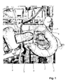
- FIG. 1 shows a detail of a diesel engine for industrial vehicle according to the present invention, which is a preferred embodiment of the present invention.
- the engine 1 is provided with an intake manifold 2, suitable to distribute the intake air to the combustion chambers, in the way known in the art.
- An intake line 3 brings the air sucked from the outside to the manifold.
- An exhaust gas recirculation line 4 brings a portion of the burnt gas withdrawn form the exhaust line to the intake line.
- An introduction module 5 of the type known, which may also function as mixer, may be included.
- the introduction point is downstream of the turbine on the intake line.
- the recirculation preferably takes place on the high pressure side, as defined above.
- Devices of the type known may also be used in order to allow the recirculation; for example it is possible to include a valve, for example a throttle valve placed upstream of the introduction point, as to induce a depression in correspondence of the introduction point of the recirculated gases.
- Reference 6 shows the control mechanism of such valve.
- pumps of various type may be used on the recirculation line, or throttling valves may be used on the exhaust line downstream of the withdrawal point of the gases to be recirculated, either before or after the turbine if the engine is turbocharged.
- a mobile diffuser of a variable geometry turbine may also be used in order to facilitate the recirculation.
- the intake line has a segment of pipe 7 placed between the introduction point of the recirculated gases and the intake manifold, preferably having a constant diameter and being long five times the internal diameter of its cross section.
- this section may be equal to that of the intake line upstream of the introduction point of the recirculated gases, or it may be duly enlarged.
- the passage section of the mixture of air and burnt gases has an enlargement 8 in correspondence of the input of the manifold 2, as known in the prior art.
- the segment 7 is preferably long from 5 to 10 times the internal diameter, more preferably from 7 and 8 times.
- the gas flow undergoes a change of direction in the segment, which has at least a bend, such that the curvature radius, in the section where it is minimum, preferably does not exceed 2 times the internal diameter of the section, more preferably it is between 0,5 and 2 times.
- the flow undergoes a change of direction between 90° and 270°, for example at about 180° as in the case shown.
- this input is at a longitudinal extremity of the intake manifold, as in certain engines known in the art, in order to distribute the gas flow among the cylinders.
- a cooler may be present on the intake line, in particular downstream of the compressor in a turbocharged engine (generally known as "aftercooler").
- the introduction point of the recirculated gases may be downstream of this cooler.
- the invention is particularly suitable, also in case the cooler is not present.
- Figure 1 shows an embodiment of the invention, which is particularly advantageous also in terms of the reduced dimensions of the structure.
- the axis of symmetry of the transversal section are tangent to a substantially flat curve, which defines the direction of the flow.
- Other alternative embodiments are possible according to the experience and the needs of the person skilled in the art.
Landscapes
- Engineering & Computer Science (AREA)
- Chemical & Material Sciences (AREA)
- Combustion & Propulsion (AREA)
- Mechanical Engineering (AREA)
- General Engineering & Computer Science (AREA)
- Physics & Mathematics (AREA)
- Thermal Sciences (AREA)
- Exhaust-Gas Circulating Devices (AREA)
Abstract
Description
- The present invention relates to an engine provided with exhaust gas recirculation, in particular a vehicle engine, more in particular a diesel engine for industrial vehicles. According to another embodiment, the invention relates to a turbocharged engine with exhaust gas recirculation on the high pressure side.
- Exhaust gas recirculation (or EGR) is a common practice in the field of internal combustion engines. According to this system a portion of the exhaust gases from the engine are recirculated upstream of the engine and then reintroduced into the combustion chambers with the intake air. This permits to lower the combustion flame temperature and leads to a reduced formation of nitrogen oxides, one of the main pollutants in internal combustion engine emissions.
- The recirculation may be carried out by means of a provided recirculation line which takes the exhaust gases downstream of the engine, for example from the exhaust gas manifold, and reintroduces them into the intake manifold. In case the engine is turbocharged, the recirculation may take place between a point upstream of the turbine on the exhaust line and a point downstream of the compressor on the intake line. In this case the recirculation is on the high pressure side.
- The recirculation line may be provided with different devices, for example a circulation compressor, if it is necessary to overcome a difference in pressure between the intake and the exhaust, a control valve, and a cooler in order to reduce the temperature of the recirculated gases.
- The direct introduction into the intake manifold is not satisfactory enough, because it does not guarantee a good mixing of the exhaust gases with the intake air. Consequently, the percentage of recirculated gas into the gas mixture going into the cylinders is not the same. This reduces the efficiency of the recirculation in terms of the abatement of the pollutants, worsens the combustion conditions and the engine performance, and makes the thrust of the cylinders unequal, causing different wear and corrosion conditions in the cylinders, due to the different quantity of corrosive components, usually present in the exhaust gases, which arrive to the cylinders. Various introduction system at the input of the intake line of the manifold have been proposed. For example
EP1580421 describes a module for the introduction of the recirculated gases through openings suitable to introduce the gas in a transverse direction with respect to the flow. The module is designed for being mounted at the input of the intake manifold and is able to considerably improve the mixing. However, the results are not yet satisfactory in terms of homogeneity of the distribution of the recirculated gases among the cylinders, and, in many applications, it has not always been possible to respect the targets in terms of pollutant emissions, given the stricter and stricter limits imposed by the law. It should be noted that the quantity of recirculated gases, according to these limits, has been growing more and more and the recirculated gases may represent considerable portions of the overall exhaust gases, often exceeding 30% and sometimes reaching 50%. - Therefore, it would be worthwhile to guarantee a higher uniformity of the distribution of the recirculated gases among the cylinders.
- The problems described above have been solved according to this invention by an internal-combustion engine, in particular a vehicle engine, equipped with a plurality of combustion chambers, an air intake line, an intake manifold suitable to distribute the air coming from said line to said combustion chambers, an exhaust line of the burnt gases, a recirculation line suitable to transfer a portion of the burnt gases from said exhaust line to said intake line, characterized in that said intake line has, between the introduction point of said burnt gases and the intake manifold, a segment of pipe long at least five times the internal diameter of its cross section. Preferably, this segment of pipe has a substantially constant section, more preferably a circular section. In case of non circular sections, the term "diameter" refers to the equivalent diameter.
- The invention relates also to a method for recirculating the burnt gases in an internal-combustion engine comprising the introduction of a portion of burnt gases into an intake line, the passage of a mixture of burnt gases and air in a segment of pipe long at least five times the internal diameter of its cross section being part of said intake line, and the subsequent introduction of said mixture in an intake manifold of said engine.
- The invention relates also to a vehicle, in particular an industrial vehicle, provided with the engine mentioned above.
- This invention refers in particular to what mentioned in the claims attached hereto.
- This invention will be now illustrated through a detailed description of preferred but non exclusive embodiments, furnished merely by way of example, with the aid of
figure 1 attached hereto which shows a detail of an engine, partly disassembled, for industrial vehicle according to the present invention. -
Figure 1 shows a detail of a diesel engine for industrial vehicle according to the present invention, which is a preferred embodiment of the present invention. The engine 1 is provided with an intake manifold 2, suitable to distribute the intake air to the combustion chambers, in the way known in the art. Anintake line 3 brings the air sucked from the outside to the manifold. An exhaust gas recirculation line 4 brings a portion of the burnt gas withdrawn form the exhaust line to the intake line. Anintroduction module 5 of the type known, which may also function as mixer, may be included. For example it is possible to include a distribution chamber around the intake line, said chamber being connected to the recirculation line and to the intake line by means of adequately distributed holes. If the engine is turbocharged, the introduction point is downstream of the turbine on the intake line. In this case, the recirculation preferably takes place on the high pressure side, as defined above. - Devices of the type known may also be used in order to allow the recirculation; for example it is possible to include a valve, for example a throttle valve placed upstream of the introduction point, as to induce a depression in correspondence of the introduction point of the recirculated gases.
Reference 6 shows the control mechanism of such valve. Otherwise pumps of various type may be used on the recirculation line, or throttling valves may be used on the exhaust line downstream of the withdrawal point of the gases to be recirculated, either before or after the turbine if the engine is turbocharged. A mobile diffuser of a variable geometry turbine may also be used in order to facilitate the recirculation. - It is also possible to include a cooler, in order to lower the temperature of the recirculated gases. These techniques are all known in the art, and do no need any further description.
- It has been found that, in order to obtain an optimal mixing, which guarantees a uniform distribution of the recirculated gases among the various combustion chambers, it is necessary that the intake line has a segment of
pipe 7 placed between the introduction point of the recirculated gases and the intake manifold, preferably having a constant diameter and being long five times the internal diameter of its cross section. According to an embodiment of the invention this section may be equal to that of the intake line upstream of the introduction point of the recirculated gases, or it may be duly enlarged. According to an embodiment of the invention, the passage section of the mixture of air and burnt gases has an enlargement 8 in correspondence of the input of the manifold 2, as known in the prior art. - The
segment 7 is preferably long from 5 to 10 times the internal diameter, more preferably from 7 and 8 times. - Preferably, the gas flow undergoes a change of direction in the segment, which has at least a bend, such that the curvature radius, in the section where it is minimum, preferably does not exceed 2 times the internal diameter of the section, more preferably it is between 0,5 and 2 times. According to a possible embodiment of the invention, the flow undergoes a change of direction between 90° and 270°, for example at about 180° as in the case shown. There may be a further change of direction in correspondence of the input of the manifold. According to a preferred embodiment, this input is at a longitudinal extremity of the intake manifold, as in certain engines known in the art, in order to distribute the gas flow among the cylinders.
- According to a particular embodiment of the invention, a cooler may be present on the intake line, in particular downstream of the compressor in a turbocharged engine (generally known as "aftercooler"). In this case, the introduction point of the recirculated gases may be downstream of this cooler. The invention is particularly suitable, also in case the cooler is not present.
-
Figure 1 shows an embodiment of the invention, which is particularly advantageous also in terms of the reduced dimensions of the structure. According to this embodiment, in the segment of pipe mentioned above the axis of symmetry of the transversal section are tangent to a substantially flat curve, which defines the direction of the flow. Other alternative embodiments are possible according to the experience and the needs of the person skilled in the art. - In comparison with solutions known in the art, even if they included a mixing module with the introduction of the recirculated gases close to or in correspondence the input of the intake manifold, it has been found that the present invention allows a better uniformity of the concentration of the recirculated gases in the various combustion chambers, with a variation lower than 1,5%, even in presence of a recirculation flow rate of 30% or more, a limit that is hardly reached by the engines of the type known. The possible improvement in terms of pollutant abatement in the burnt gases is considerable.
Claims (16)
- Internal-combustion engine, in particular a vehicle engine, equipped with a plurality of combustion chambers, an air intake line (3), an intake manifold (2) suitable to distribute the air coming from said line to said combustion chambers, an exhaust line for the burnt gases, a recirculation line (4) suitable to transfer a portion of the burnt gases from said exhaust line to said intake line, characterized in that said intake line features, between the introduction point of said burnt gases and the intake manifold, a segment of pipe (7) long at least five times the internal diameter of its cross section.
- Engine according to claim 1, characterized in that said segment of pipe is long from 5 to 10 times its internal diameter.
- Engine according to claim 2, characterized in that said segment of pipe is long from 7 to 8 times its internal diameter.
- Engine according to any of the previous claims, characterized in that said segment of pipe has at least a bend whose minimum curvature radius does not exceed 2 times the internal diameter of the section.
- Engine according to claim 4, characterized in that said segment of pipe induces a change of direction of between 90 and 270°.
- Turbocharged engine according to any of the previous claims, wherein the recirculation takes place on the high pressure side.
- Diesel engine according to any of the previous claims.
- Engine according to any of the previous claims, wherein no cooler is present on the intake line.
- Engine according to claim 6 wherein a cooler is present downstream of the turbocharged compressor and the introduction point of the recirculated gases is downstream of said cooler.
- Method for recirculating the burnt gases in an internal-combustion engine comprising the introduction of a portion of burnt gases in an intake line, the passage of a mixture of burnt gases and air in a segment of pipe long at least five times the internal diameter of its cross section being part of said intake line, and the subsequent introduction of said mixture in an intake manifold of said engine.
- Method according to claim 10, characterized in that said segment of pipe is long from 5 to 10 times its internal diameter.
- Method according to claim 11, characterized in that said segment of pipe is long from 7 to 8 times its internal diameter.
- Method according to any claim from 10 to 12, characterized in that said segment of pipe presents at least a bend whose minimum curvature radius does not exceed 2 times the internal diameter of the section.
- Method according to any claim from 10 to 13, characterized in that the gases, between the introduction point of the recirculated gases and the input of the intake manifold, are forced to a change of direction between 90 and 270°,
- Method according to any claim from 10 to 14, characterized in that the recirculated gases are introduced in the intake line downstream of a turbocharged compressor and of a possible cooler placed downstream of said compressor.
- Vehicle, in particular industrial vehicle provided with an engine according to any claim from 1 to 9.
Priority Applications (2)
| Application Number | Priority Date | Filing Date | Title |
|---|---|---|---|
| ES08425096T ES2435549T3 (en) | 2008-02-15 | 2008-02-15 | Engine with exhaust gas recirculation, method for recirculation and vehicle fitted with such engine |
| EP08425096.8A EP2090770B1 (en) | 2008-02-15 | 2008-02-15 | Engine with exhaust gas recirculation, method for recirculating and vehicle provided with such engine |
Applications Claiming Priority (1)
| Application Number | Priority Date | Filing Date | Title |
|---|---|---|---|
| EP08425096.8A EP2090770B1 (en) | 2008-02-15 | 2008-02-15 | Engine with exhaust gas recirculation, method for recirculating and vehicle provided with such engine |
Publications (2)
| Publication Number | Publication Date |
|---|---|
| EP2090770A1 true EP2090770A1 (en) | 2009-08-19 |
| EP2090770B1 EP2090770B1 (en) | 2013-08-21 |
Family
ID=39583921
Family Applications (1)
| Application Number | Title | Priority Date | Filing Date |
|---|---|---|---|
| EP08425096.8A Active EP2090770B1 (en) | 2008-02-15 | 2008-02-15 | Engine with exhaust gas recirculation, method for recirculating and vehicle provided with such engine |
Country Status (2)
| Country | Link |
|---|---|
| EP (1) | EP2090770B1 (en) |
| ES (1) | ES2435549T3 (en) |
Cited By (1)
| Publication number | Priority date | Publication date | Assignee | Title |
|---|---|---|---|---|
| EP2511509A1 (en) * | 2011-04-15 | 2012-10-17 | Caterpillar Motoren GmbH & Co. KG | Mixing pipe and internal combustion engine with a mixing pipe |
Citations (7)
| Publication number | Priority date | Publication date | Assignee | Title |
|---|---|---|---|---|
| DE2225852A1 (en) * | 1971-07-01 | 1973-01-18 | Ford Werke Ag | ARRANGEMENT FOR THE RECIRCULATION OF EXHAUST GASES FROM A COMBUSTION ENGINE |
| US4811697A (en) * | 1985-09-24 | 1989-03-14 | Yamaha Hatsudoki Kabushiki Kaisha | Induction system with E.G.R. |
| DE4320045A1 (en) | 1993-06-17 | 1994-07-28 | Daimler Benz Ag | Supercharged internal combustion engine |
| JP2002349355A (en) * | 2001-05-25 | 2002-12-04 | Nissan Motor Co Ltd | Exhaust gas recirculation system for internal combustion engine |
| WO2005057002A2 (en) * | 2003-12-11 | 2005-06-23 | Avl List Gmbh | Internal combustion engine |
| EP1580421A1 (en) | 2004-03-23 | 2005-09-28 | Iveco S.p.A. | Device for mixing exhaust gases to be recirculated to an engine with the intake air and a method for recirculating exhaust gases |
| US20070017490A1 (en) * | 2005-07-21 | 2007-01-25 | Nissan Motor Co., Ltd. | Internal combustion engine intake device |
-
2008
- 2008-02-15 EP EP08425096.8A patent/EP2090770B1/en active Active
- 2008-02-15 ES ES08425096T patent/ES2435549T3/en active Active
Patent Citations (7)
| Publication number | Priority date | Publication date | Assignee | Title |
|---|---|---|---|---|
| DE2225852A1 (en) * | 1971-07-01 | 1973-01-18 | Ford Werke Ag | ARRANGEMENT FOR THE RECIRCULATION OF EXHAUST GASES FROM A COMBUSTION ENGINE |
| US4811697A (en) * | 1985-09-24 | 1989-03-14 | Yamaha Hatsudoki Kabushiki Kaisha | Induction system with E.G.R. |
| DE4320045A1 (en) | 1993-06-17 | 1994-07-28 | Daimler Benz Ag | Supercharged internal combustion engine |
| JP2002349355A (en) * | 2001-05-25 | 2002-12-04 | Nissan Motor Co Ltd | Exhaust gas recirculation system for internal combustion engine |
| WO2005057002A2 (en) * | 2003-12-11 | 2005-06-23 | Avl List Gmbh | Internal combustion engine |
| EP1580421A1 (en) | 2004-03-23 | 2005-09-28 | Iveco S.p.A. | Device for mixing exhaust gases to be recirculated to an engine with the intake air and a method for recirculating exhaust gases |
| US20070017490A1 (en) * | 2005-07-21 | 2007-01-25 | Nissan Motor Co., Ltd. | Internal combustion engine intake device |
Cited By (1)
| Publication number | Priority date | Publication date | Assignee | Title |
|---|---|---|---|---|
| EP2511509A1 (en) * | 2011-04-15 | 2012-10-17 | Caterpillar Motoren GmbH & Co. KG | Mixing pipe and internal combustion engine with a mixing pipe |
Also Published As
| Publication number | Publication date |
|---|---|
| EP2090770B1 (en) | 2013-08-21 |
| ES2435549T3 (en) | 2013-12-20 |
Similar Documents
| Publication | Publication Date | Title |
|---|---|---|
| US7568340B2 (en) | Exhaust gas recirculation mixer | |
| US9032940B2 (en) | Systems and methods for dedicated exhaust gas recirculation and control | |
| US10082110B2 (en) | Mixer for dedicated exhaust gas recirculation systems | |
| US7444815B2 (en) | EGR system for high EGR rates | |
| EP2320051B1 (en) | Emission control system for an engine having a two-stage turbocharger | |
| US11015553B2 (en) | Exhaust gas recirculation and control with twin scroll turbines | |
| US9518519B2 (en) | Transient control of exhaust gas recirculation systems through mixer control valves | |
| KR20080095843A (en) | Mixing unit for low pressure EBR condensate entering the compressor | |
| US9835116B2 (en) | Internal combustion engine for a motor vehicle, and method for operating such an internal combustion engine | |
| US6439212B1 (en) | Bypass venturi assembly and elbow with turning vane for an exhaust gas recirculation system | |
| EP1957783B1 (en) | Exhaust gas recirculation mixer for a turbo-charged internal combustion engine | |
| US10215086B2 (en) | Exhaust gas recirculation system for an internal combustion engine and method for operating such an exhaust gas recirculation system | |
| EP2322787A2 (en) | Exhaust gas recirculation system | |
| EP2236804A1 (en) | Gas mixing device particularly for internal-combustion engines equipped with exhaust gas recirculation system | |
| EP2090770B1 (en) | Engine with exhaust gas recirculation, method for recirculating and vehicle provided with such engine | |
| US7343908B2 (en) | EGR system having EGR valve with purge air chamber | |
| US9695779B2 (en) | Exhaust gas mixing system | |
| US20090139500A1 (en) | Exhaust gas recirculation system | |
| US20170122233A1 (en) | Exhaust Gas Recirculation System | |
| EP1674710A1 (en) | Method for recirculating exhaust gases in a turbocharged engine and the relative turbocharged engine | |
| EP1580421A1 (en) | Device for mixing exhaust gases to be recirculated to an engine with the intake air and a method for recirculating exhaust gases | |
| CN104863695B (en) | Apparatus, method and system for optimizing engine performance for high torque operation | |
| CN109488489A (en) | Thermal exhaust recirculating system |
Legal Events
| Date | Code | Title | Description |
|---|---|---|---|
| PUAI | Public reference made under article 153(3) epc to a published international application that has entered the european phase |
Free format text: ORIGINAL CODE: 0009012 |
|
| AK | Designated contracting states |
Kind code of ref document: A1 Designated state(s): AT BE BG CH CY CZ DE DK EE ES FI FR GB GR HR HU IE IS IT LI LT LU LV MC MT NL NO PL PT RO SE SI SK TR |
|
| AX | Request for extension of the european patent |
Extension state: AL BA MK RS |
|
| 17P | Request for examination filed |
Effective date: 20100217 |
|
| AKX | Designation fees paid |
Designated state(s): AT BE BG CH CY CZ DE DK EE ES FI FR GB GR HR HU IE IS IT LI LT LU LV MC MT NL NO PL PT RO SE SI SK TR |
|
| 17Q | First examination report despatched |
Effective date: 20110920 |
|
| RAP1 | Party data changed (applicant data changed or rights of an application transferred) |
Owner name: FPT INDUSTRIAL S.P.A. |
|
| GRAP | Despatch of communication of intention to grant a patent |
Free format text: ORIGINAL CODE: EPIDOSNIGR1 |
|
| GRAS | Grant fee paid |
Free format text: ORIGINAL CODE: EPIDOSNIGR3 |
|
| GRAA | (expected) grant |
Free format text: ORIGINAL CODE: 0009210 |
|
| AK | Designated contracting states |
Kind code of ref document: B1 Designated state(s): AT BE BG CH CY CZ DE DK EE ES FI FR GB GR HR HU IE IS IT LI LT LU LV MC MT NL NO PL PT RO SE SI SK TR |
|
| REG | Reference to a national code |
Ref country code: GB Ref legal event code: FG4D |
|
| REG | Reference to a national code |
Ref country code: CH Ref legal event code: EP |
|
| REG | Reference to a national code |
Ref country code: AT Ref legal event code: REF Ref document number: 628256 Country of ref document: AT Kind code of ref document: T Effective date: 20130915 |
|
| REG | Reference to a national code |
Ref country code: IE Ref legal event code: FG4D |
|
| REG | Reference to a national code |
Ref country code: DE Ref legal event code: R096 Ref document number: 602008026936 Country of ref document: DE Effective date: 20131017 |
|
| REG | Reference to a national code |
Ref country code: CH Ref legal event code: NV Representative=s name: N&G PATENT SERVICES SA, CH |
|
| REG | Reference to a national code |
Ref country code: SE Ref legal event code: TRGR |
|
| REG | Reference to a national code |
Ref country code: NL Ref legal event code: T3 |
|
| REG | Reference to a national code |
Ref country code: ES Ref legal event code: FG2A Ref document number: 2435549 Country of ref document: ES Kind code of ref document: T3 Effective date: 20131220 |
|
| REG | Reference to a national code |
Ref country code: AT Ref legal event code: MK05 Ref document number: 628256 Country of ref document: AT Kind code of ref document: T Effective date: 20130821 |
|
| REG | Reference to a national code |
Ref country code: LT Ref legal event code: MG4D |
|
| PG25 | Lapsed in a contracting state [announced via postgrant information from national office to epo] |
Ref country code: AT Free format text: LAPSE BECAUSE OF FAILURE TO SUBMIT A TRANSLATION OF THE DESCRIPTION OR TO PAY THE FEE WITHIN THE PRESCRIBED TIME-LIMIT Effective date: 20130821 Ref country code: PT Free format text: LAPSE BECAUSE OF FAILURE TO SUBMIT A TRANSLATION OF THE DESCRIPTION OR TO PAY THE FEE WITHIN THE PRESCRIBED TIME-LIMIT Effective date: 20131223 Ref country code: LT Free format text: LAPSE BECAUSE OF FAILURE TO SUBMIT A TRANSLATION OF THE DESCRIPTION OR TO PAY THE FEE WITHIN THE PRESCRIBED TIME-LIMIT Effective date: 20130821 Ref country code: CY Free format text: LAPSE BECAUSE OF FAILURE TO SUBMIT A TRANSLATION OF THE DESCRIPTION OR TO PAY THE FEE WITHIN THE PRESCRIBED TIME-LIMIT Effective date: 20130807 Ref country code: IS Free format text: LAPSE BECAUSE OF FAILURE TO SUBMIT A TRANSLATION OF THE DESCRIPTION OR TO PAY THE FEE WITHIN THE PRESCRIBED TIME-LIMIT Effective date: 20131221 Ref country code: NO Free format text: LAPSE BECAUSE OF FAILURE TO SUBMIT A TRANSLATION OF THE DESCRIPTION OR TO PAY THE FEE WITHIN THE PRESCRIBED TIME-LIMIT Effective date: 20131121 Ref country code: HR Free format text: LAPSE BECAUSE OF FAILURE TO SUBMIT A TRANSLATION OF THE DESCRIPTION OR TO PAY THE FEE WITHIN THE PRESCRIBED TIME-LIMIT Effective date: 20130821 |
|
| PG25 | Lapsed in a contracting state [announced via postgrant information from national office to epo] |
Ref country code: GR Free format text: LAPSE BECAUSE OF FAILURE TO SUBMIT A TRANSLATION OF THE DESCRIPTION OR TO PAY THE FEE WITHIN THE PRESCRIBED TIME-LIMIT Effective date: 20131122 Ref country code: BE Free format text: LAPSE BECAUSE OF FAILURE TO SUBMIT A TRANSLATION OF THE DESCRIPTION OR TO PAY THE FEE WITHIN THE PRESCRIBED TIME-LIMIT Effective date: 20130821 Ref country code: PL Free format text: LAPSE BECAUSE OF FAILURE TO SUBMIT A TRANSLATION OF THE DESCRIPTION OR TO PAY THE FEE WITHIN THE PRESCRIBED TIME-LIMIT Effective date: 20130821 Ref country code: SI Free format text: LAPSE BECAUSE OF FAILURE TO SUBMIT A TRANSLATION OF THE DESCRIPTION OR TO PAY THE FEE WITHIN THE PRESCRIBED TIME-LIMIT Effective date: 20130821 Ref country code: LV Free format text: LAPSE BECAUSE OF FAILURE TO SUBMIT A TRANSLATION OF THE DESCRIPTION OR TO PAY THE FEE WITHIN THE PRESCRIBED TIME-LIMIT Effective date: 20130821 Ref country code: FI Free format text: LAPSE BECAUSE OF FAILURE TO SUBMIT A TRANSLATION OF THE DESCRIPTION OR TO PAY THE FEE WITHIN THE PRESCRIBED TIME-LIMIT Effective date: 20130821 |
|
| PG25 | Lapsed in a contracting state [announced via postgrant information from national office to epo] |
Ref country code: CY Free format text: LAPSE BECAUSE OF FAILURE TO SUBMIT A TRANSLATION OF THE DESCRIPTION OR TO PAY THE FEE WITHIN THE PRESCRIBED TIME-LIMIT Effective date: 20130821 |
|
| PG25 | Lapsed in a contracting state [announced via postgrant information from national office to epo] |
Ref country code: RO Free format text: LAPSE BECAUSE OF FAILURE TO SUBMIT A TRANSLATION OF THE DESCRIPTION OR TO PAY THE FEE WITHIN THE PRESCRIBED TIME-LIMIT Effective date: 20130821 Ref country code: CZ Free format text: LAPSE BECAUSE OF FAILURE TO SUBMIT A TRANSLATION OF THE DESCRIPTION OR TO PAY THE FEE WITHIN THE PRESCRIBED TIME-LIMIT Effective date: 20130821 Ref country code: DK Free format text: LAPSE BECAUSE OF FAILURE TO SUBMIT A TRANSLATION OF THE DESCRIPTION OR TO PAY THE FEE WITHIN THE PRESCRIBED TIME-LIMIT Effective date: 20130821 Ref country code: EE Free format text: LAPSE BECAUSE OF FAILURE TO SUBMIT A TRANSLATION OF THE DESCRIPTION OR TO PAY THE FEE WITHIN THE PRESCRIBED TIME-LIMIT Effective date: 20130821 Ref country code: SK Free format text: LAPSE BECAUSE OF FAILURE TO SUBMIT A TRANSLATION OF THE DESCRIPTION OR TO PAY THE FEE WITHIN THE PRESCRIBED TIME-LIMIT Effective date: 20130821 |
|
| PLBE | No opposition filed within time limit |
Free format text: ORIGINAL CODE: 0009261 |
|
| STAA | Information on the status of an ep patent application or granted ep patent |
Free format text: STATUS: NO OPPOSITION FILED WITHIN TIME LIMIT |
|
| 26N | No opposition filed |
Effective date: 20140522 |
|
| REG | Reference to a national code |
Ref country code: DE Ref legal event code: R097 Ref document number: 602008026936 Country of ref document: DE Effective date: 20140522 |
|
| PG25 | Lapsed in a contracting state [announced via postgrant information from national office to epo] |
Ref country code: MC Free format text: LAPSE BECAUSE OF FAILURE TO SUBMIT A TRANSLATION OF THE DESCRIPTION OR TO PAY THE FEE WITHIN THE PRESCRIBED TIME-LIMIT Effective date: 20130821 Ref country code: LU Free format text: LAPSE BECAUSE OF FAILURE TO SUBMIT A TRANSLATION OF THE DESCRIPTION OR TO PAY THE FEE WITHIN THE PRESCRIBED TIME-LIMIT Effective date: 20140215 |
|
| REG | Reference to a national code |
Ref country code: IE Ref legal event code: MM4A |
|
| PG25 | Lapsed in a contracting state [announced via postgrant information from national office to epo] |
Ref country code: IE Free format text: LAPSE BECAUSE OF NON-PAYMENT OF DUE FEES Effective date: 20140215 |
|
| REG | Reference to a national code |
Ref country code: FR Ref legal event code: PLFP Year of fee payment: 9 |
|
| PG25 | Lapsed in a contracting state [announced via postgrant information from national office to epo] |
Ref country code: MT Free format text: LAPSE BECAUSE OF FAILURE TO SUBMIT A TRANSLATION OF THE DESCRIPTION OR TO PAY THE FEE WITHIN THE PRESCRIBED TIME-LIMIT Effective date: 20130821 |
|
| PG25 | Lapsed in a contracting state [announced via postgrant information from national office to epo] |
Ref country code: BG Free format text: LAPSE BECAUSE OF FAILURE TO SUBMIT A TRANSLATION OF THE DESCRIPTION OR TO PAY THE FEE WITHIN THE PRESCRIBED TIME-LIMIT Effective date: 20130821 |
|
| PG25 | Lapsed in a contracting state [announced via postgrant information from national office to epo] |
Ref country code: TR Free format text: LAPSE BECAUSE OF FAILURE TO SUBMIT A TRANSLATION OF THE DESCRIPTION OR TO PAY THE FEE WITHIN THE PRESCRIBED TIME-LIMIT Effective date: 20130821 Ref country code: HU Free format text: LAPSE BECAUSE OF FAILURE TO SUBMIT A TRANSLATION OF THE DESCRIPTION OR TO PAY THE FEE WITHIN THE PRESCRIBED TIME-LIMIT; INVALID AB INITIO Effective date: 20080215 |
|
| REG | Reference to a national code |
Ref country code: FR Ref legal event code: PLFP Year of fee payment: 10 |
|
| REG | Reference to a national code |
Ref country code: FR Ref legal event code: PLFP Year of fee payment: 11 |
|
| P01 | Opt-out of the competence of the unified patent court (upc) registered |
Effective date: 20230519 |
|
| REG | Reference to a national code |
Ref country code: CH Ref legal event code: U11 Free format text: ST27 STATUS EVENT CODE: U-0-0-U10-U11 (AS PROVIDED BY THE NATIONAL OFFICE) Effective date: 20260301 |
|
| PGFP | Annual fee paid to national office [announced via postgrant information from national office to epo] |
Ref country code: NL Payment date: 20260220 Year of fee payment: 19 |
|
| PGFP | Annual fee paid to national office [announced via postgrant information from national office to epo] |
Ref country code: SE Payment date: 20260223 Year of fee payment: 19 |
|
| PGFP | Annual fee paid to national office [announced via postgrant information from national office to epo] |
Ref country code: GB Payment date: 20260223 Year of fee payment: 19 |
|
| PGFP | Annual fee paid to national office [announced via postgrant information from national office to epo] |
Ref country code: ES Payment date: 20260317 Year of fee payment: 19 |
|
| PGFP | Annual fee paid to national office [announced via postgrant information from national office to epo] |
Ref country code: DE Payment date: 20260220 Year of fee payment: 19 |
|
| PGFP | Annual fee paid to national office [announced via postgrant information from national office to epo] |
Ref country code: IT Payment date: 20260209 Year of fee payment: 19 |
|
| PGFP | Annual fee paid to national office [announced via postgrant information from national office to epo] |
Ref country code: FR Payment date: 20260227 Year of fee payment: 19 |
|
| PGFP | Annual fee paid to national office [announced via postgrant information from national office to epo] |
Ref country code: CH Payment date: 20260301 Year of fee payment: 19 |