EP2090442A1 - Fahrzeugluftreifen - Google Patents
Fahrzeugluftreifen Download PDFInfo
- Publication number
- EP2090442A1 EP2090442A1 EP09151165A EP09151165A EP2090442A1 EP 2090442 A1 EP2090442 A1 EP 2090442A1 EP 09151165 A EP09151165 A EP 09151165A EP 09151165 A EP09151165 A EP 09151165A EP 2090442 A1 EP2090442 A1 EP 2090442A1
- Authority
- EP
- European Patent Office
- Prior art keywords
- block
- snow
- pneumatic vehicle
- vehicle tire
- tire according
- Prior art date
- Legal status (The legal status is an assumption and is not a legal conclusion. Google has not performed a legal analysis and makes no representation as to the accuracy of the status listed.)
- Granted
Links
- 238000005096 rolling process Methods 0.000 claims description 3
- 230000007423 decrease Effects 0.000 claims description 2
- 230000015572 biosynthetic process Effects 0.000 abstract 1
- 230000000694 effects Effects 0.000 description 3
- 230000002411 adverse Effects 0.000 description 1
Images
Classifications
-
- B—PERFORMING OPERATIONS; TRANSPORTING
- B60—VEHICLES IN GENERAL
- B60C—VEHICLE TYRES; TYRE INFLATION; TYRE CHANGING; CONNECTING VALVES TO INFLATABLE ELASTIC BODIES IN GENERAL; DEVICES OR ARRANGEMENTS RELATED TO TYRES
- B60C11/00—Tyre tread bands; Tread patterns; Anti-skid inserts
- B60C11/03—Tread patterns
- B60C11/0302—Tread patterns directional pattern, i.e. with main rolling direction
-
- B—PERFORMING OPERATIONS; TRANSPORTING
- B60—VEHICLES IN GENERAL
- B60C—VEHICLE TYRES; TYRE INFLATION; TYRE CHANGING; CONNECTING VALVES TO INFLATABLE ELASTIC BODIES IN GENERAL; DEVICES OR ARRANGEMENTS RELATED TO TYRES
- B60C11/00—Tyre tread bands; Tread patterns; Anti-skid inserts
- B60C11/03—Tread patterns
- B60C11/12—Tread patterns characterised by the use of narrow slits or incisions, e.g. sipes
-
- B—PERFORMING OPERATIONS; TRANSPORTING
- B60—VEHICLES IN GENERAL
- B60C—VEHICLE TYRES; TYRE INFLATION; TYRE CHANGING; CONNECTING VALVES TO INFLATABLE ELASTIC BODIES IN GENERAL; DEVICES OR ARRANGEMENTS RELATED TO TYRES
- B60C11/00—Tyre tread bands; Tread patterns; Anti-skid inserts
- B60C11/03—Tread patterns
- B60C11/13—Tread patterns characterised by the groove cross-section, e.g. for buttressing or preventing stone-trapping
- B60C11/1376—Three dimensional block surfaces departing from the enveloping tread contour
- B60C11/1392—Three dimensional block surfaces departing from the enveloping tread contour with chamfered block edges
-
- B—PERFORMING OPERATIONS; TRANSPORTING
- B60—VEHICLES IN GENERAL
- B60C—VEHICLE TYRES; TYRE INFLATION; TYRE CHANGING; CONNECTING VALVES TO INFLATABLE ELASTIC BODIES IN GENERAL; DEVICES OR ARRANGEMENTS RELATED TO TYRES
- B60C11/00—Tyre tread bands; Tread patterns; Anti-skid inserts
- B60C11/03—Tread patterns
- B60C2011/0337—Tread patterns characterised by particular design features of the pattern
- B60C2011/0339—Grooves
- B60C2011/0381—Blind or isolated grooves
-
- B—PERFORMING OPERATIONS; TRANSPORTING
- B60—VEHICLES IN GENERAL
- B60C—VEHICLE TYRES; TYRE INFLATION; TYRE CHANGING; CONNECTING VALVES TO INFLATABLE ELASTIC BODIES IN GENERAL; DEVICES OR ARRANGEMENTS RELATED TO TYRES
- B60C11/00—Tyre tread bands; Tread patterns; Anti-skid inserts
- B60C11/03—Tread patterns
- B60C11/12—Tread patterns characterised by the use of narrow slits or incisions, e.g. sipes
- B60C11/1204—Tread patterns characterised by the use of narrow slits or incisions, e.g. sipes with special shape of the sipe
- B60C2011/1213—Tread patterns characterised by the use of narrow slits or incisions, e.g. sipes with special shape of the sipe sinusoidal or zigzag at the tread surface
Definitions
- the invention relates to a pneumatic vehicle tire for use in wintry driving conditions, with a tread, which is executed directionally bound and profile elements, such as tread blocks and tread ribs, which are separated by circumferentially circumferential grooves, with tread blocks are provided whose limited by a circumferential groove block edges each divided by a projecting into the block snow bag into two flank sections.
- each block has at its limited circumferential grooves block chamfers, which extend along the respective block edge in the circumferential direction and converge pointedly towards Blockeck.
- Each block preferably has two such chamfers tapering at diagonally opposite corners.
- the invention has for its object in a tire of the type mentioned the effect of the snow bags and thus significantly improve the traction of the tire on snow.
- the object is achieved according to the invention in that the block edge portion which, based on the rolling direction of the tire, is in front of the snow bag, chamfered to form an inclined surface which is inclined from the block top in the direction of circumferential groove.
- the inclined surfaces are able to transport more snow into the snow pockets as the tire rolls on snowy ground and to help compact the snow in the snow pockets.
- the "snow teeth" formed in the snow pockets in this way allow more traction of the tire on a snowy ground.
- the inclined surfaces it is advantageous if they are inclined relative to the radial direction at an angle of 30 ° to 60 °.
- each inclined surface is located at a distance from the block top, which is 20% to 80% of the depth of the circumferential groove and located on the block top boundary edge of each inclined surface between the block inside end of the snow bag and half of the extension of the snow bag is positioned.
- the effect of the inclined surfaces can be effectively supported by providing a row of blocks opposite the block row provided with the snow pockets, with the corner areas of the blocks of this block row lying opposite the inclined faces each having a half-blade-like shape Recess are provided.
- these recesses In order for these recesses to be particularly effective in conveying snow from the circumferential groove into the snow pockets, their greatest depth should be between 50% and 80% of the depth of the circumferential groove and the most deep point located at the block corner. In this context, the circumferential extent of the recess is important, the recess should extend so far that its end is in the area opposite the snow bag.
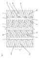
- Fig. 1 shows a portion of a tread, which are particularly suitable and intended for winter tires of passenger cars.
- running treads are designed directionally bound so that a tire with such a tread is to be mounted on the vehicle such that a certain unwinding direction, the in Fig. 1 to Fig. 3 indicated by the arrow R, is complied with.
- the in Fig. 1 Tread shown by way of example has one along the tire equator which passes through the line AA is marked, circumferential circumferential groove 1 in the circumferential direction.
- On both sides of the circumferential groove 1 extends in each case a row of blocks 2, which is separated by a respective circumferential groove 3 circumferential in the circumferential direction of a shoulder block row 4.
- the blocks 2a in the block row 2 and the shoulder blocks 4a in the shoulder block rows 4 are separated from each other by transverse grooves 5a, 5b, which, viewed over the entire width of the tread, are swept in the direction of the tire equator AA, so that the course of the transverse grooves 5a , 5b shows the directionality.
- the transverse grooves 5b in the embodiment shown enclose an angle of the order of 45 ° with the circumferential direction, the transverse grooves 5b extend substantially in the tread direction
- the blocks 2a in the two middle rows of blocks 2 are each provided with a number of wavy or zig-zag shaped incisions 6 in plan view which extend substantially in the tread transverse direction.
- the shoulder blocks 4a in the shoulder block rows 4 are each provided with two approximately zigzag-shaped cuts 7, which extend parallel to the transverse grooves 5a.
- the limited by the circumferential groove 3 block edges 9 of the shoulder blocks 4a are interrupted in their middle section in each case by a projecting into the block 4a snow bag 8, whereby two flank sections 9a, 9b are formed.
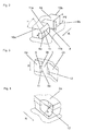
- the snow bags 8 are designed in the manner of short blind grooves, as in Fig. 1 and Fig. 2 is shown, can reach 3 to the bottom of the circumferential grooves.
- the snow pockets 8 are made such that their depth t, viewed from the block surface, is at least 50% of the depth PT of the circumferential grooves 3.
- the snow bags 8 extend with a substantially constant width of 4 mm to 6 mm in the tread strip transverse direction.
- the snow bags 8 can also be slightly narrower in the direction of the block interior.
- each block 4a an incoming block edge 10a - this occurs when rolling the tire first in the ground - and an expiring block edge 10b.
- an inclined surface 11 is formed, which is designed such that it is inclined at an angle ⁇ in the order of 30 ° to 60 ° to the radial direction that its radially inner boundary edge 11 a at a distance a from 20% to 80 % of the depth PT of the circumferential groove 3 is located and that its located on the block top second boundary edge 11b is positioned at least at 50% of the extension of the snow bag 8 in the block 4a.
- the boundary edge 11b may also be located on the block inside end of the snow bag 8.
- the inclined surface 11 is rectangular and its boundary edges 11a, 11b are parallel to each other and parallel to the circumferential groove. 3
- Fig. 3 shows a shoulder block 4a and the opposite block 2a of a block row 2 and a portion of the running between the blocks 2a, 4a circumferential groove 3.
- block 4a are analogous to Fig. 1 a snow bag 8 and an inclined surface 11 is formed.
- the corner of the block 2a opposite the inclined surface 11 on the block 4a is rounded off like a half-blade.
- This rounded recess 12 has its greatest depth b at the block corner, where b is between 50% and 80% of the depth PT.
- the recess 12 extends at least to the snow bag 8, in particular to the end of the snow bag 8, possibly also slightly beyond this.
- the width c of the recess 12 is up to 5 mm at the block corner and decreases to zero at the end of the recess 12, opposite the snow bag 8.
- the invention is not limited to the illustrated embodiments. It is possible to arrange snow pockets and inclined surfaces in middle block rows. In a running strip according to the invention, block rows can also be provided in combination with profile ribs.
Landscapes
- Engineering & Computer Science (AREA)
- Mechanical Engineering (AREA)
- Tires In General (AREA)
Abstract
Description
- Die Erfindung betrifft einen Fahrzeugluftreifen für den Einsatz unter winterlichen Fahrbedingungen, mit einem Laufstreifen, welcher laufrichtungsgebunden ausgeführt ist und Profilelemente, wie Profilblöcke und Profilrippen aufweist, die durch in Umfangsrichtung umlaufende Umfangsnuten voneinander getrennt sind, wobei Profilblöcke vorgesehen sind, deren von einer Umfangsnut begrenzte Blockflanken jeweils durch eine in den Block hineinragende Schneetasche in zwei Flankenabschnitte geteilt ist.
- Es ist bekannt, in Laufstreifen von Winterreifen für Personenkraftwagen Schneetaschen - dies sind kurze, sacknutartige Einbuchtungen in den Profilblöcken - vorzusehen, welche die Aufgabe haben, Schnee am Durchrutschen in der benachbarten Umfangsnut zu hindern, um Traktion aufzubauen.
- Aus der
WO 03/013881 A - Der Erfindung liegt die Aufgabe zugrunde bei einem Reifen der eingangs genannten Art die Wirkung der Schneetaschen und damit die Traktion des Reifens auf Schnee signifikant zu verbessern.
- Gelöst wird die gestellte Aufgabe erfindungsgemäß dadurch, dass der Blockflankenabschnitt, welcher sich, bezogen auf die Abrollrichtung des Reifens, vor der Schneetasche befindet, unter Bildung einer Schrägfläche, welche von der Blockoberseite in Richtung Umfangsnut geneigt ist, angefast ist.
- Die Schrägflächen sind in der Lage, beim Abrollen des Reifens auf schneeigem Untergrund vermehrt Schnee in die Schneetaschen zu befördern und ein Verdichten des Schnees in den Schneetaschen zu unterstützen. Die auf diese Weise in den Schneetaschen gebildeten "Schneeverzahnungen" ermöglichen mehr Traktion des Reifens auf schneeigem Untergrund.
- Für eine besonders effektive Wirkung der Schrägflächen ist es von Vorteil, wenn diese gegenüber der radialen Richtung unter einem Winkel von 30° bis 60° geneigt verlaufen.
- Auch der Größe der Schrägflächen kommt in diesem Zusammenhang eine gewisse Bedeutung zu, wobei es von Vorteil ist, wenn sich die radial innere Begrenzungskante jeder Schrägfläche in einem Abstand von der Blockoberseite befindet, welcher 20% bis 80% der Tiefe der Umfangsnut beträgt und wenn die an der Blockoberseite befindliche Begrenzungskante jeder Schrägfläche zwischen dem blockinnenseitigen Ende der Schneetasche und der Hälfte der Erstreckung der Schneetasche positioniert ist.
- Der Effekt der Schrägflächen, gezielt Schnee in die Schneetaschen zu befördern, kann dadurch wirkungsvoll unterstützt werden, dass vorgesehen ist, gegenüber der mit den Schneetaschen versehenen Blockreihe eine weitere Blockreihe anzuordnen, wobei die den Schrägflächen gegenüber liegenden Eckbereiche der Blöcke dieser Blockreihe jeweils mit einer halbschaufelartigen Ausnehmung versehen sind.
- Damit diese Ausnehmungen besonders wirkungsvoll dazu beitragen, Schnee aus der Umfangsnut in die Schneetaschen zu befördern, sollte ihre größte Tiefe zwischen 50% und 80% der Tiefe der Umfangsnut betragen und die Stelle mit der größten Tiefe an der Blockecke positioniert sein. In diesem Zusammenhang kommt auch der Umfangserstreckung der Ausnehmung Bedeutung zu, die Ausnehmung sollte sich soweit erstrecken, dass sich ihr Ende im Bereich gegenüber der Schneetasche befindet.
- Ein unerwünschtes Verfangen von Schnee in der Ausnehmung wird dadurch verhindert, dass die Ausnehmung über ihre Erstreckung entlang der Umfangsnut derart ausgeführt wird, dass ihre Breite an der Blockecke maximal 5 mm beträgt und bis zum Ende der Ausnehmung gegenüber der Schneetasche auf bis zu 0 mm abgenommen hat.
- Weitere Merkmale, Vorteile und Einzelheiten der Erfindung werden nun anhand der Zeichnung, die schematisch Ausführungsbeispiele darstellt, näher beschrieben. Dabei zeigen
-
Fig. 1 eine Draufsicht auf einen Abschnitt eines Laufstreifens eines Fahrzeugluftreifens, -
Fig. 2 eine Schrägansicht eines Blockes ausFig. 1 , -
Fig. 3 eine Draufsicht auf zwei Profilblöcke eines Laufstreifens mit einer weiteren Ausführungsform der Erfindung und -
Fig. 4 eine Schrägansicht des einen Blockes ausFig. 3 . -
Fig. 1 zeigt einen Abschnitt eines Laufstreifens, der insbesondere für Winterreifen von Personenkraftwagen geeignet und vorgesehen sind. Erfindungsgemäß ausgeführte Laufstreifen sind laufrichtungsgebunden gestaltet, sodass ein Reifen mit einem solchen Laufstreifen derart am Fahrzeug zu montieren ist, dass eine bestimmte Abrollrichtung, die inFig. 1 bis Fig. 3 mit dem Pfeil R angedeutet ist, eingehalten ist. Der inFig. 1 beispielhaft gezeigte Laufstreifen weist eine entlang des Reifenäquators, welcher durch die Linie A-A gekennzeichnet ist, in Umfangsrichtung umlaufende breite Umfangsnut 1 auf. Beidseitig der Umfangsnut 1 verläuft jeweils eine Blockreihe 2, die durch je eine weitere, in Umfangsrichtung umlaufende Umfangsnut 3 von einer Schulterblockreihe 4 getrennt ist. Die Blöcke 2a in der Blockreihe 2 und die Schulterblöcke 4a in den Schulterblockreihen 4 sind voneinander durch Quernuten 5a, 5b getrennt, welche, über die gesamte Breite des Laufstreifens betrachtet, in Richtung zum Reifenäquator A-A gepfeilt verlaufen, sodass sich durch den Verlauf der Quernuten 5a, 5b die Laufrichtungsgebundenheit ergibt. Die Quernuten 5b schließen bei der gezeigten Ausführungsform mit der Umfangsrichtung einen Winkel in der Größenordnung von 45° ein, die Quernuten 5b verlaufen im Wesentlichen in Laufstreifenrichtung - Die Blöcke 2a in den beiden mittleren Blockreihen 2 sind jeweils mit einer Anzahl von in Draufsicht wellen- oder zick-zack-förmig verlaufenden Einschnitten 6 versehen, die sich im Wesentlichen in Laufstreifenquerrichtung erstrecken. Die Schulterblöcke 4a in den Schulterblockreihen 4 sind jeweils mit zwei etwa zick-zack-förmigen Einschnitten 7 versehen, welche sich parallel zu den Quernuten 5a erstrecken.
- Die von der Umfangsnut 3 begrenzten Blockflanken 9 der Schulterblöcke 4a sind in ihrem mittleren Abschnitt jeweils von einer in den Block 4a hineinragenden Schneetasche 8 unterbrochen, wodurch zwei Flankenabschnitte 9a, 9b gebildet werden. Die Schneetaschen 8 sind in der Art von kurzen Sacknuten ausgeführt, die wie in
Fig. 1 undFig. 2 gezeigt ist, bis zum Grund der Umfangsnuten 3 reichen können. Die Schneetaschen 8 werden derart ausgeführt, dass ihre Tiefe t, von der Blockoberfläche aus betrachtet, mindestens 50% der Tiefe PT der Umfangsnuten 3 beträgt. Die Schneetaschen 8 erstrecken sich mit einer im Wesentlichen konstanten Breite von 4 mm bis 6 mm in Lauftstreifenquerrichtung. Die Schneetaschen 8 können auch in Richtung Blockinneres geringfügig schmäler werden. Die Erstreckung der Schneetaschen 8 in den jeweiligen Block 4a beträgt zwischen 4 mm und 8 mm. Durch die laufrichtungsgebundene Ausführung des Laufstreifens weist jeder Block 4a eine einlaufende Blockkante 10a - diese tritt beim Abrollen des Reifens zuerst in den Untergrund ein - und eine auslaufende Blockkante 10b auf. Gemäß der Erfindung ist der an die einlaufende Blockkante 10a anschließende Abschnitt 9a der Blockflanke 9 an der Blockoberseite angefast. Dadurch wird eine Schrägfläche 11 gebildet, die derart ausgeführt wird, dass sie unter einem Winkel α in der Größenordnung von 30 ° bis 60 ° zur radialen Richtung geneigt ist, dass ihre radial innere Begrenzungskante 11 a sich in einem Abstand a von 20% bis 80% der Tiefe PT der Umfangsnut 3 befindet und dass ihre an der Blockoberseite befindliche zweite Begrenzungskante 11b zumindest bei 50% der Erstreckung der Schneetasche 8 in den Block 4a positioniert ist. Die Begrenzungskante 11b kann sich auch am blockinnenseitigen Ende der Schneetasche 8 befinden. Gemäß einer bevorzugten Ausführung ist die Schrägfläche 11 rechteckig und ihre Begrenzungskanten 11a, 11b verlaufen parallel zueinander und parallel zur Umfangsnut 3. -
Fig. 3 zeigt einen Schulterblock 4a und den diesem gegenüber liegenden Block 2a einer Blockreihe 2 sowie einen Abschnitt der zwischen den Blöcken 2a, 4a verlaufenden Umfangsnut 3. Im Block 4a sind analog zuFig. 1 eine Schneetasche 8 und eine Schrägfläche 11 ausgebildet. Die der Schrägfläche 11 am Block 4a gegenüberliegende Ecke des Blockes 2a ist halbschaufelartig gerundet ausgenommen. Diese gerundet ausgeführte Ausnehmung 12 weist ihre größte Tiefe b an der Blockecke auf, wobei b zwischen 50% und 80% der Tiefe PT beträgt. In Umfangsrichtung erstreckt sich die Ausnehmung 12 zumindest bis zur Schneetasche 8, insbesondere bis zum Ende der Schneetasche 8, gegebenenfalls auch über dieses geringfügig hinaus. Die Breite c der Ausnehmung 12 beträgt an der Blockecke bis zu 5 mm und verringert sich bis zum Ende der Ausnehmung 12, gegenüber der Schneetasche 8, auf Null. - Beim Abrollen eines Reifens mit einem derart ausgeführten Laufstreifen auf schneeigem Untergrund verfängt und sammelt sich Schnee in den Schneetaschen 8 und wird dort verdichtet, es entstehen "Schneeverzahnungen" sodass mehr Traktion aufgebaut werden kann. Die Schneetaschen 8 behindern daher ein nachteiliges Rutschen des Schnees in den Umfangsrillen. Die Schrägflächen 11 und die gegebenenfalls vorgesehenen Ausnehmungen 12 tragen dazu bei, vermehrt Schnee vom Untergrund in die Schneetaschen 8 zu befördern.
- Die Erfindung ist auf die dargestellten Ausführungsformen nicht eingeschränkt. Es ist möglich, Schneetaschen und Schrägflächen in mittleren Blockreihen anzuordnen. In einem erfindungsgemäß ausgeführten Laufstreifen können ferner Blockreihen in Kombination mit Profilrippen vorgesehen sein.
-
- 1.....Umfangsnut
- 2..........Blockreihe
- 2a........Block
- 3..........Umfangsnut
- 4.......... Schulterblockreihe
- 4a........Block
- 5a.....Quernut
- 5b.....Quernut
- 6.....Einschnitte
- 7.....Einschnitte
- 8..........Schneetasche
- 9..........Blockflanke
- 9a........Abschnitt
- 9b.....Abschnitt
- 10a.....Blockkante einlaufend
- 10b.....Blockkante auslaufend
- 11........ Schrägfläche
- 11a...... B egrenzungskante
- 11b.....Begrenzungskante
- 12........Ausnehmung
- PT........Tiefe der Umfangsnut
- t...........Tiefe der Schneetasche 8
- α.....Winkel
Claims (9)
- Fahrzeugluftreifen für den Einsatz unter winterlichen Fahrbedingungen, mit einem Laufstreifen, welcher laufrichtungsgebunden ausgeführt ist und Profilelemente, wie Profilblöcke (2a, 4a) und Profilrippen aufweist, die durch in Umfangsrichtung umlaufende Umfangsnuten (1, 3) voneinander getrennt sind, wobei Profilblöcke (4a) vorgesehen sind, deren von einer Umfangsnut (3) begrenzte Blockflanken (9) durch eine in den Block (4a) hineinragende Schneetasche (8) in zwei Flankenabschnitte (9a, 9b) geteilt ist,
dadurch gekennzeichnet,
der Blockflankenabschnitt (9b), welcher sich, bezogen auf die Abrollrichtung (R) des Reifens, vor der Schneetasche (8) befindet, unter Bildung einer Schrägfläche (11), welche von der Blockoberseite in Richtung Umfangsnut (3) geneigt ist, angefast ist. - Fahrzeugluftreifen nach Anspruch 1, dadurch gekennzeichnet, dass die Schrägfläche (11) gegenüber der radialen Richtung unter einem Winkel (α) von 30 ° bis 60 ° geneigt verläuft.
- Fahrzeugluftreifen nach Anspruch 1 oder 2, dadurch gekennzeichnet, dass sich die radial innere Begrenzungskante (11b) der Schrägfläche in einem Abstand (a) von der Blockoberseite befindet, welcher 20% bis 80% der Tiefe (PT) der Umfangsnut (3) beträgt.
- Fahrzeugluftreifen nach einem der Ansprüche 1 bis 3, dadurch gekennzeichnet, dass die an der Blockoberseite befindliche Begrenzungskante (11a) der Schrägfläche (11) zwischen dem blockinnenseitigen Ende der Schneetasche (8) und der Hälfte der Erstreckung der Schneetasche (8) positioniert ist.
- Fahrzeugluftreifen nach einem der Ansprüche 1 bis 4, dadurch gekennzeichnet, dass die Begrenzungskanten (11a, 11b) der Schrägfläche (11) parallel zueinander und parallel zur Umfangsnut (3) verlaufen.
- Fahrzeugluftreifen nach einem der Ansprüche 1 bis 5, dadurch gekennzeichnet, dass der mit den Schneetaschen (8) versehene Blockreihe (4) eine weitere Blockreihe (2) benachbart ist, wobei die den Schrägflächen (11) gegenüber liegenden Eckbereiche der Blöcke (2a) dieser Blockreihe (2) jeweils mit einer halbschaufelartigen Ausnehmung (12) versehen sind.
- Fahrzeugluftreifen nach Anspruch 6, dadurch gekennzeichnet, dass die Ausnehmung (12) ihre größte Tiefe (t), die zwischen 50% und 80% der Tiefe (PT) der Umfangsnut (3) beträgt, an der Blockecke aufweist.
- Fahrzeugluftreifen nach Anspruch 6 oder 7, dadurch gekennzeichnet, dass sich die Ausnehmung (12) in Umfangsrichtung des Blockes (2a) soweit erstreckt, dass sich ihr Ende im Bereich gegenüber der Schneetasche (8) befindet.
- Fahrzeugluftreifen nach einem der Ansprüche 6 bis 8, dadurch gekennzeichnet, dass die Breite (c) der Ausnehmung (12) an der Blockecke bis zu 5 mm beträgt und bis zu ihrem Ende gegenüber der Schneetasche (8) im gegenüber liegenden Block (4a) bis auf Null abnimmt.
Applications Claiming Priority (1)
| Application Number | Priority Date | Filing Date | Title |
|---|---|---|---|
| DE102008009325A DE102008009325A1 (de) | 2008-02-15 | 2008-02-15 | Fahrzeugluftreifen |
Publications (2)
| Publication Number | Publication Date |
|---|---|
| EP2090442A1 true EP2090442A1 (de) | 2009-08-19 |
| EP2090442B1 EP2090442B1 (de) | 2011-05-25 |
Family
ID=40631584
Family Applications (1)
| Application Number | Title | Priority Date | Filing Date |
|---|---|---|---|
| EP09151165A Not-in-force EP2090442B1 (de) | 2008-02-15 | 2009-01-23 | Fahrzeugluftreifen |
Country Status (3)
| Country | Link |
|---|---|
| EP (1) | EP2090442B1 (de) |
| AT (1) | ATE510708T1 (de) |
| DE (1) | DE102008009325A1 (de) |
Families Citing this family (2)
| Publication number | Priority date | Publication date | Assignee | Title |
|---|---|---|---|---|
| JP7020894B2 (ja) * | 2017-12-13 | 2022-02-16 | Toyo Tire株式会社 | 空気入りタイヤ |
| JP6963485B2 (ja) | 2017-12-13 | 2021-11-10 | Toyo Tire株式会社 | 空気入りタイヤ |
Citations (4)
| Publication number | Priority date | Publication date | Assignee | Title |
|---|---|---|---|---|
| US5967210A (en) * | 1996-05-20 | 1999-10-19 | Bridgestone Corporation | Pneumatic tires having an asymmetric directional pattern |
| WO2003013881A1 (en) | 2001-08-03 | 2003-02-20 | Pirelli Pneumatici S.P.A. | Tyre, particularly suitable for snow-covered ground |
| EP1410927A2 (de) * | 2002-10-15 | 2004-04-21 | The Goodyear Tire & Rubber Company | Reifenlauffläche mit abgefasten Profilelementen |
| EP1918130A1 (de) * | 2005-08-23 | 2008-05-07 | Kabushiki Kaisha Bridgestone | Luftreifen |
-
2008
- 2008-02-15 DE DE102008009325A patent/DE102008009325A1/de not_active Withdrawn
-
2009
- 2009-01-23 AT AT09151165T patent/ATE510708T1/de active
- 2009-01-23 EP EP09151165A patent/EP2090442B1/de not_active Not-in-force
Patent Citations (4)
| Publication number | Priority date | Publication date | Assignee | Title |
|---|---|---|---|---|
| US5967210A (en) * | 1996-05-20 | 1999-10-19 | Bridgestone Corporation | Pneumatic tires having an asymmetric directional pattern |
| WO2003013881A1 (en) | 2001-08-03 | 2003-02-20 | Pirelli Pneumatici S.P.A. | Tyre, particularly suitable for snow-covered ground |
| EP1410927A2 (de) * | 2002-10-15 | 2004-04-21 | The Goodyear Tire & Rubber Company | Reifenlauffläche mit abgefasten Profilelementen |
| EP1918130A1 (de) * | 2005-08-23 | 2008-05-07 | Kabushiki Kaisha Bridgestone | Luftreifen |
Also Published As
| Publication number | Publication date |
|---|---|
| DE102008009325A1 (de) | 2009-08-20 |
| ATE510708T1 (de) | 2011-06-15 |
| EP2090442B1 (de) | 2011-05-25 |
Similar Documents
| Publication | Publication Date | Title |
|---|---|---|
| EP2646263B1 (de) | Fahrzeugluftreifen | |
| DE102007061148A1 (de) | Fahrzeugluftreifen | |
| EP3390110B1 (de) | Fahrzeugluftreifen | |
| EP3519208B1 (de) | Fahrzeugluftreifen | |
| EP2990235B1 (de) | Fahrzeugluftreifen | |
| EP2138327B1 (de) | Laufflächenprofil für einen Fahrzeugluftreifen | |
| EP2090442B1 (de) | Fahrzeugluftreifen | |
| EP1106394B1 (de) | Fahrzeugluftreifen | |
| EP3390108B1 (de) | Fahrzeugluftreifen | |
| DE102008037498A1 (de) | Fahrzeugluftreifen | |
| EP3079925B1 (de) | Fahrzeugluftreifen | |
| DE19900266C2 (de) | Fahrzeugluftreifen mit einem laufrichtungsgebunden gestalteten Laufstreifenprofil | |
| EP2855172B1 (de) | Fahrzeugluftreifen | |
| EP4144542B1 (de) | Fahrzeugluftreifen | |
| EP4076995B1 (de) | Fahrzeugluftreifen | |
| EP2090443B1 (de) | Fahrzeugluftreifen | |
| WO2012076235A1 (de) | Fahrzeugluftreifen | |
| EP2142388B1 (de) | Fahrzeugluftreifen | |
| EP3300925A1 (de) | Fahrzeugluftreifen | |
| EP1974956B1 (de) | Fahrzeugluftreifen | |
| EP1529661B1 (de) | Fahrzeugluftreifen | |
| EP3310592B1 (de) | Fahrzeugluftreifen | |
| DE102023207807A1 (de) | Fahrzeugreifen |
Legal Events
| Date | Code | Title | Description |
|---|---|---|---|
| PUAI | Public reference made under article 153(3) epc to a published international application that has entered the european phase |
Free format text: ORIGINAL CODE: 0009012 |
|
| AK | Designated contracting states |
Kind code of ref document: A1 Designated state(s): AT BE BG CH CY CZ DE DK EE ES FI FR GB GR HR HU IE IS IT LI LT LU LV MC MK MT NL NO PL PT RO SE SI SK TR |
|
| AX | Request for extension of the european patent |
Extension state: AL BA RS |
|
| RAP1 | Party data changed (applicant data changed or rights of an application transferred) |
Owner name: CONTINENTAL REIFEN DEUTSCHLAND GMBH |
|
| 17P | Request for examination filed |
Effective date: 20100219 |
|
| 17Q | First examination report despatched |
Effective date: 20100312 |
|
| AKX | Designation fees paid |
Designated state(s): AT BE BG CH CY CZ DE DK EE ES FI FR GB GR HR HU IE IS IT LI LT LU LV MC MK MT NL NO PL PT RO SE SI SK TR |
|
| GRAP | Despatch of communication of intention to grant a patent |
Free format text: ORIGINAL CODE: EPIDOSNIGR1 |
|
| GRAS | Grant fee paid |
Free format text: ORIGINAL CODE: EPIDOSNIGR3 |
|
| GRAA | (expected) grant |
Free format text: ORIGINAL CODE: 0009210 |
|
| AK | Designated contracting states |
Kind code of ref document: B1 Designated state(s): AT BE BG CH CY CZ DE DK EE ES FI FR GB GR HR HU IE IS IT LI LT LU LV MC MK MT NL NO PL PT RO SE SI SK TR |
|
| REG | Reference to a national code |
Ref country code: GB Ref legal event code: FG4D Free format text: NOT ENGLISH |
|
| REG | Reference to a national code |
Ref country code: CH Ref legal event code: EP |
|
| REG | Reference to a national code |
Ref country code: IE Ref legal event code: FG4D Free format text: LANGUAGE OF EP DOCUMENT: GERMAN |
|
| REG | Reference to a national code |
Ref country code: DE Ref legal event code: R096 Ref document number: 502009000677 Country of ref document: DE Effective date: 20110707 |
|
| REG | Reference to a national code |
Ref country code: SE Ref legal event code: TRGR |
|
| REG | Reference to a national code |
Ref country code: NL Ref legal event code: VDEP Effective date: 20110525 |
|
| REG | Reference to a national code |
Ref country code: NO Ref legal event code: T2 Effective date: 20110525 |
|
| PG25 | Lapsed in a contracting state [announced via postgrant information from national office to epo] |
Ref country code: PT Free format text: LAPSE BECAUSE OF FAILURE TO SUBMIT A TRANSLATION OF THE DESCRIPTION OR TO PAY THE FEE WITHIN THE PRESCRIBED TIME-LIMIT Effective date: 20110926 Ref country code: LT Free format text: LAPSE BECAUSE OF FAILURE TO SUBMIT A TRANSLATION OF THE DESCRIPTION OR TO PAY THE FEE WITHIN THE PRESCRIBED TIME-LIMIT Effective date: 20110525 Ref country code: HR Free format text: LAPSE BECAUSE OF FAILURE TO SUBMIT A TRANSLATION OF THE DESCRIPTION OR TO PAY THE FEE WITHIN THE PRESCRIBED TIME-LIMIT Effective date: 20110525 |
|
| PG25 | Lapsed in a contracting state [announced via postgrant information from national office to epo] |
Ref country code: ES Free format text: LAPSE BECAUSE OF FAILURE TO SUBMIT A TRANSLATION OF THE DESCRIPTION OR TO PAY THE FEE WITHIN THE PRESCRIBED TIME-LIMIT Effective date: 20110905 Ref country code: FI Free format text: LAPSE BECAUSE OF FAILURE TO SUBMIT A TRANSLATION OF THE DESCRIPTION OR TO PAY THE FEE WITHIN THE PRESCRIBED TIME-LIMIT Effective date: 20110525 Ref country code: LV Free format text: LAPSE BECAUSE OF FAILURE TO SUBMIT A TRANSLATION OF THE DESCRIPTION OR TO PAY THE FEE WITHIN THE PRESCRIBED TIME-LIMIT Effective date: 20110525 Ref country code: CY Free format text: LAPSE BECAUSE OF FAILURE TO SUBMIT A TRANSLATION OF THE DESCRIPTION OR TO PAY THE FEE WITHIN THE PRESCRIBED TIME-LIMIT Effective date: 20110525 Ref country code: GR Free format text: LAPSE BECAUSE OF FAILURE TO SUBMIT A TRANSLATION OF THE DESCRIPTION OR TO PAY THE FEE WITHIN THE PRESCRIBED TIME-LIMIT Effective date: 20110826 Ref country code: IS Free format text: LAPSE BECAUSE OF FAILURE TO SUBMIT A TRANSLATION OF THE DESCRIPTION OR TO PAY THE FEE WITHIN THE PRESCRIBED TIME-LIMIT Effective date: 20110925 Ref country code: SI Free format text: LAPSE BECAUSE OF FAILURE TO SUBMIT A TRANSLATION OF THE DESCRIPTION OR TO PAY THE FEE WITHIN THE PRESCRIBED TIME-LIMIT Effective date: 20110525 |
|
| REG | Reference to a national code |
Ref country code: IE Ref legal event code: FD4D |
|
| PG25 | Lapsed in a contracting state [announced via postgrant information from national office to epo] |
Ref country code: NL Free format text: LAPSE BECAUSE OF FAILURE TO SUBMIT A TRANSLATION OF THE DESCRIPTION OR TO PAY THE FEE WITHIN THE PRESCRIBED TIME-LIMIT Effective date: 20110525 |
|
| PG25 | Lapsed in a contracting state [announced via postgrant information from national office to epo] |
Ref country code: IE Free format text: LAPSE BECAUSE OF FAILURE TO SUBMIT A TRANSLATION OF THE DESCRIPTION OR TO PAY THE FEE WITHIN THE PRESCRIBED TIME-LIMIT Effective date: 20110525 Ref country code: CZ Free format text: LAPSE BECAUSE OF FAILURE TO SUBMIT A TRANSLATION OF THE DESCRIPTION OR TO PAY THE FEE WITHIN THE PRESCRIBED TIME-LIMIT Effective date: 20110525 Ref country code: EE Free format text: LAPSE BECAUSE OF FAILURE TO SUBMIT A TRANSLATION OF THE DESCRIPTION OR TO PAY THE FEE WITHIN THE PRESCRIBED TIME-LIMIT Effective date: 20110525 |
|
| PG25 | Lapsed in a contracting state [announced via postgrant information from national office to epo] |
Ref country code: RO Free format text: LAPSE BECAUSE OF FAILURE TO SUBMIT A TRANSLATION OF THE DESCRIPTION OR TO PAY THE FEE WITHIN THE PRESCRIBED TIME-LIMIT Effective date: 20110525 Ref country code: DK Free format text: LAPSE BECAUSE OF FAILURE TO SUBMIT A TRANSLATION OF THE DESCRIPTION OR TO PAY THE FEE WITHIN THE PRESCRIBED TIME-LIMIT Effective date: 20110525 Ref country code: PL Free format text: LAPSE BECAUSE OF FAILURE TO SUBMIT A TRANSLATION OF THE DESCRIPTION OR TO PAY THE FEE WITHIN THE PRESCRIBED TIME-LIMIT Effective date: 20110525 Ref country code: SK Free format text: LAPSE BECAUSE OF FAILURE TO SUBMIT A TRANSLATION OF THE DESCRIPTION OR TO PAY THE FEE WITHIN THE PRESCRIBED TIME-LIMIT Effective date: 20110525 |
|
| PLBE | No opposition filed within time limit |
Free format text: ORIGINAL CODE: 0009261 |
|
| STAA | Information on the status of an ep patent application or granted ep patent |
Free format text: STATUS: NO OPPOSITION FILED WITHIN TIME LIMIT |
|
| 26N | No opposition filed |
Effective date: 20120228 |
|
| PG25 | Lapsed in a contracting state [announced via postgrant information from national office to epo] |
Ref country code: IT Free format text: LAPSE BECAUSE OF FAILURE TO SUBMIT A TRANSLATION OF THE DESCRIPTION OR TO PAY THE FEE WITHIN THE PRESCRIBED TIME-LIMIT Effective date: 20110525 |
|
| REG | Reference to a national code |
Ref country code: DE Ref legal event code: R097 Ref document number: 502009000677 Country of ref document: DE Effective date: 20120228 |
|
| BERE | Be: lapsed |
Owner name: CONTINENTAL REIFEN DEUTSCHLAND G.M.B.H. Effective date: 20120131 |
|
| PG25 | Lapsed in a contracting state [announced via postgrant information from national office to epo] |
Ref country code: MC Free format text: LAPSE BECAUSE OF NON-PAYMENT OF DUE FEES Effective date: 20120131 |
|
| REG | Reference to a national code |
Ref country code: FR Ref legal event code: ST Effective date: 20120928 |
|
| PG25 | Lapsed in a contracting state [announced via postgrant information from national office to epo] |
Ref country code: FR Free format text: LAPSE BECAUSE OF NON-PAYMENT OF DUE FEES Effective date: 20120131 Ref country code: BE Free format text: LAPSE BECAUSE OF NON-PAYMENT OF DUE FEES Effective date: 20120131 |
|
| PG25 | Lapsed in a contracting state [announced via postgrant information from national office to epo] |
Ref country code: MK Free format text: LAPSE BECAUSE OF FAILURE TO SUBMIT A TRANSLATION OF THE DESCRIPTION OR TO PAY THE FEE WITHIN THE PRESCRIBED TIME-LIMIT Effective date: 20110525 |
|
| PG25 | Lapsed in a contracting state [announced via postgrant information from national office to epo] |
Ref country code: BG Free format text: LAPSE BECAUSE OF FAILURE TO SUBMIT A TRANSLATION OF THE DESCRIPTION OR TO PAY THE FEE WITHIN THE PRESCRIBED TIME-LIMIT Effective date: 20110825 |
|
| PG25 | Lapsed in a contracting state [announced via postgrant information from national office to epo] |
Ref country code: MT Free format text: LAPSE BECAUSE OF FAILURE TO SUBMIT A TRANSLATION OF THE DESCRIPTION OR TO PAY THE FEE WITHIN THE PRESCRIBED TIME-LIMIT Effective date: 20110525 |
|
| GBPC | Gb: european patent ceased through non-payment of renewal fee |
Effective date: 20130123 |
|
| PG25 | Lapsed in a contracting state [announced via postgrant information from national office to epo] |
Ref country code: GB Free format text: LAPSE BECAUSE OF NON-PAYMENT OF DUE FEES Effective date: 20130123 |
|
| PG25 | Lapsed in a contracting state [announced via postgrant information from national office to epo] |
Ref country code: TR Free format text: LAPSE BECAUSE OF FAILURE TO SUBMIT A TRANSLATION OF THE DESCRIPTION OR TO PAY THE FEE WITHIN THE PRESCRIBED TIME-LIMIT Effective date: 20110525 |
|
| PG25 | Lapsed in a contracting state [announced via postgrant information from national office to epo] |
Ref country code: LU Free format text: LAPSE BECAUSE OF NON-PAYMENT OF DUE FEES Effective date: 20120123 |
|
| PG25 | Lapsed in a contracting state [announced via postgrant information from national office to epo] |
Ref country code: HU Free format text: LAPSE BECAUSE OF FAILURE TO SUBMIT A TRANSLATION OF THE DESCRIPTION OR TO PAY THE FEE WITHIN THE PRESCRIBED TIME-LIMIT Effective date: 20090123 |
|
| PGFP | Annual fee paid to national office [announced via postgrant information from national office to epo] |
Ref country code: GB Payment date: 20190222 Year of fee payment: 11 Ref country code: NO Payment date: 20190123 Year of fee payment: 11 |
|
| PGFP | Annual fee paid to national office [announced via postgrant information from national office to epo] |
Ref country code: SE Payment date: 20190121 Year of fee payment: 11 Ref country code: AT Payment date: 20190122 Year of fee payment: 11 |
|
| REG | Reference to a national code |
Ref country code: NO Ref legal event code: MMEP |
|
| REG | Reference to a national code |
Ref country code: CH Ref legal event code: PL |
|
| REG | Reference to a national code |
Ref country code: SE Ref legal event code: EUG |
|
| REG | Reference to a national code |
Ref country code: AT Ref legal event code: MM01 Ref document number: 510708 Country of ref document: AT Kind code of ref document: T Effective date: 20200123 |
|
| REG | Reference to a national code |
Ref country code: SE Ref legal event code: EUG |
|
| PG25 | Lapsed in a contracting state [announced via postgrant information from national office to epo] |
Ref country code: SE Free format text: LAPSE BECAUSE OF NON-PAYMENT OF DUE FEES Effective date: 20200124 Ref country code: NO Free format text: LAPSE BECAUSE OF NON-PAYMENT OF DUE FEES Effective date: 20200131 |
|
| PG25 | Lapsed in a contracting state [announced via postgrant information from national office to epo] |
Ref country code: AT Free format text: LAPSE BECAUSE OF NON-PAYMENT OF DUE FEES Effective date: 20200123 Ref country code: LI Free format text: LAPSE BECAUSE OF NON-PAYMENT OF DUE FEES Effective date: 20200131 Ref country code: CH Free format text: LAPSE BECAUSE OF NON-PAYMENT OF DUE FEES Effective date: 20200131 |
|
| PGFP | Annual fee paid to national office [announced via postgrant information from national office to epo] |
Ref country code: DE Payment date: 20220131 Year of fee payment: 14 |
|
| REG | Reference to a national code |
Ref country code: DE Ref legal event code: R119 Ref document number: 502009000677 Country of ref document: DE |
|
| PG25 | Lapsed in a contracting state [announced via postgrant information from national office to epo] |
Ref country code: DE Free format text: LAPSE BECAUSE OF NON-PAYMENT OF DUE FEES Effective date: 20230801 |