EP2090403B1 - Gas combustion type driving tool - Google Patents
Gas combustion type driving tool Download PDFInfo
- Publication number
- EP2090403B1 EP2090403B1 EP07850068A EP07850068A EP2090403B1 EP 2090403 B1 EP2090403 B1 EP 2090403B1 EP 07850068 A EP07850068 A EP 07850068A EP 07850068 A EP07850068 A EP 07850068A EP 2090403 B1 EP2090403 B1 EP 2090403B1
- Authority
- EP
- European Patent Office
- Prior art keywords
- combustion chamber
- gas
- trigger
- combustion
- contact
- Prior art date
- Legal status (The legal status is an assumption and is not a legal conclusion. Google has not performed a legal analysis and makes no representation as to the accuracy of the status listed.)
- Not-in-force
Links
- 238000002485 combustion reaction Methods 0.000 title claims abstract description 145
- 239000007789 gas Substances 0.000 claims description 74
- 239000002737 fuel gas Substances 0.000 claims description 36
- 239000000567 combustion gas Substances 0.000 claims description 25
- 238000002360 preparation method Methods 0.000 claims description 14
- 238000002347 injection Methods 0.000 claims description 9
- 239000007924 injection Substances 0.000 claims description 9
- 238000003756 stirring Methods 0.000 claims description 3
- 238000000034 method Methods 0.000 claims 3
- 230000006870 function Effects 0.000 description 3
- 230000003252 repetitive effect Effects 0.000 description 2
- 230000001419 dependent effect Effects 0.000 description 1
- 238000007599 discharging Methods 0.000 description 1
- 238000010304 firing Methods 0.000 description 1
- 239000000446 fuel Substances 0.000 description 1
- 230000004048 modification Effects 0.000 description 1
- 238000012986 modification Methods 0.000 description 1
- 230000010355 oscillation Effects 0.000 description 1
Images


Classifications
-
- B—PERFORMING OPERATIONS; TRANSPORTING
- B25—HAND TOOLS; PORTABLE POWER-DRIVEN TOOLS; MANIPULATORS
- B25C—HAND-HELD NAILING OR STAPLING TOOLS; MANUALLY OPERATED PORTABLE STAPLING TOOLS
- B25C1/00—Hand-held nailing tools; Nail feeding devices
- B25C1/08—Hand-held nailing tools; Nail feeding devices operated by combustion pressure
Definitions
- the present invention relates to a gas combustion type driving tool. More particularly, the present invention relates to a gas combustion type driving tool having a function of being capable of driving fasteners in succession and also capable of singly driving fasteners, either in a case where the fasteners are driven when a contact arm is pressed against a workpiece into which the fasteners are driven under a condition that a trigger lever is pulled or in a case where the fasteners are driven when the trigger lever is pulled under a condition that the contact arm is pressed against the workpiece.
- a driving tool In a conventional gas combustion type driving tool, when a contact arm is pressed against a workpiece into which nails are driven, a combustion chamber is closed and fuel is injected into the combustion chamber. Then, when a trigger lever is pulled, mixed gas is ignited and burned. By a pressure of a combustion gas explosively burning, a piston is driven. Therefore, by a driver integrally connected to the piston, a nail is driven into the workpiece. In this combustion type driving tool, each time a driving motion is executed, the trigger lever must be operated being pulled. Therefore, a working efficiency can not be enhanced.
- a driving tool is proposed in which nails can be continuously driven when the contact arm is pressed against the workpiece while the trigger lever is being pulled. Concerning this tool, for example, refer to JP-A-2004-074296 . In this tool, when the contact arm is pressed against the workpiece while the trigger lever is being pulled, the mixed gas is ignited and the piston is driven.
- a combustion frame (which corresponds to a movable sleeve of embodiments of the present application) is connected to a push lever (which corresponds to a contact arm of the embodiments of the present application).
- the combustion frame is raised and the combustion chamber is closed. Therefore, although it is possible to continuously drive the nails, after the push lever has been pressed against the workpiece, various preparations must be made such as a closure of the combustion chamber, an injection of the fuel gas and a generation of the mixed gas. Therefore, it is always necessary to take a preparation time after the push lever has been pressed against the workpiece. Further, in order to open the combustion chamber, it is necessary to release the push lever from the workpiece each time the combustion chamber is opened. Therefore, although the nails can be continuously driven, much time is required for the preparation work to ignite the mixed gas.
- US 2005/ 173487 A1 discloses a repetitive cycle tool logic and mode indicator for a combustion powered fastener-driving tool comprising a work piece contact element, a control system and a trigger connected to the control system.
- the controls system may be switched between a sequential firing mode and repetitive cycle mode.
- EP 1 391 270 A1 discloses a gas combustion type driving tool according to the preambles of claims 1 and 6.
- One or more embodiments of the invention provide a gas combustion type driving tool having a high working efficiency and an excellent operating property, in which: a combustion chamber is opened and closed being not restricted by pressing and releasing a contact arm against a workpiece into which nails are driven; the nails can be continuously driven while a trigger lever is being pulled; the nails can be continuously driven while the contact arm is being pressed against the workpiece; and the nails can be continuously and singly driven irrespective of an operation order of the trigger lever and the contact arm.
- a gas combustion type driving tool for driving fasteners into a workpiece when a piston is driven by the pressure of combustion gas which is generated when mixed gas in a combustion chamber is ignited and burned, when a trigger lever is pulled, the combustion chamber is closed, fuel gas is injected, air in the combustion chamber and fuel gas are stirred and mixed gas is generated, and when a contact arm is pressed against the workpiece the mixed gas is ignited, and after the mixed gas is ignited and a predetermined period of time has passed, the combustion chamber is opened and the combustion gas is exhausted.
- a piston is driven by the pressure of combustion gas generated when mixed gas in a combustion chamber is ignited and burned and a fastener is driven
- the gas combustion type driving tool is provided with two modes including: a contact mode in which the fastener is driven when a contact arm is pressed against the workpiece under a condition that a trigger lever is being pulled; and a trigger mode in which the fastener is driven when the trigger lever is pulled under a condition that the contact arm is being pressed against the workpiece.
- the combustion chamber In the contact mode, when the trigger lever is pulled, the combustion chamber is closed, the fuel gas is injected, the air in the combustion chamber and the fuel gas are stirred so that the mixed gas is generated, and when the contact arm is pressed against the workpiece, the mixed gas is ignited.
- the combustion chamber In the trigger mode, when the contact arm is pressed against the workpiece, the combustion chamber is closed, the fuel gas is injected, the air in the combustion chamber and the fuel gas are stirred so that the mixed gas is generated, and when the trigger lever is pulled, the mixed gas is ignited.
- the combustion chamber is opened and combustion gas is exhausted when a predetermined period of time has passed after an ignition of the mixed gas.
- the combustion chamber may be closed and the fuel gas may be injected after a combustion chamber opening timer has been started and a period of time necessary for exhausting the combustion gas has been ensured.
- a fan-off timer may be started so as to ensure a period of time necessary for exhausting the combustion gas and then a fan may be stopped.
- FIG. 1 is a conceptual view showing a gas combustion type driving tool of an exemplary embodiment of the present invention.
- a body 1 of a gas combustion type driving tool includes: a grip 2; a magazine 3 connected to the grip 2; a driving piston and cylinder mechanism 4; a combustion chamber 5; and a nose portion 6.
- Nails or pins which are fasteners, are charged into the magazine 3. By a mechanism not shown in the drawing, the nails or pins are sent to the nose portion 6 in order.
- the driving piston and cylinder mechanism 4 includes a driving piston 10 which is slidably accommodated in the driving cylinder 9.
- the driving piston and cylinder mechanism 4 further includes a driver 11 which is integrally provided in a lower portion of the driving piston 10.
- the combustion chamber 5 includes: an upper end face of the driving piston 10; a driving cylinder 9; a cylinder head 13 arranged in an upper portion of the body 1; and a cylindrical movable sleeve 14.
- a driving piston 10 when the movable sleeve 14 is moved upward by an electric motor mechanism not shown in the drawing, the airtightly closed combustion chamber 5 is formed.
- the movable sleeve 1.4 is moved downward, as shown in Fig. 2(a) , the cylinder head 13 and the movable sleeve 14 are separated from each other and an upper portion of the combustion chamber 5 is communicated and opened to the atmosphere.
- the contact arm 15 is provided so that it can be freely slid in the vertical direction along the nose portion 6.
- the lower end 15a of the contact arm 15 protrudes from the nose portion 6.
- the contact arm 15 is moved upward relatively with respect to the nose portion 6. Therefore, an upper end portion of the lever 15b extending upward is engaged with the contact switch SW1, so that the contact switch SW1 can be electrically turned on.
- This gas combustion type driving tool includes: a contact switch SW1 turned on and off when the contact arm 15 described above is moved in the vertical direction; a trigger switch SW2 electrically turned on when the trigger lever 16 is pulled; an injection nozzle 18 for injecting fuel gas, which is charged in the gas bomb 17, into the combustion chamber 5; a rotary fan 20 for stirring air in the combustion chamber 5 and forcibly exhausting the combustion gas generated after the combustion; an ignition plug 21 for igniting the mixed gas generated when air in the combustion chamber 5 and fuel gas are stirred by the rotary fan 20; an electric motor mechanism not shown for moving the movable sleeve 14 in the vertical direction; and a control portion 25 for controlling other components.
- the control portion 25 includes MPU having a timer function 26 and a built-in memory 27. According to the control program stored in the built-in memory 27, this MPU judges states of the contact switch SW1 and the trigger switch SW2 and also judges the operation time of the timer 26 (the combustion chamber holding timer 26a, the fan-off timer 26b and the combustion chamber opening timer 26c) and controls the movable sleeve 14, the injection nozzle 18, the rotary fan 20 and the ignition plug 21.
- step ST1 When a worker turns on the electric power source so as to use the gas combustion type driving tool, the initialization is executed so that the electric circuit can be initialized (step ST1).
- step ST2 the control portion 25 judges whether or not the fan-off timer 26b is counted up. Since the fan-off timer 26b is reset after the initialization, the program proceeds to step ST4 and the states of the trigger switch SW2 and the contact switch SW1 are checked. When it is in the middle of working, the rotary fan 20 is rotating. Therefore, if it is counted up, the rotary fan 20 is stopped in step ST3 and the fan-off timer 26b is reset and the program proceeds to step ST4.
- step ST4 it is judged by the trigger switch SW2 whether or not the worker pulls the trigger lever.
- the program proceeds to a routine of the contact mode.
- the program proceeds to step ST5.
- the program proceeds to a routine of the trigger mode. Either the contact mode or the trigger mode can be carried out by whether the worker first pulls the trigger lever at the time of starting to drive a nail or the worker first presses the contact arm against the workpiece P.
- step ST101 the fan-off timer 26b is reset and the rotary fan 20 is rotated. Then, the program proceeds to step ST102 so as to move the movable sleeve 14 upward and close the combustion chamber 5. Concerning this matter, refer to Fig. 2(b) .
- the injection nozzle 18 is opened for a predetermined period of time so that the fuel gas can be injected into the combustion chamber 5 which has been closed. Since the rotary fan 20 is rotating at this time, the fuel gas is stirred with air in the combustion chamber 5 and mixed gas is generated. In this way, the preparation for driving nails is completed (step ST103).
- the control portion 25 judges whether the worker executes driving the nails or the worker interrupts driving a nail (step ST104). In the case where the trigger switch SW2 is turned off, it is judged that the nail driving work is interrupted. As shown in Fig. 2(a) , the movable sleeve 14 is moved downward and the combustion chamber 5 is opened (step ST105) so that the mixed gas can be forcibly discharged into the atmosphere. Then the fan-off timer 26b is started and the program is returned to step ST1.
- This fan-off timer 26b is set so that the combustion gas can be completely exhausted.
- a period of time for example, 5 to 10 seconds
- the rotary fan 20 is stopped.
- step ST104 When the trigger switch SW2 is turned on in step ST104, it is judged that a nail driving motion is to be executed. Then, the program proceeds to step ST107 and it is waited that the contact switch SW1 is turned on, that is, it is waited that the worker presses the contact arm 15 against the workpiece P.
- step ST108 When the contact arm 15 is pressed against the workpiece P and the contact switch SW1 is turned on, the oscillating circuit is turned on (step ST108) and the ignition plug 21 is sparked so as to ignite the mixed gas.
- the mixed gas is explosively burned and as shown in Fig. 2 (c) , the driving piston 10 is moved downward by the pressure of combustion gas. Therefore, the nail is driven from the nose portion 6 into the workpiece P.
- step ST109 The combustion chamber holding timer 26a is started and it is waited that the combustion chamber 5 is cooled and the pressure in the combustion chamber 5 becomes negative and the driving piston 10 is returned to the initial position.
- the driving piston 10 is moved upward.
- the combustion chamber holding timer 26a counts a period of time (not more than one second, preferably about 0.1 second) (the first period) in which the driving piston 10 is completely returned to the initial position
- the program proceeds to step ST111 and the movable sleeve 14 is moved downward so as to open the combustion chamber 5 and the combustion gas is forcibly exhausted by the rotary fan 20. Concerning this matter, refer to Fig. 6(b) .
- a state of the trigger switch SW2 is judged (step ST112).
- the trigger switch SW2 In the case where the trigger switch SW2 is in a state of being turned on, it is judged that the nail driving motion is continuously executed. Then, the program proceeds to step ST114 and the combustion chamber opening timer 26c is started and it is waited that a predetermined period of time (the second period) is counted up (step ST115). When the second period is counted up, it is judged that the combustion gas is completely discharged from the combustion chamber 5 and replaced with fresh air. Then, the program is returned to step ST102 and the combustion chamber 5 is closed and the fuel gas is injected. Then, it is waited that the contact switch SW1 is turned on. Concerning this matter, refer to Fig. 6(c) .
- step ST112 When the trigger switch SW2 is turned off in step ST112, it is judged that the nail driving is singly executed and the fan-off timer 26b is started and the program is returned to step ST1. Then, the program waits for the next operation in the state of Fig. 2(a) .
- the fan-off timer 26b is reset in step ST201 and the rotary fan 20 is rotated. Then, the program proceeds to step ST202 and the movable sleeve 14 is moved upward so as to close the combustion chamber 5.
- step ST203 the injection nozzle 18 is opened for a predetermined period of time so that the fuel gas can be injected into the combustion chamber 5 which has been closed. Since the rotary fan 20 is rotated at this point of time, the fuel gas is stirred with air in the combustion chamber 5 and the mixed gas is generated. In this way, the preparation for driving a nail is completed. Concerning this matter, refer to Fig. 7(b) .
- the control portion 25 judges whether the worker starts driving the nails or the worker interrupts driving the nails (step ST204).
- the contact switch SW1 is turned off, it is judged that the working is to be interrupted. Therefore, the movable sleeve 14 is moved downward and the combustion chamber 5 is opened (step ST205) so that the mixed gas can be forcibly discharged into the atmosphere.
- the fan-off timer 26b is started and the program is returned to step ST2 and the device waits for the next operation in the state shown in Fig. 7(a) .
- a sufficiently long period of time for exhausting the combustion gas is set on this fan-off timer 26b.
- a period of time for example, 5 to 10 seconds
- the third period which is considered to be sufficiently long for forcibly discharging the combustion gas by the rotary fan 20 so that the combustion gas can be completely exhausted.
- step ST204 When the contact switch SW1 is turned on in ST204, it is judged that the nail driving is to be executed and the program proceeds to step ST207 and it is waited that the trigger switch SW2 is turned on, that is, it is waited that the worker pulls the trigger lever so that a nail can be driven into the workpiece P.
- step ST208 When the trigger lever 16 is pulled and the trigger switch SW2 is turned on, the oscillation circuit is turned on (step ST208) and the ignition plug 21 is sparked and the mixed gas is ignited.
- the mixed gas is explosively burned.
- the driving piston 10 is moved downward by the pressure of combustion gas. Therefore, the nail is driven from the nose portion 6 into the workpiece P.
- step ST209 The combustion chamber holding timer 26a is started and it is waited that the combustion chamber 5 is cooled and the pressure in the combustion chamber 5 becomes negative and the driving piston 10 is returned to the initial position.
- the driving piston 10 is moved upward.
- the combustion chamber holding timer 26a counts a period of time (not more than one second, preferably about 0.1 second) (the first period) in which the driving piston 10 is completely returned to the initial position
- the program proceeds to step ST211 and the movable sleeve 14 is moved downward so as to open the combustion chamber 5 and the combustion gas is forcibly exhausted by the rotary fan 20. Concerning this matter, refer to Fig. 8(b) .
- a state of the contact switch SW1 is judged (step ST212).
- the contact switch SW1 In the case where the contact switch SW1 is in a state of being turned on, it is judged that the nail driving motion is continuously executed in which while the contact arm 15 is being pressed against the workpiece P, the nails are continuously driven by shifting the gas combustion type driving tool, that is, it is judged that a so-called shifting driving is executed.
- the program proceeds to step ST214 and the combustion chamber opening timer 26c is started and it is waited that the timer is counted up (step ST215). After the timer has been counted up, the program returns to step ST202 and the combustion chamber 5 is closed and the fuel gas is injected into the combustion chamber 5. Then, it is waited that the trigger switch SW2 is turned on. Concerning this matter, refer to Fig. 8(c) .
- step ST212 When the contact switch SW1 is turned off in step ST212, it is judged that the nail driving is singly executed. Therefore, the fan-off timer 26b is started and the program is returned to step ST2. Then, the program waits for the next operation in the state shown in Fig. 7(a) .
- the trigger lever 16 is pulled first or even when the contact arm 15 is pressed first against the workpiece, it is possible to make preparations for driving the nail.
- the contact mode when the contact arm 15 is pressed against the workpiece P, the ignition plug 21 is sparked so that the nail can be driven.
- the trigger mode when the trigger lever 16 is pulled, the ignition plug 21 is sparked so that the nail can be driven.
- the driving piston 10 has been moved upward by the negative pressure in the combustion chamber 5
- the combustion chamber 5 is opened, the combustion gas is exhausted, the combustion chamber 5 is closed and the fuel gas is injected, that is, preparations for driving the nail can be automatically made.
- the nails can be continuously driven.
- the contact arm 15 is kept being pressed against the workpiece P after the completion of driving the nail, after the driving piston 10 has been moved upward by the negative pressure in the combustion chamber 5, the combustion chamber 5 is opened, the combustion gas is exhausted, the combustion chamber 5 is closed and the fuel gas is injected, that is, preparations for driving the nail can be automatically made. Therefore, the nails can be continuously driven by the shifting driving in which the nails are successively driven while the gas combustion type driving tool is being shifted on the workpiece P.
- the mode of driving the nails can be freely selected and the nails can be continuously driven by the selected mode. In this way, it is possible to realize a gas combustion type driving tool, the operation property and the working efficiency of which are excellent.
- the present invention can be applied to a gas combustion type driving tool.
Landscapes
- Engineering & Computer Science (AREA)
- Chemical & Material Sciences (AREA)
- Combustion & Propulsion (AREA)
- Mechanical Engineering (AREA)
- Portable Nailing Machines And Staplers (AREA)
- Sampling And Sample Adjustment (AREA)
Abstract
Description
- The present invention relates to a gas combustion type driving tool. More particularly, the present invention relates to a gas combustion type driving tool having a function of being capable of driving fasteners in succession and also capable of singly driving fasteners, either in a case where the fasteners are driven when a contact arm is pressed against a workpiece into which the fasteners are driven under a condition that a trigger lever is pulled or in a case where the fasteners are driven when the trigger lever is pulled under a condition that the contact arm is pressed against the workpiece.
- In a conventional gas combustion type driving tool, when a contact arm is pressed against a workpiece into which nails are driven, a combustion chamber is closed and fuel is injected into the combustion chamber. Then, when a trigger lever is pulled, mixed gas is ignited and burned. By a pressure of a combustion gas explosively burning, a piston is driven. Therefore, by a driver integrally connected to the piston, a nail is driven into the workpiece. In this combustion type driving tool, each time a driving motion is executed, the trigger lever must be operated being pulled. Therefore, a working efficiency can not be enhanced. In order to solve the above problems, a driving tool is proposed in which nails can be continuously driven when the contact arm is pressed against the workpiece while the trigger lever is being pulled. Concerning this tool, for example, refer to
JP-A-2004-074296
In this tool, when the contact arm is pressed against the workpiece while the trigger lever is being pulled, the mixed gas is ignited and the piston is driven. - However, in the gas combustion type driving tool disclosed in
JP-A-2004-074296 -
US 2005/ 173487 A1 discloses a repetitive cycle tool logic and mode indicator for a combustion powered fastener-driving tool comprising a work piece contact element, a control system and a trigger connected to the control system. The controls system may be switched between a sequential firing mode and repetitive cycle mode. - Further,
EP 1 391 270 A1claims - While the invention is defined in the independent claim, further aspects of the invention are set forth in the dependent claims, the drawings and the following description. One or more embodiments of the invention provide a gas combustion type driving tool having a high working efficiency and an excellent operating property, in which: a combustion chamber is opened and closed being not restricted by pressing and releasing a contact arm against a workpiece into which nails are driven; the nails can be continuously driven while a trigger lever is being pulled; the nails can be continuously driven while the contact arm is being pressed against the workpiece; and the nails can be continuously and singly driven irrespective of an operation order of the trigger lever and the contact arm.
- In accordance with one or more embodiments of the invention, in a gas combustion type driving tool for driving fasteners into a workpiece when a piston is driven by the pressure of combustion gas which is generated when mixed gas in a combustion chamber is ignited and burned, when a trigger lever is pulled, the combustion chamber is closed, fuel gas is injected, air in the combustion chamber and fuel gas are stirred and mixed gas is generated, and when a contact arm is pressed against the workpiece the mixed gas is ignited, and after the mixed gas is ignited and a predetermined period of time has passed, the combustion chamber is opened and the combustion gas is exhausted.
- In the gas combustion type driving tool described above, since the combustion chamber is opened after the predetermined period of time has passed, it is possible to realize a continuous driving motion, an efficiency of which is high, in which the trigger lever is kept being pulled.
- In accordance with one or more embodiments of the invention, a piston is driven by the pressure of combustion gas generated when mixed gas in a combustion chamber is ignited and burned and a fastener is driven, and the gas combustion type driving tool is provided with two modes including: a contact mode in which the fastener is driven when a contact arm is pressed against the workpiece under a condition that a trigger lever is being pulled; and a trigger mode in which the fastener is driven when the trigger lever is pulled under a condition that the contact arm is being pressed against the workpiece. In the contact mode, when the trigger lever is pulled, the combustion chamber is closed, the fuel gas is injected, the air in the combustion chamber and the fuel gas are stirred so that the mixed gas is generated, and when the contact arm is pressed against the workpiece, the mixed gas is ignited. In the trigger mode, when the contact arm is pressed against the workpiece, the combustion chamber is closed, the fuel gas is injected, the air in the combustion chamber and the fuel gas are stirred so that the mixed gas is generated, and when the trigger lever is pulled, the mixed gas is ignited. The combustion chamber is opened and combustion gas is exhausted when a predetermined period of time has passed after an ignition of the mixed gas.
- In the gas combustion type driving tool described above, it is possible to freely make selections of two modes of the contact mode and the trigger mode when fasteners are driven. Therefore, it is possible to execute working without having a consciousness about the pressing of the gas combustion type driving tool against the workpiece and also without having a consciousness about the order of the operation of pulling the trigger lever. Accordingly, it is possible to freely set a form of the work in accordance with the circumstances.
- When either the trigger switch or the contact switch is successively turned on after the combustion chamber has been opened, the combustion chamber may be closed and the fuel gas may be injected after a combustion chamber opening timer has been started and a period of time necessary for exhausting the combustion gas has been ensured.
- In the above gas combustion type driving tool, in the case where the nails are continuously driven, after a period of time necessary for exhausting the combustion gas has been ensured by the combustion chamber opening timer, the combustion chamber is automatically closed and the fuel gas is injected and the ignition executed by the ignition plug is only waited. Therefore, it is possible to realize a gas combustion type driving tool, the working efficiency of which is high.
- When both the trigger switch and the contact switch are turned off after the combustion chamber has been opened, a fan-off timer may be started so as to ensure a period of time necessary for exhausting the combustion gas and then a fan may be stopped.
- In the above gas combustion type driving tool, in the case where an interval is generated between the completion of the first nail driving and the start of the next nail driving, it is unnecessary to rotate the fan uselessly. Therefore, it is possible to realize a gas combustion type driving tool in which energy can be saved.
- Other aspects and advantages of the invention will be apparent from the following description, the drawings and the claims.
-
-
Fig. 1 is an arrangement view showing an outline of a gas combustion type driving tool of an embodiment of the present invention. -
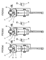
Fig. 2(a) is a schematic illustration showing a state in which a combustion chamber is opened in a contact mode.Fig. 2 (b) is a schematic illustration showing a state in which the combustion chamber is closed in the contact mode.Fig. 2(c) is a schematic illustration showing a state in which a driver is driven. -
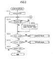
Fig. 3 is a flow chart for explaining an initial operation form of the above gas combustion type driving tool. -
Fig. 4 is a flow chart for explaining an operation form of the contact mode of the above gas combustion type driving tool. -
Fig. 5 is a flow chart for explaining an operation form of a trigger mode of the above gas combustion type driving tool. -
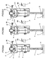
Fig. 6(a) is a schematic illustration for explaining a state in which a piston is moved upward after the completion of driving a nail in the contact mode.Fig. 6 (b) is a schematic illustration showing a state in which combustion gas is exhausted when a combustion chamber is opened in the contact mode.Fig. 6(c) is a schematic illustration showing a state in which the combustion chamber is closed and fuel gas is injected in the contact mode. -
Fig. 7(a) is a schematic illustration showing a state in which the combustion chamber is opened in the trigger mode. -
Fig. 7 (b) is a schematic illustration showing a state in which the combustion chamber is tightly closed in the trigger mode. -
Fig. 7 (c) is .a schematic illustration showing a state in which the driver is driven. -
Fig. 8(a) is a schematic illustration showing a state in which the piston is moved upward after the completion of driving a nail in the trigger mode.Fig. 8(b) is a schematic illustration showing a state in which combustion gas is exhausted when the combustion chamber is opened in the trigger mode.Fig. 8 (c) is a schematic illustration showing a state in which the combustion chamber is closed and the fuel gas is injected in the trigger mode. -
- 4
- Driving piston and cylinder mechanism
- 5
- Combustion chamber
- 6
- Nose portion
- 9
- Driving cylinder
- 10
- Driving piston
- 11
- driver
- 13
- Cylinder head
- 14
- Movable sleeve
- 15
- Contact arm
- 16
- Trigger lever
- 18
- Injection nozzle
- 20
- Rotary fan
- 21
- Ignition plug
- 25
- Control portion
- 26
- Timer function
- SW1
- Contact switch
- SW2
- Trigger switch
-
Fig. 1 is a conceptual view showing a gas combustion type driving tool of an exemplary embodiment of the present invention. Abody 1 of a gas combustion type driving tool includes: agrip 2; amagazine 3 connected to thegrip 2; a driving piston andcylinder mechanism 4; acombustion chamber 5; and anose portion 6. - Nails or pins, which are fasteners, are charged into the
magazine 3. By a mechanism not shown in the drawing, the nails or pins are sent to thenose portion 6 in order. - As shown in
Fig. 2(a) , the driving piston andcylinder mechanism 4 includes adriving piston 10 which is slidably accommodated in thedriving cylinder 9. The driving piston andcylinder mechanism 4 further includes adriver 11 which is integrally provided in a lower portion of thedriving piston 10. - The
combustion chamber 5 includes: an upper end face of thedriving piston 10; adriving cylinder 9; acylinder head 13 arranged in an upper portion of thebody 1; and a cylindricalmovable sleeve 14. As shown inFig. 2(b) , when themovable sleeve 14 is moved upward by an electric motor mechanism not shown in the drawing, the airtightlyclosed combustion chamber 5 is formed. On the other hand, when the movable sleeve 1.4 is moved downward, as shown inFig. 2(a) , thecylinder head 13 and themovable sleeve 14 are separated from each other and an upper portion of thecombustion chamber 5 is communicated and opened to the atmosphere. - The
contact arm 15 is provided so that it can be freely slid in the vertical direction along thenose portion 6. Thelower end 15a of thecontact arm 15 protrudes from thenose portion 6. As shown inFig. 2(c) , when theforward end portion 15a of thecontact arm 15 is pressed against a workpiece P, into which a nail is driven, together with thenose portion 6, thecontact arm 15 is moved upward relatively with respect to thenose portion 6. Therefore, an upper end portion of thelever 15b extending upward is engaged with the contact switch SW1, so that the contact switch SW1 can be electrically turned on. - This gas combustion type driving tool includes: a contact switch SW1 turned on and off when the
contact arm 15 described above is moved in the vertical direction; a trigger switch SW2 electrically turned on when thetrigger lever 16 is pulled; aninjection nozzle 18 for injecting fuel gas, which is charged in thegas bomb 17, into thecombustion chamber 5; arotary fan 20 for stirring air in thecombustion chamber 5 and forcibly exhausting the combustion gas generated after the combustion; anignition plug 21 for igniting the mixed gas generated when air in thecombustion chamber 5 and fuel gas are stirred by therotary fan 20; an electric motor mechanism not shown for moving themovable sleeve 14 in the vertical direction; and acontrol portion 25 for controlling other components. - The
control portion 25 includes MPU having atimer function 26 and a built-inmemory 27. According to the control program stored in the built-inmemory 27, this MPU judges states of the contact switch SW1 and the trigger switch SW2 and also judges the operation time of the timer 26 (the combustionchamber holding timer 26a, the fan-off timer 26b and the combustionchamber opening timer 26c) and controls themovable sleeve 14, theinjection nozzle 18, therotary fan 20 and theignition plug 21. - Next, referring to the flow charts shown in
Figs. 3 to 5 , an operation form of the gas combustion type driving tool composed as described above will be explained below. - When a worker turns on the electric power source so as to use the gas combustion type driving tool, the initialization is executed so that the electric circuit can be initialized (step ST1). In step ST2, the
control portion 25 judges whether or not the fan-off timer 26b is counted up. Since the fan-off timer 26b is reset after the initialization, the program proceeds to step ST4 and the states of the trigger switch SW2 and the contact switch SW1 are checked. When it is in the middle of working, therotary fan 20 is rotating. Therefore, if it is counted up, therotary fan 20 is stopped in step ST3 and the fan-off timer 26b is reset and the program proceeds to step ST4. - In step ST4, it is judged by the trigger switch SW2 whether or not the worker pulls the trigger lever. When the trigger switch SW2 is turned on, the program proceeds to a routine of the contact mode. When the trigger switch SW2 is not turned on, the program proceeds to step ST5. Then, it is judged by the contact switch SW1 whether or not the worker has prepared for driving a nail by pressing the
contact arm 15 against the workpiece P. In the case where the contact switch SW1 is turned on, the program proceeds to a routine of the trigger mode. Either the contact mode or the trigger mode can be carried out by whether the worker first pulls the trigger lever at the time of starting to drive a nail or the worker first presses the contact arm against the workpiece P. - In the case where either switch is not turned on, the steps ST2 to ST6 are looped until the electric power source is turned off and the program waits until the switch is turned on.
- In the contact mode, in step ST101, the fan-
off timer 26b is reset and therotary fan 20 is rotated. Then, the program proceeds to step ST102 so as to move themovable sleeve 14 upward and close thecombustion chamber 5. Concerning this matter, refer toFig. 2(b) . - After that, the
injection nozzle 18 is opened for a predetermined period of time so that the fuel gas can be injected into thecombustion chamber 5 which has been closed. Since therotary fan 20 is rotating at this time, the fuel gas is stirred with air in thecombustion chamber 5 and mixed gas is generated. In this way, the preparation for driving nails is completed (step ST103). - After the preparation for driving nails has been made, the
control portion 25 judges whether the worker executes driving the nails or the worker interrupts driving a nail (step ST104). In the case where the trigger switch SW2 is turned off, it is judged that the nail driving work is interrupted. As shown inFig. 2(a) , themovable sleeve 14 is moved downward and thecombustion chamber 5 is opened (step ST105) so that the mixed gas can be forcibly discharged into the atmosphere. Then the fan-off timer 26b is started and the program is returned to step ST1. - This fan-
off timer 26b is set so that the combustion gas can be completely exhausted. When a period of time (for example, 5 to 10 seconds), which is thought to be sufficiently long for forcibly exhausting the combustion gas by therotary fan 20, is counted, therotary fan 20 is stopped. - When the trigger switch SW2 is turned on in step ST104, it is judged that a nail driving motion is to be executed. Then, the program proceeds to step ST107 and it is waited that the contact switch SW1 is turned on, that is, it is waited that the worker presses the
contact arm 15 against the workpiece P. - When the
contact arm 15 is pressed against the workpiece P and the contact switch SW1 is turned on, the oscillating circuit is turned on (step ST108) and theignition plug 21 is sparked so as to ignite the mixed gas. The mixed gas is explosively burned and as shown inFig. 2 (c) , thedriving piston 10 is moved downward by the pressure of combustion gas. Therefore, the nail is driven from thenose portion 6 into the workpiece P. - After the
ignition plug 21 has been sparked, the program proceeds to step ST109. The combustionchamber holding timer 26a is started and it is waited that thecombustion chamber 5 is cooled and the pressure in thecombustion chamber 5 becomes negative and thedriving piston 10 is returned to the initial position. When the pressure in thecombustion chamber 5 becomes negative, as shown inFig. 6(a) , thedriving piston 10 is moved upward. When the combustionchamber holding timer 26a counts a period of time (not more than one second, preferably about 0.1 second) (the first period) in which thedriving piston 10 is completely returned to the initial position, the program proceeds to step ST111 and themovable sleeve 14 is moved downward so as to open thecombustion chamber 5 and the combustion gas is forcibly exhausted by therotary fan 20. Concerning this matter, refer toFig. 6(b) . - At this point of time, a state of the trigger switch SW2 is judged (step ST112). In the case where the trigger switch SW2 is in a state of being turned on, it is judged that the nail driving motion is continuously executed. Then, the program proceeds to step ST114 and the combustion
chamber opening timer 26c is started and it is waited that a predetermined period of time (the second period) is counted up (step ST115). When the second period is counted up, it is judged that the combustion gas is completely discharged from thecombustion chamber 5 and replaced with fresh air. Then, the program is returned to step ST102 and thecombustion chamber 5 is closed and the fuel gas is injected. Then, it is waited that the contact switch SW1 is turned on. Concerning this matter, refer toFig. 6(c) . - When the trigger switch SW2 is turned off in step ST112, it is judged that the nail driving is singly executed and the fan-
off timer 26b is started and the program is returned to step ST1. Then, the program waits for the next operation in the state ofFig. 2(a) . - In the trigger mode, the fan-
off timer 26b is reset in step ST201 and therotary fan 20 is rotated. Then, the program proceeds to step ST202 and themovable sleeve 14 is moved upward so as to close thecombustion chamber 5. - After that, the program proceeds to step ST203 and the
injection nozzle 18 is opened for a predetermined period of time so that the fuel gas can be injected into thecombustion chamber 5 which has been closed. Since therotary fan 20 is rotated at this point of time, the fuel gas is stirred with air in thecombustion chamber 5 and the mixed gas is generated. In this way, the preparation for driving a nail is completed. Concerning this matter, refer toFig. 7(b) . - When the preparation for driving nails is completed, the
control portion 25 judges whether the worker starts driving the nails or the worker interrupts driving the nails (step ST204). When the contact switch SW1 is turned off, it is judged that the working is to be interrupted. Therefore, themovable sleeve 14 is moved downward and thecombustion chamber 5 is opened (step ST205) so that the mixed gas can be forcibly discharged into the atmosphere. In this state, the fan-off timer 26b is started and the program is returned to step ST2 and the device waits for the next operation in the state shown inFig. 7(a) . - A sufficiently long period of time for exhausting the combustion gas is set on this fan-
off timer 26b. When a period of time (for example, 5 to 10 seconds) (the third period), which is considered to be sufficiently long for forcibly discharging the combustion gas by therotary fan 20 so that the combustion gas can be completely exhausted, is counted, therotary fan 20 is stopped. - When the contact switch SW1 is turned on in ST204, it is judged that the nail driving is to be executed and the program proceeds to step ST207 and it is waited that the trigger switch SW2 is turned on, that is, it is waited that the worker pulls the trigger lever so that a nail can be driven into the workpiece P.
- When the
trigger lever 16 is pulled and the trigger switch SW2 is turned on, the oscillation circuit is turned on (step ST208) and theignition plug 21 is sparked and the mixed gas is ignited. The mixed gas is explosively burned. As shown inFig. 7(c) , thedriving piston 10 is moved downward by the pressure of combustion gas. Therefore, the nail is driven from thenose portion 6 into the workpiece P. - After the
ignition plug 21 has been sparked, the program proceeds to step ST209. The combustionchamber holding timer 26a is started and it is waited that thecombustion chamber 5 is cooled and the pressure in thecombustion chamber 5 becomes negative and thedriving piston 10 is returned to the initial position. When the pressure in thecombustion chamber 5 becomes negative, as shown inFig. 8(a) , thedriving piston 10 is moved upward. When the combustionchamber holding timer 26a counts a period of time (not more than one second, preferably about 0.1 second) (the first period) in which thedriving piston 10 is completely returned to the initial position, the program proceeds to step ST211 and themovable sleeve 14 is moved downward so as to open thecombustion chamber 5 and the combustion gas is forcibly exhausted by therotary fan 20. Concerning this matter, refer toFig. 8(b) . - At this point of time, a state of the contact switch SW1 is judged (step ST212). In the case where the contact switch SW1 is in a state of being turned on, it is judged that the nail driving motion is continuously executed in which while the
contact arm 15 is being pressed against the workpiece P, the nails are continuously driven by shifting the gas combustion type driving tool, that is, it is judged that a so-called shifting driving is executed. Then, the program proceeds to step ST214 and the combustionchamber opening timer 26c is started and it is waited that the timer is counted up (step ST215). After the timer has been counted up, the program returns to step ST202 and thecombustion chamber 5 is closed and the fuel gas is injected into thecombustion chamber 5. Then, it is waited that the trigger switch SW2 is turned on. Concerning this matter, refer toFig. 8(c) . - When the contact switch SW1 is turned off in step ST212, it is judged that the nail driving is singly executed. Therefore, the fan-
off timer 26b is started and the program is returned to step ST2. Then, the program waits for the next operation in the state shown inFig. 7(a) . - As described above, even when the
trigger lever 16 is pulled first or even when thecontact arm 15 is pressed first against the workpiece, it is possible to make preparations for driving the nail. In the case of the contact mode, when thecontact arm 15 is pressed against the workpiece P, theignition plug 21 is sparked so that the nail can be driven.
In the case of the trigger mode, when thetrigger lever 16 is pulled, theignition plug 21 is sparked so that the nail can be driven. Further, when thetrigger lever 16 is kept being pulled after the completion of driving the nail, after thedriving piston 10 has been moved upward by the negative pressure in thecombustion chamber 5, thecombustion chamber 5 is opened, the combustion gas is exhausted, thecombustion chamber 5 is closed and the fuel gas is injected, that is, preparations for driving the nail can be automatically made. Therefore, the nails can be continuously driven. When thecontact arm 15 is kept being pressed against the workpiece P after the completion of driving the nail, after thedriving piston 10 has been moved upward by the negative pressure in thecombustion chamber 5, thecombustion chamber 5 is opened, the combustion gas is exhausted, thecombustion chamber 5 is closed and the fuel gas is injected, that is, preparations for driving the nail can be automatically made. Therefore, the nails can be continuously driven by the shifting driving in which the nails are successively driven while the gas combustion type driving tool is being shifted on the workpiece P. As described above, according to the circumstances of working, the mode of driving the nails can be freely selected and the nails can be continuously driven by the selected mode. In this way, it is possible to realize a gas combustion type driving tool, the operation property and the working efficiency of which are excellent. - While description has been made in connection with specific exemplary embodiment of the invention, it will be obvious to those skilled in the art that various changes and modification may be made within the scope of the appended claims.
- The present application is based on the Japanese Patent Application (No.
2006-328290) filed on December 5, 2006 - The present invention can be applied to a gas combustion type driving tool.
Claims (6)
- A gas combustion type driving tool comprising:a combustion chamber (5);a trigger lever (16); anda contact arm (15),wherein the combustion chamber (5) is closed, fuel gas is injected, air in the combustion chamber (5) and the fuel gas are stirred to each other to generate mixed gas, when the trigger lever (16) is pulled,wherein the mixed gas is ignited, when the contact arm (15) is pressed against a workpiece (P) into which a fastener is driven, andwherein, when a first period has passed after the mixed gas is ignited, the combustion chamber (5) is opened and combustion gas, which is generated by igniting the mixed gas is exhausted,characterized in that the gas combustion type driving tool further comprises:a movable sleeve (14) electrically driven and used for opening and closing the combustion chamber (5);a trigger switch (SW2) electrically turned on when the trigger lever (16) is pulled; anda contact switch (SW1) electrically turned on when the contact arm (15) is pressed against the workpiece (P).
- The gas combustion type driving tool according to claim 1, further comprising:a contact mode; anda trigger mode,wherein, in the contact mode,
when the trigger lever (16) is pulled, the combustion chamber (5) is closed, the fuel gas is injected, the air in the combustion chamber (5) and the fuel gas are stirred, and the mixed gas is generated, and
when the contact arm (15) is pressed against the workpiece (P), the mixed gas is ignited,in the trigger mode,
when the contact arm (15) is pressed against the workpiece (P), the combustion chamber is closed, the fuel gas is injected, the air in the combustion chamber and the fuel gas are stirred to each other, and mixed gas is generated, and
when the trigger lever (16) is pulled, the mixed gas is ignited. - The gas combustion type driving tool according to claim 2, further comprising:a combustion chamber opening timer (26c),wherein, when either the trigger switch (SW2) or the contact switch (SW1) is successively turned on after the combustion chamber (5) is opened, the combustion chamber (5) is closed and the fuel gas is injected after the combustion chamber opening timer (26c) counts a second period.
- The gas combustion type driving tool according to claim 2, further comprising:a fan-off timer (26b),wherein, when both the trigger switch (SW2) and the contact switch (SW1) are turned off after the combustion chamber (5) is opened, a fan (20) is stopped after the fan-off timer (26b) counts a third period.
- The gas combustion type driving tool according to claim 2, further comprising:an ignition plug (21) for igniting the mixed gas; an injection nozzle (18) for injecting the fuel gas into the combustion chamber (5);
a control portion (25),wherein the control portion (25) is configured so that when the control portion (25) detects that the trigger switch (SW2) is turned on and the contact mode is selected, the movable sleeve (14) is operated so as to close the combustion chamber (5), the injection nozzle (18) is operated so as to the inject fuel gas into the combustion chamber (5) for making preparations for driving the fastener into the workpiece (P), and when it is detected that the contact switch (SW1) is turned on after a completion of making preparations for driving the fastener, the ignition plug (21) is operated, andthe control portion (25) is configured so that when the control portion (25) detects that the contact switch (SW1) is turned on and the trigger mode is selected, the movable sleeve (14) is operated so as to close the combustion chamber (5), the injection nozzle (18) is operated so as to inject the fuel gas into the combustion chamber (5) for making preparations for driving the fastener into the workpiece (P), and when it is detected that the trigger switch (SW2) is turned on after the completion of making preparations for driving the fastener, the ignition plug (21) is operated. - A method of operating a gas combustion type driving tool, the method comprising:judging whether a contact mode is selected or a trigger mode is selected,characterized in that the method further comprisesin the contact mode,
closing a combustion chamber (5) by electrically driving a movable sleeve (14), injecting a fuel gas into the combustion chamber (5), stirring air in the combustion chamber (5) and the fuel gas to each other to generate a mixed gas, when a trigger lever (16) is pulled and a trigger switch (SW2) is electrically turned on, and
igniting the mixed gas, when a contact arm (15) is pressed against a workpiece (P) into which a fastener is driven and a contact switch (SW1) is electrically turned on,in the trigger mode,
closing the combustion, chamber (5) by electrically driving the movable sleeve (14), injecting the fuel gas into the combustion chamber (5), stirring the air in the combustion chamber (5) and the fuel gas to each other to generate the mixed gas, when the contact arm (15) is pressed against the workpiece (P) and the contact switch (SW1) is electrically turned on, and
igniting the mixed gas when the trigger lever (16) is pulled and the trigger switch (SW2) is electrically turned on,when a first period is passed after the mixed gas is ignited, the combustion chamber (5) is opened by electrically driving the movable sleeve (14) and a combustion gas generated by igniting the mixed gas is exhausted, andafter the combustion chamber (5) is opened, in either case in which the trigger lever (16) is successively pulled or in which the contact arm (15) is successively pressed, after a second period is passed, the combustion chamber (5) is closed by electrically driving the movable sleeve (14) and the fuel gas is injected into the combustion chamber (5).
Applications Claiming Priority (2)
| Application Number | Priority Date | Filing Date | Title |
|---|---|---|---|
| JP2006328290A JP4899840B2 (en) | 2006-12-05 | 2006-12-05 | Gas fired driving tool |
| PCT/JP2007/073420 WO2008069215A1 (en) | 2006-12-05 | 2007-12-04 | Gas combustion type driving tool |
Publications (3)
| Publication Number | Publication Date |
|---|---|
| EP2090403A1 EP2090403A1 (en) | 2009-08-19 |
| EP2090403A4 EP2090403A4 (en) | 2011-05-18 |
| EP2090403B1 true EP2090403B1 (en) | 2012-04-18 |
Family
ID=39492100
Family Applications (1)
| Application Number | Title | Priority Date | Filing Date |
|---|---|---|---|
| EP07850068A Not-in-force EP2090403B1 (en) | 2006-12-05 | 2007-12-04 | Gas combustion type driving tool |
Country Status (9)
| Country | Link |
|---|---|
| US (1) | US8006880B2 (en) |
| EP (1) | EP2090403B1 (en) |
| JP (1) | JP4899840B2 (en) |
| CN (1) | CN101547772B (en) |
| AT (1) | ATE553888T1 (en) |
| AU (1) | AU2007329968A1 (en) |
| CA (1) | CA2670057A1 (en) |
| TW (1) | TWI457211B (en) |
| WO (1) | WO2008069215A1 (en) |
Families Citing this family (9)
| Publication number | Priority date | Publication date | Assignee | Title |
|---|---|---|---|---|
| JP5240648B2 (en) * | 2008-03-12 | 2013-07-17 | 日立工機株式会社 | Combustion type driving tool |
| JP2011088269A (en) * | 2009-09-25 | 2011-05-06 | Makita Corp | Driving tool |
| JP5429010B2 (en) * | 2010-04-02 | 2014-02-26 | マックス株式会社 | Gas combustion type fastening machine |
| JP5556496B2 (en) * | 2010-08-12 | 2014-07-23 | マックス株式会社 | Gas fired driving tool |
| JP2013233609A (en) * | 2012-05-08 | 2013-11-21 | Makita Corp | Driving tool |
| DE102014206076A1 (en) * | 2014-03-31 | 2015-10-01 | Robert Bosch Gmbh | Hand tool, method of operation |
| EP3181295A1 (en) * | 2015-12-18 | 2017-06-21 | HILTI Aktiengesellschaft | Internal combustion operated driving tool |
| EP3524390B1 (en) * | 2018-01-19 | 2022-03-30 | Max Co., Ltd. | Driving tool |
| US11130221B2 (en) | 2019-01-31 | 2021-09-28 | Milwaukee Electric Tool Corporation | Powered fastener driver |
Family Cites Families (20)
| Publication number | Priority date | Publication date | Assignee | Title |
|---|---|---|---|---|
| US3012549A (en) * | 1957-01-30 | 1961-12-12 | Bard | Internal combustion device |
| US3967771A (en) * | 1974-12-16 | 1976-07-06 | Smith James E | Self-contained impact tool |
| US4403722A (en) * | 1981-01-22 | 1983-09-13 | Signode Corporation | Combustion gas powered fastener driving tool |
| US4483473A (en) * | 1983-05-02 | 1984-11-20 | Signode Corporation | Portable gas-powered fastener driving tool |
| US5263439A (en) * | 1992-11-13 | 1993-11-23 | Illinois Tool Works Inc. | Fuel system for combustion-powered, fastener-driving tool |
| US5415136A (en) * | 1993-08-30 | 1995-05-16 | Illinois Tool Works Inc. | Combined ignition and fuel system for combustion-powered tool |
| US5860580A (en) * | 1996-05-03 | 1999-01-19 | Illinois Tool Works Inc. | Piston retention device for combustion-powered tools |
| JP3925793B2 (en) | 2002-08-09 | 2007-06-06 | 日立工機株式会社 | Combustion type driving tool |
| JP4151346B2 (en) * | 2002-08-09 | 2008-09-17 | 日立工機株式会社 | Combustion type driving tool |
| CN1273270C (en) * | 2002-08-09 | 2006-09-06 | 日立工机株式会社 | Nailing gun using gas as power |
| JP4055509B2 (en) * | 2002-08-09 | 2008-03-05 | 日立工機株式会社 | Combustion type driving tool |
| JP4665432B2 (en) * | 2003-06-20 | 2011-04-06 | 日立工機株式会社 | Combustion power tool |
| JP4239731B2 (en) * | 2003-07-04 | 2009-03-18 | マックス株式会社 | Contact mechanism of power driven nailer |
| JP4147403B2 (en) * | 2003-07-31 | 2008-09-10 | マックス株式会社 | Combustion chamber structure of gas-fired impact tool |
| US7341171B2 (en) * | 2004-02-09 | 2008-03-11 | Illinois Tool Works Inc. | Fan control for combustion-powered fastener-driving tool |
| US7163134B2 (en) * | 2004-02-09 | 2007-01-16 | Illinois Tool Works Inc. | Repetitive cycle tool logic and mode indicator for combustion powered fastener-driving tool |
| JP4353110B2 (en) * | 2004-04-19 | 2009-10-28 | 日立工機株式会社 | Combustion nailer |
| JP4923436B2 (en) * | 2005-05-10 | 2012-04-25 | マックス株式会社 | Gas fired driving tool |
| JP4877457B2 (en) * | 2005-05-17 | 2012-02-15 | マックス株式会社 | Nail feed delay mechanism for gas fired driving tools |
| JP2006328290A (en) | 2005-05-30 | 2006-12-07 | Mitsubishi Chemicals Corp | Method of manufacturing granular polymer, method of manufacturing ion-exchange resin and method of manufacturing synthetic adsorbent, as well as anion-exchange resin, cation-exchange resin and synthetic adsorbent |
-
2006
- 2006-12-05 JP JP2006328290A patent/JP4899840B2/en not_active Expired - Fee Related
-
2007
- 2007-12-04 EP EP07850068A patent/EP2090403B1/en not_active Not-in-force
- 2007-12-04 AT AT07850068T patent/ATE553888T1/en active
- 2007-12-04 AU AU2007329968A patent/AU2007329968A1/en not_active Abandoned
- 2007-12-04 CA CA002670057A patent/CA2670057A1/en not_active Abandoned
- 2007-12-04 US US12/517,647 patent/US8006880B2/en not_active Expired - Fee Related
- 2007-12-04 CN CN2007800451146A patent/CN101547772B/en not_active Expired - Fee Related
- 2007-12-04 TW TW096146056A patent/TWI457211B/en not_active IP Right Cessation
- 2007-12-04 WO PCT/JP2007/073420 patent/WO2008069215A1/en active Application Filing
Also Published As
| Publication number | Publication date |
|---|---|
| JP4899840B2 (en) | 2012-03-21 |
| TWI457211B (en) | 2014-10-21 |
| JP2008137142A (en) | 2008-06-19 |
| US20100032467A1 (en) | 2010-02-11 |
| US8006880B2 (en) | 2011-08-30 |
| WO2008069215A1 (en) | 2008-06-12 |
| TW200836891A (en) | 2008-09-16 |
| EP2090403A4 (en) | 2011-05-18 |
| EP2090403A1 (en) | 2009-08-19 |
| CA2670057A1 (en) | 2008-06-12 |
| ATE553888T1 (en) | 2012-05-15 |
| CN101547772A (en) | 2009-09-30 |
| CN101547772B (en) | 2013-05-15 |
| AU2007329968A1 (en) | 2008-06-12 |
Similar Documents
| Publication | Publication Date | Title |
|---|---|---|
| EP2090403B1 (en) | Gas combustion type driving tool | |
| EP1914041B1 (en) | Gas combustion type driving tool | |
| EP1459850B1 (en) | Combustion type power tool having avoiding unit for avoiding overheating to mechanical components in the tool | |
| JP4685212B2 (en) | Combustion power tool | |
| JP4673324B2 (en) | Repetitive cycle tool logic and mode indicators for combustion fastener driven tools | |
| EP1914042B1 (en) | Gas combustion type hammering tool | |
| EP2065138B1 (en) | Gas combustion-type driving tool | |
| EP1657028A2 (en) | Combustion-type power tool | |
| US8070031B2 (en) | Variable ignition delay for combustion nailer | |
| WO2006120947A1 (en) | Fuel gas type hammering tool | |
| EP1693156B1 (en) | Combustion-type power tool having switch protection arrangement | |
| EP1954449B1 (en) | Motor control for combustion nailer based on operating mode | |
| JP4055509B2 (en) | Combustion type driving tool | |
| WO2006025012A1 (en) | Driver blade with auxiliary combustion chamber for combustion powered fastener-driving tool | |
| US20090152316A1 (en) | Selectable firing mode with electromechanical lockout for combustion-powered fastener -driving tool |
Legal Events
| Date | Code | Title | Description |
|---|---|---|---|
| PUAI | Public reference made under article 153(3) epc to a published international application that has entered the european phase |
Free format text: ORIGINAL CODE: 0009012 |
|
| 17P | Request for examination filed |
Effective date: 20090527 |
|
| AK | Designated contracting states |
Kind code of ref document: A1 Designated state(s): AT BE BG CH CY CZ DE DK EE ES FI FR GB GR HU IE IS IT LI LT LU LV MC MT NL PL PT RO SE SI SK TR |
|
| DAX | Request for extension of the european patent (deleted) | ||
| A4 | Supplementary search report drawn up and despatched |
Effective date: 20110420 |
|
| GRAP | Despatch of communication of intention to grant a patent |
Free format text: ORIGINAL CODE: EPIDOSNIGR1 |
|
| GRAS | Grant fee paid |
Free format text: ORIGINAL CODE: EPIDOSNIGR3 |
|
| GRAA | (expected) grant |
Free format text: ORIGINAL CODE: 0009210 |
|
| AK | Designated contracting states |
Kind code of ref document: B1 Designated state(s): AT BE BG CH CY CZ DE DK EE ES FI FR GB GR HU IE IS IT LI LT LU LV MC MT NL PL PT RO SE SI SK TR |
|
| REG | Reference to a national code |
Ref country code: GB Ref legal event code: FG4D |
|
| REG | Reference to a national code |
Ref country code: CH Ref legal event code: NV Representative=s name: BOVARD AG Ref country code: CH Ref legal event code: EP |
|
| REG | Reference to a national code |
Ref country code: IE Ref legal event code: FG4D |
|
| REG | Reference to a national code |
Ref country code: AT Ref legal event code: REF Ref document number: 553888 Country of ref document: AT Kind code of ref document: T Effective date: 20120515 |
|
| REG | Reference to a national code |
Ref country code: DE Ref legal event code: R096 Ref document number: 602007022161 Country of ref document: DE Effective date: 20120614 |
|
| REG | Reference to a national code |
Ref country code: NL Ref legal event code: VDEP Effective date: 20120418 |
|
| REG | Reference to a national code |
Ref country code: AT Ref legal event code: MK05 Ref document number: 553888 Country of ref document: AT Kind code of ref document: T Effective date: 20120418 |
|
| LTIE | Lt: invalidation of european patent or patent extension |
Effective date: 20120418 |
|
| PG25 | Lapsed in a contracting state [announced via postgrant information from national office to epo] |
Ref country code: PL Free format text: LAPSE BECAUSE OF FAILURE TO SUBMIT A TRANSLATION OF THE DESCRIPTION OR TO PAY THE FEE WITHIN THE PRESCRIBED TIME-LIMIT Effective date: 20120418 Ref country code: CY Free format text: LAPSE BECAUSE OF FAILURE TO SUBMIT A TRANSLATION OF THE DESCRIPTION OR TO PAY THE FEE WITHIN THE PRESCRIBED TIME-LIMIT Effective date: 20120418 Ref country code: SE Free format text: LAPSE BECAUSE OF FAILURE TO SUBMIT A TRANSLATION OF THE DESCRIPTION OR TO PAY THE FEE WITHIN THE PRESCRIBED TIME-LIMIT Effective date: 20120418 Ref country code: LT Free format text: LAPSE BECAUSE OF FAILURE TO SUBMIT A TRANSLATION OF THE DESCRIPTION OR TO PAY THE FEE WITHIN THE PRESCRIBED TIME-LIMIT Effective date: 20120418 Ref country code: FI Free format text: LAPSE BECAUSE OF FAILURE TO SUBMIT A TRANSLATION OF THE DESCRIPTION OR TO PAY THE FEE WITHIN THE PRESCRIBED TIME-LIMIT Effective date: 20120418 Ref country code: IS Free format text: LAPSE BECAUSE OF FAILURE TO SUBMIT A TRANSLATION OF THE DESCRIPTION OR TO PAY THE FEE WITHIN THE PRESCRIBED TIME-LIMIT Effective date: 20120818 |
|
| PG25 | Lapsed in a contracting state [announced via postgrant information from national office to epo] |
Ref country code: PT Free format text: LAPSE BECAUSE OF FAILURE TO SUBMIT A TRANSLATION OF THE DESCRIPTION OR TO PAY THE FEE WITHIN THE PRESCRIBED TIME-LIMIT Effective date: 20120820 Ref country code: SI Free format text: LAPSE BECAUSE OF FAILURE TO SUBMIT A TRANSLATION OF THE DESCRIPTION OR TO PAY THE FEE WITHIN THE PRESCRIBED TIME-LIMIT Effective date: 20120418 Ref country code: GR Free format text: LAPSE BECAUSE OF FAILURE TO SUBMIT A TRANSLATION OF THE DESCRIPTION OR TO PAY THE FEE WITHIN THE PRESCRIBED TIME-LIMIT Effective date: 20120719 Ref country code: LV Free format text: LAPSE BECAUSE OF FAILURE TO SUBMIT A TRANSLATION OF THE DESCRIPTION OR TO PAY THE FEE WITHIN THE PRESCRIBED TIME-LIMIT Effective date: 20120418 |
|
| PG25 | Lapsed in a contracting state [announced via postgrant information from national office to epo] |
Ref country code: BE Free format text: LAPSE BECAUSE OF FAILURE TO SUBMIT A TRANSLATION OF THE DESCRIPTION OR TO PAY THE FEE WITHIN THE PRESCRIBED TIME-LIMIT Effective date: 20120418 |
|
| PG25 | Lapsed in a contracting state [announced via postgrant information from national office to epo] |
Ref country code: CZ Free format text: LAPSE BECAUSE OF FAILURE TO SUBMIT A TRANSLATION OF THE DESCRIPTION OR TO PAY THE FEE WITHIN THE PRESCRIBED TIME-LIMIT Effective date: 20120418 Ref country code: NL Free format text: LAPSE BECAUSE OF FAILURE TO SUBMIT A TRANSLATION OF THE DESCRIPTION OR TO PAY THE FEE WITHIN THE PRESCRIBED TIME-LIMIT Effective date: 20120418 Ref country code: RO Free format text: LAPSE BECAUSE OF FAILURE TO SUBMIT A TRANSLATION OF THE DESCRIPTION OR TO PAY THE FEE WITHIN THE PRESCRIBED TIME-LIMIT Effective date: 20120418 Ref country code: EE Free format text: LAPSE BECAUSE OF FAILURE TO SUBMIT A TRANSLATION OF THE DESCRIPTION OR TO PAY THE FEE WITHIN THE PRESCRIBED TIME-LIMIT Effective date: 20120418 Ref country code: AT Free format text: LAPSE BECAUSE OF FAILURE TO SUBMIT A TRANSLATION OF THE DESCRIPTION OR TO PAY THE FEE WITHIN THE PRESCRIBED TIME-LIMIT Effective date: 20120418 Ref country code: SK Free format text: LAPSE BECAUSE OF FAILURE TO SUBMIT A TRANSLATION OF THE DESCRIPTION OR TO PAY THE FEE WITHIN THE PRESCRIBED TIME-LIMIT Effective date: 20120418 Ref country code: DK Free format text: LAPSE BECAUSE OF FAILURE TO SUBMIT A TRANSLATION OF THE DESCRIPTION OR TO PAY THE FEE WITHIN THE PRESCRIBED TIME-LIMIT Effective date: 20120418 |
|
| PLBE | No opposition filed within time limit |
Free format text: ORIGINAL CODE: 0009261 |
|
| STAA | Information on the status of an ep patent application or granted ep patent |
Free format text: STATUS: NO OPPOSITION FILED WITHIN TIME LIMIT |
|
| PG25 | Lapsed in a contracting state [announced via postgrant information from national office to epo] |
Ref country code: IT Free format text: LAPSE BECAUSE OF FAILURE TO SUBMIT A TRANSLATION OF THE DESCRIPTION OR TO PAY THE FEE WITHIN THE PRESCRIBED TIME-LIMIT Effective date: 20120418 |
|
| 26N | No opposition filed |
Effective date: 20130121 |
|
| PG25 | Lapsed in a contracting state [announced via postgrant information from national office to epo] |
Ref country code: ES Free format text: LAPSE BECAUSE OF FAILURE TO SUBMIT A TRANSLATION OF THE DESCRIPTION OR TO PAY THE FEE WITHIN THE PRESCRIBED TIME-LIMIT Effective date: 20120729 |
|
| REG | Reference to a national code |
Ref country code: DE Ref legal event code: R097 Ref document number: 602007022161 Country of ref document: DE Effective date: 20130121 |
|
| PG25 | Lapsed in a contracting state [announced via postgrant information from national office to epo] |
Ref country code: MC Free format text: LAPSE BECAUSE OF NON-PAYMENT OF DUE FEES Effective date: 20121231 Ref country code: BG Free format text: LAPSE BECAUSE OF FAILURE TO SUBMIT A TRANSLATION OF THE DESCRIPTION OR TO PAY THE FEE WITHIN THE PRESCRIBED TIME-LIMIT Effective date: 20120718 |
|
| GBPC | Gb: european patent ceased through non-payment of renewal fee |
Effective date: 20121204 |
|
| REG | Reference to a national code |
Ref country code: IE Ref legal event code: MM4A |
|
| PG25 | Lapsed in a contracting state [announced via postgrant information from national office to epo] |
Ref country code: IE Free format text: LAPSE BECAUSE OF NON-PAYMENT OF DUE FEES Effective date: 20121204 |
|
| PG25 | Lapsed in a contracting state [announced via postgrant information from national office to epo] |
Ref country code: GB Free format text: LAPSE BECAUSE OF NON-PAYMENT OF DUE FEES Effective date: 20121204 Ref country code: MT Free format text: LAPSE BECAUSE OF FAILURE TO SUBMIT A TRANSLATION OF THE DESCRIPTION OR TO PAY THE FEE WITHIN THE PRESCRIBED TIME-LIMIT Effective date: 20120418 |
|
| PG25 | Lapsed in a contracting state [announced via postgrant information from national office to epo] |
Ref country code: TR Free format text: LAPSE BECAUSE OF FAILURE TO SUBMIT A TRANSLATION OF THE DESCRIPTION OR TO PAY THE FEE WITHIN THE PRESCRIBED TIME-LIMIT Effective date: 20120418 |
|
| PG25 | Lapsed in a contracting state [announced via postgrant information from national office to epo] |
Ref country code: LU Free format text: LAPSE BECAUSE OF NON-PAYMENT OF DUE FEES Effective date: 20121204 |
|
| PG25 | Lapsed in a contracting state [announced via postgrant information from national office to epo] |
Ref country code: HU Free format text: LAPSE BECAUSE OF FAILURE TO SUBMIT A TRANSLATION OF THE DESCRIPTION OR TO PAY THE FEE WITHIN THE PRESCRIBED TIME-LIMIT Effective date: 20071204 |
|
| REG | Reference to a national code |
Ref country code: FR Ref legal event code: PLFP Year of fee payment: 9 |
|
| REG | Reference to a national code |
Ref country code: FR Ref legal event code: PLFP Year of fee payment: 10 |
|
| REG | Reference to a national code |
Ref country code: FR Ref legal event code: PLFP Year of fee payment: 11 |
|
| PGFP | Annual fee paid to national office [announced via postgrant information from national office to epo] |
Ref country code: FR Payment date: 20211109 Year of fee payment: 15 |
|
| PGFP | Annual fee paid to national office [announced via postgrant information from national office to epo] |
Ref country code: CH Payment date: 20211116 Year of fee payment: 15 |
|
| PGFP | Annual fee paid to national office [announced via postgrant information from national office to epo] |
Ref country code: DE Payment date: 20220622 Year of fee payment: 16 |
|
| REG | Reference to a national code |
Ref country code: CH Ref legal event code: PL |
|
| PG25 | Lapsed in a contracting state [announced via postgrant information from national office to epo] |
Ref country code: LI Free format text: LAPSE BECAUSE OF NON-PAYMENT OF DUE FEES Effective date: 20221231 Ref country code: CH Free format text: LAPSE BECAUSE OF NON-PAYMENT OF DUE FEES Effective date: 20221231 |
|
| PG25 | Lapsed in a contracting state [announced via postgrant information from national office to epo] |
Ref country code: FR Free format text: LAPSE BECAUSE OF NON-PAYMENT OF DUE FEES Effective date: 20221231 |
|
| REG | Reference to a national code |
Ref country code: DE Ref legal event code: R119 Ref document number: 602007022161 Country of ref document: DE |