EP2090348A1 - Liquid filter and automatic method for cleaning same - Google Patents
Liquid filter and automatic method for cleaning same Download PDFInfo
- Publication number
- EP2090348A1 EP2090348A1 EP07866339A EP07866339A EP2090348A1 EP 2090348 A1 EP2090348 A1 EP 2090348A1 EP 07866339 A EP07866339 A EP 07866339A EP 07866339 A EP07866339 A EP 07866339A EP 2090348 A1 EP2090348 A1 EP 2090348A1
- Authority
- EP
- European Patent Office
- Prior art keywords
- filtering system
- liquid
- pipe
- liquid filtering
- collector pipe
- Prior art date
- Legal status (The legal status is an assumption and is not a legal conclusion. Google has not performed a legal analysis and makes no representation as to the accuracy of the status listed.)
- Granted
Links
Images


Classifications
-
- B—PERFORMING OPERATIONS; TRANSPORTING
- B01—PHYSICAL OR CHEMICAL PROCESSES OR APPARATUS IN GENERAL
- B01D—SEPARATION
- B01D29/00—Filters with filtering elements stationary during filtration, e.g. pressure or suction filters, not covered by groups B01D24/00 - B01D27/00; Filtering elements therefor
- B01D29/11—Filters with filtering elements stationary during filtration, e.g. pressure or suction filters, not covered by groups B01D24/00 - B01D27/00; Filtering elements therefor with bag, cage, hose, tube, sleeve or like filtering elements
- B01D29/114—Filters with filtering elements stationary during filtration, e.g. pressure or suction filters, not covered by groups B01D24/00 - B01D27/00; Filtering elements therefor with bag, cage, hose, tube, sleeve or like filtering elements arranged for inward flow filtration
-
- B—PERFORMING OPERATIONS; TRANSPORTING
- B01—PHYSICAL OR CHEMICAL PROCESSES OR APPARATUS IN GENERAL
- B01D—SEPARATION
- B01D29/00—Filters with filtering elements stationary during filtration, e.g. pressure or suction filters, not covered by groups B01D24/00 - B01D27/00; Filtering elements therefor
- B01D29/11—Filters with filtering elements stationary during filtration, e.g. pressure or suction filters, not covered by groups B01D24/00 - B01D27/00; Filtering elements therefor with bag, cage, hose, tube, sleeve or like filtering elements
- B01D29/13—Supported filter elements
- B01D29/15—Supported filter elements arranged for inward flow filtration
-
- B—PERFORMING OPERATIONS; TRANSPORTING
- B01—PHYSICAL OR CHEMICAL PROCESSES OR APPARATUS IN GENERAL
- B01D—SEPARATION
- B01D29/00—Filters with filtering elements stationary during filtration, e.g. pressure or suction filters, not covered by groups B01D24/00 - B01D27/00; Filtering elements therefor
- B01D29/44—Edge filtering elements, i.e. using contiguous impervious surfaces
- B01D29/46—Edge filtering elements, i.e. using contiguous impervious surfaces of flat, stacked bodies
-
- B—PERFORMING OPERATIONS; TRANSPORTING
- B01—PHYSICAL OR CHEMICAL PROCESSES OR APPARATUS IN GENERAL
- B01D—SEPARATION
- B01D29/00—Filters with filtering elements stationary during filtration, e.g. pressure or suction filters, not covered by groups B01D24/00 - B01D27/00; Filtering elements therefor
- B01D29/50—Filters with filtering elements stationary during filtration, e.g. pressure or suction filters, not covered by groups B01D24/00 - B01D27/00; Filtering elements therefor with multiple filtering elements, characterised by their mutual disposition
- B01D29/56—Filters with filtering elements stationary during filtration, e.g. pressure or suction filters, not covered by groups B01D24/00 - B01D27/00; Filtering elements therefor with multiple filtering elements, characterised by their mutual disposition in series connection
-
- B—PERFORMING OPERATIONS; TRANSPORTING
- B01—PHYSICAL OR CHEMICAL PROCESSES OR APPARATUS IN GENERAL
- B01D—SEPARATION
- B01D29/00—Filters with filtering elements stationary during filtration, e.g. pressure or suction filters, not covered by groups B01D24/00 - B01D27/00; Filtering elements therefor
- B01D29/88—Filters with filtering elements stationary during filtration, e.g. pressure or suction filters, not covered by groups B01D24/00 - B01D27/00; Filtering elements therefor having feed or discharge devices
- B01D29/90—Filters with filtering elements stationary during filtration, e.g. pressure or suction filters, not covered by groups B01D24/00 - B01D27/00; Filtering elements therefor having feed or discharge devices for feeding
- B01D29/902—Filters with filtering elements stationary during filtration, e.g. pressure or suction filters, not covered by groups B01D24/00 - B01D27/00; Filtering elements therefor having feed or discharge devices for feeding containing fixed liquid displacement elements or cores
-
- B—PERFORMING OPERATIONS; TRANSPORTING
- B01—PHYSICAL OR CHEMICAL PROCESSES OR APPARATUS IN GENERAL
- B01D—SEPARATION
- B01D29/00—Filters with filtering elements stationary during filtration, e.g. pressure or suction filters, not covered by groups B01D24/00 - B01D27/00; Filtering elements therefor
- B01D29/88—Filters with filtering elements stationary during filtration, e.g. pressure or suction filters, not covered by groups B01D24/00 - B01D27/00; Filtering elements therefor having feed or discharge devices
- B01D29/90—Filters with filtering elements stationary during filtration, e.g. pressure or suction filters, not covered by groups B01D24/00 - B01D27/00; Filtering elements therefor having feed or discharge devices for feeding
- B01D29/908—Filters with filtering elements stationary during filtration, e.g. pressure or suction filters, not covered by groups B01D24/00 - B01D27/00; Filtering elements therefor having feed or discharge devices for feeding provoking a tangential stream
-
- C—CHEMISTRY; METALLURGY
- C02—TREATMENT OF WATER, WASTE WATER, SEWAGE, OR SLUDGE
- C02F—TREATMENT OF WATER, WASTE WATER, SEWAGE, OR SLUDGE
- C02F1/00—Treatment of water, waste water, or sewage
- C02F1/001—Processes for the treatment of water whereby the filtration technique is of importance
- C02F1/004—Processes for the treatment of water whereby the filtration technique is of importance using large scale industrial sized filters
-
- C—CHEMISTRY; METALLURGY
- C02—TREATMENT OF WATER, WASTE WATER, SEWAGE, OR SLUDGE
- C02F—TREATMENT OF WATER, WASTE WATER, SEWAGE, OR SLUDGE
- C02F2201/00—Apparatus for treatment of water, waste water or sewage
- C02F2201/002—Construction details of the apparatus
- C02F2201/003—Coaxial constructions, e.g. a cartridge located coaxially within another
-
- C—CHEMISTRY; METALLURGY
- C02—TREATMENT OF WATER, WASTE WATER, SEWAGE, OR SLUDGE
- C02F—TREATMENT OF WATER, WASTE WATER, SEWAGE, OR SLUDGE
- C02F2201/00—Apparatus for treatment of water, waste water or sewage
- C02F2201/002—Construction details of the apparatus
- C02F2201/006—Cartridges
-
- C—CHEMISTRY; METALLURGY
- C02—TREATMENT OF WATER, WASTE WATER, SEWAGE, OR SLUDGE
- C02F—TREATMENT OF WATER, WASTE WATER, SEWAGE, OR SLUDGE
- C02F2301/00—General aspects of water treatment
- C02F2301/02—Fluid flow conditions
- C02F2301/024—Turbulent
-
- C—CHEMISTRY; METALLURGY
- C02—TREATMENT OF WATER, WASTE WATER, SEWAGE, OR SLUDGE
- C02F—TREATMENT OF WATER, WASTE WATER, SEWAGE, OR SLUDGE
- C02F2301/00—General aspects of water treatment
- C02F2301/02—Fluid flow conditions
- C02F2301/026—Spiral, helicoidal, radial
-
- C—CHEMISTRY; METALLURGY
- C02—TREATMENT OF WATER, WASTE WATER, SEWAGE, OR SLUDGE
- C02F—TREATMENT OF WATER, WASTE WATER, SEWAGE, OR SLUDGE
- C02F2301/00—General aspects of water treatment
- C02F2301/08—Multistage treatments, e.g. repetition of the same process step under different conditions
-
- C—CHEMISTRY; METALLURGY
- C02—TREATMENT OF WATER, WASTE WATER, SEWAGE, OR SLUDGE
- C02F—TREATMENT OF WATER, WASTE WATER, SEWAGE, OR SLUDGE
- C02F2303/00—Specific treatment goals
- C02F2303/16—Regeneration of sorbents, filters
Definitions
- This invention refers to a filtering system for water and other liquids that includes different filtering stages in the same element, with its cleaning being done automatically by a new procedure.
- the filtering system subject of this invention has a diverse scope of application, being well suited in the agriculture sector, the industrial sector, in desalinisation plants, and the urban and environmental sectors.
- Liquids normally contain in suspension diverse undesired solid particles. Therefore, in order to eliminate the particles that the water and other liquids contain, different types of filters are used.
- the European patent ES 2 200 901 T3 deals with a single-sieve mesh filter with mechanical cleaning by a motor
- invention patent 69206 refers to a filter with cleaning paddles
- the utility model U 9900677 shows a simple ring filter
- U 200201423 presents a filter with double housing of ring cartridges.
- This invention places the filtering elements successively in a single metallic casing, which enormously simplifies the installation, with less energy loss.
- the ease of cleaning, even automatic solves the existing problems, contributing new advantages that will be made clear throughout this description.
- This invention is comprised of a liquid filtering system and its automatic cleaning procedure.
- the device is comprised by the following essential parts:
- the filtering system is comprised, therefore, of a vertical outer cylindrical casing in whose interior are housed the filtering elements necessary to carry out the elimination of solid impurities from the liquid in different successive phases.
- a pipe that penetrates tangentially the lower base of the cylindrical outer casing continuing with a piece to adapt the flow that makes the gradual change from the section to a rectangular section that produces circular movements, for which reason the heavy particles descend and approach the periphery, through the forces of gravity and centrifuge acting on them.
- a trap to collect these heavy particles, which are stored in a lower impurities chamber.
- the fluid flow follows a warped solid surface arranged to drive the fluid with an ascending helicoidal movement.
- the flow with helicoidal movement is used to pull the impurities towards the periphery and the highest areas of the device, removing them from the more active filtering parts, which receive in this way an additional cleaning.
- the following filtering stages are produced by the successive insertion in the flow of different filtering elements with concentric cylindrical surface shapes or of a circular crown for the ring packages.
- a removable watertight lid is placed in the upper base of the aforementioned outer cylindrical casing.
- One or several suction ball mechanisms are situated on this lid to facilitate the inlet and outlet of air in filling and emptying the filter.
- This lid has several circular concentric notches for fastening the filtering elements; on the one with the largest diameter is fastened a cylindrical mesh panel and in the smallest of these notches is centred a spring that produces the compression of a package of slotted rings placed concentrically to the interior collector pipe.
- This spring acts on an omega-shaped piece that guides the spring and whose inner part adapts to the upper part of the interior collector pipe concentric to the outer casing, leaving between both parts a chamber of variable volume, connected by means of a pipe with a small diameter directly to the outlet of the abovementioned interior collector pipe.
- the lower part of the filter is comprised by a chamber which drains all of the impurities, supporting, in addition, the filtering elements. Some one-way hatches allow the flow to exit towards this chamber, with the dirt particles that did not pass through the filtering elements, but never flowing in the other direction.
- filtering systems are installed forming an equipment set of several units. All the filters are connected parallel to each other between the general pipes with the gross liquid inlet and the general outlet collector of clean filtered liquid. Another collector will drain the dirt from the lower chambers. Each one of these three pipes will be equipped with a valve to regulate the flow.
- the operations of filling and emptying the filter are repeated by operating the valve of the filtered liquid collector as many times as is deemed necessary, according to the degree of cleaning required, at which time the entry flow of the gross liquid is reestablished and, closing the drainage outlet, the entry pressure in the filter is recovered as well as its filtering operations.
- the device is comprised of a vertical cylindrical exterior casing (1), whose lower base is closed by a watertight circular lid on which there is placed tangentially a pipe (2) that conducts the entering gross liquid to the filter.
- This pipe is prolonged by means of a piece that makes the gradual change from the circular shape of the pipe to another rectangular shape (4) and adapting to the periphery of the indicated base in a course of approximately half the circumference.
- a trap (5) located in the lower part, traps the heavy particles that have been concentrated there through the action of gravity and the centrifugal force, remaining stored in the lower impurities chamber (6).
- the upper part of this trap is formed by a warped surface (7), whose special shape causes the liquid flow that comes from the semicircular piece to have an ascending helicoidal movement that results tangential to an inserted cylindrical mesh panel (8). This helicoidal movement of the liquid pulls the solid particles towards the periphery and less-active upper parts for filtering.
- the filtering system includes three filtering stages, the cyclonic stage for the separation of the dense solids (5), that of the mesh (8) for the medium-sized particles and that of the rings (9) for the small particles, leaving the solid impurities separated in different areas, which signifies less silting and a reduction of the number of washings needed per filter.
- the upper base of the outer cylindrical casing is closed by a removable lid (11) with watertight elements and closed, generally, by a lever clamp, with this lid having one or several suction ball valves (12), as well as several concentric notches.
- the notch with the largest diameter serves to fasten the mesh panel and the smaller one centres a compression spring (13) of the ring package, which acts on an omega-shaped piece made with thermoplastic, whose central part (14) guides the compression spring and slides on the exterior part of the interior collector pipe (10) leaving between both pieces a variable chamber (15) connected to the lower part of the interior collector pipe by another pipe with a small diameter (16).
- the gravity stage is carried out by closing the valves located on the entry of the tangential pipe (2) to the lower base of the cylindrical casing and the two-way valve located at the outlet of the interior collector pipe (10), at the same time the valve located at the outlet (18) of the lower impurities chamber is opened, with these impurities removed by gravity descending through the one-way hatches (19) swept by the water that is discharged from the filter.
- These one-way hatches are maintained closed by simple mechanisms, for example a spring, and as the pressure gradient is positive, they will not tend to open during filtering.
- the stage of cleaning by reverse flow or backwash is then carried out.
- the valve (25) that communicates with the filtered liquid connector is opened.
- the pipe with a small diameter (16) provides water to the variable chamber (15) at the maximum pressure so that the action of the spring gives way and the ring package is released.
- the water shooting out of the slanted holes of the interior collector pipe (10) produces on the rings a spinning movement with multiple movements to release the particles retained in their slots.
- the cleaning operations are enhanced by the action of two floating brushes (17) that scrape the mesh and the rings when the move up and down with the level of the liquid in the filter.
- the filters are placed parallel between the general collector of the entering gross liquid (20) and the general outlet collector of filtered liquid (21). Each filter has an outlet that collects the cleaning water in the drainage collector (22). The flow of all the collectors is regulated by means of the corresponding valves.
- the general outlet of the liquid must remain at an approximately constant pressure, which does not usually occur in the filtering equipment currently marketed, since the outlet pressure is greater when the filters are clean and lower when the filters are silted, becoming minimal when the cleaning begins, since in addition one must divert the backwash flow.
- a pressure regulating mechanism is installed downstream in one or several outlet valves (23), which guarantees a constant operating pressure in the network, even when the backwash process is started. In this way only the filters equipped in their outlet valve with a regulator device will work at a variable flow, with the functioning of the remaining valves being at optimal flow, which facilitates the greater pulling of the dirt to the peripheral and upper areas by the helicoidal movement of the liquid.
- the cleaning order by minimal differential pressure, by flow or by time, it proceeds sequentially to each filter, leaving for the end the filters with regulating valves, if there were any.
- the valves (23 and 25) are closed, except that of the drainage (24), in whose layout the liquid content in the filter is discharged, pulling the dirt through the draining collector.
- the filtered liquid valve (23) is opened, letting a sufficient amount to enter to perform the backwash process, then this inlet is shut off and it is allowed to drain out, repeating the operation as many times as required depending on the degree of cleaning required.
Landscapes
- Chemical & Material Sciences (AREA)
- Chemical Kinetics & Catalysis (AREA)
- Life Sciences & Earth Sciences (AREA)
- Hydrology & Water Resources (AREA)
- Engineering & Computer Science (AREA)
- Environmental & Geological Engineering (AREA)
- Water Supply & Treatment (AREA)
- Organic Chemistry (AREA)
- Filtration Of Liquid (AREA)
- Cyclones (AREA)
- Centrifugal Separators (AREA)
Abstract
Description
- This invention refers to a filtering system for water and other liquids that includes different filtering stages in the same element, with its cleaning being done automatically by a new procedure.
- The filtering system subject of this invention has a diverse scope of application, being well suited in the agriculture sector, the industrial sector, in desalinisation plants, and the urban and environmental sectors.
- Liquids normally contain in suspension diverse undesired solid particles. Therefore, in order to eliminate the particles that the water and other liquids contain, different types of filters are used.
- In agriculture, the physical cleaning of the water is necessary in localised irrigation procedures, for which reason the use of different filters is required, which are known as sand, mesh and ring filters, according to their filtering element. Cyclones are also used, referred to in this manner because their filtering is based on centrifugal force.
- Industry also uses filtering systems, although in processes or for the dumping of polluted water to public channels; after passing through the filters, the water is more environmentally tolerable.
- The following patents are known: the
European patent ES 2 200 901 T3 U 9900677 U 200201423 - The different types of existing filtering systems intend to obtain water without solid particles with a diameter over a certain value, and with easy cleaning when they become silted. These objectives are not easily obtained. Normally different filters are placed in a series, inside a shed built for the purpose, requiring a large space and connection pieces. The energy losses are high, as a consequence of designs not taking care of this aspect and of their installation.
- This invention places the filtering elements successively in a single metallic casing, which enormously simplifies the installation, with less energy loss. In addition, the ease of cleaning, even automatic, solves the existing problems, contributing new advantages that will be made clear throughout this description.
- This invention is comprised of a liquid filtering system and its automatic cleaning procedure. The device is comprised by the following essential parts:
- A vertical cylindrical outer casing in whose interior are housed the filtering elements necessary to carry out the elimination of solid impurities in different successive phases.
- A pipe that penetrates tangentially through the lower base of the abovementioned outer cylindrical casing through which the liquid to be filtered enters.
- An interior collector pipe concentric to the outer casing with a lower outlet for the filtered liquid.
- A removable, watertight lid placed in the upper base of the outer cylindrical casing.
- The filtering system is comprised, therefore, of a vertical outer cylindrical casing in whose interior are housed the filtering elements necessary to carry out the elimination of solid impurities from the liquid in different successive phases. For the entry of the liquid to be filtered, there is a pipe that penetrates tangentially the lower base of the cylindrical outer casing continuing with a piece to adapt the flow that makes the gradual change from the section to a rectangular section that produces circular movements, for which reason the heavy particles descend and approach the periphery, through the forces of gravity and centrifuge acting on them. In this lower area is placed a trap to collect these heavy particles, which are stored in a lower impurities chamber. Following this first filtering stage, the fluid flow follows a warped solid surface arranged to drive the fluid with an ascending helicoidal movement.
- The flow with helicoidal movement is used to pull the impurities towards the periphery and the highest areas of the device, removing them from the more active filtering parts, which receive in this way an additional cleaning.
- The following filtering stages are produced by the successive insertion in the flow of different filtering elements with concentric cylindrical surface shapes or of a circular crown for the ring packages.
- This arrangement is advisable, in the first place, because all the filtering elements are within the same casing, with a considerable reduction of space and of connection pieces. In the second place, the passing of the fluid is done hydrodynamically, with the filtering elements being successively inserted in the flow of the liquid, without abrupt changes in its movement, and producing less load loss.
- A removable watertight lid is placed in the upper base of the aforementioned outer cylindrical casing. One or several suction ball mechanisms are situated on this lid to facilitate the inlet and outlet of air in filling and emptying the filter. This lid has several circular concentric notches for fastening the filtering elements; on the one with the largest diameter is fastened a cylindrical mesh panel and in the smallest of these notches is centred a spring that produces the compression of a package of slotted rings placed concentrically to the interior collector pipe. This spring acts on an omega-shaped piece that guides the spring and whose inner part adapts to the upper part of the interior collector pipe concentric to the outer casing, leaving between both parts a chamber of variable volume, connected by means of a pipe with a small diameter directly to the outlet of the abovementioned interior collector pipe.
- The lower part of the filter is comprised by a chamber which drains all of the impurities, supporting, in addition, the filtering elements. Some one-way hatches allow the flow to exit towards this chamber, with the dirt particles that did not pass through the filtering elements, but never flowing in the other direction.
- Normally, filtering systems are installed forming an equipment set of several units. All the filters are connected parallel to each other between the general pipes with the gross liquid inlet and the general outlet collector of clean filtered liquid. Another collector will drain the dirt from the lower chambers. Each one of these three pipes will be equipped with a valve to regulate the flow.
- The functioning of the proposed device is clearly understood after the previous description and is comprised of two well-differentiated processes: the filtering and the cleaning.
- During the filtering process the gross liquid that enters the filter equipment passes through each of them in different stages, leaving the retained solid particles, and with the clean liquid going into the general filtered liquid collector.
- But the dirt accumulated during the filtering silts the filtering elements and must be removed at some time. This cleaning process is begun with the closing of the valve located at the entrance of the tangential pipe at the lower base of the cylindrical casing and the two-way valve located at the outlet of the interior collector pipe, while opening the valve located at the outlet of the lower impurities chamber, and therefore the liquid is discharged through this chamber, pulling the dirt, with two floating brushes housed among the filtering elements collaborating with this, which move by the raising and lowering of the liquid in the filter and scraping the filter surfaces and sweeping away the dirt. Returning the valves to their filtering position again puts the filter in operating order with minimal inactive time.
- A more exhaustive cleaning would be carried out from the previous gravity stage, by means of cleaning by reverse flow. In this process, you open the valve that connects to the filtered liquid collector, which now will come from the rest of the filters, which penetrates through the interior collector pipe, starting the cleaning of the set with reverse flow or, as it is also called, backwash. In this situation the maximum pressure, which is found in the connection to the filtered liquid collector, is transmitted through a pipe with a small diameter to the variable chamber comprised between the omega-shaped piece and the upper part of the interior collector pipe, with the spring action giving way and decompressing the package of rings. At the same time water shoots out of the holes in the perforated interior collector pipe, drilled with the appropriate angle and placement so that by hitting the inside of the ring package it produces the spinning and separation of them, enhancing the cleaning of the retained particles in its slots. The reverse flow sweeps the impurities, passing through the one-way hatches to the lower impurities chamber and together with the dense solids trapped during the gravity stage, all pass to the outside.
- The operations of filling and emptying the filter are repeated by operating the valve of the filtered liquid collector as many times as is deemed necessary, according to the degree of cleaning required, at which time the entry flow of the gross liquid is reestablished and, closing the drainage outlet, the entry pressure in the filter is recovered as well as its filtering operations.
- Both processes can always be done manually, but in the equipment comprised by various filter units the automated form is recommended for the proper functioning of the supply network, always ensuring the correct outlet pressure by means of the regulating valve located in the last filter. When this pressure is minimal, the sequence of washing the filters begins, normally controlled by programming.
-
-
Figure 1 represents the elevation of the filter, sectioned by a quarter. -
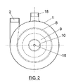
Figure 2 shows the plan of the filter. -
Figures 3 and 4 outline the directions of the flow in the filtering process and in cleaning. - Below is a complete description of a preferred execution of the aforementioned device, which is presented an example but with a non-limiting nature, susceptible to all the modifications of details that do not fundamentally alter its essential characteristics.
- The device is comprised of a vertical cylindrical exterior casing (1), whose lower base is closed by a watertight circular lid on which there is placed tangentially a pipe (2) that conducts the entering gross liquid to the filter. This pipe is prolonged by means of a piece that makes the gradual change from the circular shape of the pipe to another rectangular shape (4) and adapting to the periphery of the indicated base in a course of approximately half the circumference. Next a trap (5), located in the lower part, traps the heavy particles that have been concentrated there through the action of gravity and the centrifugal force, remaining stored in the lower impurities chamber (6). The upper part of this trap is formed by a warped surface (7), whose special shape causes the liquid flow that comes from the semicircular piece to have an ascending helicoidal movement that results tangential to an inserted cylindrical mesh panel (8). This helicoidal movement of the liquid pulls the solid particles towards the periphery and less-active upper parts for filtering.
- With a smaller radius there is a package of slotted rings (9) concentric to an interior collector pipe (10) concentric to the exterior casing, that is perforated and welded to the lower lid, passing through it to serve as the final outlet element of the filtered liquid. A threaded terminal or other joining element allows coupling between the filter and the aforementioned interior collector pipe.
- The filtering system includes three filtering stages, the cyclonic stage for the separation of the dense solids (5), that of the mesh (8) for the medium-sized particles and that of the rings (9) for the small particles, leaving the solid impurities separated in different areas, which signifies less silting and a reduction of the number of washings needed per filter.
- The upper base of the outer cylindrical casing is closed by a removable lid (11) with watertight elements and closed, generally, by a lever clamp, with this lid having one or several suction ball valves (12), as well as several concentric notches. The notch with the largest diameter serves to fasten the mesh panel and the smaller one centres a compression spring (13) of the ring package, which acts on an omega-shaped piece made with thermoplastic, whose central part (14) guides the compression spring and slides on the exterior part of the interior collector pipe (10) leaving between both pieces a variable chamber (15) connected to the lower part of the interior collector pipe by another pipe with a small diameter (16).
- When a single filtering system is used, cleaning is done manually, removing the upper lid through which all the elements to be clean come out, but when there are several units that make up the filtering equipment, the filters can be cleaned sequentially in two complementary ways. The gravity stage is carried out by closing the valves located on the entry of the tangential pipe (2) to the lower base of the cylindrical casing and the two-way valve located at the outlet of the interior collector pipe (10), at the same time the valve located at the outlet (18) of the lower impurities chamber is opened, with these impurities removed by gravity descending through the one-way hatches (19) swept by the water that is discharged from the filter. These one-way hatches are maintained closed by simple mechanisms, for example a spring, and as the pressure gradient is positive, they will not tend to open during filtering.
- The stage of cleaning by reverse flow or backwash is then carried out. In this process, the valve (25) that communicates with the filtered liquid connector is opened. Then, the pipe with a small diameter (16) provides water to the variable chamber (15) at the maximum pressure so that the action of the spring gives way and the ring package is released. In this reverse flow operation, the water shooting out of the slanted holes of the interior collector pipe (10) produces on the rings a spinning movement with multiple movements to release the particles retained in their slots. The cleaning operations are enhanced by the action of two floating brushes (17) that scrape the mesh and the rings when the move up and down with the level of the liquid in the filter.
- The filters are placed parallel between the general collector of the entering gross liquid (20) and the general outlet collector of filtered liquid (21). Each filter has an outlet that collects the cleaning water in the drainage collector (22). The flow of all the collectors is regulated by means of the corresponding valves.
- In the filtering process the general outlet of the liquid must remain at an approximately constant pressure, which does not usually occur in the filtering equipment currently marketed, since the outlet pressure is greater when the filters are clean and lower when the filters are silted, becoming minimal when the cleaning begins, since in addition one must divert the backwash flow. To avoid this, a pressure regulating mechanism is installed downstream in one or several outlet valves (23), which guarantees a constant operating pressure in the network, even when the backwash process is started. In this way only the filters equipped in their outlet valve with a regulator device will work at a variable flow, with the functioning of the remaining valves being at optimal flow, which facilitates the greater pulling of the dirt to the peripheral and upper areas by the helicoidal movement of the liquid.
- According to the cleaning order by minimal differential pressure, by flow or by time, it proceeds sequentially to each filter, leaving for the end the filters with regulating valves, if there were any. In the first place, the valves (23 and 25) are closed, except that of the drainage (24), in whose layout the liquid content in the filter is discharged, pulling the dirt through the draining collector. Then the filtered liquid valve (23) is opened, letting a sufficient amount to enter to perform the backwash process, then this inlet is shut off and it is allowed to drain out, repeating the operation as many times as required depending on the degree of cleaning required.
- The change of valves, passing of the gross liquid and the closing of the drainage, leaves the filter in its filtering operation. The entire sequence of operations for complex installations must be entrusted to automatic programming.
Claims (13)
- Liquid filtering system characterized by being comprised of the following essential parts:• A vertical cylindrical outer casing in whose interior are housed the filtering elements necessary to eliminate the solid impurities in different successive phases.• A pipe that penetrates tangentially through the lower base of the abovementioned outer cylindrical casing through which the liquid to be filtered enters.• An interior collector pipe concentric to the outer casing with a lower outlet for the filtered liquid.• A removable hermetic lid placed in the upper base of the outer cylindrical casing.
- Liquid filtering system according to claim 1 characterized by the pipe that penetrates tangentially on the lower based of the cylindrical casing continuing with a flow adaptation piece that makes the gradual change from the pipe section to a rectangular section that produces circular paths, for which reason the heavy particles descend and approach the periphery, by acting on them the forces of gravity and centrifuge.
- Liquid filtering system according to claims 1 and 2 characterized by the interior collector pipe concentric to the outer casing being perforated and welded to the lower lid, passing through it to serve as the final outlet element of the filtered liquid.
- Liquid filtering system according to claims 1 to 3 characterized by the placement in lower area of a trap to collect the heave particles that remain stored in a lower impurities chamber that contains one-way hatches operated by a spring.
- Liquid filtering system according to claims 1 to 4 characterized by the placement in the upper part of the outer cylindrical casing of a removable watertight lid in which are affixed one or several suction ball mechanisms to facilitate the inlet and outlet of air in the filling and emptying of the filter.
- Liquid filtering system according to claims 1 to 5 characterized by the removable watertight lid having concentric circular notches for fastening the filtering elements.
- Liquid filtering system according to claims 1 to 6 characterized by the fastening of a cylindrical mesh panel on the concentric circular notch with the largest diameter.
- Liquid filtering system according to claims 1 to 7 characterized by centring a spring on the notch with the smallest diameter, which produces the compression of a package of slotted rings placed concentric to the interior collector pipe.
- Liquid filtering system according to claims 1 to 8 characterized by an omega-shaped piece that guides the spring and adapts to the upper part of the interior collector pipe concentric to the outer casing, leaving between both parts a chamber of variable volume connected to the lower part of the interior collector pipe by a pipe with a small diameter.
- Liquid filtering system according to claims 1 to 9 characterized by housing floating brushes among the filtering elements that move up and down with the level of the liquid in the filter and scrape the filtering surfaces, thus pulling away the dirt.
- Cleaning procedure of the liquid filtering system described in claims 1 to 10 that is comprised by a gravity stage and a second stage of cleaning by reverse flow.
- Cleaning procedure of the liquid filtering system according to claims 1 to 11 characterized by the gravity stage including the following sub-stages:• The valve located on the entrance of the tangential pipe to the lower base of the cylindrical casing and the two-way valve located at the outlet of the interior collector pipe are closed.• The valve located in the outlet of the lower impurities chamber is opened.• The impurities descend by gravity through the one-way hatches, pulled by the liquid, discharged from the filter.
- Cleaning procedure of the liquid filtering system according to claims 1 to 11 characterized by the cleaning stage by reverse flow comprised of the following sub-stages:• The two-way valve located at the outlet of the interior collector pipe is opened.• The pipe with a small diameter that connects the chamber of variable volume to the lower part of the interior collector pipe provides water to this variable chamber at the maximum pressure so that the action of the spring gives way and releases the ring package.• The water shooting from the holes in the interior collector pipe produces in the rings a spinning movement with multiple movements to release the particles retained in their slots.• The reverse flow pulls the impurities passing through the one-way hatches to the lower impurities chamber and together with the dense solids trapped in the gravity stage, they pass to the exterior.
Applications Claiming Priority (2)
| Application Number | Priority Date | Filing Date | Title |
|---|---|---|---|
| ES200603116A ES2277792B2 (en) | 2006-12-05 | 2006-12-05 | FILTER FOR LIQUIDS AND ITS AUTOMATIC CLEANING PROCEDURE. |
| PCT/ES2007/000709 WO2008071814A1 (en) | 2006-12-05 | 2007-12-04 | Liquid filter and automatic method for cleaning same |
Publications (4)
| Publication Number | Publication Date |
|---|---|
| EP2090348A1 true EP2090348A1 (en) | 2009-08-19 |
| EP2090348A4 EP2090348A4 (en) | 2010-09-29 |
| EP2090348B1 EP2090348B1 (en) | 2015-07-08 |
| EP2090348B9 EP2090348B9 (en) | 2016-06-15 |
Family
ID=38330867
Family Applications (1)
| Application Number | Title | Priority Date | Filing Date |
|---|---|---|---|
| EP07866339.0A Active EP2090348B9 (en) | 2006-12-05 | 2007-12-04 | Liquid filter and automatic method for cleaning same |
Country Status (7)
| Country | Link |
|---|---|
| US (1) | US8354031B2 (en) |
| EP (1) | EP2090348B9 (en) |
| ES (2) | ES2277792B2 (en) |
| IL (1) | IL199117A (en) |
| MA (1) | MA31279B1 (en) |
| PT (1) | PT2090348E (en) |
| WO (1) | WO2008071814A1 (en) |
Cited By (2)
| Publication number | Priority date | Publication date | Assignee | Title |
|---|---|---|---|---|
| CN102698484A (en) * | 2012-05-24 | 2012-10-03 | 靖江康爱特环境工程有限公司 | Full-automatic filter cake layer filter and filtering method thereof |
| EP2943263A4 (en) * | 2013-01-08 | 2016-07-06 | United Technologies Corp | Fuel system with ice and large debris separator filter |
Families Citing this family (6)
| Publication number | Priority date | Publication date | Assignee | Title |
|---|---|---|---|---|
| ES2277792B2 (en) * | 2006-12-05 | 2008-06-16 | Universidad Politecnica De Madrid | FILTER FOR LIQUIDS AND ITS AUTOMATIC CLEANING PROCEDURE. |
| CN104944517B (en) * | 2015-06-03 | 2017-08-08 | 中国水利水电科学研究院 | It is a kind of from blowdown centrifugal filter |
| CN107080994B (en) * | 2017-06-20 | 2018-03-02 | 湖北君集水处理有限公司 | A kind of self-cleaning pot type filter separator |
| CN112169414A (en) * | 2020-10-21 | 2021-01-05 | 恒河材料科技股份有限公司 | Petrochemical product filters edulcoration equipment |
| CN112174252B (en) * | 2020-11-10 | 2025-02-11 | 中科瑞丽分离科技无锡有限公司 | An oil-water separator for treating emulsified oil |
| CN113731003B (en) * | 2021-09-23 | 2023-01-20 | 延安地丰石油工程技术服务有限公司 | Vibrating filtration equipment for oil exploitation |
Family Cites Families (19)
| Publication number | Priority date | Publication date | Assignee | Title |
|---|---|---|---|---|
| FR1345705A (en) * | 1962-10-30 | 1963-12-13 | filter element provided with one or more pre-filter sleeves | |
| US3400820A (en) * | 1965-03-30 | 1968-09-10 | Bird Machine Co | Screening apparatus with rotary pulsing member |
| IL74527A0 (en) | 1985-03-07 | 1985-06-30 | Amiad Sinon Vehashkaya | Fluid filtering device |
| AU642545B2 (en) * | 1991-11-01 | 1993-10-21 | Tsung-Hai Chen | Filter automatic cleansing water cleaner |
| US5490924A (en) * | 1994-07-20 | 1996-02-13 | Control Systems Innovations, Inc. | Filtration system |
| FR2772635B1 (en) * | 1997-12-18 | 2000-06-16 | Snecma | AUTOLAVABLE DEVICE FOR SEPARATION AND FILTRATION OF SOLID PARTICLES IN A FLOW OF LIQUID AND APPLICATION TO A FUEL INJECTION CIRCUIT INCLUDING SUCH A DEVICE |
| ES1040967Y (en) * | 1998-07-22 | 1999-10-16 | Wind S A | PERFECTED SELF-CLEANING FILTER. |
| DE69810821T2 (en) * | 1998-07-24 | 2003-10-09 | Wind, S.L. | SELF-CLEANING FILTER |
| ES1042502Y (en) | 1999-03-16 | 2000-02-01 | Sistema Azud S A | PERFECTED SLOTTED DISC FILTER. |
| US6267879B1 (en) * | 1999-08-11 | 2001-07-31 | Odis Irrigation Equipment Ltd. | Continuous liquid filtering apparatus with multi-layer sintered filtering element |
| NO312945B1 (en) * | 2000-02-24 | 2002-07-22 | Trygve Lunde | Device for separating particles in a liquid |
| WO2001093982A1 (en) | 2000-06-09 | 2001-12-13 | Agricultural Products, Inc. | An agricultural or industrial spin filter and a method of operation for same |
| ES1048818Y (en) * | 2001-03-30 | 2002-07-16 | Filtromatic S L | PERFECTED CARTRIDGE FILTER. |
| DE20106755U1 (en) * | 2001-04-19 | 2001-08-16 | Runge, Eberhard, 22419 Hamburg | Deep fine filter |
| US6869782B2 (en) | 2001-07-10 | 2005-03-22 | Canon Kabushiki Kaisha | Polyhydroxyalkanoate that comprises unit having (methylsulfanyl) phenoxy structure in side chain thereof and process for producing the same |
| US6632352B2 (en) * | 2001-07-11 | 2003-10-14 | Nursery Pro, Inc. | Multi-stage filter |
| EP1308195A1 (en) * | 2001-11-05 | 2003-05-07 | Joseph Kuo | Laminated modular water filter |
| ES1052105Y (en) * | 2002-06-04 | 2003-03-01 | Sist Azud S A | BODY FOR MULTIPLE CARTRIDGE FILTER. |
| ES2277792B2 (en) * | 2006-12-05 | 2008-06-16 | Universidad Politecnica De Madrid | FILTER FOR LIQUIDS AND ITS AUTOMATIC CLEANING PROCEDURE. |
-
2006
- 2006-12-05 ES ES200603116A patent/ES2277792B2/en active Active
-
2007
- 2007-12-04 WO PCT/ES2007/000709 patent/WO2008071814A1/en not_active Ceased
- 2007-12-04 PT PT78663390T patent/PT2090348E/en unknown
- 2007-12-04 EP EP07866339.0A patent/EP2090348B9/en active Active
- 2007-12-04 ES ES07866339.0T patent/ES2549431T3/en active Active
- 2007-12-04 US US12/517,478 patent/US8354031B2/en not_active Expired - Fee Related
-
2009
- 2009-06-03 IL IL199117A patent/IL199117A/en active IP Right Grant
- 2009-06-03 MA MA31949A patent/MA31279B1/en unknown
Cited By (3)
| Publication number | Priority date | Publication date | Assignee | Title |
|---|---|---|---|---|
| CN102698484A (en) * | 2012-05-24 | 2012-10-03 | 靖江康爱特环境工程有限公司 | Full-automatic filter cake layer filter and filtering method thereof |
| CN102698484B (en) * | 2012-05-24 | 2015-11-25 | 靖江康爱特环境工程有限公司 | Full-automatic filter cake layer filter and filter method thereof |
| EP2943263A4 (en) * | 2013-01-08 | 2016-07-06 | United Technologies Corp | Fuel system with ice and large debris separator filter |
Also Published As
| Publication number | Publication date |
|---|---|
| IL199117A (en) | 2015-04-30 |
| EP2090348B9 (en) | 2016-06-15 |
| ES2549431T3 (en) | 2015-10-28 |
| EP2090348B1 (en) | 2015-07-08 |
| MA31279B1 (en) | 2010-04-01 |
| WO2008071814A1 (en) | 2008-06-19 |
| EP2090348A4 (en) | 2010-09-29 |
| PT2090348E (en) | 2015-10-26 |
| ES2277792A1 (en) | 2007-07-16 |
| ES2277792B2 (en) | 2008-06-16 |
| US20100140183A1 (en) | 2010-06-10 |
| US8354031B2 (en) | 2013-01-15 |
Similar Documents
| Publication | Publication Date | Title |
|---|---|---|
| US8354031B2 (en) | Liquid filtering system and its automatic cleaning procedure | |
| CN105916565B (en) | Filter core and filter | |
| US12311290B2 (en) | Enclosed media fluid filtration device | |
| CN110054312A (en) | A kind of vortex dirt-remover | |
| CN120083287A (en) | A rainwater and sewage diversion interception well and diversion interception method | |
| CN211799300U (en) | Backwashing filter box for ornamental water | |
| CN219098935U (en) | Rainwater cyclone filter | |
| RU2503622C1 (en) | Effluents industrial effluents treatment plant | |
| EP1169104A1 (en) | Waste water filtration tank | |
| JP2020093240A (en) | Filtration device | |
| CN216972074U (en) | Rotary drum type efficient oil-water separation device | |
| CN214402090U (en) | Rainwater mud trap | |
| AU2019345932B2 (en) | Immiscible liquids separation apparatus and method | |
| CN214914146U (en) | Automatic back flush water filter of whirl | |
| CN205867773U (en) | Centrifugal self -cleaning filter of multistage high efficiency | |
| CN113951797A (en) | Shoe washing machine | |
| KR102351729B1 (en) | Rainwater filtration and storage device | |
| CN220201500U (en) | Filter equipment for building water supply and drainage engineering | |
| SU1717173A1 (en) | Filter for cleaning liquids | |
| CN215085459U (en) | Multistage filter screen backwashing dirt removing device | |
| CN109826831A (en) | Self priming pump filter device | |
| KR890002200Y1 (en) | Water-cleaning filters | |
| JPS629931Y2 (en) | ||
| CN216320435U (en) | Sewage pipes protector | |
| CN111542381B (en) | Immersion device for swimming pool filtration |
Legal Events
| Date | Code | Title | Description |
|---|---|---|---|
| PUAI | Public reference made under article 153(3) epc to a published international application that has entered the european phase |
Free format text: ORIGINAL CODE: 0009012 |
|
| 17P | Request for examination filed |
Effective date: 20090602 |
|
| AK | Designated contracting states |
Kind code of ref document: A1 Designated state(s): AT BE BG CH CY CZ DE DK EE ES FI FR GB GR HU IE IS IT LI LT LU LV MC MT NL PL PT RO SE SI SK TR |
|
| DAX | Request for extension of the european patent (deleted) | ||
| A4 | Supplementary search report drawn up and despatched |
Effective date: 20100831 |
|
| RIC1 | Information provided on ipc code assigned before grant |
Ipc: B01D 29/15 20060101ALI20100825BHEP Ipc: B01D 36/02 20060101ALI20100825BHEP Ipc: B01D 25/38 20060101AFI20080703BHEP |
|
| 17Q | First examination report despatched |
Effective date: 20110713 |
|
| GRAP | Despatch of communication of intention to grant a patent |
Free format text: ORIGINAL CODE: EPIDOSNIGR1 |
|
| INTG | Intention to grant announced |
Effective date: 20140710 |
|
| GRAS | Grant fee paid |
Free format text: ORIGINAL CODE: EPIDOSNIGR3 |
|
| GRAA | (expected) grant |
Free format text: ORIGINAL CODE: 0009210 |
|
| AK | Designated contracting states |
Kind code of ref document: B1 Designated state(s): AT BE BG CH CY CZ DE DK EE ES FI FR GB GR HU IE IS IT LI LT LU LV MC MT NL PL PT RO SE SI SK TR |
|
| REG | Reference to a national code |
Ref country code: GB Ref legal event code: FG4D |
|
| REG | Reference to a national code |
Ref country code: AT Ref legal event code: REF Ref document number: 734921 Country of ref document: AT Kind code of ref document: T Effective date: 20150715 Ref country code: CH Ref legal event code: EP |
|
| REG | Reference to a national code |
Ref country code: IE Ref legal event code: FG4D |
|
| REG | Reference to a national code |
Ref country code: DE Ref legal event code: R096 Ref document number: 602007042103 Country of ref document: DE |
|
| REG | Reference to a national code |
Ref country code: PT Ref legal event code: SC4A Free format text: AVAILABILITY OF NATIONAL TRANSLATION Effective date: 20151002 |
|
| REG | Reference to a national code |
Ref country code: ES Ref legal event code: FG2A Ref document number: 2549431 Country of ref document: ES Kind code of ref document: T3 Effective date: 20151028 |
|
| REG | Reference to a national code |
Ref country code: AT Ref legal event code: MK05 Ref document number: 734921 Country of ref document: AT Kind code of ref document: T Effective date: 20150708 |
|
| REG | Reference to a national code |
Ref country code: NL Ref legal event code: MP Effective date: 20150708 |
|
| REG | Reference to a national code |
Ref country code: LT Ref legal event code: MG4D |
|
| REG | Reference to a national code |
Ref country code: FR Ref legal event code: PLFP Year of fee payment: 9 |
|
| PG25 | Lapsed in a contracting state [announced via postgrant information from national office to epo] |
Ref country code: GR Free format text: LAPSE BECAUSE OF FAILURE TO SUBMIT A TRANSLATION OF THE DESCRIPTION OR TO PAY THE FEE WITHIN THE PRESCRIBED TIME-LIMIT Effective date: 20151009 Ref country code: FI Free format text: LAPSE BECAUSE OF FAILURE TO SUBMIT A TRANSLATION OF THE DESCRIPTION OR TO PAY THE FEE WITHIN THE PRESCRIBED TIME-LIMIT Effective date: 20150708 Ref country code: LV Free format text: LAPSE BECAUSE OF FAILURE TO SUBMIT A TRANSLATION OF THE DESCRIPTION OR TO PAY THE FEE WITHIN THE PRESCRIBED TIME-LIMIT Effective date: 20150708 Ref country code: LT Free format text: LAPSE BECAUSE OF FAILURE TO SUBMIT A TRANSLATION OF THE DESCRIPTION OR TO PAY THE FEE WITHIN THE PRESCRIBED TIME-LIMIT Effective date: 20150708 |
|
| PG25 | Lapsed in a contracting state [announced via postgrant information from national office to epo] |
Ref country code: IS Free format text: LAPSE BECAUSE OF FAILURE TO SUBMIT A TRANSLATION OF THE DESCRIPTION OR TO PAY THE FEE WITHIN THE PRESCRIBED TIME-LIMIT Effective date: 20151108 Ref country code: AT Free format text: LAPSE BECAUSE OF FAILURE TO SUBMIT A TRANSLATION OF THE DESCRIPTION OR TO PAY THE FEE WITHIN THE PRESCRIBED TIME-LIMIT Effective date: 20150708 Ref country code: PL Free format text: LAPSE BECAUSE OF FAILURE TO SUBMIT A TRANSLATION OF THE DESCRIPTION OR TO PAY THE FEE WITHIN THE PRESCRIBED TIME-LIMIT Effective date: 20150708 Ref country code: SE Free format text: LAPSE BECAUSE OF FAILURE TO SUBMIT A TRANSLATION OF THE DESCRIPTION OR TO PAY THE FEE WITHIN THE PRESCRIBED TIME-LIMIT Effective date: 20150708 |
|
| REG | Reference to a national code |
Ref country code: DE Ref legal event code: R097 Ref document number: 602007042103 Country of ref document: DE |
|
| GRAT | Correction requested after decision to grant or after decision to maintain patent in amended form |
Free format text: ORIGINAL CODE: EPIDOSNCDEC |
|
| PG25 | Lapsed in a contracting state [announced via postgrant information from national office to epo] |
Ref country code: CZ Free format text: LAPSE BECAUSE OF FAILURE TO SUBMIT A TRANSLATION OF THE DESCRIPTION OR TO PAY THE FEE WITHIN THE PRESCRIBED TIME-LIMIT Effective date: 20150708 Ref country code: DK Free format text: LAPSE BECAUSE OF FAILURE TO SUBMIT A TRANSLATION OF THE DESCRIPTION OR TO PAY THE FEE WITHIN THE PRESCRIBED TIME-LIMIT Effective date: 20150708 Ref country code: EE Free format text: LAPSE BECAUSE OF FAILURE TO SUBMIT A TRANSLATION OF THE DESCRIPTION OR TO PAY THE FEE WITHIN THE PRESCRIBED TIME-LIMIT Effective date: 20150708 Ref country code: SK Free format text: LAPSE BECAUSE OF FAILURE TO SUBMIT A TRANSLATION OF THE DESCRIPTION OR TO PAY THE FEE WITHIN THE PRESCRIBED TIME-LIMIT Effective date: 20150708 |
|
| PLBE | No opposition filed within time limit |
Free format text: ORIGINAL CODE: 0009261 |
|
| STAA | Information on the status of an ep patent application or granted ep patent |
Free format text: STATUS: NO OPPOSITION FILED WITHIN TIME LIMIT |
|
| PG25 | Lapsed in a contracting state [announced via postgrant information from national office to epo] |
Ref country code: RO Free format text: LAPSE BECAUSE OF FAILURE TO SUBMIT A TRANSLATION OF THE DESCRIPTION OR TO PAY THE FEE WITHIN THE PRESCRIBED TIME-LIMIT Effective date: 20150708 Ref country code: BE Free format text: LAPSE BECAUSE OF NON-PAYMENT OF DUE FEES Effective date: 20151231 |
|
| 26N | No opposition filed |
Effective date: 20160411 |
|
| REG | Reference to a national code |
Ref country code: DE Ref legal event code: R119 Ref document number: 602007042103 Country of ref document: DE |
|
| PG25 | Lapsed in a contracting state [announced via postgrant information from national office to epo] |
Ref country code: MC Free format text: LAPSE BECAUSE OF FAILURE TO SUBMIT A TRANSLATION OF THE DESCRIPTION OR TO PAY THE FEE WITHIN THE PRESCRIBED TIME-LIMIT Effective date: 20150708 Ref country code: LU Free format text: LAPSE BECAUSE OF FAILURE TO SUBMIT A TRANSLATION OF THE DESCRIPTION OR TO PAY THE FEE WITHIN THE PRESCRIBED TIME-LIMIT Effective date: 20151204 |
|
| REG | Reference to a national code |
Ref country code: CH Ref legal event code: PL |
|
| GBPC | Gb: european patent ceased through non-payment of renewal fee |
Effective date: 20151204 |
|
| PG25 | Lapsed in a contracting state [announced via postgrant information from national office to epo] |
Ref country code: SI Free format text: LAPSE BECAUSE OF FAILURE TO SUBMIT A TRANSLATION OF THE DESCRIPTION OR TO PAY THE FEE WITHIN THE PRESCRIBED TIME-LIMIT Effective date: 20150708 |
|
| REG | Reference to a national code |
Ref country code: IE Ref legal event code: MM4A |
|
| PG25 | Lapsed in a contracting state [announced via postgrant information from national office to epo] |
Ref country code: GB Free format text: LAPSE BECAUSE OF NON-PAYMENT OF DUE FEES Effective date: 20151204 Ref country code: DE Free format text: LAPSE BECAUSE OF NON-PAYMENT OF DUE FEES Effective date: 20160701 Ref country code: CH Free format text: LAPSE BECAUSE OF NON-PAYMENT OF DUE FEES Effective date: 20151231 Ref country code: LI Free format text: LAPSE BECAUSE OF NON-PAYMENT OF DUE FEES Effective date: 20151231 Ref country code: IE Free format text: LAPSE BECAUSE OF NON-PAYMENT OF DUE FEES Effective date: 20151204 |
|
| REG | Reference to a national code |
Ref country code: FR Ref legal event code: PLFP Year of fee payment: 10 |
|
| PG25 | Lapsed in a contracting state [announced via postgrant information from national office to epo] |
Ref country code: BE Free format text: LAPSE BECAUSE OF FAILURE TO SUBMIT A TRANSLATION OF THE DESCRIPTION OR TO PAY THE FEE WITHIN THE PRESCRIBED TIME-LIMIT Effective date: 20150708 |
|
| PG25 | Lapsed in a contracting state [announced via postgrant information from national office to epo] |
Ref country code: BG Free format text: LAPSE BECAUSE OF FAILURE TO SUBMIT A TRANSLATION OF THE DESCRIPTION OR TO PAY THE FEE WITHIN THE PRESCRIBED TIME-LIMIT Effective date: 20150708 Ref country code: HU Free format text: LAPSE BECAUSE OF FAILURE TO SUBMIT A TRANSLATION OF THE DESCRIPTION OR TO PAY THE FEE WITHIN THE PRESCRIBED TIME-LIMIT; INVALID AB INITIO Effective date: 20071204 |
|
| PG25 | Lapsed in a contracting state [announced via postgrant information from national office to epo] |
Ref country code: NL Free format text: LAPSE BECAUSE OF FAILURE TO SUBMIT A TRANSLATION OF THE DESCRIPTION OR TO PAY THE FEE WITHIN THE PRESCRIBED TIME-LIMIT Effective date: 20150708 Ref country code: CY Free format text: LAPSE BECAUSE OF FAILURE TO SUBMIT A TRANSLATION OF THE DESCRIPTION OR TO PAY THE FEE WITHIN THE PRESCRIBED TIME-LIMIT Effective date: 20150708 |
|
| PG25 | Lapsed in a contracting state [announced via postgrant information from national office to epo] |
Ref country code: MT Free format text: LAPSE BECAUSE OF FAILURE TO SUBMIT A TRANSLATION OF THE DESCRIPTION OR TO PAY THE FEE WITHIN THE PRESCRIBED TIME-LIMIT Effective date: 20150708 Ref country code: TR Free format text: LAPSE BECAUSE OF FAILURE TO SUBMIT A TRANSLATION OF THE DESCRIPTION OR TO PAY THE FEE WITHIN THE PRESCRIBED TIME-LIMIT Effective date: 20150708 |
|
| REG | Reference to a national code |
Ref country code: FR Ref legal event code: PLFP Year of fee payment: 11 |
|
| PGFP | Annual fee paid to national office [announced via postgrant information from national office to epo] |
Ref country code: FR Payment date: 20171229 Year of fee payment: 11 |
|
| PGFP | Annual fee paid to national office [announced via postgrant information from national office to epo] |
Ref country code: PT Payment date: 20180103 Year of fee payment: 11 Ref country code: IT Payment date: 20171227 Year of fee payment: 11 |
|
| PG25 | Lapsed in a contracting state [announced via postgrant information from national office to epo] |
Ref country code: PT Free format text: LAPSE BECAUSE OF NON-PAYMENT OF DUE FEES Effective date: 20190604 |
|
| PG25 | Lapsed in a contracting state [announced via postgrant information from national office to epo] |
Ref country code: FR Free format text: LAPSE BECAUSE OF NON-PAYMENT OF DUE FEES Effective date: 20181231 Ref country code: IT Free format text: LAPSE BECAUSE OF NON-PAYMENT OF DUE FEES Effective date: 20181204 |
|
| PGFP | Annual fee paid to national office [announced via postgrant information from national office to epo] |
Ref country code: ES Payment date: 20251231 Year of fee payment: 19 |