EP2089234B1 - Digital printing plastic containers - Google Patents
Digital printing plastic containers Download PDFInfo
- Publication number
- EP2089234B1 EP2089234B1 EP07864674.2A EP07864674A EP2089234B1 EP 2089234 B1 EP2089234 B1 EP 2089234B1 EP 07864674 A EP07864674 A EP 07864674A EP 2089234 B1 EP2089234 B1 EP 2089234B1
- Authority
- EP
- European Patent Office
- Prior art keywords
- container
- ink
- droplets
- digital image
- printed
- Prior art date
- Legal status (The legal status is an assumption and is not a legal conclusion. Google has not performed a legal analysis and makes no representation as to the accuracy of the status listed.)
- Revoked
Links
Images


Classifications
-
- B—PERFORMING OPERATIONS; TRANSPORTING
- B41—PRINTING; LINING MACHINES; TYPEWRITERS; STAMPS
- B41J—TYPEWRITERS; SELECTIVE PRINTING MECHANISMS, i.e. MECHANISMS PRINTING OTHERWISE THAN FROM A FORME; CORRECTION OF TYPOGRAPHICAL ERRORS
- B41J2/00—Typewriters or selective printing mechanisms characterised by the printing or marking process for which they are designed
- B41J2/005—Typewriters or selective printing mechanisms characterised by the printing or marking process for which they are designed characterised by bringing liquid or particles selectively into contact with a printing material
- B41J2/01—Ink jet
- B41J2/17—Ink jet characterised by ink handling
- B41J2/175—Ink supply systems ; Circuit parts therefor
- B41J2/17503—Ink cartridges
- B41J2/17506—Refilling of the cartridge
- B41J2/17509—Whilst mounted in the printer
-
- B—PERFORMING OPERATIONS; TRANSPORTING
- B41—PRINTING; LINING MACHINES; TYPEWRITERS; STAMPS
- B41J—TYPEWRITERS; SELECTIVE PRINTING MECHANISMS, i.e. MECHANISMS PRINTING OTHERWISE THAN FROM A FORME; CORRECTION OF TYPOGRAPHICAL ERRORS
- B41J2/00—Typewriters or selective printing mechanisms characterised by the printing or marking process for which they are designed
- B41J2/005—Typewriters or selective printing mechanisms characterised by the printing or marking process for which they are designed characterised by bringing liquid or particles selectively into contact with a printing material
- B41J2/01—Ink jet
- B41J2/205—Ink jet for printing a discrete number of tones
-
- B—PERFORMING OPERATIONS; TRANSPORTING
- B41—PRINTING; LINING MACHINES; TYPEWRITERS; STAMPS
- B41J—TYPEWRITERS; SELECTIVE PRINTING MECHANISMS, i.e. MECHANISMS PRINTING OTHERWISE THAN FROM A FORME; CORRECTION OF TYPOGRAPHICAL ERRORS
- B41J29/00—Details of, or accessories for, typewriters or selective printing mechanisms not otherwise provided for
- B41J29/377—Cooling or ventilating arrangements
-
- B—PERFORMING OPERATIONS; TRANSPORTING
- B41—PRINTING; LINING MACHINES; TYPEWRITERS; STAMPS
- B41J—TYPEWRITERS; SELECTIVE PRINTING MECHANISMS, i.e. MECHANISMS PRINTING OTHERWISE THAN FROM A FORME; CORRECTION OF TYPOGRAPHICAL ERRORS
- B41J29/00—Details of, or accessories for, typewriters or selective printing mechanisms not otherwise provided for
- B41J29/38—Drives, motors, controls or automatic cut-off devices for the entire printing mechanism
-
- B—PERFORMING OPERATIONS; TRANSPORTING
- B41—PRINTING; LINING MACHINES; TYPEWRITERS; STAMPS
- B41J—TYPEWRITERS; SELECTIVE PRINTING MECHANISMS, i.e. MECHANISMS PRINTING OTHERWISE THAN FROM A FORME; CORRECTION OF TYPOGRAPHICAL ERRORS
- B41J3/00—Typewriters or selective printing or marking mechanisms characterised by the purpose for which they are constructed
- B41J3/407—Typewriters or selective printing or marking mechanisms characterised by the purpose for which they are constructed for marking on special material
- B41J3/4073—Printing on three-dimensional objects not being in sheet or web form, e.g. spherical or cubic objects
-
- B—PERFORMING OPERATIONS; TRANSPORTING
- B65—CONVEYING; PACKING; STORING; HANDLING THIN OR FILAMENTARY MATERIAL
- B65D—CONTAINERS FOR STORAGE OR TRANSPORT OF ARTICLES OR MATERIALS, e.g. BAGS, BARRELS, BOTTLES, BOXES, CANS, CARTONS, CRATES, DRUMS, JARS, TANKS, HOPPERS, FORWARDING CONTAINERS; ACCESSORIES, CLOSURES, OR FITTINGS THEREFOR; PACKAGING ELEMENTS; PACKAGES
- B65D25/00—Details of other kinds or types of rigid or semi-rigid containers
- B65D25/34—Coverings or external coatings
-
- B—PERFORMING OPERATIONS; TRANSPORTING
- B41—PRINTING; LINING MACHINES; TYPEWRITERS; STAMPS
- B41M—PRINTING, DUPLICATING, MARKING, OR COPYING PROCESSES; COLOUR PRINTING
- B41M5/00—Duplicating or marking methods; Sheet materials for use therein
- B41M5/0082—Digital printing on bodies of particular shapes
- B41M5/0088—Digital printing on bodies of particular shapes by ink-jet printing
Definitions
- the present invention relates generally to plastic containers having digital images printed thereon, particularly containers with curved surfaces, and methods for printing images on plastic containers.
- the US 2006/0144261 A1 discloses a plastic container comprising a container having a non-planar external surface with a digital image printed thereon by droplets of ink.
- US2006/250464 A1 discloses a method and apparatus for printing selected information on bottles, by: conveying the bottles sequentially through a predetermined path including at least one printing station; actuating an ink-jet print head at the printing station to discharge liquid ink droplets onto the bottle in the printing station; and controlling the print head at the printing station to discharge the liquid ink droplets onto the bottle in accordance with the selected information to be printed thereon.
- the present invention provides for the printing of one or more digital images on a container having a non-planar external surface.
- the digital image is printed on the container by application of ink droplets.
- the ink droplets vary in diameter from 10 to 200 microns and the droplets range from 200 to 1200 drops per inch. Methods for digital printing plastic containers are also disclosed.
- FIG. 1 A portion of a container 10 having a non-planar surface 20 is generally illustrated in FIG. 1 .
- a plurality of droplets of ink (or ink droplets) 30, are shown disbursed upon the surface 20 of the container.
- the droplets of ink 30 collectively may form part of an application pattern which, in turn, may form all or a portion of a predefined digital image.
- the application pattern may comprise a grid-type pattern, such as the grid pattern shown or, alternatively, may take on other forms of controlled or defined application patterns.
- portions of one or more adjacent ink droplets 30 may overlap or intermix with each another, forming overlapped portions 32.
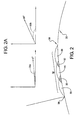
- FIG. 2 a side view of a series of ink droplets 30 with overlapping portions 32 that exhibit a contiguous area of ink 34. Viewed in cross section, the contiguous area of ink extends from a first drop edge 36 to a second drop edge 38.
- the contact angles (or angles of the edges) for the droplets of ink which are represented by ink droplets 30a and 30b in the figure, range from about 5 degrees to about 25 degrees. Moreover, in a particular embodiment, the contact angles may range between about 12 to about 15 degrees.
- the individual ink drops can comprise various known colors, including for instance, primary printing colors such as cyan, magenta, and yellow. Moreover, controlling the overlapping or combinations of certain colors in overlapping areas, such as overlapped portions 32 can provide additional "process" colors. Additionally, the ink droplets may be curable. For example, UV curable ink droplets may comprise all or a portion of the digital image.
- Individual ink droplets 30, including those associated with a single digital image vary in diameter D from about 10 microns to about 200 microns.
- the diameter D of the droplets can range from about 30 microns to about 90 microns.
- the application of ink drops provided on a base coat on the surface of the container to form the digital images ranges from about 200 to about 1200 drops per inch (DPI) and, in an embodiment, may range from 300 to 1200 DPI.
- DPI drops per inch
- the resulting digital image formed on a container surface may, for example and without limitation, take the form of a label and may include various text and/or graphics, including color text and graphics.
- FIG. 3 An ink droplet application system 40 according to an embodiment of the invention is shown in FIG. 3 .
- a plurality of containers which may include a non-planar (e.g., oval, round, or simply generally curved) surface 20, may be transported or conveyed past a printing subsystem 50.
- the printing subsystem may comprise one or more print heads 60; at least one actuator 70 for controlling the up-down position of the print head or heads relative to the containers; an ink delivery device 62 for delivering one or more types or colors of ink to one or more print heads; and a temperature control device 64, which serves to at least in part regulate or control the temperature of the ink, and may include a plurality of fluid lines 66.
- the temperature control device may include fluid heating units and one or more pumps that circulate heated water or other fluid. If desired, the fluid may be circulated in a closed circuit.
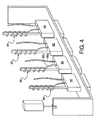
- FIG. 4 illustrates an embodiment of the system 40 in which individual print heads 60 are supplied with ink through ink lines 65 and include, for instance, a plurality of water lines.
- the water lines may comprise a circuit and include input lines 66a and supply return lines 66b.
- the water lines e.g., return lines 66b
- the fluid lines such as the illustrated water lines 66b, may be wrapped around the ink lines 65 from the ink source to the print heads.
- the flow of fluid could be reversed, and the inlet fluid lines could be lines 66b and the output fluid lines could be 66a. In either case, such fluid lines help to maintain the ink at a desired temperature throughout the system while associated print heads move up and down.
- the ink can be maintained at a temperature or a desired temperature range within the print heads for delivery of ink droplets to the surface of the container to be treated.
- the ink is maintained at a temperature in the print heads (i.e., just prior to dispersion or application) from about 40°C to about 50°C.
- the containers 10 are generally shown being transported by a conveyor. However, it is important to note that the invention is not limited to such a means of conveyance. Rather, the containers may be transported past the printing subsystem 50 in other manners and using other container handling techniques provided the surface that is to be printed upon is not operatively obstructed from the print heads 60 and the position of the surface that is to be printed upon can be sufficiently established in space with respect to the printing subsystem so that the print heads can be positioned to maintain a controlled distance from the surface. For example, without limitation, the containers may be temporarily retained in a fixture or holder that moves past the print heads.
- the application system 40 may additionally include a scanning device 80, such as a laser scanner.
- the scanning device 80 can be used to scan each container surface that is to be printed upon prior to moving the container through the printing subsystem 50.
- the scanning device 80 can capture surface profile data for the surface of the container to be printed, including, for example, surface variability and curvature data.
- the scanned surface data is communicated to a signal conditioner 82, which may condition the data and communicate the data or conditioned data to a processor 84.
- the processor 84 processes the information and provides motion control signals to a motion controller 86, which in turn can provide control signals to the actuator 70 for positioning one or more print heads 60 at a given point in time (relative to and coordinated with the surface of the container being moved).
- the system 40 is not limited to one having a separate and distinct scanning device, signal conditioner, processor, motion controller, and/or actuator. Rather, such components may be provided in various combinations or have their functions combined in various operative combinations without departing from the scope of the present invention.
- the scanning device may develop container surface data, communicate the data, whether directly or indirectly, to the print heads (or the actuator or controller controlling the position of the print heads), and the distance between the print heads and the container surface to be printed can be controlled while the container moves past the print heads.
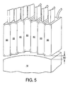
- the printing subsystem controls the position of the print heads 60 and, for a non-planar surface, can effectively maintain a defined or controlled offset with respect to the surface of the container.
- the system 40 can be configured to maintain a 1 mm ⁇ 0.3 mm standoff distance SD between the portion of the print head dispensing ink and the surface of the container that receives the droplets of ink.
- the standoff distance SD may be said to particularly pertain to the distance between the portion of the print head 60 that provides the ink (at the time the ink is applied) and the surface of the container that receives the ink droplets.
- portions of a print head 60 that do not coincide to the portions of the print head that apply the ink may encroach the space associated with the standoff distance SD , provided, however, that such encroachment should not create a physical interference between a print head and a container.
- the containers are moved at a constant or substantially constant velocity past the print heads.
- embodiments of the system can include sensors that determine, monitor, and/or control the speed of movement (i.e., the velocity V) of the containers at one or more stages in the system.
- the system 40 can, for example, provide such information to a processor or controller, and coordinate the movement of the print heads to adjust for the constant or non-constant movement of the containers past the print heads.
- one or more feedback control systems can be incorporated into the system to serve such a control function and coordinate the position and movement of the print heads relative to a container that is moving past the print head.
- the containers may be pre-treated prior to entering the printing subsystem 50 or passing a print head.
- Pre-treatment can be used, for instance, to increase the surface temperature of a container to provide improved bonding with the droplets of ink.
- Some known pre-treating techniques include, without limitation, flame, corona, and plasma treatment. However, the invention is not limited to those pre-treatment options.
- FIG. 6 generally shows a side view of droplet of ink 30 applied to a base coat 90.
- the contact angle (or angle of the edge) for the droplets is generally identified by arrow 92a; the contact angle for the base coat is shown generally identified by arrow 92b.
- the contact angles associated with the droplets of ink and/or the base coat may be between about 5 degrees to about 25 degrees and, for some applications, one or both may be between about 12 and about 15 degrees.
- the base coat may be comprised of material that serves to improve the application of ink droplets and/or provides a visual characteristic.
- all or a portion of the base coat may be digitally printed on at least a portion of a surface of the container.
- one or more digital images are printed entirely on a base coat.
- a portion of the base coat and/or a portion of the surface of the container may form a portion of the digital image.
- the printing subsystem can be programmed to controllably avoid dispersion of droplets of ink over such portions.
- the system 40 may further include a means for curing droplets of ink associated with the digital image.
- the means for curing may include one or more UV lamps 100.
- the digital images printed on the surface of the container may be prescribed to be cured within a defined period. For example, in an embodiment, the digital images are cured between 0.5 seconds and 5 seconds after the ink droplets contact the container surface.
- the application system 40 may also include a post-printing scanner (not shown) that scans the final digital image. The system can then evaluate the post-printing data to assess whether or not the image printed on a given container meets a prescribed or established criteria, which may generally correlate to the quality of the image. If the image printed on the container does not meet the prescribed or established criteria, a communication may be initiated (such as an alarm or notification to an operator) and the container may be routed to an area for further assessment and disposal or rework.
- a post-printing scanner not shown
Description
- This application claims the benefit of United States Patent Application No.
11/562,655, filed 22 November 2006 - The present invention relates generally to plastic containers having digital images printed thereon, particularly containers with curved surfaces, and methods for printing images on plastic containers.
- Conventional techniques for printing onto curved surface plastic containers are subject to certain limitations and drawbacks. Such techniques make it difficult to provide a container, particularly a container having a non-planar surface, with an image that is commercially acceptable. A further challenge, is to efficiently provide a container with a multi-color digital image printed at acceptable speeds and at a reasonable cost.
- The
US 2006/0144261 A1 discloses a plastic container comprising a container having a non-planar external surface with a digital image printed thereon by droplets of ink. - Furthermore the
US2006/250464 A1 discloses a method and apparatus for printing selected information on bottles, by: conveying the bottles sequentially through a predetermined path including at least one printing station; actuating an ink-jet print head at the printing station to discharge liquid ink droplets onto the bottle in the printing station; and controlling the print head at the printing station to discharge the liquid ink droplets onto the bottle in accordance with the selected information to be printed thereon. - The present invention provides for the printing of one or more digital images on a container having a non-planar external surface. The digital image is printed on the container by application of ink droplets. The ink droplets vary in diameter from 10 to 200 microns and the droplets range from 200 to 1200 drops per inch. Methods for digital printing plastic containers are also disclosed.
- Embodiments of the invention will now be described, by way of example, with reference to the accompanying drawings, wherein:
-
FIG. 1 is a top perspective view illustrating a pattern of ink droplets applied to a non-planar surface of a container according to an embodiment of the invention; -
FIG. 2 is a side view of a series of ink droplets with overlapping portions; -
FIG. 2A is a side view of an ink droplet illustrating associated angular measurements. -
FIG. 3 is a graphical representation of an ink droplet application system according to an embodiment of the invention; -
FIG. 4 is a graphical representation of a portion of a printing subsystem in accordance with an embodiment of the invention; -
FIG. 5 is a graphical representation of a printing subsystem according to an embodiment of the invention; and -
FIG. 6 is a side view of droplets of ink applied to a base coat. - Reference will now be made in detail to embodiments of the present invention, examples of which are described herein and illustrated in the accompanying drawings. While the invention will be described in conjunction with embodiments, it will be understood that they are not intended to limit the invention to these embodiments.
- A portion of a
container 10 having anon-planar surface 20 is generally illustrated inFIG. 1 . A plurality of droplets of ink (or ink droplets) 30, are shown disbursed upon thesurface 20 of the container. The droplets ofink 30 collectively may form part of an application pattern which, in turn, may form all or a portion of a predefined digital image. The application pattern may comprise a grid-type pattern, such as the grid pattern shown or, alternatively, may take on other forms of controlled or defined application patterns. Further, as generally illustrated, portions of one or moreadjacent ink droplets 30 may overlap or intermix with each another, forming overlappedportions 32. -
FIG. 2 a side view of a series ofink droplets 30 with overlappingportions 32 that exhibit a contiguous area ofink 34. Viewed in cross section, the contiguous area of ink extends from afirst drop edge 36 to asecond drop edge 38. As perhaps better illustrated inFIG. 2A , in an embodiment, the contact angles (or angles of the edges) for the droplets of ink, which are represented byink droplets - Depending upon the desired digital image or images, the individual ink drops can comprise various known colors, including for instance, primary printing colors such as cyan, magenta, and yellow. Moreover, controlling the overlapping or combinations of certain colors in overlapping areas, such as overlapped
portions 32 can provide additional "process" colors. Additionally, the ink droplets may be curable. For example, UV curable ink droplets may comprise all or a portion of the digital image. -
Individual ink droplets 30, including those associated with a single digital image, vary in diameter D from about 10 microns to about 200 microns. In a particular embodiment, the diameter D of the droplets can range from about 30 microns to about 90 microns. Additionally, the application of ink drops provided on a base coat on the surface of the container to form the digital images ranges from about 200 to about 1200 drops per inch (DPI) and, in an embodiment, may range from 300 to 1200 DPI. The resulting digital image formed on a container surface may, for example and without limitation, take the form of a label and may include various text and/or graphics, including color text and graphics. - An ink
droplet application system 40 according to an embodiment of the invention is shown inFIG. 3 . As generally illustrated, a plurality ofcontainers 10, which may include a non-planar (e.g., oval, round, or simply generally curved)surface 20, may be transported or conveyed past aprinting subsystem 50. The printing subsystem may comprise one ormore print heads 60; at least oneactuator 70 for controlling the up-down position of the print head or heads relative to the containers; anink delivery device 62 for delivering one or more types or colors of ink to one or more print heads; and atemperature control device 64, which serves to at least in part regulate or control the temperature of the ink, and may include a plurality offluid lines 66. - In an embodiment, the temperature control device may include fluid heating units and one or more pumps that circulate heated water or other fluid. If desired, the fluid may be circulated in a closed circuit.
FIG. 4 illustrates an embodiment of thesystem 40 in whichindividual print heads 60 are supplied with ink through ink lines 65 and include, for instance, a plurality of water lines. The water lines may comprise a circuit and includeinput lines 66a and supplyreturn lines 66b. In an embodiment, the water lines (e.g.,return lines 66b) may be wrapped around ink lines 65. If desired, the fluid lines, such as the illustratedwater lines 66b, may be wrapped around the ink lines 65 from the ink source to the print heads. Alternatively, the flow of fluid could be reversed, and the inlet fluid lines could belines 66b and the output fluid lines could be 66a. In either case, such fluid lines help to maintain the ink at a desired temperature throughout the system while associated print heads move up and down. - The ink can be maintained at a temperature or a desired temperature range within the print heads for delivery of ink droplets to the surface of the container to be treated. In an embodiment of the invention, the ink is maintained at a temperature in the print heads (i.e., just prior to dispersion or application) from about 40°C to about 50°C.
- In
FIG. 3 , thecontainers 10 are generally shown being transported by a conveyor. However, it is important to note that the invention is not limited to such a means of conveyance. Rather, the containers may be transported past theprinting subsystem 50 in other manners and using other container handling techniques provided the surface that is to be printed upon is not operatively obstructed from theprint heads 60 and the position of the surface that is to be printed upon can be sufficiently established in space with respect to the printing subsystem so that the print heads can be positioned to maintain a controlled distance from the surface. For example, without limitation, the containers may be temporarily retained in a fixture or holder that moves past the print heads. - The
application system 40 may additionally include ascanning device 80, such as a laser scanner. Thescanning device 80 can be used to scan each container surface that is to be printed upon prior to moving the container through theprinting subsystem 50. Thescanning device 80 can capture surface profile data for the surface of the container to be printed, including, for example, surface variability and curvature data. In an embodiment, the scanned surface data is communicated to asignal conditioner 82, which may condition the data and communicate the data or conditioned data to aprocessor 84. Theprocessor 84 processes the information and provides motion control signals to amotion controller 86, which in turn can provide control signals to theactuator 70 for positioning one or more print heads 60 at a given point in time (relative to and coordinated with the surface of the container being moved). - It is important to note that the
system 40 is not limited to one having a separate and distinct scanning device, signal conditioner, processor, motion controller, and/or actuator. Rather, such components may be provided in various combinations or have their functions combined in various operative combinations without departing from the scope of the present invention. For example, in a simplified embodiment, the scanning device may develop container surface data, communicate the data, whether directly or indirectly, to the print heads (or the actuator or controller controlling the position of the print heads), and the distance between the print heads and the container surface to be printed can be controlled while the container moves past the print heads. - The printing subsystem controls the position of the print heads 60 and, for a non-planar surface, can effectively maintain a defined or controlled offset with respect to the surface of the container. For example, as generally illustrated in the embodiment of the system shown in
FIG. 5 , thesystem 40 can be configured to maintain a 1 mm ± 0.3 mm standoff distance SD between the portion of the print head dispensing ink and the surface of the container that receives the droplets of ink. It is worthwhile to note that, for embodiments of the invention, the standoff distance SD may be said to particularly pertain to the distance between the portion of theprint head 60 that provides the ink (at the time the ink is applied) and the surface of the container that receives the ink droplets. That is, portions of aprint head 60 that do not coincide to the portions of the print head that apply the ink may encroach the space associated with the standoff distance SD, provided, however, that such encroachment should not create a physical interference between a print head and a container. - With further reference to
FIG. 3 , in an embodiment of thesystem 40, the containers are moved at a constant or substantially constant velocity past the print heads. However, embodiments of the system can include sensors that determine, monitor, and/or control the speed of movement (i.e., the velocity V) of the containers at one or more stages in the system. Thesystem 40 can, for example, provide such information to a processor or controller, and coordinate the movement of the print heads to adjust for the constant or non-constant movement of the containers past the print heads. Moreover, one or more feedback control systems can be incorporated into the system to serve such a control function and coordinate the position and movement of the print heads relative to a container that is moving past the print head. - For some applications, the containers may be pre-treated prior to entering the
printing subsystem 50 or passing a print head. Pre-treatment can be used, for instance, to increase the surface temperature of a container to provide improved bonding with the droplets of ink. Some known pre-treating techniques include, without limitation, flame, corona, and plasma treatment. However, the invention is not limited to those pre-treatment options. - Additionally, the
system 40 provides for the application of a base coat to a portion of the surface of a container prior to printing a digital image. For example,FIG. 6 generally shows a side view of droplet ofink 30 applied to abase coat 90. In the figure, the contact angle (or angle of the edge) for the droplets is generally identified byarrow 92a; the contact angle for the base coat is shown generally identified byarrow 92b. In an embodiment, the contact angles associated with the droplets of ink and/or the base coat may be between about 5 degrees to about 25 degrees and, for some applications, one or both may be between about 12 and about 15 degrees. The base coat may be comprised of material that serves to improve the application of ink droplets and/or provides a visual characteristic. If desired all or a portion of the base coat may be digitally printed on at least a portion of a surface of the container. In an embodiment of the invention, one or more digital images are printed entirely on a base coat. Further, for some applications, a portion of the base coat and/or a portion of the surface of the container may form a portion of the digital image. For example, if a portion of the intended digital image includes a color that sufficiently matches that of the surface of the container or the base coat, the printing subsystem can be programmed to controllably avoid dispersion of droplets of ink over such portions. - Referring again to
FIG. 3 , thesystem 40 may further include a means for curing droplets of ink associated with the digital image. For example, if UV curable inks are applied, the means for curing may include one ormore UV lamps 100. Moreover, the digital images printed on the surface of the container may be prescribed to be cured within a defined period. For example, in an embodiment, the digital images are cured between 0.5 seconds and 5 seconds after the ink droplets contact the container surface. - The
application system 40 may also include a post-printing scanner (not shown) that scans the final digital image. The system can then evaluate the post-printing data to assess whether or not the image printed on a given container meets a prescribed or established criteria, which may generally correlate to the quality of the image. If the image printed on the container does not meet the prescribed or established criteria, a communication may be initiated (such as an alarm or notification to an operator) and the container may be routed to an area for further assessment and disposal or rework. - The foregoing descriptions of specific embodiments of the present invention have been presented for purposes of illustration and description. They are not intended to be exhaustive or to limit the invention to the precise forms disclosed, and various modifications and variations are possible in light of the above teaching. The embodiments were chosen and described in order to explain the principles of the invention and its practical application, to thereby enable others skilled in the art to utilize the invention and various embodiments with various modifications as are suited to the particular use contemplated. It is intended that the scope of the invention be defined by the claims appended hereto.
Claims (26)
- A plastic container comprising a container (10) having a non-planar external surface (20),
characterized in
that the container includes a base coat, which is a digitally printed base coat and wherein a digital image is printed on at least a portion of the base coat, the digital image being printed thereon by droplets of ink (30), wherein the ink droplets (30), which form the digital image, vary in diameter from 10 to 200 microns and wherein the droplets of ink (30) range from 200 to 1200 drops per inch. - A container (10) according to claim 1, wherein the droplets of ink (30) vary in diameter from 30 to 90 microns.
- A container (10) according to claim 1, wherein the droplets of ink (30) range from 300 to 1200 drops per inch.
- A container (10) according to claim 1, wherein the droplets of ink (30) are spread out on the container surface and portions of droplets (30) overlap with adjoining droplets (32).
- A container (10) according to claim 1, wherein the droplets of ink (30) are provided in a grid pattern, which is defined by a calculated or anticipated droplet disbursement.
- A container (10) according to claim 1, wherein the angle of the edges (36, 38) of the droplets of ink (30a, 30b) is from about 5 to about 25 degrees.
- A container (10) according to claim 1, wherein the angle of the edges (36, 38) of the droplets of ink (30a, 30b) is from about 12 to about 15 degrees.
- A container (10) according to claim 1, wherein the digital images have multiple colors, wherein portions of adjacent droplets of ink (30) overlap to provide one or more process colors, and wherein at least a portion of the droplets of ink (30) are UV curable, and wherein the droplets of ink (30) define a pre-determined image on the container surface.
- A container (10) according to claim 1, wherein the entire digital image is printed on the base coat.
- A container (10) according to claim 1, wherein a portion of the base coat forms a portion of the digital image.
- A container (10) according to claim 1, wherein a portion of the surface of the container provides a portion of the color forming part of the digital image, and wherein the container external surface is a curved external surface (20).
- A method (40) for printing digital images on plastic containers (10), comprising: providing a hollow plastic container (10) having a non-planar external surface (20); moving the container (10) along a track past a digital printing location (50) having a plurality of movable print heads (60) that provide droplets of ink (30), characterized by including the step of applying a base coat (90) on the container (10) prior to printing the digital image, wherein the digital image is provided on at least a portion of the base coat (90), wherein the base coat (90) is printed on the container (10), wherein the droplets of ink (30), which form the digital image, have a diameter from 10 to 200 microns and the droplets of ink ranging from 200 to 1200 drops per inch; and printing a digital image on the non-planar container surface (20) by applying the droplets of ink (30) to the base coat (90) on the container surface (20).
- A method (40) according to claim 12, wherein the droplets of ink (30) are applied to the container surface (20) while the container is moving, and wherein a plurality of containers (10) are provided in series.
- A method (40) according to claim 12, including scanning the container surface (20) prior to moving the container past the digital printing location, wherein the scanning develops container surface data, the container surface data is communicated to the print heads (60), and at least a portion of the communicated data is used to control the distance between a portion of the print heads (60) and the container surface (20) to be printed, and wherein the container surface data includes surface curvature data.
- A method (40) according to claim 12, wherein during the printing process, the print heads (60) are moved to maintain a substantially constant distance between a portion of the print heads dispensing ink and the container surface (20) to be printed.
- A method (40) according to claim 12, wherein during the printing process, the print heads (60) are moved to maintain a 1 mm 0.3 mm standoff distance (SD) between a portion of the print heads (10) dispensing ink and the container surface (20) to be printed.
- A method (40) according to claim 12, wherein the ink is maintained in the print heads (60) at a temperature of about 40° C to about 50° C for application of the droplets of ink (30), and wherein the container external surface (20) is a curved external surface and is scanned by laser scanning (80).
- A method (40) according to claim 12, wherein the containers (10) are moved at a constant velocity (V).
- A method (40) according to claim 12, wherein the containers (10) are moved at a non-constant velocity, the velocity (V) of the containers (10) is measured and communicated to the print heads (60), and the movement of the print heads (60) and application of droplets of ink (30) is coordinated with respect to the measured velocity (V).
- A method (40) according to claim 12, wherein the printed digital image is cured after printing, and wherein the image is printed by UV curable ink, and wherein the printed image is cured by UV light.
- A method (40) according to claim 20, wherein the image is cured 0.5 seconds to 5 seconds after droplets of ink (30) contact the container surface (20).
- A method (40) according to claim 12, wherein the droplets of ink (30) spread out on the container surface (20) and at least a portion of the droplets of ink overlap with adjoining droplets (32).
- A method (40) according to claim 12, wherein the angle (92a) of the edges of the droplets of ink ranges from about 5 degrees to about 25 degrees.
- A method (40) according to claim 12, wherein the angle (92a) of the edges of the droplets of ink ranges from about 12 degrees to about 15 degrees.
- A method (40) according to claim 12, wherein the digital images have multiple colors, and wherein individual droplets of ink (30) have varying diameters.
- A method (40) according to claim 12, including pre-treating the container (10) prior to applying the base coat (90), and including scanning the digital image following printing to determine if the digital image meets established criteria.
Priority Applications (3)
| Application Number | Priority Date | Filing Date | Title |
|---|---|---|---|
| PL07864674T PL2089234T3 (en) | 2006-11-22 | 2007-11-20 | Digital printing plastic containers |
| SI200731613T SI2089234T1 (en) | 2006-11-22 | 2007-11-20 | Digital printing plastic containers |
| CY20151100235T CY1116380T1 (en) | 2006-11-22 | 2015-03-06 | DIGITAL PRINTING OF PLASTIC RECEPTORS |
Applications Claiming Priority (2)
| Application Number | Priority Date | Filing Date | Title |
|---|---|---|---|
| US11/562,655 US7625059B2 (en) | 2006-11-22 | 2006-11-22 | Digital printing plastic containers |
| PCT/US2007/085279 WO2008064248A2 (en) | 2006-11-22 | 2007-11-20 | Digital printing plastic containers |
Publications (3)
| Publication Number | Publication Date |
|---|---|
| EP2089234A2 EP2089234A2 (en) | 2009-08-19 |
| EP2089234A4 EP2089234A4 (en) | 2010-10-06 |
| EP2089234B1 true EP2089234B1 (en) | 2014-12-17 |
Family
ID=39416498
Family Applications (1)
| Application Number | Title | Priority Date | Filing Date |
|---|---|---|---|
| EP07864674.2A Revoked EP2089234B1 (en) | 2006-11-22 | 2007-11-20 | Digital printing plastic containers |
Country Status (21)
| Country | Link |
|---|---|
| US (2) | US7625059B2 (en) |
| EP (1) | EP2089234B1 (en) |
| JP (2) | JP6143997B2 (en) |
| KR (1) | KR101465539B1 (en) |
| CN (2) | CN103693259A (en) |
| AU (1) | AU2007323638B2 (en) |
| BR (1) | BRPI0717678B1 (en) |
| CA (1) | CA2668660A1 (en) |
| CY (1) | CY1116380T1 (en) |
| DK (1) | DK2089234T3 (en) |
| ES (1) | ES2527879T3 (en) |
| HU (1) | HUE024577T2 (en) |
| IL (1) | IL198674A (en) |
| MX (1) | MX2009005321A (en) |
| MY (2) | MY149368A (en) |
| PL (1) | PL2089234T3 (en) |
| PT (1) | PT2089234E (en) |
| RU (1) | RU2415023C2 (en) |
| SI (1) | SI2089234T1 (en) |
| UA (1) | UA99268C2 (en) |
| WO (1) | WO2008064248A2 (en) |
Cited By (2)
| Publication number | Priority date | Publication date | Assignee | Title |
|---|---|---|---|---|
| WO2019042600A1 (en) | 2017-09-04 | 2019-03-07 | Krones Ag | Direct printer for applying a printed layer to containers |
| DE102018212623A1 (en) * | 2018-07-27 | 2020-01-30 | Krones Ag | Process for applying a functional layer to a container |
Families Citing this family (44)
| Publication number | Priority date | Publication date | Assignee | Title |
|---|---|---|---|---|
| US9272815B2 (en) | 2006-05-09 | 2016-03-01 | Plastipak Packaging, Inc. | Digital printing plastic container |
| PL2303587T3 (en) | 2008-06-24 | 2013-02-28 | Plastipak Packaging Inc | Apparatus and method for printing on articles having a non-planar surface |
| US8876979B2 (en) | 2008-10-20 | 2014-11-04 | Plastipak Packaging, Inc. | Recyclable printed plastic container and method |
| BRPI0920149A2 (en) * | 2008-10-20 | 2015-12-22 | Plastipak Packaging Inc | recyclable plastic packing |
| US10400118B2 (en) | 2008-10-20 | 2019-09-03 | Plastipak Packaging, Inc. | Methods and compositions for direct print having improved recyclability |
| DE102009061258B3 (en) * | 2009-05-19 | 2018-10-18 | Pas Deutschland Gmbh | Method for printing on a non-planar surface, and aperture arrangement and household appliance |
| JP2012527387A (en) * | 2009-05-21 | 2012-11-08 | インクス インターナショナル インク カンパニー | Apparatus and associated method for printing on an object having a generally cylindrical shape |
| US20110132916A1 (en) * | 2009-12-03 | 2011-06-09 | Plastipak Packaging, Inc. | Container with non-cylindrical upper body portion |
| EP2595810B1 (en) | 2010-07-23 | 2018-08-22 | Plastipak Packaging, Inc. | Rotary system and method for printing containers |
| DE102011007979A1 (en) * | 2011-01-05 | 2012-07-05 | Till Gmbh | Machine for printing on containers |
| DE102011009391A1 (en) † | 2011-01-25 | 2012-07-26 | Krones Aktiengesellschaft | Apparatus and method for printing on containers |
| TW201231169A (en) * | 2011-01-27 | 2012-08-01 | Asustek Comp Inc | Casing printing method and printing apparatus thereof |
| CN103874581A (en) * | 2011-08-31 | 2014-06-18 | 普拉斯蒂派克包装公司 | Method and system for personalized digital printing |
| DE102011086015A1 (en) * | 2011-11-09 | 2013-05-16 | Krones Aktiengesellschaft | Method and apparatus for ink jet printing on curved object surfaces |
| WO2013170037A1 (en) * | 2012-05-09 | 2013-11-14 | Plastipak Packaging, Inc. | Digital printing plastic container |
| KR101390391B1 (en) * | 2012-05-21 | 2014-05-27 | 엔젯 주식회사 | Apparatus for printing on 3-dimensional surface using electrohydrodynamic force |
| DE102012209305A1 (en) | 2012-06-01 | 2013-12-05 | Krones Ag | Method and device for controlling or correcting direct pressure on containers with relief-like surface contour |
| CA2878153C (en) | 2012-08-27 | 2020-09-22 | Agfa Graphics Nv | Recycling of radiation cured printed matter |
| US9770922B2 (en) | 2012-11-15 | 2017-09-26 | Velox-Puredigital Ltd. | Printing system and method |
| DE102014100392A1 (en) * | 2014-01-15 | 2015-07-16 | Krones Ag | Container treatment machine for printing on containers |
| DE102014012395A1 (en) * | 2014-08-21 | 2016-02-25 | Heidelberger Druckmaschinen Ag | Method and apparatus for printing a curved surface of an object with an ink jet head |
| CN107073992A (en) | 2014-11-13 | 2017-08-18 | 宝洁公司 | Digital printing and the product of decoration |
| US10252544B2 (en) | 2014-11-13 | 2019-04-09 | The Procter & Gamble Company | Apparatus and method for depositing a substance on articles |
| CN107107638A (en) | 2014-11-13 | 2017-08-29 | 宝洁公司 | The product of digital printing |
| MX2017006260A (en) | 2014-11-13 | 2017-07-31 | Procter & Gamble | Process for decorating an article. |
| FR3033506B1 (en) | 2015-03-11 | 2020-02-21 | Reydel Automotive B.V. | METHOD AND INSTALLATION FOR COATING A BODY WITH THE FORMATION OF A STRUCTURED SURFACE |
| WO2017040096A1 (en) | 2015-08-31 | 2017-03-09 | The Procter & Gamble Company | Parallel motion method for depositing a substance on articles |
| KR20170033084A (en) | 2015-09-16 | 2017-03-24 | 동우 화인켐 주식회사 | Polarizing plate with united prism sheet and image display comprising the same |
| CN108472971A (en) | 2015-12-28 | 2018-08-31 | 宝洁公司 | Three-dimensional article with material for transfer thereon |
| WO2017116669A1 (en) | 2015-12-28 | 2017-07-06 | The Procter & Gamble Company | Method and apparatus for applying a material onto articles using a transfer component that deflects on both sides |
| WO2017116671A1 (en) | 2015-12-28 | 2017-07-06 | The Procter & Gamble Company | Method for transferring material with adhesive onto articles with a difference in degree of curing between the material and adhesive |
| US11141995B2 (en) | 2015-12-28 | 2021-10-12 | The Procter & Gamble Company | Method and apparatus for applying a material onto articles with a pre-distorted transfer component |
| US10682837B2 (en) | 2017-06-09 | 2020-06-16 | The Proctor & Gamble Company | Method and compositions for applying a material onto articles |
| US20180354253A1 (en) | 2017-06-09 | 2018-12-13 | The Procter & Gamble Company | Method for Applying Material onto and Conforming to Three-Dimensional Articles |
| WO2019099183A1 (en) | 2017-11-17 | 2019-05-23 | The Procter & Gamble Company | Methods for applying a material onto articles |
| EP3564042A3 (en) | 2018-05-01 | 2020-01-22 | The Procter & Gamble Company | Methods for applying a reflective material onto articles, and articles with reflective material thereon |
| CN110435318B (en) * | 2018-05-02 | 2020-11-10 | 温州酷乐餐桌用品有限公司 | Spherical curved surface printing process |
| US10960698B2 (en) * | 2018-12-20 | 2021-03-30 | Xerox Corporation | Systems and methods for printing of removable and permanent images on an object |
| EP3696107A1 (en) | 2019-02-12 | 2020-08-19 | The Procter & Gamble Company | Method for applying a material onto articles using a transfer component |
| DE102019110564A1 (en) * | 2019-04-24 | 2020-10-29 | Dr. Ing. H.C. F. Porsche Aktiengesellschaft | Method and device for printing on a body |
| US11752792B2 (en) | 2020-03-09 | 2023-09-12 | The Procter & Gamble Company | Method and apparatus for applying a material onto articles using a transfer component |
| CN113022134A (en) * | 2021-03-10 | 2021-06-25 | 浙江普崎数码科技有限公司 | Three-dimensional relief layered ink-jet printer and layered printing method thereof |
| JP2023035380A (en) * | 2021-09-01 | 2023-03-13 | セイコーエプソン株式会社 | Three-dimensional object printing apparatus |
| DE102021131754A1 (en) | 2021-12-02 | 2023-06-07 | Krones Aktiengesellschaft | Process and device for printing containers |
Family Cites Families (36)
| Publication number | Priority date | Publication date | Assignee | Title |
|---|---|---|---|---|
| US2999190A (en) * | 1957-03-11 | 1961-09-05 | Gen Electric | Switchboard |
| US3417175A (en) * | 1965-07-15 | 1968-12-17 | Kaumagraph Co | Method for relief decorating plastic molded articles |
| US3490363A (en) | 1967-05-03 | 1970-01-20 | Charles H Derrickson | Screen printing of flexible bottles of square cross section |
| JPS4910846B1 (en) * | 1969-11-29 | 1974-03-13 | ||
| US3999190A (en) * | 1975-10-22 | 1976-12-21 | Burroughs Corporation | Temperature control system for ink jet printer |
| US4519310A (en) * | 1981-04-27 | 1985-05-28 | Daiwa Can Company, Limited | Method of multi-color printing on cylindrical container |
| US5011862A (en) * | 1988-07-29 | 1991-04-30 | Pierce & Stevens Corporation | Coating media containing low density composite opacifiers |
| US5182571A (en) * | 1990-02-26 | 1993-01-26 | Spectra, Inc. | Hot melt ink jet transparency |
| US5858514A (en) * | 1994-08-17 | 1999-01-12 | Triton Digital Imaging Systems, Inc. | Coatings for vinyl and canvas particularly permitting ink-jet printing |
| CN1209770A (en) * | 1996-01-26 | 1999-03-03 | 利乐拉瓦尔集团及财务有限公司 | Method and apparatus for printing images on packing material |
| DE19603906A1 (en) * | 1996-02-03 | 1997-08-07 | Wella Ag | Bottle-like plastic container and process for its manufacture |
| US5753325A (en) * | 1996-06-13 | 1998-05-19 | Mcdaniel; Harry C. | Articles having scuff resistant lustrous coatings |
| US6002844A (en) * | 1996-08-09 | 1999-12-14 | Canon Aptex Inc. | Barcode printing system and its control method |
| US5984456A (en) * | 1996-12-05 | 1999-11-16 | Array Printers Ab | Direct printing method utilizing dot deflection and a printhead structure for accomplishing the method |
| GB9717776D0 (en) * | 1997-08-21 | 1997-10-29 | Procter & Gamble | Printing process and apparatus |
| EP1231172A1 (en) | 1997-09-04 | 2002-08-14 | Xaar Technology Limited | Vacuum drums for printing and duplex printers |
| US6409294B1 (en) * | 1997-12-21 | 2002-06-25 | Ascom Hasler Mailing Systems Ag | Digital postage franking with coherent light velocimetry |
| JPH11320894A (en) * | 1998-05-13 | 1999-11-24 | Matsushita Electric Ind Co Ltd | Ink jet head |
| GB9828476D0 (en) | 1998-12-24 | 1999-02-17 | Xaar Technology Ltd | Apparatus for depositing droplets of fluid |
| US6406115B2 (en) * | 1999-01-19 | 2002-06-18 | Xerox Corporation | Method of printing with multiple sized drop ejectors on a single printhead |
| JP4582844B2 (en) * | 1999-12-13 | 2010-11-17 | 京セラ株式会社 | Inkjet head |
| DE10019926A1 (en) | 2000-04-20 | 2001-10-31 | Isimat Gmbh Siebdruckmaschinen | Method for modifying a surface of a compact substrate |
| JP2002166637A (en) * | 2000-12-01 | 2002-06-11 | Takeuchi Press Ind Co Ltd | Method for manufacturing metal container printed with foamable ink |
| US6478398B2 (en) * | 2001-01-08 | 2002-11-12 | Xerox Corporation | Ink jet printer having a printhead assembly for recording high quality graphic images and photo quality images |
| US20020097280A1 (en) | 2001-01-25 | 2002-07-25 | Bertram Loper | Apparatus and method of printing on a curved surface with an ink jet printer |
| US6706342B2 (en) * | 2001-02-21 | 2004-03-16 | Exxonmobil Oil Corporation | Polymeric labels |
| GB2376920A (en) | 2001-06-27 | 2002-12-31 | Inca Digital Printers Ltd | Inkjet printing on a three-dimensional object including relative movement of a printhead and the object during printing about a rotational axis |
| GB0121909D0 (en) | 2001-09-11 | 2001-10-31 | Xaar Technology Ltd | Droplet deposition apparatus |
| ATE365110T1 (en) | 2002-11-13 | 2007-07-15 | Kodak Il Ltd | USING A CONTINUOUS INKJET PRINTER FOR PRECISE PRINTING WITH TITANIUM OXIDE BASED INK |
| EP1479715A1 (en) * | 2003-05-15 | 2004-11-24 | Fuji Photo Film B.V. | Microporous film |
| US6769357B1 (en) | 2003-06-05 | 2004-08-03 | Sequa Can Machinery, Inc. | Digital can decorating apparatus |
| WO2005025873A2 (en) | 2003-09-17 | 2005-03-24 | Jemtex Ink Jet Printing Ltd. | Method and apparatus for printing selected information on bottles |
| DE602004022192D1 (en) | 2003-11-12 | 2009-09-03 | Vutek Inc | RADIATION-HARDENED INK COMPOSITIONS AND APPLICATIONS THEREFOR |
| US7168472B2 (en) * | 2004-03-03 | 2007-01-30 | Sinclair Systems International, Llc | Method and apparatus for applying variable coded labels to items of produce |
| DE602004019436D1 (en) * | 2004-12-16 | 2009-03-26 | Agfa Graphics Nv | A method of ink-jet printing with radiation-curable ink, wherein a liquid is used to control dot size |
| US7210408B2 (en) * | 2004-12-30 | 2007-05-01 | Plastipak Packaging, Inc. | Printing plastic containers with digital images |
-
2006
- 2006-11-22 US US11/562,655 patent/US7625059B2/en active Active
-
2007
- 2007-11-20 MX MX2009005321A patent/MX2009005321A/en active IP Right Grant
- 2007-11-20 AU AU2007323638A patent/AU2007323638B2/en not_active Ceased
- 2007-11-20 MY MYPI20091891A patent/MY149368A/en unknown
- 2007-11-20 WO PCT/US2007/085279 patent/WO2008064248A2/en active Application Filing
- 2007-11-20 CN CN201310626136.9A patent/CN103693259A/en active Pending
- 2007-11-20 UA UAA200906352A patent/UA99268C2/en unknown
- 2007-11-20 JP JP2009538492A patent/JP6143997B2/en active Active
- 2007-11-20 BR BRPI0717678-3A patent/BRPI0717678B1/en active IP Right Grant
- 2007-11-20 MY MYPI2012004597A patent/MY154160A/en unknown
- 2007-11-20 PL PL07864674T patent/PL2089234T3/en unknown
- 2007-11-20 RU RU2009123825/12A patent/RU2415023C2/en active
- 2007-11-20 PT PT07864674T patent/PT2089234E/en unknown
- 2007-11-20 SI SI200731613T patent/SI2089234T1/en unknown
- 2007-11-20 KR KR1020097011135A patent/KR101465539B1/en active IP Right Grant
- 2007-11-20 EP EP07864674.2A patent/EP2089234B1/en not_active Revoked
- 2007-11-20 HU HUE07864674A patent/HUE024577T2/en unknown
- 2007-11-20 CN CNA2007800493350A patent/CN101600578A/en active Pending
- 2007-11-20 CA CA002668660A patent/CA2668660A1/en not_active Abandoned
- 2007-11-20 DK DK07864674.2T patent/DK2089234T3/en active
- 2007-11-20 ES ES07864674.2T patent/ES2527879T3/en active Active
-
2009
- 2009-05-10 IL IL198674A patent/IL198674A/en active IP Right Grant
- 2009-10-23 US US12/604,557 patent/US8579402B2/en active Active
-
2015
- 2015-03-06 CY CY20151100235T patent/CY1116380T1/en unknown
- 2015-07-03 JP JP2015134363A patent/JP6272275B2/en not_active Expired - Fee Related
Cited By (2)
| Publication number | Priority date | Publication date | Assignee | Title |
|---|---|---|---|---|
| WO2019042600A1 (en) | 2017-09-04 | 2019-03-07 | Krones Ag | Direct printer for applying a printed layer to containers |
| DE102018212623A1 (en) * | 2018-07-27 | 2020-01-30 | Krones Ag | Process for applying a functional layer to a container |
Also Published As
Similar Documents
| Publication | Publication Date | Title |
|---|---|---|
| EP2089234B1 (en) | Digital printing plastic containers | |
| US9272815B2 (en) | Digital printing plastic container | |
| US10821725B2 (en) | Device for imaging and/or varnishing the surfaces of objects | |
| RU2648201C2 (en) | Automated system and method for printing images on a surface | |
| CN109177519B (en) | Method and apparatus for printing on curved surface of object with inkjet head | |
| US8506038B2 (en) | Method and system for aligning printheads that eject clear ink in an inkjet printer | |
| US9676202B2 (en) | System and method for detecting defects in an inkjet printer | |
| US8517502B2 (en) | Method and system for printhead alignment to reduce or eliminate banding artifacts for interlaced printheads | |
| US20060144261A1 (en) | Printing plastic containers with digital images | |
| US20110187777A1 (en) | Ink Drop Position Correction In The Process Direction Based On Ink Drop Position History | |
| JP6757685B2 (en) | Systems and methods to compensate for defective inkjets | |
| JP5690260B2 (en) | Method and system for assigning color values to first and second colors for color rendering in an ink jet printer | |
| AU2012211478B2 (en) | Digital printing plastic containers | |
| WO2013170037A1 (en) | Digital printing plastic container | |
| KR20140093173A (en) | System and method for process direction registration of inkjets in a printer operating with a high speed image receiving surface |
Legal Events
| Date | Code | Title | Description |
|---|---|---|---|
| PUAI | Public reference made under article 153(3) epc to a published international application that has entered the european phase |
Free format text: ORIGINAL CODE: 0009012 |
|
| 17P | Request for examination filed |
Effective date: 20090619 |
|
| AK | Designated contracting states |
Kind code of ref document: A2 Designated state(s): AT BE BG CH CY CZ DE DK EE ES FI FR GB GR HU IE IS IT LI LT LU LV MC MT NL PL PT RO SE SI SK TR |
|
| DAX | Request for extension of the european patent (deleted) | ||
| A4 | Supplementary search report drawn up and despatched |
Effective date: 20100908 |
|
| 17Q | First examination report despatched |
Effective date: 20120403 |
|
| GRAP | Despatch of communication of intention to grant a patent |
Free format text: ORIGINAL CODE: EPIDOSNIGR1 |
|
| INTG | Intention to grant announced |
Effective date: 20140818 |
|
| GRAS | Grant fee paid |
Free format text: ORIGINAL CODE: EPIDOSNIGR3 |
|
| GRAA | (expected) grant |
Free format text: ORIGINAL CODE: 0009210 |
|
| STAA | Information on the status of an ep patent application or granted ep patent |
Free format text: STATUS: THE PATENT HAS BEEN GRANTED |
|
| AK | Designated contracting states |
Kind code of ref document: B1 Designated state(s): AT BE BG CH CY CZ DE DK EE ES FI FR GB GR HU IE IS IT LI LT LU LV MC MT NL PL PT RO SE SI SK TR |
|
| REG | Reference to a national code |
Ref country code: GB Ref legal event code: FG4D |
|
| REG | Reference to a national code |
Ref country code: CH Ref legal event code: EP |
|
| REG | Reference to a national code |
Ref country code: IE Ref legal event code: FG4D |
|
| REG | Reference to a national code |
Ref country code: AT Ref legal event code: REF Ref document number: 701583 Country of ref document: AT Kind code of ref document: T Effective date: 20150115 Ref country code: CH Ref legal event code: NV Representative=s name: ARIE WUBBEN C/O ALTAMURA GMBH, CH |
|
| REG | Reference to a national code |
Ref country code: DE Ref legal event code: R096 Ref document number: 602007039753 Country of ref document: DE Effective date: 20150129 |
|
| REG | Reference to a national code |
Ref country code: ES Ref legal event code: FG2A Ref document number: 2527879 Country of ref document: ES Kind code of ref document: T3 Effective date: 20150202 |
|
| REG | Reference to a national code |
Ref country code: RO Ref legal event code: EPE |
|
| REG | Reference to a national code |
Ref country code: NL Ref legal event code: T3 Ref country code: PT Ref legal event code: SC4A Free format text: AVAILABILITY OF NATIONAL TRANSLATION Effective date: 20150304 |
|
| REG | Reference to a national code |
Ref country code: DK Ref legal event code: T3 Effective date: 20150317 |
|
| REG | Reference to a national code |
Ref country code: SE Ref legal event code: TRGR |
|
| REG | Reference to a national code |
Ref country code: GR Ref legal event code: EP Ref document number: 20150400421 Country of ref document: GR Effective date: 20150318 |
|
| REG | Reference to a national code |
Ref country code: PL Ref legal event code: T3 |
|
| REG | Reference to a national code |
Ref country code: EE Ref legal event code: FG4A Ref document number: E010373 Country of ref document: EE Effective date: 20150316 |
|
| REG | Reference to a national code |
Ref country code: DE Ref legal event code: R082 Ref document number: 602007039753 Country of ref document: DE Representative=s name: PATENTANWAELTE UND RECHTSANWALT DR. WEISS, ARA, DE Ref country code: DE Ref legal event code: R082 Ref document number: 602007039753 Country of ref document: DE Representative=s name: PATENTANWAELTE UND RECHTSANWALT WEISS, ARAT & , DE |
|
| REG | Reference to a national code |
Ref country code: DE Ref legal event code: R026 Ref document number: 602007039753 Country of ref document: DE |
|
| PLBI | Opposition filed |
Free format text: ORIGINAL CODE: 0009260 |
|
| REG | Reference to a national code |
Ref country code: SK Ref legal event code: T3 Ref document number: E 18691 Country of ref document: SK |
|
| PLBI | Opposition filed |
Free format text: ORIGINAL CODE: 0009260 |
|
| 26 | Opposition filed |
Opponent name: HEIDELBERGER DRUCKMASCHINEN AG Effective date: 20150807 |
|
| PLBI | Opposition filed |
Free format text: ORIGINAL CODE: 0009260 |
|
| PLBI | Opposition filed |
Free format text: ORIGINAL CODE: 0009260 |
|
| 26 | Opposition filed |
Opponent name: AGFA GRAPHICS NV Effective date: 20150901 |
|
| 26 | Opposition filed |
Opponent name: KHS GMBH Effective date: 20150916 |
|
| PLAN | Information deleted related to communication of a notice of opposition and request to file observations + time limit |
Free format text: ORIGINAL CODE: EPIDOSDOBS2 |
|
| PLAX | Notice of opposition and request to file observation + time limit sent |
Free format text: ORIGINAL CODE: EPIDOSNOBS2 |
|
| REG | Reference to a national code |
Ref country code: FR Ref legal event code: PLFP Year of fee payment: 9 |
|
| 26 | Opposition filed |
Opponent name: THE PROCTER & GAMBLE COMPANY Effective date: 20150917 Opponent name: KRONES AG Effective date: 20150917 Opponent name: ITW MORLOCK GMBH Effective date: 20150917 |
|
| PLAX | Notice of opposition and request to file observation + time limit sent |
Free format text: ORIGINAL CODE: EPIDOSNOBS2 |
|
| REG | Reference to a national code |
Ref country code: HU Ref legal event code: AG4A Ref document number: E024577 Country of ref document: HU |
|
| PLAF | Information modified related to communication of a notice of opposition and request to file observations + time limit |
Free format text: ORIGINAL CODE: EPIDOSCOBS2 |
|
| REG | Reference to a national code |
Ref country code: AT Ref legal event code: UEP Ref document number: 701583 Country of ref document: AT Kind code of ref document: T Effective date: 20141217 |
|
| PLBB | Reply of patent proprietor to notice(s) of opposition received |
Free format text: ORIGINAL CODE: EPIDOSNOBS3 |
|
| PLAZ | Examination of admissibility of opposition: despatch of communication + time limit |
Free format text: ORIGINAL CODE: EPIDOSNOPE2 |
|
| REG | Reference to a national code |
Ref country code: FR Ref legal event code: PLFP Year of fee payment: 10 |
|
| PLBG | Opposition deemed not to have been filed |
Free format text: ORIGINAL CODE: 0009274 |
|
| 26D | Opposition deemed not to have been filed |
Opponent name: THE PROCTER & GAMBLE COMPANY Effective date: 20170223 |
|
| REG | Reference to a national code |
Ref country code: FR Ref legal event code: PLFP Year of fee payment: 11 |
|
| PLAB | Opposition data, opponent's data or that of the opponent's representative modified |
Free format text: ORIGINAL CODE: 0009299OPPO |
|
| R26 | Opposition filed (corrected) |
Opponent name: AGFA NV Effective date: 20150901 |
|
| APBM | Appeal reference recorded |
Free format text: ORIGINAL CODE: EPIDOSNREFNO |
|
| APBP | Date of receipt of notice of appeal recorded |
Free format text: ORIGINAL CODE: EPIDOSNNOA2O |
|
| APAH | Appeal reference modified |
Free format text: ORIGINAL CODE: EPIDOSCREFNO |
|
| APBM | Appeal reference recorded |
Free format text: ORIGINAL CODE: EPIDOSNREFNO |
|
| APBP | Date of receipt of notice of appeal recorded |
Free format text: ORIGINAL CODE: EPIDOSNNOA2O |
|
| APBM | Appeal reference recorded |
Free format text: ORIGINAL CODE: EPIDOSNREFNO |
|
| APBP | Date of receipt of notice of appeal recorded |
Free format text: ORIGINAL CODE: EPIDOSNNOA2O |
|
| APBQ | Date of receipt of statement of grounds of appeal recorded |
Free format text: ORIGINAL CODE: EPIDOSNNOA3O |
|
| APBQ | Date of receipt of statement of grounds of appeal recorded |
Free format text: ORIGINAL CODE: EPIDOSNNOA3O |
|
| REG | Reference to a national code |
Ref country code: FR Ref legal event code: PLFP Year of fee payment: 12 |
|
| PLAB | Opposition data, opponent's data or that of the opponent's representative modified |
Free format text: ORIGINAL CODE: 0009299OPPO |
|
| R26 | Opposition filed (corrected) |
Opponent name: AGFA NV Effective date: 20150901 |
|
| PLAB | Opposition data, opponent's data or that of the opponent's representative modified |
Free format text: ORIGINAL CODE: 0009299OPPO |
|
| R26 | Opposition filed (corrected) |
Opponent name: AGFA NV Effective date: 20150901 |
|
| REG | Reference to a national code |
Ref country code: EE Ref legal event code: HC1A Ref document number: E010373 Country of ref document: EE |
|
| PGFP | Annual fee paid to national office [announced via postgrant information from national office to epo] |
Ref country code: LU Payment date: 20211117 Year of fee payment: 15 |
|
| PGFP | Annual fee paid to national office [announced via postgrant information from national office to epo] |
Ref country code: MC Payment date: 20211129 Year of fee payment: 15 Ref country code: IE Payment date: 20211126 Year of fee payment: 15 Ref country code: NL Payment date: 20211115 Year of fee payment: 15 Ref country code: LT Payment date: 20211115 Year of fee payment: 15 Ref country code: GB Payment date: 20211110 Year of fee payment: 15 Ref country code: ES Payment date: 20211209 Year of fee payment: 15 Ref country code: FI Payment date: 20211126 Year of fee payment: 15 Ref country code: DK Payment date: 20211126 Year of fee payment: 15 Ref country code: EE Payment date: 20211111 Year of fee payment: 15 Ref country code: FR Payment date: 20211117 Year of fee payment: 15 Ref country code: SE Payment date: 20211123 Year of fee payment: 15 Ref country code: PT Payment date: 20211022 Year of fee payment: 15 Ref country code: SK Payment date: 20211115 Year of fee payment: 15 Ref country code: TR Payment date: 20211025 Year of fee payment: 15 Ref country code: RO Payment date: 20211118 Year of fee payment: 15 Ref country code: CZ Payment date: 20211109 Year of fee payment: 15 Ref country code: BG Payment date: 20211112 Year of fee payment: 15 Ref country code: AT Payment date: 20211126 Year of fee payment: 15 Ref country code: DE Payment date: 20211110 Year of fee payment: 15 |
|
| PGFP | Annual fee paid to national office [announced via postgrant information from national office to epo] |
Ref country code: SI Payment date: 20211115 Year of fee payment: 15 Ref country code: LV Payment date: 20211029 Year of fee payment: 15 Ref country code: IT Payment date: 20211124 Year of fee payment: 15 Ref country code: IS Payment date: 20211028 Year of fee payment: 15 Ref country code: HU Payment date: 20211114 Year of fee payment: 15 Ref country code: GR Payment date: 20211126 Year of fee payment: 15 Ref country code: CH Payment date: 20211110 Year of fee payment: 15 Ref country code: BE Payment date: 20211117 Year of fee payment: 15 |
|
| PGFP | Annual fee paid to national office [announced via postgrant information from national office to epo] |
Ref country code: PL Payment date: 20211116 Year of fee payment: 15 Ref country code: MT Payment date: 20211111 Year of fee payment: 15 |
|
| REG | Reference to a national code |
Ref country code: DE Ref legal event code: R103 Ref document number: 602007039753 Country of ref document: DE Ref country code: DE Ref legal event code: R064 Ref document number: 602007039753 Country of ref document: DE |
|
| APBU | Appeal procedure closed |
Free format text: ORIGINAL CODE: EPIDOSNNOA9O |
|
| PGFP | Annual fee paid to national office [announced via postgrant information from national office to epo] |
Ref country code: CY Payment date: 20211027 Year of fee payment: 15 |
|
| RDAF | Communication despatched that patent is revoked |
Free format text: ORIGINAL CODE: EPIDOSNREV1 |
|
| STAA | Information on the status of an ep patent application or granted ep patent |
Free format text: STATUS: PATENT REVOKED |
|
| RDAG | Patent revoked |
Free format text: ORIGINAL CODE: 0009271 |
|
| REG | Reference to a national code |
Ref country code: CH Ref legal event code: PL |
|
| REG | Reference to a national code |
Ref country code: LT Ref legal event code: MM9A Effective date: 20271120 |
|
| REG | Reference to a national code |
Ref country code: FI Ref legal event code: MGE Ref country code: GR Ref legal event code: NF Ref document number: 20150400421 Country of ref document: GR Effective date: 20220808 |
|
| 27W | Patent revoked |
Effective date: 20220407 |
|
| GBPR | Gb: patent revoked under art. 102 of the ep convention designating the uk as contracting state |
Effective date: 20220407 |
|
| REG | Reference to a national code |
Ref country code: SK Ref legal event code: MC4A Ref document number: E 18691 Country of ref document: SK Effective date: 20220407 |
|
| REG | Reference to a national code |
Ref country code: AT Ref legal event code: MA03 Ref document number: 701583 Country of ref document: AT Kind code of ref document: T Effective date: 20220407 |
|
| REG | Reference to a national code |
Ref country code: EE Ref legal event code: MF4A Ref document number: E010373 Country of ref document: EE Effective date: 20220816 |
|
| REG | Reference to a national code |
Ref country code: SE Ref legal event code: ECNC |
|
| REG | Reference to a national code |
Ref country code: SI Ref legal event code: KO00 Effective date: 20230717 |