EP2088668A2 - Static convertor - Google Patents
Static convertor Download PDFInfo
- Publication number
- EP2088668A2 EP2088668A2 EP08171303A EP08171303A EP2088668A2 EP 2088668 A2 EP2088668 A2 EP 2088668A2 EP 08171303 A EP08171303 A EP 08171303A EP 08171303 A EP08171303 A EP 08171303A EP 2088668 A2 EP2088668 A2 EP 2088668A2
- Authority
- EP
- European Patent Office
- Prior art keywords
- converter
- phase
- static
- transformer
- network
- Prior art date
- Legal status (The legal status is an assumption and is not a legal conclusion. Google has not performed a legal analysis and makes no representation as to the accuracy of the status listed.)
- Withdrawn
Links
Images

Classifications
-
- H—ELECTRICITY
- H02—GENERATION; CONVERSION OR DISTRIBUTION OF ELECTRIC POWER
- H02M—APPARATUS FOR CONVERSION BETWEEN AC AND AC, BETWEEN AC AND DC, OR BETWEEN DC AND DC, AND FOR USE WITH MAINS OR SIMILAR POWER SUPPLY SYSTEMS; CONVERSION OF DC OR AC INPUT POWER INTO SURGE OUTPUT POWER; CONTROL OR REGULATION THEREOF
- H02M7/00—Conversion of ac power input into dc power output; Conversion of dc power input into ac power output
- H02M7/42—Conversion of dc power input into ac power output without possibility of reversal
- H02M7/44—Conversion of dc power input into ac power output without possibility of reversal by static converters
- H02M7/48—Conversion of dc power input into ac power output without possibility of reversal by static converters using discharge tubes with control electrode or semiconductor devices with control electrode
- H02M7/483—Converters with outputs that each can have more than two voltages levels
-
- H—ELECTRICITY
- H02—GENERATION; CONVERSION OR DISTRIBUTION OF ELECTRIC POWER
- H02M—APPARATUS FOR CONVERSION BETWEEN AC AND AC, BETWEEN AC AND DC, OR BETWEEN DC AND DC, AND FOR USE WITH MAINS OR SIMILAR POWER SUPPLY SYSTEMS; CONVERSION OF DC OR AC INPUT POWER INTO SURGE OUTPUT POWER; CONTROL OR REGULATION THEREOF
- H02M5/00—Conversion of ac power input into ac power output, e.g. for change of voltage, for change of frequency, for change of number of phases
- H02M5/40—Conversion of ac power input into ac power output, e.g. for change of voltage, for change of frequency, for change of number of phases with intermediate conversion into dc
- H02M5/42—Conversion of ac power input into ac power output, e.g. for change of voltage, for change of frequency, for change of number of phases with intermediate conversion into dc by static converters
- H02M5/44—Conversion of ac power input into ac power output, e.g. for change of voltage, for change of frequency, for change of number of phases with intermediate conversion into dc by static converters using discharge tubes or semiconductor devices to convert the intermediate dc into ac
- H02M5/453—Conversion of ac power input into ac power output, e.g. for change of voltage, for change of frequency, for change of number of phases with intermediate conversion into dc by static converters using discharge tubes or semiconductor devices to convert the intermediate dc into ac using devices of a triode or transistor type requiring continuous application of a control signal
- H02M5/458—Conversion of ac power input into ac power output, e.g. for change of voltage, for change of frequency, for change of number of phases with intermediate conversion into dc by static converters using discharge tubes or semiconductor devices to convert the intermediate dc into ac using devices of a triode or transistor type requiring continuous application of a control signal using semiconductor devices only
- H02M5/4585—Conversion of ac power input into ac power output, e.g. for change of voltage, for change of frequency, for change of number of phases with intermediate conversion into dc by static converters using discharge tubes or semiconductor devices to convert the intermediate dc into ac using devices of a triode or transistor type requiring continuous application of a control signal using semiconductor devices only having a rectifier with controlled elements
-
- H—ELECTRICITY
- H02—GENERATION; CONVERSION OR DISTRIBUTION OF ELECTRIC POWER
- H02M—APPARATUS FOR CONVERSION BETWEEN AC AND AC, BETWEEN AC AND DC, OR BETWEEN DC AND DC, AND FOR USE WITH MAINS OR SIMILAR POWER SUPPLY SYSTEMS; CONVERSION OF DC OR AC INPUT POWER INTO SURGE OUTPUT POWER; CONTROL OR REGULATION THEREOF
- H02M7/00—Conversion of ac power input into dc power output; Conversion of dc power input into ac power output
- H02M7/42—Conversion of dc power input into ac power output without possibility of reversal
- H02M7/44—Conversion of dc power input into ac power output without possibility of reversal by static converters
- H02M7/48—Conversion of dc power input into ac power output without possibility of reversal by static converters using discharge tubes with control electrode or semiconductor devices with control electrode
- H02M7/483—Converters with outputs that each can have more than two voltages levels
- H02M7/4835—Converters with outputs that each can have more than two voltages levels comprising two or more cells, each including a switchable capacitor, the capacitors having a nominal charge voltage which corresponds to a given fraction of the input voltage, and the capacitors being selectively connected in series to determine the instantaneous output voltage
-
- H—ELECTRICITY
- H02—GENERATION; CONVERSION OR DISTRIBUTION OF ELECTRIC POWER
- H02J—CIRCUIT ARRANGEMENTS OR SYSTEMS FOR SUPPLYING OR DISTRIBUTING ELECTRIC POWER; SYSTEMS FOR STORING ELECTRIC ENERGY
- H02J3/00—Circuit arrangements for ac mains or ac distribution networks
- H02J3/34—Arrangements for transfer of electric power between networks of substantially different frequency
-
- H—ELECTRICITY
- H02—GENERATION; CONVERSION OR DISTRIBUTION OF ELECTRIC POWER
- H02M—APPARATUS FOR CONVERSION BETWEEN AC AND AC, BETWEEN AC AND DC, OR BETWEEN DC AND DC, AND FOR USE WITH MAINS OR SIMILAR POWER SUPPLY SYSTEMS; CONVERSION OF DC OR AC INPUT POWER INTO SURGE OUTPUT POWER; CONTROL OR REGULATION THEREOF
- H02M1/00—Details of apparatus for conversion
- H02M1/36—Means for starting or stopping converters
Definitions
- At least one B6 thyristor bridge is provided as the line-guided three-phase power converter.
- no bridgeable Vorladewiderstand is now required because the precharging of the module capacitors of each bipolar subsystem is done by means of the thyristors of the three-phase converter.
- a control device is needed, which is however little effort.
- this embodiment of the three-phase converter of the static converter voltage fluctuations in the feeding three-phase network can be compensated.
- a thyristor reversing converter is provided as a line-guided three-phase converter. Compared to the version with a thyristor bridge Energy can now be fed back from the single-phase network to the feeding three-phase system.
- This embodiment of the feed circuit of the static converter according to the invention has a significantly lower cost compared to a feed circuit known static converter.
- FIG. 2 is a variant of the feed-in circuit (Landesnetz page) of the static converter FIG. 1 shown.
- This variant differs from the feed circuit according to FIG. 1 in that instead of the transformer 6, a transformer 22 is provided with tap changer.
- this tap changer 22 can be compensated for the voltage fluctuations of the feeding three-phase network, so that a generated DC voltage U d is independent of mains voltage and load fluctuations adjustable.
- the half-controlled bridge circuit can also be composed of a diode bridge circuit and a thyristor bridge circuit, which are electrically connected in series on the DC side.
Abstract
Description
Die Erfindung bezieht sich auf einen statischen Umformer gemäß Oberbegriff des Anspruchs 1.The invention relates to a static converter according to the preamble of claim 1.
Derartige statische Umformer werden dazu verwendet, Bahnstromnetze mit Landesnetzen zu koppeln. Da die Bahnstromnetze eine Frequenz von 16 2/3Hz oder 25Hz und die Landesnetze eine Frequenz von 50Hz oder 60Hz aufweisen und die Bahnstromnetze einphasig und die Landesnetze dreiphasig ausgebildet sind, können diese beiden Netze nicht direkt gekoppelt werden. Zur Kopplung dieser beiden unterschiedlichen Netze werden statische Umformer eingesetzt, die auch statische Bahnumrichter bzw. statische Frequenzumrichter genannt werden.Such static converters are used to couple railway networks with state networks. Since the traction current networks have a frequency of 16 2 / 3Hz or 25Hz and the provincial networks have a frequency of 50Hz or 60Hz and the traction current networks are single-phase and the state networks are three-phase, these two networks can not be directly coupled. For the coupling of these two different networks, static converters are used, which are also called static railway converters or static frequency converters.
In der Veröffentlichung mit dem Titel "
Das Umrichter-Konzept mit einem gemeinsamen Zwischenkreis weist drehstromseitig (Landesnetz) zwei Thyristor-Umkehrstromrichter auf, die drehstromseitig mittels eines Transformators mit einem speisenden Netz und gleichspannungsseitig elektrisch parallel geschaltet sind. Der einphasenseitige Stromrichter (Bahnnetz) setzt sich aus 12 GTO-Vierquadrantenstellern zusammen, die wechselspannungsseitig jeweils mit einer Transformatorwicklung versehen sind. Gleichspannungsseitig sind diese GTO-Vierquadrantensteller elektrisch parallel zum Spannungszwischenkreis geschaltet, der einen Zwischenkreiskondensator und einen Saugkreis aufweist. Die Transformatorenwicklungen sind auf der Primärseite elektrisch in Reihe geschaltet, so dass eine Spannungsaddition stattfindet.The converter concept with a common intermediate circuit has on the three-phase side (provincial network) two thyristor reversing converter, which are connected on the three-phase side by means of a transformer with a feeding network and the DC side electrically parallel. The single-phase converter (railway network) is composed of 12 GTO four-quadrant controllers, each of which is provided with a transformer winding on the alternating voltage side. On the DC voltage side, these GTO four-quadrant controllers are electrically connected in parallel to the voltage intermediate circuit, which has an intermediate circuit capacitor and a absorption circuit. The transformer windings are electric on the primary side connected in series, so that a voltage addition takes place.
Das modulare Konzept eines statischen Umformers besteht aus einer Parallelschaltung mehrerer Einheiten, die jeweils drehstromseitig und einphasenseitig jeweils 3 GTO-Vierquadrantensteller mit zugehörigen Transformatorwicklungen aufweisen. Gleichzeitig sind diese 6 GTO-Vierquadrantensteller einer Einheit mittels eines Spannungszwischenkreises miteinander gekoppelt. Durch dieses modulare Konzept werden alle GTO-Phasenmodule der drehstrom- und einphasenseitigen GTO-Vierquadrantensteller in etwa gleich belastet.The modular concept of a static converter consists of a parallel connection of several units, each having 3 GTO four-quadrant controllers with associated transformer windings on the three-phase side and on the single-phase side. At the same time, these 6 GTO four-quadrant actuators of one unit are coupled together by means of a voltage intermediate circuit. Thanks to this modular concept, all GTO phase modules of the three-phase and single-phase GTO quadrature controllers are loaded approximately equally.
Aus der Veröffentlichung mit dem Titel "
Diesen Konzepten eines statischen Umformers gemeinsam ist ein Spannungszwischenkreis, der einerseits wenigstens einen Zwischenkreiskondensator und andererseits einen Saugkreis aufweist. Ferner kann der Spannungszwischenkreis zur Begrenzung von auftretenden Überspannungen einen Bremssteller aufweisen. Außerdem weisen diese Konzepte einphasenseitig eine Vielzahl von GTO-Vierquadrantensteller mit zugehörigen Transformatorwicklungen auf, was zu einem aufwendigen Transformatordesign führt. Die hohe Anzahl von abschaltbaren Thyristoren, die auch als Gate-Turn-Off-Thyristoren (GTO-Thyristoren) bezeichnet werden, oder Insulated Gate Bipolar Transistor (IGBT), sind mit aufwendigen Beschaltungen versehen.Common to these concepts of a static converter is a voltage intermediate circuit which on the one hand has at least one intermediate circuit capacitor and, on the other hand, a absorption circuit. Furthermore, the voltage intermediate circuit for limiting overvoltages occurring may have a brake plate. In addition, these concepts have a multitude on the single-phase side GTO four-quadrant actuator with associated transformer windings, resulting in a complex transformer design. The high number of thyristors, also called G ATE T URN O ff thyristors (GTO thyristors) are referred to, or Insulated Gate Bipolar Transistor T (IGBT) are provided with complicated wirings.
Aus der Veröffentlichung mit dem Titel "Modulares Stromrichterkonzept für Netzkupplungsanwendung bei hohen Spannungen", abgedruckt im Tagungsband der ETG-Tagung 2002, ist ein Stromrichterkonzept für Netzkupplungen bekannt. Dieses Stromrichterkonzept weist zwei dreiphasige Stromrichter auf, die gleichspannungsseitig miteinander elektrisch leitend verbunden sind. Jeder Stromrichter weist entsprechend der Anzahl der Netzphasen jeweils ein Phasenmodul auf. Jedes Phasenmodul weist einen oberen und unteren Stromrichterzweig auf, der wenigstens ein zweipoliges Subsystem aufweist. Das vorgestellte Konzept weist pro Stromrichterventil vier zweipolige Subsysteme auf. Jedes Subsystem besteht aus einem Modulkondensator und zwei elektrisch in Reihe geschalteten abschaltbaren Halbleiterschaltern, wobei diese Reihenschaltung elektrisch parallel zum Modulkondensator geschaltet ist.From the publication titled "Modular power converter concept for high voltage network application", printed in the proceedings of the ETG conference 2002, a power converter concept for power couplings is known. This power converter concept has two three-phase power converters which are electrically conductively connected to one another on the DC voltage side. Each power converter has a phase module corresponding to the number of network phases. Each phase module has an upper and lower power converter branch, which has at least one two-pole subsystem. The concept presented has four bipolar subsystems per converter valve. Each subsystem consists of a module capacitor and two turn-off semiconductor switches connected electrically in series, this series circuit being connected electrically in parallel with the module capacitor.
Der Erfindung liegt nun die Aufgabe zugrunde, einen statischen Umformer anzugeben, der einfacher aufgebaut und kostengünstiger ist.The invention is based on the object of specifying a static converter which is simpler in construction and less expensive.
Diese Aufgabe wird erfindungsgemäß mit dem kennzeichnenden Merkmal des Anspruchs 1 gelöst.This object is achieved with the characterizing feature of claim 1.
Dadurch, dass als drehstromseitiger Stromrichter ein netzgeführter Stromrichter und der einphasenseitige Stromrichter, bestehend aus wenigstens einem zweipoligen Subsystem pro Stromrichterzweig, vorgesehen sind, erhält man einen statischen Umformer, der eine einfache und kostengünstige Einspeiseschaltung aufweist und auf der Einphasenseite abschaltbare Halbleiterschalter verwendet. Außerdem weist dieser erfindungsgemäße statische Umformer keinen Zwischenkreiskondensator und auch keine Saugkreise mehr auf. Dadurch muss die Umrichteranlage nicht mehr für einen niederohmigen Zwischenkreis-Kurzschlussstrom ausgelegt werden. Ferner kann die i2t-Anforderung der Stromrichterventile des netzseitigen Stromrichters gegenüber einem Spannungszwischenkreis-Umrichter mit Diodeneinspeisung deutlich reduziert werden.The provision of a line-commutated converter and the single-phase converter consisting of at least one two-pole subsystem per converter branch results in a static converter which has a simple and cost-effective feed circuit and uses semiconductor switches which can be switched off on the single-phase side. In addition, this inventive static converter has no DC link capacitor and no more absorption circuits. As a result, the converter system no longer has to be designed for a low-resistance DC link short-circuit current. Furthermore, the i 2 t requirement of the converter valves of the line-side converter can be significantly reduced compared to a voltage source converter with diode feed.
Ein weiterer Vorteil dieses erfindungsgemäßen statischen Umformers besteht darin, dass dieser statische Umformer einphasenseitig mittels einer Drossel mit einer Fahrdrahtleitung eines Bahnnetzes elektrisch leitend verbunden werden kann. Dieser Vorteil resultiert aus der Verwendung von zahlreichen zweipoligen Subsystemen in den Stromrichterzweigen des einphasenseitigen Stromrichters. Dadurch wird eine Einphasen-Wechselspannung generiert, die annähernd sinusförmig ist und deren Amplitude der Spannungsamplitude des Bahnnetzes entspricht.Another advantage of this static converter according to the invention is that this static converter can be electrically connected to the single-phase side by means of a choke with a contact wire of a railway network. This advantage results from the use of numerous two-pole subsystems in the converter branches of the single-phase converter. As a result, a single-phase AC voltage is generated, which is approximately sinusoidal and whose amplitude corresponds to the voltage amplitude of the railway network.
Bei einer vorteilhaften Ausführungsform des statischen Umformers nach der Erfindung weist der drehstromseitige Stromrichter wenigstens zwei netzgeführte dreiphasige Stromrichter auf, die gleichspannungsseitig elektrisch in Reihe geschaltet sind, wobei dieser Stromrichter mittels eines Transformators mit zwei Sekundärwicklungen, zwischen denen ein vorbestimmter Verschiebungswinkel existiert, an ein speisendes Drehstromnetz angeschlossen ist. Dadurch wird die Oberschwingungsbelastung des speisenden Netzes wesentlich reduziert. Außerdem kann als Transformator ein üblicher Stromrichter-Transformator verwendet werden. Eine derartig ausgebildete Einspeiseschaltung weist eine Pulszahl von zwölf auf. Soll diese Einspeiseschaltung höhere Pulszahlen aufweisen, beispielsweise vierundzwanzig, so sind dafür vier netzgeführte dreiphasige Stromrichter vorzusehen, die gleichspannungsseitig elektrisch in Reihe zu schalten sind. Mit der Erhöhung der Anzahl netzgeführter dreiphasiger Stromrichter nimmt entsprechend die Anzahl der Sekundärwicklungen des Transformators zu. Jedoch verringern sich die drehstromnetzseitigen Stromoberschwingungen und ein gegebenenfalls erforderliches drehstromseitiges Filter kann entfallen.In an advantageous embodiment of the static converter according to the invention, the three-phase converter comprises at least two mains-driven three-phase converters, which are electrically connected in series on the DC side, said converter by means of a transformer with two secondary windings, between which a predetermined displacement angle exists, to a feeding three-phase network connected. As a result, the harmonic load of the feeding network is substantially reduced. In addition, a conventional power converter transformer can be used as a transformer. A feed circuit formed in this way has a pulse number of twelve. If this feed circuit have higher pulse numbers, for example twenty-four, then four line-commutated three-phase converters are to be provided, which are to be electrically connected in series on the DC side. With the increase in the number of line-guided three-phase power converters, the number of secondary windings of the transformer increases accordingly. However, the three-phase-side current harmonics decrease and an optionally required three-phase filter can be omitted.
Bei einer weiteren vorteilhaften Ausführungsform des statischen Umformers nach der Erfindung ist als netzgeführter Stromrichter mindestens eine B6-Diodenbrücke vorgesehen. Da diese eine ungesteuerte Ausführungsform ist, ist keine Steuerung und/oder Regelung mehr notwendig. Insbesondere ist keine schnelle Vorsteuerung der Einspeiseschaltung wie bei den bekannten statischen Umformern erforderlich. Ferner benötigt die Einspeiseschaltung des erfindungsgemäßen statischen Umformers einen geringeren Einbauplatz und weist geringere Verluste auf.In a further advantageous embodiment of the static converter according to the invention, at least one B6 diode bridge is provided as a line-commutated power converter. Since this is an uncontrolled embodiment, no more control and / or regulation is necessary. In particular, no fast pilot control of the feed circuit as in the known static converters is required. Furthermore, the feed circuit of the static converter according to the invention requires a smaller slot and has lower losses.
Außerdem weist diese weitere vorteilhafte Ausführungsform einen überbrückbaren Vorladewiderstand auf, der mindesten in einer der beiden Gleichspannungs-Sammelschiene angeordnet ist. Mittels dieses Vorladewiderstandes werden die Modulkondensatoren eines jeden zweipoligen Subsystems des einphasigseitigen Stromrichters geladen.In addition, this further advantageous embodiment has a bridgeable pre-charging resistor, which is arranged at least in one of the two DC busbar. By means of this precharge resistor, the module capacitors of each two-pole subsystem of the single-phase converter are charged.
Bei einer weiteren vorteilhaften Ausführungsform des statischen Umformers nach der Erfindung ist als netzgeführter dreiphasiger Stromrichter mindestens eine B6-Thyristorbrücke vorgesehen. Gegenüber der Ausführungsform mit einer B6-Diodenbrücke wird nun kein überbrückbarer Vorladewiderstand mehr benötigt, da die Vorladung der Modulkondensatoren eines jeden zweipoligen Subsystems mittels der Thyristoren des drehstromseitigen Stromrichters erfolgt. Dazu ist eine Steuereinrichtung von Nöten, die jedoch aufwandsarm ist. Außerdem können mit dieser Ausführungsform des drehstromseitigen Stromrichters des statischen Umformers Spannungsschwankungen im speisenden Drehstromnetz ausgeregelt werden.In a further advantageous embodiment of the static converter according to the invention, at least one B6 thyristor bridge is provided as the line-guided three-phase power converter. Compared to the embodiment with a B6 diode bridge no bridgeable Vorladewiderstand is now required because the precharging of the module capacitors of each bipolar subsystem is done by means of the thyristors of the three-phase converter. For this purpose, a control device is needed, which is however little effort. In addition, with this embodiment of the three-phase converter of the static converter voltage fluctuations in the feeding three-phase network can be compensated.
Bei einer weiteren vorteilhaften Ausführungsform des statischen Umformers nach der Erfindung ist als netzgeführter dreiphasiger Stromrichter ein Thyristor-Umkehrstromrichter vorgesehen. Gegenüber der Ausführung mit einer Thyristorbrücke kann nun Energie vom Einphasennetz zum speisenden Drehstromnetz rückgespeist werden. Diese Ausführungsform der Einspeiseschaltung des erfindungsgemäßen statischen Umformers weist gegenüber einer Einspeiseschaltung bekannter statischer Umformer einen erheblich geringeren Aufwand auf.In a further advantageous embodiment of the static converter according to the invention, a thyristor reversing converter is provided as a line-guided three-phase converter. Compared to the version with a thyristor bridge Energy can now be fed back from the single-phase network to the feeding three-phase system. This embodiment of the feed circuit of the static converter according to the invention has a significantly lower cost compared to a feed circuit known static converter.
Zur weiteren Erläuterung der Erfindung wird auf die Zeichnung Bezug genommen, in der mehrere Ausführungsformen eines erfindungsgemäßen statischen Umformers schematisch dargestellt sind.
- FIG 1
- zeigt eine erste Ausführungsform des statischen Umformers nach der Erfindung, in den
- FIG 2 und 3
- sind Varianten der Einspeiseschaltung der Aus- führungsform des statischen Umformers nach
FIG 1 dargestellt, die - FIG 4
- zeigt eine vorteilhafte Ausführungsform des statischen Umformers nach der Erfindung, woge- gen in der
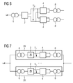
- FIG 5
- eine Variante der Ausführungsform nach
FIG 4 dargestellt ist und die - FIG 6 und 7
- zeigen jeweils eine weitere Ausführungsform des statischen Umformers nach der Erfindung.
- FIG. 1
- shows a first embodiment of the static converter according to the invention, in the
- FIGS. 2 and 3
- are variants of the feed circuit of the embodiment of the static converter
FIG. 1 represented, the - FIG. 4
- shows an advantageous embodiment of the static converter according to the invention, whereas in the
- FIG. 5
- a variant of the embodiment according to
FIG. 4 is shown and the - FIGS. 6 and 7
- each show a further embodiment of the static converter according to the invention.
In der
Der einphasenseitige Stromrichter 4 besteht aus zwei Phasenmodulen 12, die gleichspannungsseitig elektrisch parallel geschaltet sind und elektrisch mit der positiven und negativen Gleichspannungs-Sammelschiene P0 und N0 verknüpft sind. Jedes Phasenmodul 12 weist einen oberen und einen unteren Stromrichterzweig T1 bzw. T3 und T2 bzw. T4 auf. Jeweils ein Verknüpfungspunkt zweier elektrisch in Reihe geschalteter Stromrichterzweige T1,T2 bzw. T3,T4 eines jeden Phasenmoduls 12 bilden einen wechselspannungsseitigen Anschluss L1 und L2 für den einphasenseitigen Transformator 8. Dieser einphasenseitige Transformator 8 ist mit einem Einphasennetz verbunden. Bei diesem Einphasennetz handelt es sich beispielsweise um ein Bahnnetz. Dargestellt ist dieses Bahnnetz durch eine Fahrleitung 16. Alternativer kann der einphasenseitige Stromrichter 4 wechselspannungsseitig auch mittels einer Drossel 17 direkt an das Bahnnetz (Fahrleitung 16) angeschlossen werden.The single-
Jeder Stromrichterzweig T1,...,T4 dieses einphasenseitigen Stromrichters 4 weist wenigstens ein zweipoliges Subsystem 14 auf. In der dargestellten Ausführungsform sind von n zweipoligen Subsystemen 14 eines Stromrichterzweige T1,...,T4 jeweils drei dargestellt. Ein derartiges zweipoliges Subsystem 14 weist einen Modulkondensator CC und zwei abschaltbare Halbleiterschalter SF und SR auf. Diese beiden abschaltbaren Halbleiterschalter SF und SR sind elektrisch in Reihe geschaltet, wobei diese Reihenschaltung elektrisch parallel zum Modulkondensator CC geschaltet ist. Ein Verbindungspunkt der elektrisch in Reihe geschalteten abschaltbaren Halbleiterschalter SF SR bildet eine Anschlussklemme P, wogegen ein Verbindungspunkt von Modulkondensator CC und dem abschaltbaren Halbleiterschalter SF eine Anschlussklemme N bildet. Diese Ausführungsform des zweipoligen Subsystems 14 und dessen Funktionsweise ist in der eingangs genannten Veröffentlichung "ETG-Tagung 2002" näher beschrieben. Weitere Ausführungsformen des zweipoligen Subsystems 14 können der
Wie bei den bekannten statischen Umformern kann zur Begrenzung von Überspannungen im Zwischenkreis ein Bremssteller 18 vorgesehen werden. Dieser Bremssteller 18 weist einen Bremswiderstand 20 und wenigstens ein zweipoliges Subsystem 14 auf, die zwischen der positiven und negativen Gleichspannungs-Sammelschiene elektrisch in Reihe geschaltet sind. Ein derartiger modularer Bremssteller 18 ist in der
Auffällig bei diesen statischen Umformern nach der Erfindung ist, dass kein Zwischenkreiskondensator und keine Saugkreise mehr vorhanden sind, so dass bei diesem statischen Umformer außerhalb der Submodule 14 nicht mehr auf niederinduktiven Aufbau geachtet werden muss. Außerdem tritt dadurch kein niederohmiger Zwischenkreis-Kurzschluss mehr auf.It is noticeable in these static converters according to the invention that no intermediate circuit capacitor and no absorption circuits are no longer present, so that in this static converter outside the
In der
In der
In der
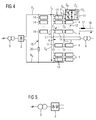
Die
In der
In der
Wird einer der beiden Umformerblöcke 26 als Netzkupplung gemäß der Veröffentlichung "ETG-Tagung 2002" ausgebildet, so kann dieser Umformerblock die Blindleistung des anderen Umformerblocks 26 bereitstellen. Außerdem können die Oberschwingungsströme, verursacht von der Einspeiseschaltung des ersten Umformerblock 26, durch den zweiten Umformerblock, dessen drehstromseitiger Stromrichter 2 selbstgeführt ausgebildet ist, kompensiert werden. Ferner kann Energie aus einem Bahnnetz über den Umformerblock mit einem drehstromseitigen selbstgeführten - und damit rückspeisefähigen - Stromrichter in ein Landesnetz erfolgen. Durch die Verwendung eines Umformerblocks mit einem drehstromseitigen selbstgeführten Stromrichter kann Blindleistung zwischen diesem Umformerblock und einem Landesnetz ausgetauscht werden, wodurch die Netzspannung dieses Landesnetzes gestützt wird, so dass der Umrichterblock 26 mit einem netzgeführten dreiphasigen Stromrichter ausgeführten drehstromseitigen Stromrichter 2 mit einer konstanten Netzspannung versorgt wird.If one of the two transformer blocks 26 is designed as a network coupling according to the publication "ETG Conference 2002", this converter block can provide the reactive power of the
Grundlage dieses erfindungsgemäßen statischen Umformers ist die Kombination eines oder mehrerer netzgeführter Stromrichter mit einem modularen Mehrpunktstromrichter mit zweipoligen Subsystemen. Daraus ergibt sich ein statischer Umformer, der gegenüber bekannten statischen Umformern einen wesentlich geringeren Aufwand aufweist, der im Zwischenkreis keine Energiespeicher (Zwischenkreiskondensator, Saugkreiskondensator, Saugkreisdrossel) aufweist, der wesentlich kostengünstiger ist, der einen geringeren Platz beansprucht, der einen geringeren Geräuschpegel aufweist, der nicht niederinduktiv aufgebaut sein muss und der eine geringere Verlustleistung aufweist.The basis of this static converter according to the invention is the combination of one or more line-commutated converters with a modular multi-point converter with two-pole subsystems. This results in a static converter, which compared to known static converters has a much lower cost, the intermediate circuit no energy storage (DC link capacitor, Saugkreiskondensator, Saugkreisdrossel), which is much cheaper, which takes up less space, the lower Noise level, which must not be constructed low inductance and has a lower power loss.
Claims (13)
Applications Claiming Priority (1)
| Application Number | Priority Date | Filing Date | Title |
|---|---|---|---|
| DE102008007658A DE102008007658A1 (en) | 2008-02-06 | 2008-02-06 | Static converter |
Publications (2)
| Publication Number | Publication Date |
|---|---|
| EP2088668A2 true EP2088668A2 (en) | 2009-08-12 |
| EP2088668A3 EP2088668A3 (en) | 2016-11-09 |
Family
ID=40637908
Family Applications (1)
| Application Number | Title | Priority Date | Filing Date |
|---|---|---|---|
| EP08171303.4A Withdrawn EP2088668A3 (en) | 2008-02-06 | 2008-12-11 | Static convertor |
Country Status (3)
| Country | Link |
|---|---|
| US (1) | US8054657B2 (en) |
| EP (1) | EP2088668A3 (en) |
| DE (1) | DE102008007658A1 (en) |
Cited By (5)
| Publication number | Priority date | Publication date | Assignee | Title |
|---|---|---|---|---|
| WO2011154196A3 (en) * | 2010-06-08 | 2012-10-11 | Siemens Aktiengesellschaft | Shaft-driven generator system |
| WO2014086428A1 (en) * | 2012-12-07 | 2014-06-12 | Siemens Aktiengesellschaft | Multistage converter with additional module |
| RU2600572C2 (en) * | 2014-07-23 | 2016-10-27 | Федеральное государственное унитарное предприятие Экспериментальный завод научного приборостроения со Специальным конструкторским бюро Российской академии наук | Method of controlling voltage and power |
| DE102018206448A1 (en) * | 2018-04-26 | 2019-10-31 | Siemens Aktiengesellschaft | Plant and method for energy supply, in particular for sheet energy supply |
| RU2766184C1 (en) * | 2021-08-25 | 2022-02-09 | Общество с ограниченной ответственностью "Научно-производственное объединение "Горизонт" | Static voltage converter |
Families Citing this family (10)
| Publication number | Priority date | Publication date | Assignee | Title |
|---|---|---|---|---|
| BRPI0822822B8 (en) * | 2008-06-17 | 2023-04-25 | Siemens Ag | METHOD FOR CLOSED-CIRCUIT CONTROL OF AT LEAST TWO CONVERTERS |
| DE102010043176A1 (en) * | 2010-10-29 | 2012-05-03 | Converteam Gmbh | Electrical circuit for converting electrical energy between a three-phase power grid and a single-phase power grid |
| CN102130619B (en) * | 2011-03-21 | 2014-07-02 | 中国电力科学研究院 | Voltage balancing control method for multi-level modular converter |
| US9899917B2 (en) * | 2011-04-01 | 2018-02-20 | Siemens Aktiengesellschaft | Method for producing an output voltage and assembly for performing the method |
| CN102403916B (en) * | 2011-11-04 | 2014-10-22 | 华北电力大学 | Design method of simulation accelerating circuit |
| DE102011087151A1 (en) | 2011-11-25 | 2013-05-29 | Ge Energy Power Conversion Gmbh | Multipoint power converter with brake chopper |
| CN104904106B (en) * | 2012-11-15 | 2018-01-02 | Abb 技术有限公司 | Apparatus and method for filtering the harmonic wave in railway contact line |
| DE102013203706B3 (en) * | 2013-03-05 | 2014-06-05 | Siemens Aktiengesellschaft | Method of operating modular high frequency converter mounted in e.g. electric vehicle, involves replacing switching position model parameters that represent influence of switch positions of input-side half-bridge by related duty cycle |
| CN107696873B (en) * | 2017-10-23 | 2023-12-22 | 西南交通大学 | Motor train unit traction transmission power supply system |
| RU190399U1 (en) * | 2018-12-17 | 2019-07-01 | Федеральное государственное унитарное предприятие Экспериментальный завод научного приборостроения со Специальным конструкторским бюро Российской академии наук | TRANSISTOR CONVERTER FOR GRAPHITE HEATERS |
Citations (2)
| Publication number | Priority date | Publication date | Assignee | Title |
|---|---|---|---|---|
| WO2007023061A2 (en) | 2005-08-26 | 2007-03-01 | Siemens Aktiengesellschaft | Pulse resistor (brake resistor) for a frequency converter in the higher voltage and capacity range |
| DE102005045090A1 (en) | 2005-09-21 | 2007-04-05 | Siemens Ag | Method for controlling a multiphase power converter with distributed energy storage |
Family Cites Families (11)
| Publication number | Priority date | Publication date | Assignee | Title |
|---|---|---|---|---|
| US4204265A (en) * | 1978-08-14 | 1980-05-20 | Mcleod James A | Static converter suitable for high input voltage applications |
| JPS5863082A (en) * | 1981-10-09 | 1983-04-14 | Fanuc Ltd | Inverter circuit |
| SE431601B (en) * | 1982-06-23 | 1984-02-13 | Asea Ab | DRIVE DEVICE WITH FORCED COMMUTION |
| ATE77019T1 (en) * | 1986-08-01 | 1992-06-15 | Bbc Brown Boveri & Cie | POWER CONVERTER CIRCUIT AND METHOD FOR CONTROLLING IT. |
| DE10103031B4 (en) * | 2001-01-24 | 2011-12-01 | Siemens Ag | Converter circuit with distributed energy storage and method for controlling such a converter circuit |
| FI115806B (en) * | 2003-07-04 | 2005-07-15 | Abb Oy | Frequency converter and electric motor drive |
| DE102005025422A1 (en) * | 2005-06-02 | 2006-12-21 | Siemens Ag | Three-phase inverter, has partial power converters placed in electrically conductive connection with windings and with DC-sided connectors and electrically connected in series, where each converter is frequency pulsed power converter |
| DE102005040543A1 (en) | 2005-08-26 | 2007-03-01 | Siemens Ag | Converter circuit with distributed energy storage |
| US7969755B2 (en) * | 2005-09-09 | 2011-06-28 | Siemens Aktiengesellschaft | Apparatus for electrical power transmission |
| WO2007028350A1 (en) | 2005-09-09 | 2007-03-15 | Siemens Akitengesellschaft | Device for electron energy transfer |
| DE102008007659A1 (en) * | 2008-02-06 | 2009-02-19 | Siemens Aktiengesellschaft | Indirect voltage converter, has upper and lower valve branches of each phase module of load-sided multi-phase power inverter with two-pole subsystem, and multi-phase network-guided power inverter provided as network-sided power inverter |
-
2008
- 2008-02-06 DE DE102008007658A patent/DE102008007658A1/en not_active Withdrawn
- 2008-12-11 EP EP08171303.4A patent/EP2088668A3/en not_active Withdrawn
-
2009
- 2009-02-04 US US12/320,759 patent/US8054657B2/en not_active Expired - Fee Related
Patent Citations (2)
| Publication number | Priority date | Publication date | Assignee | Title |
|---|---|---|---|---|
| WO2007023061A2 (en) | 2005-08-26 | 2007-03-01 | Siemens Aktiengesellschaft | Pulse resistor (brake resistor) for a frequency converter in the higher voltage and capacity range |
| DE102005045090A1 (en) | 2005-09-21 | 2007-04-05 | Siemens Ag | Method for controlling a multiphase power converter with distributed energy storage |
Non-Patent Citations (3)
| Title |
|---|
| "Konzepte zur Bereitstellung von 16 2/3Hz-Energie mittels Leistungselektronik", EB - ELEKTRISCHE BAHNEN, vol. 89, no. 11, 1991, pages 395 - 397 |
| "Modulares Stromrichterkonzept für Netzkupplungsanwendung bei hohen Spannungen", TAGUNGSBAND DER ETG-TAGUNG, 2002 |
| "Statischer Umformer zur Kupplung von Bahnnetzen und Landesnetzen", EB - ELEKTRISCHE BAHNEN, vol. 89, no. 11, 1991, pages 398 - 400 |
Cited By (6)
| Publication number | Priority date | Publication date | Assignee | Title |
|---|---|---|---|---|
| WO2011154196A3 (en) * | 2010-06-08 | 2012-10-11 | Siemens Aktiengesellschaft | Shaft-driven generator system |
| US9088229B2 (en) | 2010-06-08 | 2015-07-21 | Siemens Aktiengesellschaft | Shaft-driven generator system |
| WO2014086428A1 (en) * | 2012-12-07 | 2014-06-12 | Siemens Aktiengesellschaft | Multistage converter with additional module |
| RU2600572C2 (en) * | 2014-07-23 | 2016-10-27 | Федеральное государственное унитарное предприятие Экспериментальный завод научного приборостроения со Специальным конструкторским бюро Российской академии наук | Method of controlling voltage and power |
| DE102018206448A1 (en) * | 2018-04-26 | 2019-10-31 | Siemens Aktiengesellschaft | Plant and method for energy supply, in particular for sheet energy supply |
| RU2766184C1 (en) * | 2021-08-25 | 2022-02-09 | Общество с ограниченной ответственностью "Научно-производственное объединение "Горизонт" | Static voltage converter |
Also Published As
| Publication number | Publication date |
|---|---|
| DE102008007658A1 (en) | 2009-08-13 |
| EP2088668A3 (en) | 2016-11-09 |
| US20090196078A1 (en) | 2009-08-06 |
| US8054657B2 (en) | 2011-11-08 |
Similar Documents
| Publication | Publication Date | Title |
|---|---|---|
| EP2088668A2 (en) | Static convertor | |
| EP2241001B1 (en) | Converter | |
| EP2274825B1 (en) | Power supply device | |
| EP1311058B1 (en) | Frequency power converter | |
| EP2283233B1 (en) | Wind power plant and wind farm comprising plurality of wind power plants | |
| EP2681834B1 (en) | Modular converter cabinet system | |
| EP2282399B1 (en) | Static converter and method for starting the converter | |
| EP2898595B1 (en) | Modulat multilevel dc/dc converter for hvdc applications | |
| DE102010008978B4 (en) | Circuit arrangement for modular drive converter | |
| EP1710115B1 (en) | Circuit arrangement and driving method for an electric or hybrid vehicle with two dc power supplies | |
| EP3211784B1 (en) | Double submodule for a modular multilevel converter and modular multilevel converter comprising same | |
| WO2003090331A2 (en) | Power supply with a direct converter | |
| EP1186091B1 (en) | Indirect voltage converter | |
| EP2845288B1 (en) | On- or off-coupling of power in a branch at a node of a dc network by a voltage source connected in series | |
| EP2845303B1 (en) | Power converter and operating method for converting voltages | |
| EP0852841B1 (en) | Mains-adapted voltage-applying high-output oblique transformer controlled by a current converter | |
| DE3826524C2 (en) | Power feed circuit with suction throttle | |
| DE102005025422A1 (en) | Three-phase inverter, has partial power converters placed in electrically conductive connection with windings and with DC-sided connectors and electrically connected in series, where each converter is frequency pulsed power converter | |
| DE102015105889A1 (en) | Switching module and converter with at least one switching module | |
| DE10214509A1 (en) | Current converter arrangement supplying 3-phase load from single-phase network has reactive current converter with storage capacitor, power semiconductor switches, input choke parallel to capacitor | |
| DE19742429C1 (en) | Circuit arrangement e.g. for supplying electrical traction motor in multi-stage vehicle traction devices | |
| DE102013220864B3 (en) | power converters | |
| DE3831126C2 (en) | Inverter with impressed DC link voltage | |
| DE102013207894A1 (en) | Electrical circuit for converting direct current (DC) voltage into alternating current (AC) voltage or vice versa, has power converters that are connected on DC voltage side to form series arrangement and provided with modular switch | |
| AT408497B (en) | Apparatus for series/parallel conversion of converter-fed winding element systems of a three-phase machine, and connection of the converter outputs to a voltage stabilizing store |
Legal Events
| Date | Code | Title | Description |
|---|---|---|---|
| PUAI | Public reference made under article 153(3) epc to a published international application that has entered the european phase |
Free format text: ORIGINAL CODE: 0009012 |
|
| AK | Designated contracting states |
Kind code of ref document: A2 Designated state(s): AT BE BG CH CY CZ DE DK EE ES FI FR GB GR HR HU IE IS IT LI LT LU LV MC MT NL NO PL PT RO SE SI SK TR |
|
| AX | Request for extension of the european patent |
Extension state: AL BA MK RS |
|
| RAP1 | Party data changed (applicant data changed or rights of an application transferred) |
Owner name: SIEMENS AKTIENGESELLSCHAFT |
|
| PUAL | Search report despatched |
Free format text: ORIGINAL CODE: 0009013 |
|
| AK | Designated contracting states |
Kind code of ref document: A3 Designated state(s): AT BE BG CH CY CZ DE DK EE ES FI FR GB GR HR HU IE IS IT LI LT LU LV MC MT NL NO PL PT RO SE SI SK TR |
|
| AX | Request for extension of the european patent |
Extension state: AL BA MK RS |
|
| RIC1 | Information provided on ipc code assigned before grant |
Ipc: H02M 7/483 20070101ALI20161006BHEP Ipc: H02M 1/36 20070101ALI20161006BHEP Ipc: H02M 5/27 20060101AFI20161006BHEP Ipc: H02M 5/458 20060101ALI20161006BHEP Ipc: H02J 3/34 20060101ALI20161006BHEP |
|
| 17P | Request for examination filed |
Effective date: 20170505 |
|
| RBV | Designated contracting states (corrected) |
Designated state(s): AT BE BG CH CY CZ DE DK EE ES FI FR GB GR HR HU IE IS IT LI LT LU LV MC MT NL NO PL PT RO SE SI SK TR |
|
| AKX | Designation fees paid |
Designated state(s): AT BE BG CH CY CZ DE DK EE ES FI FR GB GR HR HU IE IS IT LI LT LU LV MC MT NL NO PL PT RO SE SI SK TR |
|
| AXX | Extension fees paid |
Extension state: AL Extension state: RS Extension state: BA Extension state: MK |
|
| RAP1 | Party data changed (applicant data changed or rights of an application transferred) |
Owner name: SIEMENS AKTIENGESELLSCHAFT |
|
| RAP1 | Party data changed (applicant data changed or rights of an application transferred) |
Owner name: SIEMENS MOBILITY GMBH |
|
| STAA | Information on the status of an ep patent application or granted ep patent |
Free format text: STATUS: THE APPLICATION IS DEEMED TO BE WITHDRAWN |
|
| 18D | Application deemed to be withdrawn |
Effective date: 20190702 |