EP2088057A1 - Wedge Arm Positive Rake Lock - Google Patents
Wedge Arm Positive Rake Lock Download PDFInfo
- Publication number
- EP2088057A1 EP2088057A1 EP09151572A EP09151572A EP2088057A1 EP 2088057 A1 EP2088057 A1 EP 2088057A1 EP 09151572 A EP09151572 A EP 09151572A EP 09151572 A EP09151572 A EP 09151572A EP 2088057 A1 EP2088057 A1 EP 2088057A1
- Authority
- EP
- European Patent Office
- Prior art keywords
- mounting bracket
- column jacket
- wedge arm
- assembly
- radial distance
- Prior art date
- Legal status (The legal status is an assumption and is not a legal conclusion. Google has not performed a legal analysis and makes no representation as to the accuracy of the status listed.)
- Withdrawn
Links
- 230000004044 response Effects 0.000 claims abstract description 9
- 230000007246 mechanism Effects 0.000 claims description 23
- 230000006835 compression Effects 0.000 claims description 22
- 238000007906 compression Methods 0.000 claims description 22
- 230000008878 coupling Effects 0.000 claims description 2
- 238000010168 coupling process Methods 0.000 claims description 2
- 238000005859 coupling reaction Methods 0.000 claims description 2
- 230000000712 assembly Effects 0.000 description 3
- 238000000429 assembly Methods 0.000 description 3
- 230000008859 change Effects 0.000 description 1
- 230000003116 impacting effect Effects 0.000 description 1
- 230000004048 modification Effects 0.000 description 1
- 238000012986 modification Methods 0.000 description 1
Images


Classifications
-
- B—PERFORMING OPERATIONS; TRANSPORTING
- B62—LAND VEHICLES FOR TRAVELLING OTHERWISE THAN ON RAILS
- B62D—MOTOR VEHICLES; TRAILERS
- B62D1/00—Steering controls, i.e. means for initiating a change of direction of the vehicle
- B62D1/02—Steering controls, i.e. means for initiating a change of direction of the vehicle vehicle-mounted
- B62D1/16—Steering columns
- B62D1/18—Steering columns yieldable or adjustable, e.g. tiltable
- B62D1/184—Mechanisms for locking columns at selected positions
-
- B—PERFORMING OPERATIONS; TRANSPORTING
- B62—LAND VEHICLES FOR TRAVELLING OTHERWISE THAN ON RAILS
- B62D—MOTOR VEHICLES; TRAILERS
- B62D1/00—Steering controls, i.e. means for initiating a change of direction of the vehicle
- B62D1/02—Steering controls, i.e. means for initiating a change of direction of the vehicle vehicle-mounted
- B62D1/16—Steering columns
- B62D1/18—Steering columns yieldable or adjustable, e.g. tiltable
- B62D1/187—Steering columns yieldable or adjustable, e.g. tiltable with tilt adjustment; with tilt and axial adjustment
-
- B—PERFORMING OPERATIONS; TRANSPORTING
- B62—LAND VEHICLES FOR TRAVELLING OTHERWISE THAN ON RAILS
- B62D—MOTOR VEHICLES; TRAILERS
- B62D1/00—Steering controls, i.e. means for initiating a change of direction of the vehicle
- B62D1/02—Steering controls, i.e. means for initiating a change of direction of the vehicle vehicle-mounted
- B62D1/16—Steering columns
- B62D1/18—Steering columns yieldable or adjustable, e.g. tiltable
- B62D1/19—Steering columns yieldable or adjustable, e.g. tiltable incorporating energy-absorbing arrangements, e.g. by being yieldable or collapsible
- B62D1/195—Yieldable supports for the steering column
Definitions
- the subject invention generally relates to s steering column assembly for a vehicle, and more specifically to an adjustable steering column assembly pivotably moveable about a pivot axis.
- Adjustable steering column assemblies often adjust in one or both of a telescoping direction along a longitudinal axis and in a tilt direction about a tilt (rake) axis.
- a tilt (rake) axis In order to meet crashworthiness requirements under some circumstances, it is necessary to prevent the steering column assembly from moving upward or pivoting into the instrument panel of a vehicle in response to an impact event, i.e., a crash event. In other words, it is necessary to prevent movement of the steering column assembly in the tilt direction in the event of the impact event.
- the steering column assemblies incorporate complex and expensive locking devices to lock the steering column assemblies in place and prevent undesirable movement of the steering column assembly in the tilt direction.
- These locking devices often incorporate small, intricate components that include interlocking teeth to mechanically lock the position of the steering column assembly.
- the interlocking teeth present problems associated with peak-to-peak tooth contact during adjustment. Additionally, the small intricate components complicate assembly of the steering column assembly.
- the subject invention provides a steering column assembly for a vehicle.
- the steering column assembly comprises a mounting bracket.
- the mounting bracket is configured for attachment to the vehicle.
- a column jacket extends along a longitudinal axis.
- the column jacket is pivotably coupled to the mounting bracket for pivotable movement relative to the mounting bracket about a pivot axis.
- a locking mechanism interconnects the mounting bracket and the column jacket.
- the locking mechanism is moveable between a release position and a lock position.
- the release position permitts the pivotable movement of the column jacket relative to the mounting bracket.
- the lock position secures the position of the column jacket relative to the mounting bracket during normal operation.
- a wedge arm is pivotably coupled to one of the mounting bracket and the column jacket.
- the wedge are is in wedging engagement against the other of the mounting bracket and the column jacket when the locking mechanism is in the lock position, thereby preventing the pivotable movement of the column jacket in response to an impact event.
- the wedge arm is released from the wedging engagement when the locking mechanism is in the release position to permit the pivotable movement.
- the subject invention provides the wedge arm to prevent the pivotable movement of the column jacket relative to the mounting bracket in response to the impact event.
- the wedge lock wedges between the moveable column jacket and the stationary mounting bracket. Accordingly, in response to the impact event, the column jacket is prohibited from movement relative to the mounting bracket because the wedge arm is wedged therebetween. Therefore, the steering column assembly need not incorporate the expensive and intricate interlocking toothed mechanisms to prevent the pivotal movement previously utilized in the prior art.
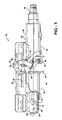
- Figure 1 is side plan view of a steering column assembly
- Figure 2 is a top plan view of the steering column assembly
- FIG. 3 is an enlarged fragmentary perspective view of the steering column assembly showing a wedge arm
- Figure 4 is an enlarged fragmentary side plan view of the steering column assembly showing the wedge arm locking the steering column assembly in a rake up position;
- Figure 5 is an enlarged fragmentary side plan view of the steering column assembly showing the wedge arm locking the steering column assembly in a rake down position;
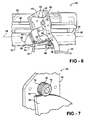
- Figure 6 is an enlarged fragmentary side plan view of the steering column assembly showing the wedge arm disengaged from wedging engagement
- Figure 7 is an enlarged fragmentary perspective view of the steering column assembly detailing serrations on the wedge arm and on a head portion of a shaft.
- a steering column assembly is shown generally at 20 .
- the steering column assembly 20 is for a vehicle, and is pivotable adjustable about a pivot axis 22 .
- the steering column assembly 20 may also be longitudinally adjustable in a telescope direction along a longitudinal axis 24 .
- the scope of the subject invention does not require that the steering column assembly 20 be longitudinally adjustable, i.e., telescopically adjustable.
- the steering column assembly 20 includes a column jacket 26 extending along the longitudinal axis 24 .
- the column jacket 26 rotatably supports a steering shaft 28 therein.
- a steering wheel (not shown) is mounted to an upper end of the steering shaft 28 as is well known.
- the column jacket 26 includes an upper jacket 30 and a lower jacket 32 .
- the column jacket 26 may be configured in a manner different than shown or described herein and still fall within the scope of the claims.
- the column jacket 26 is coupled to a mounting bracket 34.
- the mounting bracket 34 is configured for attachment to the vehicle. Accordingly, the mounting bracket 34 mounts the steering column assembly 20 to the vehicle.
- the mounting bracket 34 defines a pair of flanges 36 extending downwardly, transverse to the longitudinal axis 24 along opposite sides of the column jacket 26 .
- Each of the pair of flanges 36 defines a first telescope slot 38 extending along the longitudinal axis 24 to permit the longitudinal adjustment of the column jacket 26 relative to the mounting bracket 34 .
- the mounting bracket 34 may be configured differently than shown or described herein and still fall within the scope of the claims.
- a fastener 40 extends through each of the first telescope slots 38 into engagement with the column jacket 26 to pivotably couple the column jacket 26 to the mounting bracket 34.
- Each of the fasteners 40 is aligned along and defines the pivot axis 22 about which the column jacket 26 pivots. Accordingly, the column jacket 26 is pivotably moveable relative to the mounting bracket 34 about the pivot axis 22 .
- the fasteners 40 are moveable within the first telescope slots 38 during movement of the column jacket 26 in the telescope direction, i.e., the fasteners 40 move with the column jacket 26 as the column jacket 26 moves in the telescope direction.
- the length of the first telescope slots 38 delimits the limits of the telescopic movement. It should be appreciated that the column jacket 26 may be coupled to the mounting bracket 34 and the pivot axis 22 defined in a manner different than shown or described herein and still fall within the scope of the claims.
- a compression bracket 42 is fixedly mounted to the column jacket 26 and interconnects the column jacket 26 and the mounting bracket 34.
- the compression bracket 42 includes a pair of sidewalls 44 extending upwardly along opposing sides of the column jacket 26 transverse to the longitudinal axis 24 .
- Each of the pair of sidewalls 44 defines a rake slot 46 extending transverse, i.e., generally perpendicular to the longitudinal axis 24 , to permit the pivotal movement or adjustment about the pivot axis 22 of the column jacket 26 relative to the mounting bracket 34 .
- the compression bracket 42 may be configured differently than shown or described herein and still fall within the scope of the claims.
- the mounting bracket 34 further defines pair of second telescope slots 48 extending along the longitudinal axis 24 and disposed adjacent the rake slots 46 of the compression bracket 42.
- a shaft 50 commonly referred to as a rake bolt, extends through the compression bracket 42 and the mounting bracket 34 transverse to the longitudinal axis 24 .
- the shaft 50 may be rotatable for moving a locking mechanism 52 described below, between a lock position and a release position. However, it should be appreciated that the shaft 50 need not be rotatable to fall within the scope of the claims.
- the shaft 50 extends through the pair of second telescope slots 48 and the rake slots 46 .
- the shaft 50 moves within the rake slots 46 as the compression bracket 42 pivots about the pivot axis 22 , i.e., as the column jacket 26 and the compression bracket 42 move during adjustment of the column bracket in the tilt direction , the position of the shaft 50 within the rake slots 46 changes. Accordingly, during the pivotal movement of the column jacket 26 , the shaft 50 remains positionally fixed relative to the mounting bracket 34 . However, it should be appreciated that the shaft 50 may move with the column jacket 26 during telescopic adjustment of the column jacket 26 .
- the locking mechanism 52 interconnects the mounting bracket 34 and the column jacket 26 .
- the locking mechanism 52 is moveable between the release position and the lock position.
- the release position permits the pivotable movement of the column jacket 26 relative to the mounting bracket 34 .
- the lock position secures the position of the column jacket 26 relative to the mounting bracket 34 during normal operation. More specifically, the locking mechanism 52 compresses the compression bracket 42 against the mounting bracket 34 when in the lock position and releases the compression bracket 42 from the mounting bracket 34 when in the release position. Accordingly, the locking mechanism 52 retains the desired position of the column jacket 26, and thereby the steering wheel, relative to the mounting bracket 34.
- the locking mechanism 52 may not provide a sufficient clamping force to resist a sudden and severe upward force applied to the steering column assembly 20 by an operator of the vehicle impacting the steering wheel.
- a handle 54 is pivotably coupled to one of the mounting bracket 34 and the column jacket 26 .
- the handle may be coupled to the locking mechanism 52 to move the locking mechanism 52 between the release position and the lock position. If the shaft 50 is rotatable, then the handle 54 may be mounted to the shaft 50 for rotating the shaft 50 .
- the locking mechanism 52 may be coupled to the shaft 50 , with the locking mechanism 52 being actuated by rotation of the handle 54 about the shaft 50 as is well known. It should be appreciated that there are many types locking mechanisms 52 known in the art.
- the locking mechanism 52 includes a cam and a cam follower coupled to the shaft 50 to provide a clamping force.
- the locking mechanism 52 of the subject invention may include any suitable device capable of clamping the compression bracket 42 and the mounting bracket 34 together to secure the position of the column jacket 26 relative to the mounting bracket 34 as is well known.
- a wedge arm 56 is pivotably coupled to one of the mounting bracket 34 and the column jacket 26 .
- the wedge arm 56 is in wedging engagement against the other of the mounting bracket 34 and the column jacket 26 when the locking mechanism 52 is in the lock position.
- the wedging engagement prevents the pivotable movement of the column jacket 26 in a generally upward direction in response to the impact event.
- the wedge arm 56 is released from the wedging engagement when the locking mechanism 52 is in the release position to permit the pivotable movement.
- the wedge arm 56 includes an attachment point 58 pivotably coupling the wedge arm 56 to one of the mounting bracket 34 and the column jacket 26 .
- the attachment point 58 interconnects the wedge arm 56 to the compression bracket 42 .
- a pin 60 interconnects the wedge arm 56 and the compression bracket 42 at the attachment point 58 .
- the wedge arm 56 may be rotatably coupled to one of the mounting bracket 34 and the column jacket 26 in some other manner not shown or described herein.
- the wedge further includes a contact edge 62 .
- the contact edge 62 is spaced from the attachment point 58 a radial distance 64.
- the contact edge 62 wedges against the other of the mounting bracket 34 and the column jacket 26 .
- the wedge arm 56 is coupled to one of the column jacket 26 and the mounting bracket 34 and the contact edge 62 of the wedge arm 56 wedges against the other of the column jacket 26 and the mounting bracket 34 . As shown, the contact edge 62 wedges against the mounting bracket 34 .
- the radial distance 64 that the contact edge 62 is spaced from the attachment point 58 is variable along a length of the contact edge 62 .
- the variable radial distance 64 of the wedge arm 56 corresponds with different relative positions between the column jacket 26 and the mounting bracket 34 .
- the wedge arm 56 includes a first edge 66 and a second edge 68 .
- the first edge 66 defines a first radial distance 70.
- the second edge 68 is angularly spaced from the first edge 66 about the attachment point 58 and defines a second radial distance 72 .
- the second radial distance 72 is different from the first radial distance 70 .
- the radial distance 64 of the contact edge 62 from the attachment point 58 varies between the first radial distance 70 and the second radial distance 72 .
- the contact edge 62 defines a smooth arcuate shape extending between distal ends of the first edge 66 and the second edge 68 .
- the wedge arm 56 is mounted to the compression bracket 42 , the wedge arm 56 moves with the column jacket 26 and the compression bracket 42 during adjustment of the column jacket 26 in the tilt direction about the pivot axis 22 . Accordingly, because the shaft 50 does not move with column jacket 26 and the compression bracket 42 during the tilting movement, the distance between the attachment point 58 and the shaft 50 changes in response to adjustment of the column jacket 26 in the tilt direction. As such, in order to maintain engagement between the wedge arm 56 and the head portion 74 of the shaft 50 , the wedge arm 56 includes the variable radial distance 64 . The variable radial distance 64 of the wedge arm 56 allows for the wedging engagement within the full range of pivotal movement of the column jacket 26 relative to the mounting bracket 34 .
- a spring 76 is connected to the wedge arm 56 and to the handle 54.
- the spring 76 provides a biasing force to move the wedge arm 56 into engagement with the mounting bracket 34 upon rotation of the handle 54 into the lock position, i.e., the spring 76 pulls the wedge arm 56 into an abutting relationship with the mounting bracket 34 .
- the spring 76 releases the biasing force, and allows the wedge arm 56 to rotate about the pin 60 , away from the mounting bracket 34 to permit the pivotal movement of the column jacket 26 .
- the handle 54 is configured to engage the wedge arm 56 during rotation into the release position to push against the wedge arm 56 and cause the wedge arm 56 to rotate out of wedging engagement.
- the shaft 50 includes a head portion 74 .
- the head portion 74 extends outward past the handle 54 .
- the wedge arm 56 is rotatably mounted to the compression bracket 42 by the pin 60 and engages the mounting bracket 34 .
- the wedge arm 56 wedges against the shaft 50
- the wedge arm 56 wedges against the head portion 74 of the shaft 50 .
- the head portion 74 of the shaft 50 being coupled to the mounting bracket 34 and positionally fixed against generally vertical movement relative to the mounting bracket 34. It should be appreciated, however, that the wedge arm 56 may alternatively wedge against some other portion of the mounting bracket 34 other than the head portion 74 as shown.
- the contact edge 62 of the wedge arm 56 and/or the shaft 50 and the head portion 74 of the shaft 50 may include a smooth finish.
- the contact edge 62 of the wedge arm 56 and/or the shaft 50 and the head portion 74 of the shaft 50 may be machined to include serrations 78 or ridges to engage each other.
- the serrations 78 reduce a potential for slippage between the shaft 50 or the head portion 74 of the shaft 50 and the contact edge 62 of the wedge arm 56.
- the contact edge 62 may include serrations 78 for engaging the shaft 50
- the shaft 50 may include serrations 78 for engaging the wedge arm 56 .
- the column jacket 26 and thereby the compression bracket 42 are positioned in a desired position and the handle 54 is moved into the lock position to secure the position of the column jacket 26 .
- the spring 76 draws the contact edge 62 of the wedge arm 56 into abutting engagement with the head portion 74 of the shaft 50 , thereby wedging the wedge arm 56 between the pin 60 and the shaft 50 .
- the variable radial distance 64 of the wedge arm 56 accommodates all possible positions of the column jacket 26 within the range of the pivotal movement, i.e., as the position of the column jacket 26 is adjusted in the tilt direction, the relative position of the wedge arm 56 to the shaft 50 will change as well, so as to always be in contact with the head portion 74 of the shaft 50 .
- the wedge arm 56 prevents undesirable upwardly transverse movement of the column jacket 26 in the pivot direction because the shaft 50 is restricted against vertical movement relative to the column jacket 26 , i.e., the shaft 50 is prevented from moving in a direction upwardly transverse to the longitudinal axis 24 . This is because the wedge arm 56 is coupled to the compression bracket 42 and wedged against the head portion 74 of the shaft 50 .
- the wedge arm 56 may be rotatably coupled to the mounting bracket 34 and vertically restrained relative to the column jacket 26 , and the shaft 50 moveable with the column jacket 26 during the pivotal movement of the column jacket 26 .
- the attachment point 58 may interconnect the wedge arm 56 to the mounting bracket 34, with the wedge arm 56 wedging against the compression bracket 42 .
Landscapes
- Engineering & Computer Science (AREA)
- Chemical & Material Sciences (AREA)
- Combustion & Propulsion (AREA)
- Transportation (AREA)
- Mechanical Engineering (AREA)
- Steering Controls (AREA)
Abstract
A steering column assembly (20) includes a column jacket (26) coupled to a mounting bracket (34), with the column jacket (26) pivotably moveable about a pivot axis (22) relative to the mounting bracket (34). A wedge arm (56) is pivotably mounted to one of the column jacket (26) and the mounting bracket (34) and wedges against the other of the column jacket (26) and the mounting bracket (34). The wedge arm (56) prohibits the pivotable movement of the column jacket (26) relative to the mounting bracket (34) in response to an impact event. The wedge arm (56) includes an arcuate shape having a variable radial distance (64) between a pivot attachment point (58) and a contact edge (62). The variable radial distance (64) permits the wedge arm (56) to fit between components of the column jacket (26) and the mounting bracket (34) when the column jacket (26) is positioned in different positions relative to the mounting bracket (34).
Description
- The subject invention generally relates to s steering column assembly for a vehicle, and more specifically to an adjustable steering column assembly pivotably moveable about a pivot axis.
- Adjustable steering column assemblies often adjust in one or both of a telescoping direction along a longitudinal axis and in a tilt direction about a tilt (rake) axis. In order to meet crashworthiness requirements under some circumstances, it is necessary to prevent the steering column assembly from moving upward or pivoting into the instrument panel of a vehicle in response to an impact event, i.e., a crash event. In other words, it is necessary to prevent movement of the steering column assembly in the tilt direction in the event of the impact event.
- Currently, the steering column assemblies incorporate complex and expensive locking devices to lock the steering column assemblies in place and prevent undesirable movement of the steering column assembly in the tilt direction. These locking devices often incorporate small, intricate components that include interlocking teeth to mechanically lock the position of the steering column assembly. However, the interlocking teeth present problems associated with peak-to-peak tooth contact during adjustment. Additionally, the small intricate components complicate assembly of the steering column assembly.
- The subject invention provides a steering column assembly for a vehicle. The steering column assembly comprises a mounting bracket. The mounting bracket is configured for attachment to the vehicle. A column jacket extends along a longitudinal axis. The column jacket is pivotably coupled to the mounting bracket for pivotable movement relative to the mounting bracket about a pivot axis. A locking mechanism interconnects the mounting bracket and the column jacket. The locking mechanism is moveable between a release position and a lock position. The release position permitts the pivotable movement of the column jacket relative to the mounting bracket. The lock position secures the position of the column jacket relative to the mounting bracket during normal operation. A wedge arm is pivotably coupled to one of the mounting bracket and the column jacket. The wedge are is in wedging engagement against the other of the mounting bracket and the column jacket when the locking mechanism is in the lock position, thereby preventing the pivotable movement of the column jacket in response to an impact event. The wedge arm is released from the wedging engagement when the locking mechanism is in the release position to permit the pivotable movement.
- Accordingly, the subject invention provides the wedge arm to prevent the pivotable movement of the column jacket relative to the mounting bracket in response to the impact event. The wedge lock wedges between the moveable column jacket and the stationary mounting bracket. Accordingly, in response to the impact event, the column jacket is prohibited from movement relative to the mounting bracket because the wedge arm is wedged therebetween. Therefore, the steering column assembly need not incorporate the expensive and intricate interlocking toothed mechanisms to prevent the pivotal movement previously utilized in the prior art.
- Other advantages of the present invention will be readily appreciated, as the same becomes better understood by reference to the following detailed description when considered in connection with the accompanying drawings wherein:
-
Figure 1 is side plan view of a steering column assembly; -
Figure 2 is a top plan view of the steering column assembly; -
Figure 3 is an enlarged fragmentary perspective view of the steering column assembly showing a wedge arm; -
Figure 4 is an enlarged fragmentary side plan view of the steering column assembly showing the wedge arm locking the steering column assembly in a rake up position; -
Figure 5 is an enlarged fragmentary side plan view of the steering column assembly showing the wedge arm locking the steering column assembly in a rake down position; -
Figure 6 is an enlarged fragmentary side plan view of the steering column assembly showing the wedge arm disengaged from wedging engagement; and -
Figure 7 is an enlarged fragmentary perspective view of the steering column assembly detailing serrations on the wedge arm and on a head portion of a shaft. - Referring to the Figures, wherein like numerals indicate corresponding parts throughout the several views, a steering column assembly is shown generally at 20. Referring to
Figures 1 and2 , thesteering column assembly 20 is for a vehicle, and is pivotable adjustable about apivot axis 22. Thesteering column assembly 20 may also be longitudinally adjustable in a telescope direction along alongitudinal axis 24. However, the scope of the subject invention does not require that thesteering column assembly 20 be longitudinally adjustable, i.e., telescopically adjustable. - The
steering column assembly 20 includes acolumn jacket 26 extending along thelongitudinal axis 24. Thecolumn jacket 26 rotatably supports asteering shaft 28 therein. A steering wheel (not shown) is mounted to an upper end of thesteering shaft 28 as is well known. As shown, thecolumn jacket 26 includes anupper jacket 30 and alower jacket 32. However, it should be appreciated that thecolumn jacket 26 may be configured in a manner different than shown or described herein and still fall within the scope of the claims. - The
column jacket 26 is coupled to amounting bracket 34. Themounting bracket 34 is configured for attachment to the vehicle. Accordingly, themounting bracket 34 mounts thesteering column assembly 20 to the vehicle. As shown, themounting bracket 34 defines a pair offlanges 36 extending downwardly, transverse to thelongitudinal axis 24 along opposite sides of thecolumn jacket 26. Each of the pair offlanges 36 defines afirst telescope slot 38 extending along thelongitudinal axis 24 to permit the longitudinal adjustment of thecolumn jacket 26 relative to themounting bracket 34. It should be appreciated that themounting bracket 34 may be configured differently than shown or described herein and still fall within the scope of the claims. - A
fastener 40 extends through each of thefirst telescope slots 38 into engagement with thecolumn jacket 26 to pivotably couple thecolumn jacket 26 to themounting bracket 34. Each of thefasteners 40 is aligned along and defines thepivot axis 22 about which thecolumn jacket 26 pivots. Accordingly, thecolumn jacket 26 is pivotably moveable relative to themounting bracket 34 about thepivot axis 22. - The
fasteners 40 are moveable within thefirst telescope slots 38 during movement of thecolumn jacket 26 in the telescope direction, i.e., thefasteners 40 move with thecolumn jacket 26 as thecolumn jacket 26 moves in the telescope direction. The length of thefirst telescope slots 38 delimits the limits of the telescopic movement. It should be appreciated that thecolumn jacket 26 may be coupled to themounting bracket 34 and thepivot axis 22 defined in a manner different than shown or described herein and still fall within the scope of the claims. - A
compression bracket 42, commonly referred to as a rake bracket, is fixedly mounted to thecolumn jacket 26 and interconnects thecolumn jacket 26 and themounting bracket 34. Thecompression bracket 42 includes a pair ofsidewalls 44 extending upwardly along opposing sides of thecolumn jacket 26 transverse to thelongitudinal axis 24. Each of the pair ofsidewalls 44 defines arake slot 46 extending transverse, i.e., generally perpendicular to thelongitudinal axis 24, to permit the pivotal movement or adjustment about thepivot axis 22 of thecolumn jacket 26 relative to themounting bracket 34. It should be appreciated that thecompression bracket 42 may be configured differently than shown or described herein and still fall within the scope of the claims. - The
mounting bracket 34 further defines pair ofsecond telescope slots 48 extending along thelongitudinal axis 24 and disposed adjacent therake slots 46 of thecompression bracket 42. Ashaft 50, commonly referred to as a rake bolt, extends through thecompression bracket 42 and themounting bracket 34 transverse to thelongitudinal axis 24. Theshaft 50 may be rotatable for moving alocking mechanism 52 described below, between a lock position and a release position. However, it should be appreciated that theshaft 50 need not be rotatable to fall within the scope of the claims. Theshaft 50 extends through the pair ofsecond telescope slots 48 and therake slots 46. Theshaft 50 moves within therake slots 46 as thecompression bracket 42 pivots about thepivot axis 22, i.e., as thecolumn jacket 26 and thecompression bracket 42 move during adjustment of the column bracket in the tilt direction , the position of theshaft 50 within therake slots 46 changes. Accordingly, during the pivotal movement of thecolumn jacket 26, theshaft 50 remains positionally fixed relative to the mountingbracket 34. However, it should be appreciated that theshaft 50 may move with thecolumn jacket 26 during telescopic adjustment of thecolumn jacket 26. - The
locking mechanism 52 interconnects the mountingbracket 34 and thecolumn jacket 26. Thelocking mechanism 52 is moveable between the release position and the lock position. The release position permits the pivotable movement of thecolumn jacket 26 relative to the mountingbracket 34. The lock position secures the position of thecolumn jacket 26 relative to the mountingbracket 34 during normal operation. More specifically, thelocking mechanism 52 compresses thecompression bracket 42 against the mountingbracket 34 when in the lock position and releases thecompression bracket 42 from the mountingbracket 34 when in the release position. Accordingly, thelocking mechanism 52 retains the desired position of thecolumn jacket 26, and thereby the steering wheel, relative to the mountingbracket 34. However, it should be appreciated that during an impact event, such as a vehicle collision, thelocking mechanism 52 may not provide a sufficient clamping force to resist a sudden and severe upward force applied to thesteering column assembly 20 by an operator of the vehicle impacting the steering wheel. - A
handle 54 is pivotably coupled to one of the mountingbracket 34 and thecolumn jacket 26. The handle may be coupled to thelocking mechanism 52 to move thelocking mechanism 52 between the release position and the lock position. If theshaft 50 is rotatable, then thehandle 54 may be mounted to theshaft 50 for rotating theshaft 50. Thelocking mechanism 52 may be coupled to theshaft 50, with thelocking mechanism 52 being actuated by rotation of thehandle 54 about theshaft 50 as is well known. It should be appreciated that there are manytypes locking mechanisms 52 known in the art. Typically, thelocking mechanism 52 includes a cam and a cam follower coupled to theshaft 50 to provide a clamping force. As such, thelocking mechanism 52 of the subject invention may include any suitable device capable of clamping thecompression bracket 42 and the mountingbracket 34 together to secure the position of thecolumn jacket 26 relative to the mountingbracket 34 as is well known. - Referring to
Figures 3 through 6 , awedge arm 56 is pivotably coupled to one of the mountingbracket 34 and thecolumn jacket 26. As shown inFigures 3 through 5 , thewedge arm 56 is in wedging engagement against the other of the mountingbracket 34 and thecolumn jacket 26 when thelocking mechanism 52 is in the lock position. The wedging engagement prevents the pivotable movement of thecolumn jacket 26 in a generally upward direction in response to the impact event. As shown inFigure 6 , thewedge arm 56 is released from the wedging engagement when thelocking mechanism 52 is in the release position to permit the pivotable movement. - The
wedge arm 56 includes anattachment point 58 pivotably coupling thewedge arm 56 to one of the mountingbracket 34 and thecolumn jacket 26. As shown in the Figures, theattachment point 58 interconnects thewedge arm 56 to thecompression bracket 42. Specifically, apin 60 interconnects thewedge arm 56 and thecompression bracket 42 at theattachment point 58. However, it should be appreciated that thewedge arm 56 may be rotatably coupled to one of the mountingbracket 34 and thecolumn jacket 26 in some other manner not shown or described herein. - The wedge further includes a
contact edge 62. Thecontact edge 62 is spaced from the attachment point 58 aradial distance 64. Thecontact edge 62 wedges against the other of the mountingbracket 34 and thecolumn jacket 26. In other words, thewedge arm 56 is coupled to one of thecolumn jacket 26 and the mountingbracket 34 and thecontact edge 62 of thewedge arm 56 wedges against the other of thecolumn jacket 26 and the mountingbracket 34. As shown, thecontact edge 62 wedges against the mountingbracket 34. - The
radial distance 64 that thecontact edge 62 is spaced from theattachment point 58 is variable along a length of thecontact edge 62. Thevariable radial distance 64 of thewedge arm 56 corresponds with different relative positions between thecolumn jacket 26 and the mountingbracket 34. Accordingly, thewedge arm 56 includes afirst edge 66 and asecond edge 68. Thefirst edge 66 defines afirst radial distance 70. Thesecond edge 68 is angularly spaced from thefirst edge 66 about theattachment point 58 and defines asecond radial distance 72. Thesecond radial distance 72 is different from thefirst radial distance 70. Theradial distance 64 of thecontact edge 62 from theattachment point 58 varies between thefirst radial distance 70 and thesecond radial distance 72. As shown, thecontact edge 62 defines a smooth arcuate shape extending between distal ends of thefirst edge 66 and thesecond edge 68. - Because the
wedge arm 56 is mounted to thecompression bracket 42, thewedge arm 56 moves with thecolumn jacket 26 and thecompression bracket 42 during adjustment of thecolumn jacket 26 in the tilt direction about thepivot axis 22. Accordingly, because theshaft 50 does not move withcolumn jacket 26 and thecompression bracket 42 during the tilting movement, the distance between theattachment point 58 and theshaft 50 changes in response to adjustment of thecolumn jacket 26 in the tilt direction. As such, in order to maintain engagement between thewedge arm 56 and thehead portion 74 of theshaft 50, thewedge arm 56 includes thevariable radial distance 64. Thevariable radial distance 64 of thewedge arm 56 allows for the wedging engagement within the full range of pivotal movement of thecolumn jacket 26 relative to the mountingbracket 34. - A
spring 76 is connected to thewedge arm 56 and to thehandle 54. Thespring 76 provides a biasing force to move thewedge arm 56 into engagement with the mountingbracket 34 upon rotation of thehandle 54 into the lock position, i.e., thespring 76 pulls thewedge arm 56 into an abutting relationship with the mountingbracket 34. As thehandle 54 is positioned in the release position, thespring 76 releases the biasing force, and allows thewedge arm 56 to rotate about thepin 60, away from the mountingbracket 34 to permit the pivotal movement of thecolumn jacket 26. Thehandle 54 is configured to engage thewedge arm 56 during rotation into the release position to push against thewedge arm 56 and cause thewedge arm 56 to rotate out of wedging engagement. - As shown, the
shaft 50 includes ahead portion 74. Thehead portion 74 extends outward past thehandle 54. As described above, thewedge arm 56 is rotatably mounted to thecompression bracket 42 by thepin 60 and engages the mountingbracket 34. Specifically, thewedge arm 56 wedges against theshaft 50, and more specifically, thewedge arm 56 wedges against thehead portion 74 of theshaft 50. Thehead portion 74 of theshaft 50 being coupled to the mountingbracket 34 and positionally fixed against generally vertical movement relative to the mountingbracket 34. It should be appreciated, however, that thewedge arm 56 may alternatively wedge against some other portion of the mountingbracket 34 other than thehead portion 74 as shown. - The
contact edge 62 of thewedge arm 56 and/or theshaft 50 and thehead portion 74 of theshaft 50 may include a smooth finish. Alternatively, referring toFigure 7 , thecontact edge 62 of thewedge arm 56 and/or theshaft 50 and thehead portion 74 of theshaft 50 may be machined to includeserrations 78 or ridges to engage each other. Theserrations 78 reduce a potential for slippage between theshaft 50 or thehead portion 74 of theshaft 50 and thecontact edge 62 of thewedge arm 56. Accordingly, it should be appreciated that thecontact edge 62 may includeserrations 78 for engaging theshaft 50, and/or theshaft 50 may includeserrations 78 for engaging thewedge arm 56. - In operation, the
column jacket 26 and thereby thecompression bracket 42 are positioned in a desired position and thehandle 54 is moved into the lock position to secure the position of thecolumn jacket 26. As thehandle 54 is moved into the lock position, thespring 76 draws thecontact edge 62 of thewedge arm 56 into abutting engagement with thehead portion 74 of theshaft 50, thereby wedging thewedge arm 56 between thepin 60 and theshaft 50. Thevariable radial distance 64 of thewedge arm 56 accommodates all possible positions of thecolumn jacket 26 within the range of the pivotal movement, i.e., as the position of thecolumn jacket 26 is adjusted in the tilt direction, the relative position of thewedge arm 56 to theshaft 50 will change as well, so as to always be in contact with thehead portion 74 of theshaft 50. In response to a crash event, thewedge arm 56 prevents undesirable upwardly transverse movement of thecolumn jacket 26 in the pivot direction because theshaft 50 is restricted against vertical movement relative to thecolumn jacket 26, i.e., theshaft 50 is prevented from moving in a direction upwardly transverse to thelongitudinal axis 24. This is because thewedge arm 56 is coupled to thecompression bracket 42 and wedged against thehead portion 74 of theshaft 50. - While the
steering column assembly 20 has been described having theshaft 50 vertically restrained from movement, with thewedge arm 56 coupled to thecolumn jacket 26 for vertical movement therewith during the pivotal movement, it should be appreciated that the configuration may be reversed. As such, thewedge arm 56 may be rotatably coupled to the mountingbracket 34 and vertically restrained relative to thecolumn jacket 26, and theshaft 50 moveable with thecolumn jacket 26 during the pivotal movement of thecolumn jacket 26. In other words, theattachment point 58 may interconnect thewedge arm 56 to the mountingbracket 34, with thewedge arm 56 wedging against thecompression bracket 42. - The invention has been described in an illustrative manner, and it is to be understood that the terminology which has been used is intended to be in the nature of words of description rather than of limitation. As is now apparent to those skilled in the art, many modifications and variations of the present invention are possible in light of the above teachings. It is, therefore, to be understood that within the scope of the appended claims, wherein reference numerals are merely for convenience and are not to be in any way limiting, the invention may be practiced otherwise than as specifically described.
Claims (10)
- A steering column assembly (20) for a vehicle, said assembly (20) comprising:a mounting bracket (34) configured for attachment to the vehicle;a column jacket (26) extending along a longitudinal axis (24) and pivotably coupled to said mounting bracket (34) for pivotable movement relative to said mounting bracket (34) about a pivot axis (22);a locking mechanism (52) interconnecting said mounting bracket (34) and said column jacket (26) and moveable between a release position permitting said pivotable movement of said column jacket (26) relative to said mounting bracket (34) and a lock position securing the position of said column jacket (26) relative to said mounting bracket (34) during normal operation; anda wedge arm (56) pivotably coupled to one of said mounting bracket (34) and said column jacket (26) and in wedging engagement against the other of said mounting bracket (34) and said column jacket (26) when said locking mechanism (52) is in said lock position to prevent said pivotable movement of said column jacket (26) in a generally upward direction in response to an impact event and released from said wedging engagement when said locking mechanism (52) is in said release position to permit said pivotable movement.
- An assembly (20) as set forth in claim 1 wherein said wedge arm (56) includes an attachment point (58) pivotably coupling said wedge arm (56) to one of said mounting bracket (34) and said column jacket (26) and a contact edge (62) spaced from said attachment point (58) a radial distance (64) for wedging against the other of said mounting bracket (34) and said column jacket (26).
- An assembly (20) as set forth in claim 2 wherein said radial distance (64) is variable along said contact edge (62) to correspond with different relative positions between said column jacket (26) and said mounting bracket (34).
- An assembly (20) as set forth in any of claims 2 and 3 wherein said wedge arm (56) includes a first edge (66) defining a first radial distance (70) and a second edge (68) angularly spaced from said first edge (66) about said attachment point (58) and defining a second radial distance (72) different from said first radial distance (70) with said radial distance (64) of said contact edge (62) variable between said first radial distance (70) and said second radial distance (72).
- An assembly (20) as set forth in any of claims 2, 3 and 4 wherein said contact edge (62) defines an arcuate shape.
- An assembly (20) as set forth in any of claims 2, 3, 4 and 5 wherein said column jacket (26) includes a compression bracket (42) with said attachment point (58) interconnecting said wedge arm (56) to said compression bracket (42).
- An assembly (20) as set forth in claim 6 further comprising a shaft (50) extending through said compression bracket (42) and said mounting bracket (34) transverse to said longitudinal axis (24).
- An assembly (20) as set forth in any of claims 6 and 7 further comprising a handle (54) pivotably coupled to one of said mounting bracket (34) and said column jacket (26).
- An assembly (20) as set forth in claim 8 further comprising a spring (76) connected to said wedge arm (56) and said handle (54) for biasing said wedge arm (56) toward said handle (54).
- An assembly (20) as set forth in any of claims 7, 8 and 9 wherein said wedge arm (56) wedges against said shaft (50).
Applications Claiming Priority (2)
| Application Number | Priority Date | Filing Date | Title |
|---|---|---|---|
| US6503008P | 2008-02-08 | 2008-02-08 | |
| US12/133,937 US7798037B2 (en) | 2008-02-08 | 2008-06-05 | Wedge arm positive rake lock |
Publications (1)
| Publication Number | Publication Date |
|---|---|
| EP2088057A1 true EP2088057A1 (en) | 2009-08-12 |
Family
ID=40565077
Family Applications (1)
| Application Number | Title | Priority Date | Filing Date |
|---|---|---|---|
| EP09151572A Withdrawn EP2088057A1 (en) | 2008-02-08 | 2009-01-28 | Wedge Arm Positive Rake Lock |
Country Status (3)
| Country | Link |
|---|---|
| US (1) | US7798037B2 (en) |
| EP (1) | EP2088057A1 (en) |
| CN (1) | CN101503097B (en) |
Cited By (2)
| Publication number | Priority date | Publication date | Assignee | Title |
|---|---|---|---|---|
| FR3004155A1 (en) * | 2013-04-08 | 2014-10-10 | Peugeot Citroen Automobiles Sa | DEVICE FOR LOCKING / UNLOCKING THE MECHANISM FOR ADJUSTING A STEERING COLUMN OF A VEHICLE |
| DE102019200250A1 (en) * | 2019-01-10 | 2020-07-16 | Thyssenkrupp Ag | Steering column for a motor vehicle |
Families Citing this family (6)
| Publication number | Priority date | Publication date | Assignee | Title |
|---|---|---|---|---|
| JP5131425B2 (en) * | 2005-11-21 | 2013-01-30 | 日本精工株式会社 | Steering column device |
| DE102010020633A1 (en) * | 2010-05-14 | 2011-11-17 | Gm Global Technology Operations Llc (N.D.Ges.D. Staates Delaware) | Steering column for a motor vehicle |
| JP5234300B2 (en) * | 2010-10-18 | 2013-07-10 | アイシン精機株式会社 | Vehicle steering device |
| WO2012053384A1 (en) * | 2010-10-18 | 2012-04-26 | アイシン精機株式会社 | Vehicle steering device |
| DE112015002019T5 (en) * | 2014-04-28 | 2017-02-23 | Namyang Ind. Co. Ltd: | steering column |
| US10093339B2 (en) * | 2016-10-26 | 2018-10-09 | Steering Solutions Ip Holding Corporation | Steering column assembly having a locking assembly |
Citations (2)
| Publication number | Priority date | Publication date | Assignee | Title |
|---|---|---|---|---|
| US2185779A (en) * | 1937-10-13 | 1940-01-02 | Tveidt Lars | Adjustable steering post |
| JP2005153831A (en) * | 2003-11-28 | 2005-06-16 | Nsk Ltd | Steering column device |
Family Cites Families (6)
| Publication number | Priority date | Publication date | Assignee | Title |
|---|---|---|---|---|
| JP3186445B2 (en) * | 1994-07-04 | 2001-07-11 | 日本精工株式会社 | Tilt type steering column device |
| US5979938A (en) * | 1997-12-15 | 1999-11-09 | General Motors Corporation | Adjustable steering column for motor vehicle |
| CN100500494C (en) * | 2001-12-27 | 2009-06-17 | 日本精工株式会社 | Tilt steering device for vehicles |
| US7021660B2 (en) * | 2002-09-30 | 2006-04-04 | Nsk Steering Systems America, Inc. | Adjustable steering column for motor vehicles |
| US20070295144A1 (en) | 2006-05-26 | 2007-12-27 | Nsk Ltd. | Steering device |
| US20080023952A1 (en) * | 2006-07-31 | 2008-01-31 | Manwaring Marvin V | Adjustable energy absorbing device for a collapsible steering column |
-
2008
- 2008-06-05 US US12/133,937 patent/US7798037B2/en not_active Expired - Fee Related
-
2009
- 2009-01-28 EP EP09151572A patent/EP2088057A1/en not_active Withdrawn
- 2009-02-06 CN CN2009100038239A patent/CN101503097B/en not_active Expired - Fee Related
Patent Citations (2)
| Publication number | Priority date | Publication date | Assignee | Title |
|---|---|---|---|---|
| US2185779A (en) * | 1937-10-13 | 1940-01-02 | Tveidt Lars | Adjustable steering post |
| JP2005153831A (en) * | 2003-11-28 | 2005-06-16 | Nsk Ltd | Steering column device |
Cited By (3)
| Publication number | Priority date | Publication date | Assignee | Title |
|---|---|---|---|---|
| FR3004155A1 (en) * | 2013-04-08 | 2014-10-10 | Peugeot Citroen Automobiles Sa | DEVICE FOR LOCKING / UNLOCKING THE MECHANISM FOR ADJUSTING A STEERING COLUMN OF A VEHICLE |
| DE102019200250A1 (en) * | 2019-01-10 | 2020-07-16 | Thyssenkrupp Ag | Steering column for a motor vehicle |
| US11492032B2 (en) | 2019-01-10 | 2022-11-08 | Thyssenkrupp Presta Ag | Steering column for a motor vehicle |
Also Published As
| Publication number | Publication date |
|---|---|
| CN101503097A (en) | 2009-08-12 |
| CN101503097B (en) | 2012-08-15 |
| US20090199673A1 (en) | 2009-08-13 |
| US7798037B2 (en) | 2010-09-21 |
Similar Documents
| Publication | Publication Date | Title |
|---|---|---|
| US7798037B2 (en) | Wedge arm positive rake lock | |
| US8783717B2 (en) | Steering column telescope lock | |
| US8327733B2 (en) | Pivoting locking device for an adjustable steering column | |
| US8438944B2 (en) | Telescope positive lock for steering column | |
| US8671795B2 (en) | Locking mechanism for an adjustable steering column having impact teeth | |
| US9108673B2 (en) | Crash release mechanism for automotive steering column | |
| US6616185B2 (en) | Locking system for adjustable position steering column | |
| EP1975036A2 (en) | Lock mechanism for an adjustable steering column assembly | |
| US20080196536A1 (en) | Adjustable steering column assembly having a rake and telescope locking system | |
| CN100554061C (en) | Adjustable steering column for motor vehicle | |
| US20210276608A1 (en) | Rake lock mechanism for steering column | |
| US7503234B2 (en) | One lever tilt and telescope mechanism | |
| US20030094063A1 (en) | Clamping mechanism for an adjustable steering column | |
| US8794671B1 (en) | Anti-unlocking device for adjustable steering column | |
| JP2005138825A (en) | Steering column device | |
| US8376404B2 (en) | Integrated tooth rake lock for steering column | |
| US8641094B2 (en) | Steering column telescope adjustment stop | |
| JP4258274B2 (en) | Shock absorbing steering column device for vehicles | |
| WO2005102818A1 (en) | Improved steering column assembly | |
| JP2022189047A (en) | steering device | |
| JP2000043738A (en) | Tilt and telescopic steering system | |
| JP3427597B2 (en) | Tilt type steering device | |
| GB2451186A (en) | Clamp mechanism for steering column assembly | |
| JP2000225953A (en) | Tilt and telescopic steering system | |
| CN116729468A (en) | Steering device |
Legal Events
| Date | Code | Title | Description |
|---|---|---|---|
| PUAI | Public reference made under article 153(3) epc to a published international application that has entered the european phase |
Free format text: ORIGINAL CODE: 0009012 |
|
| AK | Designated contracting states |
Kind code of ref document: A1 Designated state(s): AT BE BG CH CY CZ DE DK EE ES FI FR GB GR HR HU IE IS IT LI LT LU LV MC MK MT NL NO PL PT RO SE SI SK TR |
|
| AX | Request for extension of the european patent |
Extension state: AL BA RS |
|
| AKX | Designation fees paid | ||
| STAA | Information on the status of an ep patent application or granted ep patent |
Free format text: STATUS: THE APPLICATION IS DEEMED TO BE WITHDRAWN |
|
| 18D | Application deemed to be withdrawn |
Effective date: 20100213 |
|
| REG | Reference to a national code |
Ref country code: DE Ref legal event code: 8566 |