EP2088038A1 - Airbag apparatus - Google Patents
Airbag apparatus Download PDFInfo
- Publication number
- EP2088038A1 EP2088038A1 EP08170039A EP08170039A EP2088038A1 EP 2088038 A1 EP2088038 A1 EP 2088038A1 EP 08170039 A EP08170039 A EP 08170039A EP 08170039 A EP08170039 A EP 08170039A EP 2088038 A1 EP2088038 A1 EP 2088038A1
- Authority
- EP
- European Patent Office
- Prior art keywords
- airbag
- expanding
- front pillar
- pipe
- vehicle
- Prior art date
- Legal status (The legal status is an assumption and is not a legal conclusion. Google has not performed a legal analysis and makes no representation as to the accuracy of the status listed.)
- Granted
Links
- 238000001514 detection method Methods 0.000 claims description 11
- 238000007664 blowing Methods 0.000 claims description 5
- 230000003213 activating effect Effects 0.000 claims description 4
- 230000008878 coupling Effects 0.000 claims description 4
- 238000010168 coupling process Methods 0.000 claims description 4
- 238000005859 coupling reaction Methods 0.000 claims description 4
- 230000002265 prevention Effects 0.000 description 9
- 230000000694 effects Effects 0.000 description 4
- 238000000034 method Methods 0.000 description 3
- 238000010276 construction Methods 0.000 description 1
- 239000004744 fabric Substances 0.000 description 1
- 230000000630 rising effect Effects 0.000 description 1
Images






Classifications
-
- B—PERFORMING OPERATIONS; TRANSPORTING
- B60—VEHICLES IN GENERAL
- B60R—VEHICLES, VEHICLE FITTINGS, OR VEHICLE PARTS, NOT OTHERWISE PROVIDED FOR
- B60R21/00—Arrangements or fittings on vehicles for protecting or preventing injuries to occupants or pedestrians in case of accidents or other traffic risks
- B60R21/34—Protecting non-occupants of a vehicle, e.g. pedestrians
- B60R21/36—Protecting non-occupants of a vehicle, e.g. pedestrians using airbags
-
- B—PERFORMING OPERATIONS; TRANSPORTING
- B60—VEHICLES IN GENERAL
- B60R—VEHICLES, VEHICLE FITTINGS, OR VEHICLE PARTS, NOT OTHERWISE PROVIDED FOR
- B60R21/00—Arrangements or fittings on vehicles for protecting or preventing injuries to occupants or pedestrians in case of accidents or other traffic risks
- B60R21/02—Occupant safety arrangements or fittings, e.g. crash pads
- B60R21/16—Inflatable occupant restraints or confinements designed to inflate upon impact or impending impact, e.g. air bags
- B60R21/23—Inflatable members
- B60R21/237—Inflatable members characterised by the way they are folded
Definitions
- the present invention belongs to a technical field of an airbag apparatus for absorbing an impact applied to an object of a collision, or a vehicle, while expanding and developing to an outside of the vehicle by means of a gas from an inflator or the like, in an emergency such as a case when the vehicle collides with the object of the collision, or the like.
- an airbag apparatus that absorbs an impact generated by re-collision between a pedestrian or the like and a vehicle, by means of causing the airbag to expand to an outside of a pillar portion of the vehicle at a time of collision between the vehicle and the pedestrian or the like, is known.
- an airbag apparatus in which a vertically long tubular airbag is expanded and developed from the vicinity of a lower end portion of a front pillar toward an upper side along an outside surface of the front pillar, is disclosed (refer to JP-A-2003-306099 (Patent Document 1)).
- the airbag apparatus described in the Patent Document 1 had a structure that only covers the front pillar, and was not provided with an airbag for covering an upper part of a hood. Accordingly, a portion where an impact at a time of a secondary collision cannot be absorbed only by an energy-absorbing effect of the hood, for example, an upper part of a hinge portion for opening and closing the hood could not be covered.
- the airbag apparatus described in the Patent Document 2 has a structure where the upper part of the hood is covered by the airbag.
- both of the airbag for the front pillar and the airbag for the hood are required to be installed. This requires a wide space, and the airbag grows in size, resulting in high cost.
- the present invention is made in light of the above-described problems, and the object of the present invention is to provide an airbag apparatus capable of being housed in a small space, and absorbing the impact at the time of the secondary collision in a wide area even though the airbag is that of a compact-sized.
- the invention according to Claim 1 is characterized in that in an airbag apparatus including an airbag, an inflator blowing out a gas into an inside of the aforementioned airbag, a pipe for coupling the airbag with the aforementioned inflator, a detection device for detecting a collision, a control device for activating the inflator according to a signal from the detection device, and a cover for housing the airbag, and expanding the airbag disposed along a front pillar at an outside of a vehicle, the aforementioned airbag includes a first expanding portion, a folding back area, and a second expanding portion lining in a longitudinal direction, and the aforementioned first expanding portion and the aforementioned second expanding portion are folded back at a folding back line in the aforementioned folding back area, and housed in an overlapping state.
- the invention according to Claim 2 is characterized in that the aforementioned airbag includes a pipe-connecting portion to be connected with the aforementioned pipe, and the folding back area passes through the pipe-connecting portion and extends in a direction perpendicular to the aforementioned longitudinal direction.
- the invention according to Claim 3 is characterized in that the aforementioned second expanding portion of the aforementioned airbag is installed on the aforementioned front pillar side relative to a hinge portion for opening and closing a hood of the aforementioned vehicle when being housed, and when being expanded, the second expanding portion of the airbag is installed in a manner so as to be expanded above the aforementioned hinge portion.
- the invention according to Claim 4 is characterized in that the aforementioned second expanding portion of the aforementioned airbag is installed on the aforementioned front pillar side relative to the hood when being housed.
- the airbag apparatus including an airbag, an inflator blowing out a gas into an inside of the aforementioned airbag, a pipe for coupling the airbag with the inflator, a detection device for detecting a collision, a control device for activating the inflator according to a signal from the aforementioned detection device, and a cover for housing the aforementioned airbag, and expanding the aforementioned airbag disposed along a front pillar at an outside of a vehicle, since the aforementioned airbag includes a first expanding portion, a folding back area, and a second expanding portion lining in a longitudinal direction, and the aforementioned first expanding portion and the aforementioned second expanding portion are folded back at a folding back line in the aforementioned folding back area, and housed in an overlapping state, a housing space can be made small in comparison with an expanding area.
- the aforementioned airbag includes a pipe-connecting portion to be connected to the aforementioned pipe, and the aforementioned folding back area passes through the aforementioned pipe-connecting portion, and extends in a direction perpendicular to the aforementioned longitudinal direction, an interference with the pipe can be reduced and the airbag can be efficiently folded back when the airbag is folded back.
- the aforementioned second expanding portion of the aforementioned airbag is installed on the aforementioned front pillar side relative to a hinge portion for opening and closing a hood of the aforementioned vehicle when being housed, and when being expanded, the second expanding portion of the airbag is installed in a manner so as to be expanded above the aforementioned hinge portion, the second expanding portion of the airbag can be housed in a small space, and can cover the portion where an impact at a time of a secondary collision cannot be absorbed only by an energy-absorbing effect of the hood, even though the airbag is that of a compact-sized.
- the second expanding portion of the aforementioned airbag is, when being housed, installed on the aforementioned front pillar side relative to the aforementioned hood, the second expanding portion can be housed in a further small space.
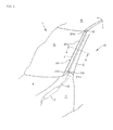
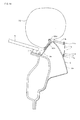
- Fig. 1 illustrates an airbag 20 of the present embodiment.
- the airbag 20 of the present embodiment is formed by folding back and stitching a sheet of a base cloth, and is composed of an expanding portion 20a, a pipe-connecting portion 20b, a first latching portion 20c, and a second latching portion 20c.
- the expanding portion 20a is a portion having an approximately elliptic shape, and absorbing an impact of a collision between a vehicle and an object of the collision, such as a pedestrian or the like at a time of expanding operation thereof.
- the pipe-connecting portion 20b is a portion protruding toward a direction perpendicular to a longitudinal direction of the expanding portion 20a, in which a pipe 16 is connected upon being inserted and swaged.
- the first latching portion 20c is a portion protruding in a direction perpendicular to the longitudinal direction of the expanding portion 20a in the vicinity of the pipe-connecting portion 20b, which is provided at a vehicle rear side in relation to the pipe-connecting portion 20b, and which latches the airbag 20 with a vehicle body.
- the second latching portion 20c is a portion provided at one end side of the expanding portion 20a of the airbag 20, which latches the airbag 20 with the vehicle body.
- Fig. 2 is a perspective view illustrating a vehicle on which the airbag apparatus 10 of the present embodiment is mounted
- Fig. 3 is a perspective view illustrating the vicinity of a front pillar 2 of the vehicle of the present embodiment
- Fig. 4 is a cross-sectional view taken along at line a-a in Fig. 3 .
- a numeral 1 denotes the vehicle
- a numeral 2 denotes the front pillar
- a numeral 3 denotes a fender
- a numeral 4 denotes a hood
- a numeral 5 denotes a roof
- a numeral 6 denotes a windshield
- a numeral 7 denotes a seal
- a numeral 10 denotes the airbag apparatus
- a numeral 11 denotes a cover
- a numeral 12 denotes a bag case
- numerals 13 and 14 denote anchors
- a numeral 15 denotes an inflator
- a numeral 16 denotes a pipe
- a numeral 20 denotes the airbag.
- the vehicle 1 includes a not-illustrated member, or the front pillar 2 that couples an engine room frame with the roof 5. Further, the vehicle 1 further includes the windshield 6 surrounded by the hood 4, the roof 5 and the front pillar 2, and attached thereto via the seal 7.
- the air bag apparatus 10 is housed on a windshield 6 side of the front pillar 2, and in the fender 3.
- the front pillar 2 includes a first surface 2a facing an outside of the vehicle 1 and a second surface 2b facing the windshield 6 side, and the airbag 20 is housed in the cover 11 on a second surface 2b side in a state of being folded back and housed in the bag case 12.
- the cover 11 is formed of member having an approximately L-shape in cross-section including an upper portion cover 11a and a first side portion cover 11b on the windshield 6 side, and is disposed so as to hide the airbag 20 that is folded back along the second surface 2b side of the front pillar 2.
- the folded-back airbag 20 may be directly housed in the cover 11 without being housed in the bag case 12.
- a first folded-back portion 11c on the windshield 6 side, and a second folded-back portion 11d on the front pillar 2 side are provided, and a cover-splash prevention member 17 such as a strap or the like is inserted into the second folded-back portion 11d and is swaged at several parts by means of bashing up the second folded-back portion 11d to an extent that does not damage the design.
- a cover-splash prevention member 17 such as a strap or the like is inserted into the second folded-back portion 11d and is swaged at several parts by means of bashing up the second folded-back portion 11d to an extent that does not damage the design.
- one end 17a of the cover-splash prevention member 17 is latched with the anchor 14, and the other end 17b thereof is latched on the vehicle body side such as the anchor 13, a root portion of the front pillar 2, a member, or the like.
- a seal 11e is attached, and this covers a gap between the front pillar 2 and the cover 11. This makes a design characteristic high.
- a long inflator 15 generating a gas for expanding the airbag 20 and blowing out the gas into an inside of the airbag 20, the pipe 16 that couples the airbag 20 with the inflator 15 and supplies the gas generated in the inflator 15 into the airbag 20, or the like are housed.
- the airbag 20, the inflator 15, the pipe 16, and the cover 11 are modularized.
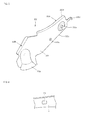
- Fig. 5 is a view illustrating a bag-expanding direction-limiting member 22
- Fig. 6 is a view of a part of the front pillar 2 looking from a windshield 6 side
- Fig. 7 is a perspective view illustrating the vicinity of the front pillar 2 where the cover 11, the airbag 20 and the fender 3 are omitted
- Fig. 8 is a cross-sectional view taken along a line b-b in Fig. 7 .
- the bag-expanding direction-limiting member 22 is formed to have an approximately L shape in cross-section, and is composed of a fixing portion 22A formed of a plate-shaped member and a hiding portion 22B for hiding a gap between the fender 3 and the windshield 6.
- the fixing portion 22A is provided with a vehicle body-fixing portion 22a that is fixed to the vehicle 1 with a screw or the like, a bag-fixing portion 22b for fixing the airbag 20, a side wall guide portion 22c rising up in a direction approximately perpendicular to the windshield 6, and an extension portion 22d extending approximately in parallel with the upper portion cover 11a from an end portion of the side wall guide portion 22c.
- a hooking portion 22e to be hooked on a latching hole 2a provided in the front pillar 2 illustrated in Fig. 6 is provided.
- the hiding portion 22B is provided with a continuous portion 22f that is allowed to communicate with the fixing portion 22A with a smooth curved surface following along the front pillar 2, and a curved portion 22g provided at an end portion on a side opposite to the fixing portion 22A, through which the pipe 16 passes.
- Fig. 7 and Fig. 8 illustrate a state in which the bag-expanding direction-limiting member 22 is attached to the vehicle 1.
- the bag-expanding direction-limiting member 22 hooks the hooking portion 22e illustrated in Fig. 5 on the latching hole 2a of the front pillar 2 illustrated in Fig. 6 , and fixes the vehicle body-fixing portion 22a to the vehicle 1 with a screw or the like.
- the fixing portion 22A is securely attached in a manner so as to be fitted along the front pillar 2.
- the hiding portion 22B is allowed to hide the gap between the fender 3 and the windshield 6, and to prevent the airbag 20 from hiding under the fender 3, and to guide the pipe 16 with the curved portion 22g.
- the airbag apparatus 10 illustrated in Fig. 3 and Fig. 4 is fixed after the bag-expanding direction-limiting member 22 is attached to the vehicle 1, and the cover 11 is closed, as illustrated in Fig. 8 .
- FIG. 9 is a view illustrating the folding back method for the airbag 20 of the present embodiment.
- Fig. 9(a) illustrates a step to fold back the expanding portion 20a of the airbag 20 illustrated in Fig. 1 into concertinas in parallel with a longitudinal direction thereof.
- the airbag 20 is folded back into concertinas along each bellows-folding line 20e extending approximately in parallel with the longitudinal direction
- a numeral 20f denotes a folding back area
- a numeral 20g denotes a folding back line
- a numeral 20A denotes a first expanding portion
- a numeral 20B denotes a second expanding portion.
- the first expanding portion 20A, the folding back area 20f, and the second expanding portion 20B are provided lining along a longitudinal direction
- the folding back line 20g is disposed in the folding back area 20f.
- Fig. 9(b) illustrates a step where the airbag 20 that is folded back into concertinas is folded back in the folding back area 20f that passes through the pipe-connecting portion 20b and extending in a direction perpendicular to the longitudinal direction, at a folding back line 20g.
- Fig. 9(c) illustrates a shape after the airbag 20 is folded back.
- the first expanding portion 20A and the second expanding portion 20B overlap with each other by means of folding back the airbag 20 as illustrated in Fig. 9(b) , and thereby a length of the airbag 20 in the longitudinal direction after being folded back is brought to be smaller than that before the airbag 20 is folded back. Further, since the airbag 20 is folded back at the folding back line 20g in the folding back area 20f in the vicinity of the pipe-connecting portion 20b, an interference with the pipe 16 can also be avoided when the airbag 20 is folded back.
- the step for folding back the airbag 20 into concertinas illustrated in Fig. 9(a) and a step for folding back the airbag 20 at the folding back line 20g illustrated in Fig. 9(b) may also be performed in a reversed order.
- Fig. 10 is a view illustrating the operation of the airbag apparatus 10 of the present embodiment
- Fig. 11 is a cross-sectional view illustrating a state when the airbag apparatus 10 is operated.
- the airbag apparatus 10 in a housed state as illustrated in Fig. 3 is operated by means of a control device or the like on the basis of a detection signal, in a case that the vehicle 1 collides with a not-illustrated object of the collision, and an impact force generated in the vehicle 1 is detected by means of a not-illustrated detecting device or the like.
- Fig. 10(a) illustrates an initial stage of an expanding operation, in which the airbag apparatus 10 starts to be operated, the gas flows into the airbag 20 through the pipe 16 from the inflator 15 that is housed in the fender 3 or the like, and the airbag 20 starts to be expanded.
- the airbag 20 starts to be expanded from a fender 3 side, and the cover 11 illustrated in Fig. 3 and Fig. 4 is opened by means of an expanding pressure.
- the second expanding portion 20B of the airbag 20 is installed on a front pillar 2 side in relation to a hinge portion 9 for opening and closing the hood 4 of the vehicle 1, or the hood 4 in a housed time, and starts to be expanded from the folded-back state.
- an expanding direction of the airbag 20 in a vehicle center direction is limited by means of the side wall guide portion 22c and the extension portion 22d of the bag-expanding direction-limiting member 22.
- a gap S between the cover 11 and the front pillar 2 is hidden and thereby there is no possibility that the airbag 20 is protruded from the gap S, and a stable operation can be performed.
- Fig. 10(b) illustrates an intermediate stage of the expanding operation, in which the gas flows into the airbag 20 through the pipe 16 from the inflator 15, and the airbag 20 continues to be expanded.
- the intermediate stage of the expanding operation an entire airbag 20 is completely exposed outward from a folded-back state.
- the airbag 20 intrudes into the engine room by means of the bag-expanding direction-limiting member 22. Moreover, since the airbag 20 starts to be expanded on the front pillar 2 side in relation to the hinge portion 9, or the hood 4 from the folded-back state, the interference with the fender 3, the hood 4, or the like can be reduced. Thereafter, the folded-back second expanding portion 20B starts to be expanded on the fender 3 and the hood 4 sides from the front pillar 2 side in a reversed manner by means of the expanding pressure.
- Fig. 10(c) illustrates a completion stage of the expanding operation, in which the expanding operation of the airbag 20 is completed.
- the airbag 20 is completely expanded.
- the folded-back second expanding portion 20B is configured to be expanded above the hinge portion 9.
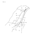
- Fig. 12 is a perspective view illustrating the vicinity of the front pillar 2 in the completion stage of the expanding operation
- Fig. 13 is a cross-sectional view taken along a line c-c in Fig. 12
- Fig. 14 is a cross-sectional view taken along a line d-d in Fig. 12
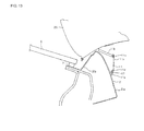
- Fig. 15 is a cross-sectional view taken along a line e-e in Fig. 12
- Fig. 16 is a perspective view illustrating the vicinity of the front pillar 2 in the completion stage of the expanding operation where the airbag 20 is omitted.
- the airbag 20 is developed in a direction along the front pillar 2 above a part of the fender 3 and the hood 4, and in front of the front pillar 2.
- the cover 11 is separated from the front pillar 2 by means of the pressure at the time of the expanding operation.
- the first expanding portion 20A of the airbag 20 is limited to be expanded in a direction in front of the front pillar 2 and to the vehicle center direction, which have a high possibility to collide with the object of the collision, such as the pedestrian or the like, by means of the side wall guide portion 22c and the extension portion 22d of the bag-expanding direction-limiting member 22.
- the second expanding portion 20B of the airbag 20 is expanded above the hinge portion 9 in a manner so as to cover the hinge portion 9 for opening and closing the hood 4 to a front member 8.
- the pipe 16 is omitted.
- the cover-splash prevention member 17 may be divided into a first cover-splash prevention member 17a that couples the anchor 14 with the cover 11 and a second cover-splash prevention member 17b that couples the anchor 13 with the cover 11.
- the cover 11 is separated from the vehicle 1 in a state of being coupled with the vehicle 1 via the cover-splash prevention member 17 at the time of expanding operation of the airbag 20, a load is hard to be applied to the cover 11, and a crack or a splash of the cover 11 can be prevented.
- the construction may be made such that the cover-splash prevention member 17 is latched on the vehicle body via other member.
- the airbag 20 In the completion stage of the expanding operation, since the airbag 20 is developed in a direction along the front pillar 2 in front of the front pillar 2, the airbag 20 can be developed to a wide area.
- the airbag apparatus 10 including the airbag 20, the inflator 15 blowing out the gas into the airbag 20, a pipe 16 for coupling the airbag 20 and the inflator 15, a detection device for detecting a collision, a control device for activating the inflator 15 by means of a signal from the detection device, and a cover 11 for housing the airbag 20, and expanding the airbag 20 disposed along the front pillar 2 at an outside of the vehicle
- the airbag 20 includes the first expanding portion 20A, the folding back area 20f, and the second expanding portion 20B lining in a longitudinal direction, and the first expanding portion 20A and the second expanding portion 20B are folded back at the folding back line 20g in the folding back area 20f, and are housed in an overlapping state. Accordingly, a housing space can be made small in comparison with an expanding area.
- the airbag 20 includes a pipe-connecting portion 20b to be connected with the pipe 16, and the folding back area 20f passes through the pipe-connecting portion 20b and extends in a direction perpendicular to the longitudinal direction, the interference with the pipe 16 at the time when the airbag 20 is folded back can be reduced, and the airbag 20 can be efficiently folded back.
- the second expanding portion 20B of the airbag 20 is installed on the front pillar 2 side in relation to the hinge portion 9 for opening and closing the hood 4 of the vehicle 1 when housed, and is installed so as to expand above the hinge portion 9 when expanded, the second expanding portion 20B can be housed in a small space, and the airbag 20 can cover the portion where an impact at a time of a secondary collision cannot be absorbed only by an energy-absorbing effect of the hood, even though the airbag is that of a compact-sized.
- the second expanding portion 20B of the airbag 20 is installed on the front pillar 2 side in relation to the hood 4 when housed, the second expanding portion 20B of the airbag 20 can be housed in a further small space.
- a housing space can be made small in comparison with an expanding area. Further, the airbag 20 can cover a portion where an impact at a time of a secondary collision cannot be absorbed only by an energy-absorbing effect of a hood even though the airbag 20 is that of the compact-sized.
Landscapes
- Engineering & Computer Science (AREA)
- Mechanical Engineering (AREA)
- Air Bags (AREA)
- Superstructure Of Vehicle (AREA)
- Body Structure For Vehicles (AREA)
Abstract
Description
- The present invention belongs to a technical field of an airbag apparatus for absorbing an impact applied to an object of a collision, or a vehicle, while expanding and developing to an outside of the vehicle by means of a gas from an inflator or the like, in an emergency such as a case when the vehicle collides with the object of the collision, or the like.
- Hitherto, an airbag apparatus that absorbs an impact generated by re-collision between a pedestrian or the like and a vehicle, by means of causing the airbag to expand to an outside of a pillar portion of the vehicle at a time of collision between the vehicle and the pedestrian or the like, is known.
- For example, an airbag apparatus, in which a vertically long tubular airbag is expanded and developed from the vicinity of a lower end portion of a front pillar toward an upper side along an outside surface of the front pillar, is disclosed (refer to
JP-A-2003-306099 - Further, s pillar airbag apparatus in which an inflator is activated upon receiving a collision detection signal from a pedestrian collision detection device, and a hood airbag and a pillar airbag are expanded and developed is disclosed (refer to
JP-A-7-108903 - However, the airbag apparatus described in the
Patent Document 1 had a structure that only covers the front pillar, and was not provided with an airbag for covering an upper part of a hood. Accordingly, a portion where an impact at a time of a secondary collision cannot be absorbed only by an energy-absorbing effect of the hood, for example, an upper part of a hinge portion for opening and closing the hood could not be covered. - Furthermore, the airbag apparatus described in the
Patent Document 2 has a structure where the upper part of the hood is covered by the airbag. However, in this case, both of the airbag for the front pillar and the airbag for the hood are required to be installed. This requires a wide space, and the airbag grows in size, resulting in high cost. - The present invention is made in light of the above-described problems, and the object of the present invention is to provide an airbag apparatus capable of being housed in a small space, and absorbing the impact at the time of the secondary collision in a wide area even though the airbag is that of a compact-sized.
- In order to solve the above described problems, the invention according to
Claim 1 is characterized in that in an airbag apparatus including an airbag, an inflator blowing out a gas into an inside of the aforementioned airbag, a pipe for coupling the airbag with the aforementioned inflator, a detection device for detecting a collision, a control device for activating the inflator according to a signal from the detection device, and a cover for housing the airbag, and expanding the airbag disposed along a front pillar at an outside of a vehicle, the aforementioned airbag includes a first expanding portion, a folding back area, and a second expanding portion lining in a longitudinal direction, and the aforementioned first expanding portion and the aforementioned second expanding portion are folded back at a folding back line in the aforementioned folding back area, and housed in an overlapping state. - The invention according to
Claim 2 is characterized in that the aforementioned airbag includes a pipe-connecting portion to be connected with the aforementioned pipe, and the folding back area passes through the pipe-connecting portion and extends in a direction perpendicular to the aforementioned longitudinal direction. - The invention according to
Claim 3 is characterized in that the aforementioned second expanding portion of the aforementioned airbag is installed on the aforementioned front pillar side relative to a hinge portion for opening and closing a hood of the aforementioned vehicle when being housed, and when being expanded, the second expanding portion of the airbag is installed in a manner so as to be expanded above the aforementioned hinge portion. - The invention according to
Claim 4 is characterized in that the aforementioned second expanding portion of the aforementioned airbag is installed on the aforementioned front pillar side relative to the hood when being housed. - According to the thus constructed airbag apparatus with respect to the present invention, in the airbag apparatus including an airbag, an inflator blowing out a gas into an inside of the aforementioned airbag, a pipe for coupling the airbag with the inflator, a detection device for detecting a collision, a control device for activating the inflator according to a signal from the aforementioned detection device, and a cover for housing the aforementioned airbag, and expanding the aforementioned airbag disposed along a front pillar at an outside of a vehicle, since the aforementioned airbag includes a first expanding portion, a folding back area, and a second expanding portion lining in a longitudinal direction, and the aforementioned first expanding portion and the aforementioned second expanding portion are folded back at a folding back line in the aforementioned folding back area, and housed in an overlapping state, a housing space can be made small in comparison with an expanding area.
- Further, since the aforementioned airbag includes a pipe-connecting portion to be connected to the aforementioned pipe, and the aforementioned folding back area passes through the aforementioned pipe-connecting portion, and extends in a direction perpendicular to the aforementioned longitudinal direction, an interference with the pipe can be reduced and the airbag can be efficiently folded back when the airbag is folded back.
- Furthermore, since the aforementioned second expanding portion of the aforementioned airbag is installed on the aforementioned front pillar side relative to a hinge portion for opening and closing a hood of the aforementioned vehicle when being housed, and when being expanded, the second expanding portion of the airbag is installed in a manner so as to be expanded above the aforementioned hinge portion, the second expanding portion of the airbag can be housed in a small space, and can cover the portion where an impact at a time of a secondary collision cannot be absorbed only by an energy-absorbing effect of the hood, even though the airbag is that of a compact-sized.
- Moreover, since the aforementioned second expanding portion of the aforementioned airbag is, when being housed, installed on the aforementioned front pillar side relative to the aforementioned hood, the second expanding portion can be housed in a further small space.
- Hereinbelow, an embodiment of the present invention will be explained with reference to the drawings:
-
Fig. 1 is a view illustrating an embodiment of an airbag with respect to the present invention; -
Fig. 2 is a perspective view illustrating a vehicle on which an airbag apparatus of the present embodiment is mounted; -
Fig. 3 is a perspective view illustrating the vicinity of the front pillar of the vehicle of the present embodiment; -
Fig. 4 is a cross-sectional view taken along a line a-a inFig. 3 ; -
Fig. 5 is a view illustrating a bag-expanding direction-limiting member; -
Fig. 6 is a view illustrating a part of the front pillar looking from a windshield side; -
Fig. 7 is a perspective view illustrating the vicinity of the front pillar in which a cover, the airbag, and a fender are omitted; -
Fig. 8 is a cross-sectional view taken along a line b-b inFig. 7 ; -
Fig. 9 is a view illustrating a folding back method for theairbag 20 of the present embodiment; -
Fig. 10 is a view illustrating an operation of the airbag apparatus of the present embodiment; -
Fig. 11 is a cross-sectional view illustrating a state when theairbag apparatus 10 is operated; -
Fig. 12 is a perspective view illustrating the vicinity of the front pillar in a completion stage of an expanding operation; -
Fig. 13 is a cross-sectional view taken along a line c-c inFig. 12 ; -
Fig. 14 is a cross-sectional view taken along a line d-d inFig. 12 ; -
Fig. 15 is a cross-sectional view taken along a line e-e inFig. 12 ; and -
Fig. 16 is a perspective view illustrating the vicinity of the front pillar in which the airbag in the completion stage of the expanding operation is omitted. -
Fig. 1 illustrates anairbag 20 of the present embodiment. Theairbag 20 of the present embodiment is formed by folding back and stitching a sheet of a base cloth, and is composed of an expandingportion 20a, a pipe-connectingportion 20b, afirst latching portion 20c, and asecond latching portion 20c. The expandingportion 20a is a portion having an approximately elliptic shape, and absorbing an impact of a collision between a vehicle and an object of the collision, such as a pedestrian or the like at a time of expanding operation thereof. The pipe-connectingportion 20b is a portion protruding toward a direction perpendicular to a longitudinal direction of the expandingportion 20a, in which apipe 16 is connected upon being inserted and swaged. Thefirst latching portion 20c is a portion protruding in a direction perpendicular to the longitudinal direction of the expandingportion 20a in the vicinity of the pipe-connectingportion 20b, which is provided at a vehicle rear side in relation to the pipe-connectingportion 20b, and which latches theairbag 20 with a vehicle body. Thesecond latching portion 20c is a portion provided at one end side of the expandingportion 20a of theairbag 20, which latches theairbag 20 with the vehicle body. - Next, a state in which an
airbag apparatus 10 including theairbag 20 is mounted on avehicle 1 will be explained. -
Fig. 2 is a perspective view illustrating a vehicle on which theairbag apparatus 10 of the present embodiment is mounted,Fig. 3 is a perspective view illustrating the vicinity of afront pillar 2 of the vehicle of the present embodiment, andFig. 4 is a cross-sectional view taken along at line a-a inFig. 3 . - In the drawings, a
numeral 1 denotes the vehicle, anumeral 2 denotes the front pillar, anumeral 3 denotes a fender, anumeral 4 denotes a hood, anumeral 5 denotes a roof, anumeral 6 denotes a windshield, anumeral 7 denotes a seal, anumeral 10 denotes the airbag apparatus, anumeral 11 denotes a cover, anumeral 12 denotes a bag case,numerals numeral 15 denotes an inflator, anumeral 16 denotes a pipe, and anumeral 20 denotes the airbag. - The
vehicle 1 includes a not-illustrated member, or thefront pillar 2 that couples an engine room frame with theroof 5. Further, thevehicle 1 further includes thewindshield 6 surrounded by thehood 4, theroof 5 and thefront pillar 2, and attached thereto via theseal 7. - The
air bag apparatus 10 is housed on awindshield 6 side of thefront pillar 2, and in thefender 3. Thefront pillar 2 includes afirst surface 2a facing an outside of thevehicle 1 and asecond surface 2b facing thewindshield 6 side, and theairbag 20 is housed in thecover 11 on asecond surface 2b side in a state of being folded back and housed in thebag case 12. - The
cover 11 is formed of member having an approximately L-shape in cross-section including an upper portion cover 11a and a first side portion cover 11b on thewindshield 6 side, and is disposed so as to hide theairbag 20 that is folded back along thesecond surface 2b side of thefront pillar 2. Incidentally, the folded-back airbag 20 may be directly housed in thecover 11 without being housed in thebag case 12. - In the
cover 11, a first folded-back portion 11c on thewindshield 6 side, and a second folded-back portion 11d on thefront pillar 2 side are provided, and a cover-splash prevention member 17 such as a strap or the like is inserted into the second folded-back portion 11d and is swaged at several parts by means of bashing up the second folded-back portion 11d to an extent that does not damage the design. As described later, one end 17a of the cover-splash prevention member 17 is latched with theanchor 14, and theother end 17b thereof is latched on the vehicle body side such as theanchor 13, a root portion of thefront pillar 2, a member, or the like. - In the vicinity of the second folded-
back portion 11d of the upper portion cover 11a, aseal 11e is attached, and this covers a gap between thefront pillar 2 and thecover 11. This makes a design characteristic high. - Below the
fender 3 or thehood 4, along inflator 15 generating a gas for expanding theairbag 20 and blowing out the gas into an inside of theairbag 20, thepipe 16 that couples theairbag 20 with theinflator 15 and supplies the gas generated in theinflator 15 into theairbag 20, or the like are housed. - Incidentally, it is preferable that the
airbag 20, theinflator 15, thepipe 16, and thecover 11 are modularized. -
Fig. 5 is a view illustrating a bag-expanding direction-limitingmember 22,Fig. 6 is a view of a part of thefront pillar 2 looking from awindshield 6 side,Fig. 7 is a perspective view illustrating the vicinity of thefront pillar 2 where thecover 11, theairbag 20 and thefender 3 are omitted, andFig. 8 is a cross-sectional view taken along a line b-b inFig. 7 . - As illustrated in
Fig. 5 , the bag-expanding direction-limitingmember 22 is formed to have an approximately L shape in cross-section, and is composed of afixing portion 22A formed of a plate-shaped member and ahiding portion 22B for hiding a gap between thefender 3 and thewindshield 6. Thefixing portion 22A is provided with a vehicle body-fixing portion 22a that is fixed to thevehicle 1 with a screw or the like, a bag-fixing portion 22b for fixing theairbag 20, a sidewall guide portion 22c rising up in a direction approximately perpendicular to thewindshield 6, and anextension portion 22d extending approximately in parallel with the upper portion cover 11a from an end portion of the sidewall guide portion 22c. Further, in the sidewall guide portion 22c, a hookingportion 22e to be hooked on alatching hole 2a provided in thefront pillar 2 illustrated inFig. 6 is provided. Thehiding portion 22B is provided with acontinuous portion 22f that is allowed to communicate with thefixing portion 22A with a smooth curved surface following along thefront pillar 2, and acurved portion 22g provided at an end portion on a side opposite to thefixing portion 22A, through which thepipe 16 passes. -
Fig. 7 andFig. 8 illustrate a state in which the bag-expanding direction-limitingmember 22 is attached to thevehicle 1. The bag-expanding direction-limitingmember 22 hooks the hookingportion 22e illustrated inFig. 5 on thelatching hole 2a of thefront pillar 2 illustrated inFig. 6 , and fixes the vehicle body-fixing portion 22a to thevehicle 1 with a screw or the like. At this moment, thefixing portion 22A is securely attached in a manner so as to be fitted along thefront pillar 2. Thehiding portion 22B is allowed to hide the gap between thefender 3 and thewindshield 6, and to prevent theairbag 20 from hiding under thefender 3, and to guide thepipe 16 with thecurved portion 22g. - As described above, the
airbag apparatus 10 illustrated inFig. 3 andFig. 4 is fixed after the bag-expanding direction-limitingmember 22 is attached to thevehicle 1, and thecover 11 is closed, as illustrated inFig. 8 . - Next, a folding back method for the
airbag 20 of the present embodiment will be explained.Fig. 9 is a view illustrating the folding back method for theairbag 20 of the present embodiment. -
Fig. 9(a) illustrates a step to fold back the expandingportion 20a of theairbag 20 illustrated inFig. 1 into concertinas in parallel with a longitudinal direction thereof. In this step, theairbag 20 is folded back into concertinas along each bellows-foldingline 20e extending approximately in parallel with the longitudinal direction Incidentally, although described later, a numeral 20f denotes a folding back area, a numeral 20g denotes a folding back line, a numeral 20A denotes a first expanding portion, and a numeral 20B denotes a second expanding portion. The first expandingportion 20A, the folding backarea 20f, and the second expandingportion 20B are provided lining along a longitudinal direction, and the folding backline 20g is disposed in the folding backarea 20f. -
Fig. 9(b) illustrates a step where theairbag 20 that is folded back into concertinas is folded back in the folding backarea 20f that passes through the pipe-connectingportion 20b and extending in a direction perpendicular to the longitudinal direction, at a folding backline 20g. -
Fig. 9(c) illustrates a shape after theairbag 20 is folded back. The first expandingportion 20A and the second expandingportion 20B overlap with each other by means of folding back theairbag 20 as illustrated inFig. 9(b) , and thereby a length of theairbag 20 in the longitudinal direction after being folded back is brought to be smaller than that before theairbag 20 is folded back. Further, since theairbag 20 is folded back at the folding backline 20g in the folding backarea 20f in the vicinity of the pipe-connectingportion 20b, an interference with thepipe 16 can also be avoided when theairbag 20 is folded back. - Incidentally, the step for folding back the
airbag 20 into concertinas illustrated inFig. 9(a) and a step for folding back theairbag 20 at the folding backline 20g illustrated inFig. 9(b) may also be performed in a reversed order. - Next, an operation of the
airbag apparatus 10 of the present embodiment will be explained.Fig. 10 is a view illustrating the operation of theairbag apparatus 10 of the present embodiment, andFig. 11 is a cross-sectional view illustrating a state when theairbag apparatus 10 is operated. - The
airbag apparatus 10 in a housed state as illustrated inFig. 3 , is operated by means of a control device or the like on the basis of a detection signal, in a case that thevehicle 1 collides with a not-illustrated object of the collision, and an impact force generated in thevehicle 1 is detected by means of a not-illustrated detecting device or the like. -
Fig. 10(a) illustrates an initial stage of an expanding operation, in which theairbag apparatus 10 starts to be operated, the gas flows into theairbag 20 through thepipe 16 from the inflator 15 that is housed in thefender 3 or the like, and theairbag 20 starts to be expanded. In the initial stage of the expanding operation, theairbag 20 starts to be expanded from afender 3 side, and thecover 11 illustrated inFig. 3 andFig. 4 is opened by means of an expanding pressure. - At this moment, as illustrated in
Fig. 9(c) , the second expandingportion 20B of theairbag 20 is installed on afront pillar 2 side in relation to ahinge portion 9 for opening and closing thehood 4 of thevehicle 1, or thehood 4 in a housed time, and starts to be expanded from the folded-back state. - Furthermore, as illustrated in
Fig. 11 , an expanding direction of theairbag 20 in a vehicle center direction is limited by means of the sidewall guide portion 22c and theextension portion 22d of the bag-expanding direction-limitingmember 22. As a result, a gap S between thecover 11 and thefront pillar 2 is hidden and thereby there is no possibility that theairbag 20 is protruded from the gap S, and a stable operation can be performed. -
Fig. 10(b) illustrates an intermediate stage of the expanding operation, in which the gas flows into theairbag 20 through thepipe 16 from the inflator 15, and theairbag 20 continues to be expanded. In the intermediate stage of the expanding operation, anentire airbag 20 is completely exposed outward from a folded-back state. - At this moment, there is no possibility that the
airbag 20 intrudes into the engine room by means of the bag-expanding direction-limitingmember 22. Moreover, since theairbag 20 starts to be expanded on thefront pillar 2 side in relation to thehinge portion 9, or thehood 4 from the folded-back state, the interference with thefender 3, thehood 4, or the like can be reduced. Thereafter, the folded-back second expandingportion 20B starts to be expanded on thefender 3 and thehood 4 sides from thefront pillar 2 side in a reversed manner by means of the expanding pressure. -
Fig. 10(c) illustrates a completion stage of the expanding operation, in which the expanding operation of theairbag 20 is completed. In the completion stage of the expanding operation, theairbag 20 is completely expanded. At this moment, the folded-back second expandingportion 20B is configured to be expanded above thehinge portion 9. - A state of the
airbag apparatus 10 in the completion stage of the expanding operation will be explained below in detail. -
Fig. 12 is a perspective view illustrating the vicinity of thefront pillar 2 in the completion stage of the expanding operation,Fig. 13 is a cross-sectional view taken along a line c-c inFig. 12 ,Fig. 14 is a cross-sectional view taken along a line d-d inFig. 12 ,Fig. 15 is a cross-sectional view taken along a line e-e inFig. 12 , andFig. 16 is a perspective view illustrating the vicinity of thefront pillar 2 in the completion stage of the expanding operation where theairbag 20 is omitted. - In the completion stage of the expanding operation, the
airbag 20 is developed in a direction along thefront pillar 2 above a part of thefender 3 and thehood 4, and in front of thefront pillar 2. - As illustrated in
Fig. 13 , in the completion stage, thecover 11 is separated from thefront pillar 2 by means of the pressure at the time of the expanding operation. - Further, as illustrated in
Fig. 14 , in the completion stage, the first expandingportion 20A of theairbag 20 is limited to be expanded in a direction in front of thefront pillar 2 and to the vehicle center direction, which have a high possibility to collide with the object of the collision, such as the pedestrian or the like, by means of the sidewall guide portion 22c and theextension portion 22d of the bag-expanding direction-limitingmember 22. - Furthermore, as illustrated in
Fig. 15 , in the completion stage, the second expandingportion 20B of theairbag 20 is expanded above thehinge portion 9 in a manner so as to cover thehinge portion 9 for opening and closing thehood 4 to a front member 8. Incidentally, inFig. 15 , thepipe 16 is omitted. - At this moment, as illustrated in
Fig. 16 , since thecover 11 is latched on thevehicle body 1 side by means of the cover-splash prevention member 17 via theanchors cover 11 is splashed from thevehicle 1. Incidentally, the cover-splash prevention member 17 may be divided into a first cover-splash prevention member 17a that couples theanchor 14 with thecover 11 and a second cover-splash prevention member 17b that couples theanchor 13 with thecover 11. - As described above, since the
cover 11 is separated from thevehicle 1 in a state of being coupled with thevehicle 1 via the cover-splash prevention member 17 at the time of expanding operation of theairbag 20, a load is hard to be applied to thecover 11, and a crack or a splash of thecover 11 can be prevented. - Incidentally, in this embodiment, although the cover-
splash prevention member 17 is latched on theanchors airbag 20, the construction may be made such that the cover-splash prevention member 17 is latched on the vehicle body via other member. - In the completion stage of the expanding operation, since the
airbag 20 is developed in a direction along thefront pillar 2 in front of thefront pillar 2, theairbag 20 can be developed to a wide area. - According to the thus constructed
airbag apparatus 10 with respect to the present invention, in theairbag apparatus 10 including theairbag 20, the inflator 15 blowing out the gas into theairbag 20, apipe 16 for coupling theairbag 20 and the inflator 15, a detection device for detecting a collision, a control device for activating the inflator 15 by means of a signal from the detection device, and acover 11 for housing theairbag 20, and expanding theairbag 20 disposed along thefront pillar 2 at an outside of the vehicle, theairbag 20 includes the first expandingportion 20A, the folding backarea 20f, and the second expandingportion 20B lining in a longitudinal direction, and the first expandingportion 20A and the second expandingportion 20B are folded back at the folding backline 20g in the folding backarea 20f, and are housed in an overlapping state. Accordingly, a housing space can be made small in comparison with an expanding area. - Further, since the
airbag 20 includes a pipe-connectingportion 20b to be connected with thepipe 16, and the folding backarea 20f passes through the pipe-connectingportion 20b and extends in a direction perpendicular to the longitudinal direction, the interference with thepipe 16 at the time when theairbag 20 is folded back can be reduced, and theairbag 20 can be efficiently folded back. - Furthermore, since the second expanding
portion 20B of theairbag 20 is installed on thefront pillar 2 side in relation to thehinge portion 9 for opening and closing thehood 4 of thevehicle 1 when housed, and is installed so as to expand above thehinge portion 9 when expanded, the second expandingportion 20B can be housed in a small space, and theairbag 20 can cover the portion where an impact at a time of a secondary collision cannot be absorbed only by an energy-absorbing effect of the hood, even though the airbag is that of a compact-sized. - Moreover, since the second expanding
portion 20B of theairbag 20 is installed on thefront pillar 2 side in relation to thehood 4 when housed, the second expandingportion 20B of theairbag 20 can be housed in a further small space. - According to the thus constructed airbag apparatus with respect to the present invention, a housing space can be made small in comparison with an expanding area. Further, the
airbag 20 can cover a portion where an impact at a time of a secondary collision cannot be absorbed only by an energy-absorbing effect of a hood even though theairbag 20 is that of the compact-sized.
Claims (4)
- An airbag apparatus comprising:an airbag;an inflator blowing out a gas into an inside of the airbag;a pipe for coupling the airbag with the inflator;a detection device for detecting a collision;a control device for activating the inflator according to a signal from the detection device; anda cover for housing the airbag, and expanding the airbag disposed along a front pillar at an outside of a vehicle,wherein the airbag includes a first expanding portion, a folding back area, and a second expanding portion lining in a longitudinal direction, andwherein the first expanding portion and the second expanding portion are folded back at a folding back line in the folding back area, and housed in an overlapping state.
- The airbag apparatus according to Claim 1 wherein the airbag includes a pipe-connecting portion to be connected with the pipe, and the folding back area passes through the pipe-connecting portion and extends in a direction perpendicular to the longitudinal direction.
- The airbag apparatus according to Claim 1 or 2, wherein the second expanding portion of the airbag is installed on the front pillar side relative to a hinge portion for opening and closing a hood of the vehicle when being housed, and when being expanded, the second expanding portion of the airbag is installed in a manner so as to be expanded above the hinge portion.
- The airbag apparatus according to any one of Claims 1 through 3, wherein the second expanding portion of the airbag is installed on the front pillar side relative to the hood when being housed.
Applications Claiming Priority (1)
| Application Number | Priority Date | Filing Date | Title |
|---|---|---|---|
| JP2008026112A JP5000542B2 (en) | 2008-02-06 | 2008-02-06 | Airbag device |
Publications (2)
| Publication Number | Publication Date |
|---|---|
| EP2088038A1 true EP2088038A1 (en) | 2009-08-12 |
| EP2088038B1 EP2088038B1 (en) | 2011-01-12 |
Family
ID=40578363
Family Applications (1)
| Application Number | Title | Priority Date | Filing Date |
|---|---|---|---|
| EP08170039A Ceased EP2088038B1 (en) | 2008-02-06 | 2008-11-27 | Airbag apparatus |
Country Status (3)
| Country | Link |
|---|---|
| EP (1) | EP2088038B1 (en) |
| JP (1) | JP5000542B2 (en) |
| DE (1) | DE602008004426D1 (en) |
Families Citing this family (2)
| Publication number | Priority date | Publication date | Assignee | Title |
|---|---|---|---|---|
| KR102951355B1 (en) * | 2021-03-24 | 2026-04-09 | 현대모비스 주식회사 | Air bag apparatus for protecting pedestrian |
| KR102676350B1 (en) * | 2021-05-24 | 2024-06-17 | 현대모비스 주식회사 | Cushion for pedestrian air-bag |
Citations (4)
| Publication number | Priority date | Publication date | Assignee | Title |
|---|---|---|---|---|
| WO2002079009A1 (en) * | 2001-03-29 | 2002-10-10 | Toyota Jidosha Kabushiki Kaisha | Airbag apparatus for pedestrian protection |
| JP2005096686A (en) * | 2003-09-26 | 2005-04-14 | Toyota Motor Corp | Pillar airbag device |
| JP2006298150A (en) * | 2005-04-20 | 2006-11-02 | Toyota Motor Corp | Airbag device |
| EP2050632A2 (en) * | 2007-10-16 | 2009-04-22 | Takata Corporation | Airbag apparatus |
Family Cites Families (2)
| Publication number | Priority date | Publication date | Assignee | Title |
|---|---|---|---|---|
| JP2003252138A (en) * | 2002-02-26 | 2003-09-10 | Toyoda Gosei Co Ltd | Pedestrian airbag device |
| JP2006088851A (en) * | 2004-09-22 | 2006-04-06 | Toyoda Gosei Co Ltd | Method of folding up airbag and airbag device |
-
2008
- 2008-02-06 JP JP2008026112A patent/JP5000542B2/en not_active Expired - Fee Related
- 2008-11-27 DE DE602008004426T patent/DE602008004426D1/en active Active
- 2008-11-27 EP EP08170039A patent/EP2088038B1/en not_active Ceased
Patent Citations (4)
| Publication number | Priority date | Publication date | Assignee | Title |
|---|---|---|---|---|
| WO2002079009A1 (en) * | 2001-03-29 | 2002-10-10 | Toyota Jidosha Kabushiki Kaisha | Airbag apparatus for pedestrian protection |
| JP2005096686A (en) * | 2003-09-26 | 2005-04-14 | Toyota Motor Corp | Pillar airbag device |
| JP2006298150A (en) * | 2005-04-20 | 2006-11-02 | Toyota Motor Corp | Airbag device |
| EP2050632A2 (en) * | 2007-10-16 | 2009-04-22 | Takata Corporation | Airbag apparatus |
Also Published As
| Publication number | Publication date |
|---|---|
| JP5000542B2 (en) | 2012-08-15 |
| DE602008004426D1 (en) | 2011-02-24 |
| JP2009184490A (en) | 2009-08-20 |
| EP2088038B1 (en) | 2011-01-12 |
Similar Documents
| Publication | Publication Date | Title |
|---|---|---|
| US7607685B2 (en) | Automobile side airbag guide plate | |
| CN105829171B (en) | Pedestrian protection airbag device for vehicle | |
| JP5038089B2 (en) | Airbag device | |
| EP1937519B1 (en) | Airbag device | |
| US7921957B2 (en) | Hood airbag device | |
| RU2673417C1 (en) | Car side part design | |
| EP2088038B1 (en) | Airbag apparatus | |
| EP2105358A1 (en) | Airbag device | |
| EP2050632A2 (en) | Airbag apparatus | |
| JP2000198407A (en) | Installation structure of vehicle occupant protection system | |
| JP5179336B2 (en) | Airbag device | |
| EP2050635B1 (en) | Airbag apparatus | |
| JP2006205934A (en) | Air bag and non-occupant protection device | |
| EP2070778A1 (en) | Airbag apparatus | |
| JP4889744B2 (en) | Safety system | |
| JP5030809B2 (en) | Airbag device | |
| JP5030806B2 (en) | Airbag device | |
| JP5983441B2 (en) | Air bag folding method for pedestrian airbag device | |
| JP5145173B2 (en) | Airbag device | |
| JP4345579B2 (en) | Pedestrian airbag device | |
| JP5145145B2 (en) | Airbag device | |
| KR100581968B1 (en) | Installation structure of loop rail airbag for automobile | |
| JP2009161164A (en) | Airbag device | |
| JP2011000996A (en) | Airbag device | |
| EP2072349A2 (en) | Airbag device |
Legal Events
| Date | Code | Title | Description |
|---|---|---|---|
| PUAI | Public reference made under article 153(3) epc to a published international application that has entered the european phase |
Free format text: ORIGINAL CODE: 0009012 |
|
| AK | Designated contracting states |
Kind code of ref document: A1 Designated state(s): AT BE BG CH CY CZ DE DK EE ES FI FR GB GR HR HU IE IS IT LI LT LU LV MC MT NL NO PL PT RO SE SI SK TR |
|
| AX | Request for extension of the european patent |
Extension state: AL BA MK RS |
|
| 17P | Request for examination filed |
Effective date: 20100112 |
|
| AKX | Designation fees paid |
Designated state(s): DE GB |
|
| GRAP | Despatch of communication of intention to grant a patent |
Free format text: ORIGINAL CODE: EPIDOSNIGR1 |
|
| GRAS | Grant fee paid |
Free format text: ORIGINAL CODE: EPIDOSNIGR3 |
|
| GRAA | (expected) grant |
Free format text: ORIGINAL CODE: 0009210 |
|
| AK | Designated contracting states |
Kind code of ref document: B1 Designated state(s): DE GB |
|
| REG | Reference to a national code |
Ref country code: GB Ref legal event code: FG4D |
|
| REF | Corresponds to: |
Ref document number: 602008004426 Country of ref document: DE Date of ref document: 20110224 Kind code of ref document: P |
|
| REG | Reference to a national code |
Ref country code: DE Ref legal event code: R096 Ref document number: 602008004426 Country of ref document: DE Effective date: 20110224 |
|
| PLBE | No opposition filed within time limit |
Free format text: ORIGINAL CODE: 0009261 |
|
| STAA | Information on the status of an ep patent application or granted ep patent |
Free format text: STATUS: NO OPPOSITION FILED WITHIN TIME LIMIT |
|
| 26N | No opposition filed |
Effective date: 20111013 |
|
| REG | Reference to a national code |
Ref country code: DE Ref legal event code: R097 Ref document number: 602008004426 Country of ref document: DE Effective date: 20111013 |
|
| PGFP | Annual fee paid to national office [announced via postgrant information from national office to epo] |
Ref country code: GB Payment date: 20131127 Year of fee payment: 6 |
|
| GBPC | Gb: european patent ceased through non-payment of renewal fee |
Effective date: 20141127 |
|
| PG25 | Lapsed in a contracting state [announced via postgrant information from national office to epo] |
Ref country code: GB Free format text: LAPSE BECAUSE OF NON-PAYMENT OF DUE FEES Effective date: 20141127 |
|
| REG | Reference to a national code |
Ref country code: DE Ref legal event code: R082 Ref document number: 602008004426 Country of ref document: DE Representative=s name: VOSSIUS & PARTNER PATENTANWAELTE RECHTSANWAELT, DE Ref country code: DE Ref legal event code: R081 Ref document number: 602008004426 Country of ref document: DE Owner name: JOYSON SAFETY SYSTEMS JAPAN K.K., JP Free format text: FORMER OWNER: TAKATA CORP., TOKIO/TOKYO, JP |
|
| PGFP | Annual fee paid to national office [announced via postgrant information from national office to epo] |
Ref country code: DE Payment date: 20181120 Year of fee payment: 11 |
|
| REG | Reference to a national code |
Ref country code: DE Ref legal event code: R119 Ref document number: 602008004426 Country of ref document: DE |
|
| PG25 | Lapsed in a contracting state [announced via postgrant information from national office to epo] |
Ref country code: DE Free format text: LAPSE BECAUSE OF NON-PAYMENT OF DUE FEES Effective date: 20200603 |