EP2087875B1 - Toilet unit for use in a supine position - Google Patents
Toilet unit for use in a supine position Download PDFInfo
- Publication number
- EP2087875B1 EP2087875B1 EP08291039A EP08291039A EP2087875B1 EP 2087875 B1 EP2087875 B1 EP 2087875B1 EP 08291039 A EP08291039 A EP 08291039A EP 08291039 A EP08291039 A EP 08291039A EP 2087875 B1 EP2087875 B1 EP 2087875B1
- Authority
- EP
- European Patent Office
- Prior art keywords
- urination
- nozzle
- section
- defecation
- casing
- Prior art date
- Legal status (The legal status is an assumption and is not a legal conclusion. Google has not performed a legal analysis and makes no representation as to the accuracy of the status listed.)
- Not-in-force
Links
Images


Classifications
-
- A—HUMAN NECESSITIES
- A61—MEDICAL OR VETERINARY SCIENCE; HYGIENE
- A61G—TRANSPORT, PERSONAL CONVEYANCES, OR ACCOMMODATION SPECIALLY ADAPTED FOR PATIENTS OR DISABLED PERSONS; OPERATING TABLES OR CHAIRS; CHAIRS FOR DENTISTRY; FUNERAL DEVICES
- A61G9/00—Bed-pans, urinals or other sanitary devices for bed-ridden persons; Cleaning devices therefor, e.g. combined with toilet-urinals
-
- A—HUMAN NECESSITIES
- A61—MEDICAL OR VETERINARY SCIENCE; HYGIENE
- A61G—TRANSPORT, PERSONAL CONVEYANCES, OR ACCOMMODATION SPECIALLY ADAPTED FOR PATIENTS OR DISABLED PERSONS; OPERATING TABLES OR CHAIRS; CHAIRS FOR DENTISTRY; FUNERAL DEVICES
- A61G2203/00—General characteristics of devices
- A61G2203/30—General characteristics of devices characterised by sensor means
- A61G2203/46—General characteristics of devices characterised by sensor means for temperature
-
- A—HUMAN NECESSITIES
- A61—MEDICAL OR VETERINARY SCIENCE; HYGIENE
- A61G—TRANSPORT, PERSONAL CONVEYANCES, OR ACCOMMODATION SPECIALLY ADAPTED FOR PATIENTS OR DISABLED PERSONS; OPERATING TABLES OR CHAIRS; CHAIRS FOR DENTISTRY; FUNERAL DEVICES
- A61G7/00—Beds specially adapted for nursing; Devices for lifting patients or disabled persons
- A61G7/02—Beds specially adapted for nursing; Devices for lifting patients or disabled persons with toilet conveniences, or specially adapted for use with toilets
Definitions
- the present invention relates to a toilet unit for use in supine position whereby a bed-ridden patient and/or an aged person can treat his urination and defecation in a supine position without someone else's assistance.
- Patent Document 1 discloses a technique in which a urination and defecation treating body of a substantially L-shape as seen from the side is provided with a stool detection sensor and various nozzles.
- the stools detection sensor consisting of a proximity sensor detects the stools to automatically cause wash water to spout through various nozzles, thereby washing not only the private parts, but also the inside of the urination and defecation treating body.
- the stools are then discharged to the outside through a waste suction hose. In this manner, the defecation treatment of the bed-ridden patients can be performed automatically.
- Patent Document 2 discloses an automatic treating device for defecation comprising a diaper-shaped casing of a substantially L-shape with a box type structure which is long in the longitudinal direction, a plurality of sensors for detecting excretory substances, a plurality of nozzles for injecting wash water to the excretory substances to perform predetermined washing, and a diaper frame in which various nozzles are installed.
- the plurality of nozzles consecutively installed on the diaper-shaped casing comprises an anal nozzle for washing the anal area, a bidet nozzle for washing the private parts, a buttocks nozzle for washing the buttocks area, and a stool nozzle for crushing the urination and defecation and discharging these to the outside.
- Each nozzle is also provided with a function for drying the buttocks and private parts.
- Patent Document 1 Japanese Unexamined Patent Publication No. Hei 8-322868 (corresponding to US 5 681 297 )
- Patent Document 2 Japanese Patent Application No. 2006-209168
- the diaper-shaped casing described above has the following problems.
- First, the diaper-shaped casing has an integral structure whereby a support frame serving as a diaper-shaped external appearance member is fitted onto the diaper frame serving as a bone structure. Accordingly, there is a worry that, once wash water leaks out of the joint of each part, it flows into a depression of a mattress.
- EP- A-1314 414 and US-A-5 363514 both disclose a toilet unit for use in a supine position.
- a toilet unit for use in a supine position which includes a treating body comprising a urination and defecation container which serves as a lateral casing, and a washing nozzle retainer comprising a vertical part which serves as a vertical casing, the inside of said urination and defecation container being formed in a boat shape, the urination and defection container having a head section and downstream side, said washing nozzle retainer standing upright on the downstream side of the urination and defecation container, the treating body being formed in a substantially L-shape as seen from the side by the urination and defecation container and the washing nozzle retainer, wherein said head section of the urination and defecation container is provided with an injection nozzle for crushing stools of a patient, the washing nozzle retainer being provided with a washing nozzle and a bidet nozzle, characterized
- the toilet unit for use in a supine position in which the head section of the urination and defecation container serving as the lateral casing is provided with an air supply nozzle and the washing nozzle retainer serving as the vertical casing is provided with a drying nozzle from which air can be supplied after washing.
- a toilet unit for use in a supine position according to the first aspect or the second aspect is provided, in which an opening edge of the latter half section of the support casing is detachably provided with a vertical member to cover the back surface of the washing nozzle retainer, the front edge of the vertical member and an opening edge of the first half section of the support casing provide an uninterrupted side edge section of a substantially L-shape as seen from the side, and the side edge section is covered by an edge cover for comfortable close contact with the crotch of the legs and buttocks of the patient.
- the toilet unit for use in a supine position according to the second aspect in which a heater section is provided on the reverse side of the washing nozzle retainer to be communicatively connected to a drying nozzle and is adapted to heat the supplied air, thereby injecting warm air from the drying nozzle.
- the toilet unit for use in a supine position according to any one of the first through fourth aspects is provided, in which a one-way valve casing is installed between a discharge port of the urination and defecation container and a discharge pipe to prevent the urination and defecation and a bad odor from flowing back, and the one-way valve casing is vertically provided with a backflow prevention valve, which is pivotally supported at the ceiling surface of the one-way valve casing, to be openable and closable.
- reference alphabet A shows a toilet unit for use in a supine position.
- a patient in a supine position urinates and defecates in a condition in which he holds the toilet unit A for use in a supine position according to the present invention in the crotch of his legs.
- the urine and stools are then automatically sent to a storage tank from the toilet unit A for use in a supine position, and the buttocks, private parts and the like of the patient are washed and then dried by an air supply.
- the toilet unit A for use in a supine position is provided in such a manner that a depressed section 12 is formed in the middle of a mattress 11, made of urethane, which has such an area that the patient can lie supine.
- a depressed section 12 is formed in the middle of a mattress 11, made of urethane, which has such an area that the patient can lie supine.
- One side of the depressed section 12 communicates with a pipe passage 13 formed on the mattress 11.
- the depressed section 12 is formed in a substantially rectangular shape.
- a diaper 21 with an opening 22 in the center corresponding to the depressed section 12 is put on the depressed section 12.
- the diaper 21 is provided in such a manner that a crotch covering section 23 extended on the downstream side of the diaper 21 and a turnover section 24 extended on the upstream side thereof protrude from the outer periphery of the depressed section 12 while causing the opening 22 to correspond to the depressed section 12.
- a U-shaped casing 31 of a substantially rectangular shape described later is fitted into the depressed section 12.
- a substantially U-shaped butt-pad 41 made of urethane is mounted on the U-shaped casing 31.
- a lateral casing 52 of a substantially L-shape of a urination and defecation treating unit 51 is loosely fitted into a U-shaped central groove section 42 of the butt-pad 41 so that a vertical casing 53 of a substantially L-shape of the urination and defecation treating unit 51 protrudes upwards from the upper surface of the butt-pad 41.
- the patient lies supine on the mattress 11 and mounts his buttocks on the butt-pad 41.
- the patient urinates and defecates on the boat-shaped inside of the substantially L-shaped lateral casing 52 holding the substantially L-shaped vertical casing 53 of the urination and defecation treating unit 51 in the crotch of his legs.
- Urine and stools are then discharged out of the urination and defecation treating unit 51 by the water discharged from an injection nozzle 105 provided on a head section 52a of the lateral casing 52.
- the buttocks and private parts of the patient are then washed by the wash water emitted from a washing nozzle 203 and a bidet nozzle 202 provided on the vertical casing 53 of the urination and defecation treating unit 51.
- the buttocks are also washed by the wash water discharged through a buttocks-nozzle 104 provided on the lateral casing 52 of the urination and defecation treating unit 51.
- the buttocks and private parts are dried by the air blasting from a drying nozzle 204 and an air supply nozzle 205.
- the diaper 21 is provided in the center with the opening 22 corresponding to the depressed section 12.
- the crotch covering section 23 Extended on the downstream side of the opening 22 is the crotch covering section 23 for covering the crotch of the patient's legs, while extended on the upstream side of the opening 22 is the laterally projecting turnover section 24.
- the diaper 21 is mounted on the mattress 11 in a spread-out manner to surround the periphery of the depressed section 12 of the mattress 11.
- the center of the crotch covering section 23 of the diaper 21 is provided with a cutting-plane line 25 to be united or detached by a zipper. Another end of the zipper is ended in the middle of the crotch covering section 23. In this manner, the crotch covering section 23 can be expanded laterally from the cutting-plane line 25.
- the urination and defecation treating unit 51 described later when fitted, can readily pass through the U-shaped groove section 42 of the substantially U-shaped butt-pad 41 described later, which is fitted into the depressed section 12 of the mattress 11, without causing interference with the diaper 21.
- the diaper 21 provided in the center with the opening 22 corresponding to the depressed section 12 is put on the depressed section 12 of the mattress 11 to cause the opening 22 to correspond to the depressed section 12, wherein the crotch covering section 23 extended on the downstream side of the diaper 21 and the turnover section 24 extended on the upstream side thereof protrude to the outer periphery of the depressed section 12.
- the U-shaped casing 31 is fitted into the opening 22 of the diaper 21 and the butt-pad 41 is mounted on the U-shaped casing 31, wherein a care provider causes the patient's buttocks to mount on the butt-pad 41.
- a care provider causes the patient's buttocks to mount on the butt-pad 41.
- the diaper 21 is caused to expand laterally from the cutting-plane line 25 to produce an opening.
- the toilet unit A for use in a supine position to which a discharge pipe 103 is consecutively connected is inserted into the opening expanded laterally to be fitted into the U-shaped groove section 42 of the butt-pad 41.
- the toilet unit A for use in a supine position is thus held in the crotch of the patient' legs and the private parts of the patient are hidden from view by a cover body 59.
- the crotch of the legs is brought into close contact with electrode terminals 120, 120 of a fitting sensor I at a constant pressure.
- each tape of the turnover sections 24 of the diaper 21 are wrapped around an abdominal region of the patient to fold and each tape of the turnover sections 24 is fastened.
- each tape provided at the dead end section of the crotch covering section 23 is fastened to the turnover section 24 of the abdominal region to complete the fitting operation of the toilet unit A for use in a supine position.
- the U-shaped casing 31 is formed in a box shape, of which the upper section is open, corresponding to a substantially rectangular shape of the depressed section 12.
- the U-shaped casing 31 has an outer shape which can be loosely fitted into the depressed section 12.
- An outer peripheral wall 33 stands upright at the outer peripheral edge of a bottom plate 32 at least in a condition lower than the thickness of the butt-pad 41 described later.
- longitudinally provided in the center of the bottom plate 32 is a band-shaped guide passage 34.
- a guide wall 35 is provided on both sides of the guide passage 34.
- the guide passage 34 protrudes outside the outer peripheral wall 33 on the downstream side to project from the dead end of the bottom plate 32 on the downstream side, thereby making the dead end of a protruding section 36 open. Accordingly, when the U-shaped casing 31 is fitted into the depressed section 12 of the mattress 11, the protruding section 36 of the guide passage 34 is caused to be inserted in a pipe passage 13 which communicates with the depressed section 12.
- a U-shaped space 37 is provided between the outer peripheral wall 33 and the band-shaped guide passage 34.
- the substantially U-shaped butt-pad 41 described later is fitted and held into the U-shaped space 37.
- the butt-pad 41 is also formed in a substantially U-shape to be fitted into the U-shaped space 37 of a substantially U-shape formed on the U-shaped casing 31 and is provided in such a manner that the guide wall 35 of the guide passage 34 of the U-shaped casing 31 can be fitted into the central U-shaped groove section 42.
- Raw material in which flexible material such as urethane is included is used for the butt-pad 41. It is also desirable that the material be good in mounting stability of the patient's buttocks and have a feel which is friendly to the buttocks' skin surface. In particular, it is necessary for the material to excel not only in water-proofing, water-repellent and water-absorbing properties, but also in a ventilation property which does not hold humidity. It is also necessary for the but-pad 41 to have the material and feel which can prevent bedsores in the patient.
- the thickness of the butt-pad 41 is at least equivalent to that of the depressed section 12 of the mattress 11 and is set higher than the outer peripheral wall 33 of the U-shape casing 31.
- the central groove section 42 of the butt-pad 41 is integral with the guide passage 34.
- the U-shaped space 37 described later of the U-shaped casing 31 is effective in storing leakage water and preventing the leakage water from wetting the reverse side of the mattress 11 even though the wash water leaking from the inside of the urination and defecation treating unit 51 infiltrates from the peripheral surface of the butt-pad 41.
- the urination and defecation treating unit 51 comprises a support casing 55 of a substantially oblong shape which is fitted into the guide passage 34 of the U-shaped casing 31, that is, the U-shaped central groove section 42 of the butt-pad 41, and a substantially L-shaped treating body 56 which is fitted into and housed in the support casing 55.
- the treating body 56 is designed to have a predetermined rigidity to prevent the urination and defecation treating unit 51 from being distorted by the patient's weight.
- the support casing 55 is provided with a peripheral wall on the periphery and is formed in a boat shape to house the treating body 56 (described later) therein.
- the right and left side walls of the support casing 55 are upraised in a chevron shape in the center.
- These upraised sections 55a and an opening edge of the latter half section of the support casing 55 are provided to allow a vertical member 57 to be fitted therein.
- the vertical member 57 is formed in a semicircular arc shape in cross-section and in a substantially L-shape as seen from the side to cover the backside of a vertical part 80 of the substantially L-shape treating body 5fi described later and part of the upper surface of the treating body 56.
- reference numeral 55b is an opening edge of the latter half section of the support casing 55
- 55c is an opening edge of the first half section of the support casing 55
- 57a is a front edge of the vertical member 57.
- a cylindrical casing 58 Connected to an end opening on the downstream side formed by assembly of the support casing 55 and the vertical member 57 is a cylindrical casing 58 into which a discharge passage 81 for urine and stools provided at the downstream end of the treating body 56 described later and a discharge pipe 103 (refer to Fig. 1 ) in communication with the discharge passage 81 are inserted.
- a cover body 59 adapted to cover (hide) the private parts of the patient from view is pivotally attached to the upper edge of the vertical member 57 which covers the backside of a vertical part 80 of the treating body 56.
- the cover body 59 is formed in a dome shape and the rear anchor is pivotally attached to the upper end of the vertical member 57, which is formed in a semicircular arc shape in cross section, through a pin 59a.
- the cover body 59 is provided to openably and closably cover (hide) the upper part of the private parts of the patient from view in a condition in which the patient holds the treating body 56 in the crotch of his legs.
- the treating body 56 can be fully covered by the support casing 55, the vertical member 57, the cylindrical case 58 and the cover body 59, except for a projected nozzle section adapted to carry out a necessary treating function for urination and defecation.
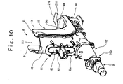
- Such a treating body 56 is formed in a substantially L-shape by a urination and defecation container 82, serving as a lateral casing, of which the inside is formed in a boat shape, and a washing nozzle retainer 61, serving as a vertical casing, which stands upright at the downstream end section of the urination and defecation container 82.
- a front end nozzle bracket 60 is provided at the front end of the urination and defecation container 82.
- the front end nozzle bracket 60 is provided with an injection nozzle 105 for emitting a jet of water to wash away the urine and the stools remaining in the urination and defecation container 82 in the downstream direction.
- Adjacently provided near the injection nozzle 105 is an air supply nozzle 205 for drying the lower surface of the buttocks and the lumbar part of the patient.
- the dead end of the urination and defecation container 82 on the downstream side is provided with a discharge port 102a adapted to discharge urine and stools remaining in the urination and defecation container 82 to an external storage tank 300 through a discharge pipe 103.
- the washing nozzle retainer 61 is provided with a washing nozzle 203, a bidet nozzle 202 and a drying nozzle 204 which are designed to send water or air toward the private parts or anus of the patient.
- a pipe rear anchor leading to each nozzle protrudes from the reverse side of the washing nozzle retainer 61 and communicates with a required branch pipe 62a of a distributor 62 attached to the reverse side of the washing nozzle retainer 61.
- a heater section 63 is mounted on the upper surface of the washing nozzle retainer 61 serving as the vertical casing of the treating body 56, wherein an air pipe in communication with the distributor 62 is heated through the heater section 63.
- the heater section 63 is provided with a suction port 63a and an injection port 63b (refer to Fig. 8 ). Air sent from the suction port 63a is heated by the air pipe and sent as warm air through the injection port 63b.
- the suction port 63a of the heater section 63 is communicatively connected to a drying nozzle pipe 608 adapted to ventilate air sent from a suction pump 400, while the injection port 63b of the heater section 63 is communicatively connected to an air supply opening 62a on the obverse side of the distributor 62. In this manner, air sent from the suction pump 400 is heated and provided to the private parts of the human body from the drying nozzle 204 as a comfortable warm current of air for drying.
- the treating body 56 is formed in a substantially L-shape viewed as a whole by the urination and defecation container 82 formed in a boat shape and the washing nozzle retainer 61 provided upright on the downstream side of the urination and defecation container 82.
- an opening section 83 of the treating body 56 and a nozzle projecting side of the washing nozzle retainer 61 are formed to face each other, an opening edge 84 of the treating body 56 and a side edge of the washing nozzle retainer 61 provide an uninterrupted side edge section 85 of a substantially L-shape as seen from the side.
- the right and left side edge sections 85, 85 are caused to integrally continue inclusive of a front edge section 86 of the urination and defecation container 82 to have a combined L and U-shape, which serves as a body contacting edge section.
- a front edge section 86 of the urination and defecation container 82 In a condition in which the patient holds the urination and defecation treating unit 51 in the crotch of his legs, the crotch of the legs and the buttocks are brought into close contact with the body contacting edge section to keep the inside of the urination and defecation container 82 and the washing nozzle retainer 61 in a highly airtight condition.
- the body contacting edge section is covered by an edge cover 64 which combines the L-shape with the U-shape to cover its edge section.
- the edge cover 64 is provided to form the continuous lower end surface of the edge section in a depressed shape and is made of synthetic resin to be fitted into the body contacting edge section.
- the surface of the edge cover 64 is covered by urethane coated with body-friendly resin.
- Reference numeral 210 is a tongue piece extended from the front end of the edge cover 64. When the edge cover 64 is fitted into the body contacting edge section, the tongue piece 210 is situated to overlap the butt-pad 41 disposed on its periphery. With this provision, it is considered that the patient does not have improper stimulus and an uncomfortable feeling at his buttocks.
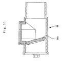
- a hollow one-way valve casing 66 of an octagonal shape in cross-section is installed between the discharge port 102a of the urination and defecation container 82 and the rear anchor side of the discharge pipe 103 to prevent the excretory substance and a foul odor from flowing back.
- the one-way valve casing 66 is vertically provided with a backflow prevention valve 66a (refer to Fig. 11 ), of which the upper end is pivotally supported at the ceiling surface of the one-way valve casing 66, to be openable and closable.
- the backflow prevention valve 66a is always biased in the valve-closing direction by its own weight.
- the excretory substance such as urine and stools goes into circulation more smoothly with circulating force against the valve's bias by its own weight, while the foul odor from the storage tank 300 and the discharge pipe 103 is prevented from inflowing by the valve closure.
- a substantially central section of a bottom surface of the support casing 55 is projectingly provided with an engaging hook 67 of a chevron shape in cross section.
- the downstream section of a bottom surface within the guide passage 34 of the U-shaped casing 55 into which the support casing 55 is fitted is provided with multistage engaging grooves 68 (refer to Fig. 5 ) of a chevron shape in cross section.
- the engaging hook 67 of the urination and defecation treating unit 51 is disengaged from the engaging grooves 68.
- the urination and defecation treating unit 51 can be readily removed from the patient.
- a substantially Z-shaped leaf spring 71 for pushing up the bottom surface of the urination and defecation treating unit 51 on the upstream side and a substantially semi-circular push-up backing plate 72 mounted on the upper surface of the leaf spring 71.
- the push-up backing plate 72 is provided on a flat section of the upper surface of the leaf spring 71, and the downstream edge section of the push-up backing plate 72 is pivotally attached to the guide passage 34. With this arrangement, the push-up backing plate 72 is biased upwards by the leaf spring 71 with a central focus on the pivotally attached section.
- the urination and defecation treating unit 51 is lifted from the guide passage 31 through the support casing 55 and is pushed against the femoral region of the patient for close contact. Further, the upstream side of the urination and defecation treating unit 51 can be always declined from the upstream side to the downstream side by the push-up backing plate 72. This is effective in capably collecting the excretory substance and the wash water within the urination and defecation container 82 into the discharge port 102a.
- the urination and defecation treating unit 51 is provided in various places with a buttocks nozzle 104, an injection nozzle 105, a bidet nozzle 202, and a washing nozzle 203 which are adapted to emit a jet of wash water to wash each region of the human body, and a drying nozzle 204 and an air supply nozzle 205 which are adapted to inject air to dry the private parts and external buttocks of the human body after washing.
- the urination and defection treating unit 51 is also provided in various places with a fitting sensor I, a stool sensor G, a urine sensor H, and a water level sensor J for detecting that the femoral region of the human body has contacted the urination and defecation treating unit 51 and for detecting waste material such as stools discharged within a discharge passage 81 to detect that defecation has been performed, and for conducting, through subsequent electric control, various control operations, for example, operations such as emission of wash water from various nozzles such as the buttocks nozzle 104, the injection nozzle 105, the bidet nozzle 202, and the washing nozzle 203 and discharge of the waste material.
- various control operations for example, operations such as emission of wash water from various nozzles such as the buttocks nozzle 104, the injection nozzle 105, the bidet nozzle 202, and the washing nozzle 203 and discharge of the waste material.
- the urination and defecation treating unit 51 has the treating body 56 provided with various nozzles such as the buttocks nozzle 104, the injection nozzle 105, the bidet nozzle 202, and the washing nozzle 203, and various sensors such as the fitting sensor I, the stool sensor G, the urine sensor H, and the water level sensor J.
- various nozzles such as the buttocks nozzle 104, the injection nozzle 105, the bidet nozzle 202, and the washing nozzle 203 and various sensors such as the fitting sensor I, the stool sensor G, the urine sensor H, and the water level sensor J are designed to be exposed within the urination and defecation treating unit 51.
- Various sensors such as the fitting sensor I, the stool sensor G, the urine sensor H, and the water level sensor J will be described hereunder.
- the urination and defecation treating unit 51 is provided with the washing nozzle 203 disposed at the lower end section of the bottom surface of a front surface depressed section 113 and the bidet nozzle 202 disposed in a position of the bottom surface of the front surface depressed section 113 higher than the washing nozzle 203.
- the urination and defecation treating unit 51 is also provided with the injection nozzle 105 disposed at an end section of the discharge passage 81 on the opposite side of the discharge section 102, and the buttocks nozzle 104 disposed in a higher position than the injection nozzle 105 at the end section of the discharge passage 81 on the opposite side of the discharge section 102.
- the washing nozzle 203 disposed at the lower end section of the bottom surface of a front surface depressed section 113
- the bidet nozzle 202 disposed in a position of the bottom surface of the front surface depressed section 113 higher than the washing nozzle 203.
- wash water is respectively supplied from a processing operating section C to various nozzles such as the buttocks nozzle 104, the injection nozzle 105, the bidet nozzle 202, and the washing nozzle 203 through each nozzle pipe of the buttocks nozzle pipe 602c, the injection nozzle pipe 605, the bidet nozzle pipe 602b, and the washing nozzle pipe 603.
- an external hose 73 (refer to Fig. 8 ).
- One end of the external hose 73 is communicatively connected to the end section of the discharge section 102 of the urination and defecation treating unit 51, while the other end thereof is communicatively connected to the storage tank 300.
- Such an external hose 73 is provided to protect various pipes inserted therein from the impact and pressure applied from outside to maintain the shape and function of each pipe.
- the buttocks nozzle 104 is a nozzle for washing the excretory substance adhered to the buttocks of the patient using wash water.
- the buttocks nozzle 104 is provided with a plurality of injection ports 104a of which the injection direction is directed toward the buttocks of the patient.
- the injection ports 104a are disposed in such a manner that each port has a predetermined curvature to correspond to the curved surface of the buttocks.
- the buttocks nozzle 104 is communicatively connected to the bidet nozzle 202 through a three-way valve 74. Both nozzles 104 and 202 are designed to be capable of simultaneously injecting wash water from the three-way valve 74.
- the injection nozzle 105 is a nozzle for performing the treatment of washing away the stools from the discharge passage 81 to the discharge port 102a, while crushing the stools to pieces by the injection water pressure of the wash water (hereinafter referred to as "stool crushing treatment").
- the injection nozzle 105 is disposed on a protruding section 60a which protrudes from the inner surface of the front end nozzle bracket 60 while gently curving substantially upwards as seen from the front.
- the protruding section 60a is consecutively installed on the front end bottom surface side of the discharge passage 81 lower than the buttocks nozzle 104.
- the injection nozzle 105 has a plurality of stool crushing injection ports 105a of which the injection direction is directed to the bottom surface of the discharge passage 81 and to the area just below the anus of the human body where the stools are tend to most accumulate.
- the stool crushing injection ports 105a are provided so that the spray angle is, for example, in the range of 2 to 10 degrees and wash water is injected toward the center of the discharge passage 81 where the stools tend to most accumulate. With this arrangement, the stools accumulated in the center of the discharge passage 81 are first crushed to secure a flow channel through which the wash water flows toward the discharge section 102.
- the injection nozzle 105 is in communication with a pressure pump 600 and is designed to inject warm water from a hot water tank 501 through the injection nozzle 105 as wash water at high water pressure.
- the bidet nozzle 202 shown in Figs. 9 and 12 is a nozzle for washing the excretory substance adhering to the private parts of the human body and for washing the urine adhering to the inner periphery of the vertical member of the treating body.
- the bidet nozzle 202 is formed in a narrow and long protruding shape so that the private parts can be washed irrespective of sex and difference of body type.
- the bidet nozzle 202 is provided with a plurality of bidet injection ports 202a which are drilled in line and at regular intervals and of which the injection direction is directed to the private parts of the patient.
- the bidet nozzle 202 is also provided with a plurality of urine injection ports 202b which are drilled at regular intervals on the periphery of a protruding shape so that the injection direction is directed to the inner peripheral surface of the vertical member of the treating body.
- the bidet injection ports 202a are drilled in a lattice shape in 9 lines and in 3 rows.
- the bidet nozzle 202 is communicatively connected to the buttock nozzle 104 through the three-way valve 74 and both nozzles 104 and 202 are designed to be capable of simultaneously injecting the wash water from the three-way valve 74.
- the urine injection ports 202b of the bidet nozzle 202 are also provided to wash the urine scattered inside the urination and defecation treating unit 51 at the same time.
- the washing nozzle 203 is a nozzle for washing the excretory substance adhering to the anus and an area around the anus of the patient and is formed in a long, narrow shape to be able to wash the anus and the area around the anus irrespective of the difference of body type by sex.
- the washing nozzle 203 is provided at a lower position than the bidet nozzle 202 and is provided with a plurality of anus injection ports 203a which are drilled at regular intervals and of which the injection direction is directed to the anus and an area around the anus of the patient. For example, as shown in Fig.
- each anus injection port 203a is drilled in substantially 4 lines and 3 rows, wherein the upper port in the center row is formed to be higher than the upper ports in the lateral row.
- the distance between the washing nozzles 203 in the same row is formed to be narrower than the distance between the bidet nozzles 202 in the same row.
- the stool crushing injection port 105a and the anus injection port 203a can be formed to have an orifice structure.
- the injection scope of the wash water can be expanded and as a result, it is possible to wash a wide range of human bodies while controlling the volume of the wash water injected through each injection port of 105a and 203a.
- Wash water is supplied to the bidet nozzle 202, the washing nozzle 203, the injection nozzle 105, and the buttock nozzle 104 from the processing operating section C through various nozzle pipes such as the buttock nozzle pipe 602c, the injection nozzle pipe 605, the bidet nozzle pipe 602b, and the washing nozzle pipe 603. After washing each region of the patient by the wash water, warm air and air blasting are provided to each region through the drying nozzle 204 and the air supply nozzle 205 described later for drying.
- the drying nozzle 204 is a nozzle for drying the private parts, the anus and an area around the anus of the patient, and is provided in the substantially four corners of the bidet nozzle 202 of a long, narrow shape so that the private parts, the anus, and the area around the anus of the patient can be dried by warm air irrespective of the difference of body type by sex.
- the drying nozzle 204 is situated further to the outer side than the bidet nozzle 202 and is integrally formed with the bidet nozzle 202.
- the drying nozzle 204 is also provided with four drying injection ports 204a which are drilled at regular intervals of which the injection direction is directed to the private parts, the anus, and an area around the anus of the patient.
- the drying nozzle 204 is provided in such a manner that, to enable the injection of warm air, air supplied from a suction pump and supplied from the drying nozzle pipe 608 through a solenoid valve 97 (refer to Fig. 1 ) is heated by a heater of a heater section 63 to discharge warm air through the drying injection port 204a.
- two drying injection ports 204a, 204a drilled on the upstream side are provided to inject warm air to the private parts, the anus, and an area around the anus of the human body, while two drying injection ports 204a, 204a drilled on the downstream side are adapted to inject warm air to the anus, an area around the anus, and the buttocks on the upstream side.
- two drying injection ports 204a, 204a drilled on the downstream side are adapted to inject warm air to the anus, an area around the anus, and the buttocks on the upstream side.
- the air supply nozzle 205 is a nozzle for drying an area around the buttocks of the patient.
- the air supply nozzle 205 is provided outside a head section of the front end nozzle bracket 60 and has an upward port to be capable of drying an area around the buttocks and a lumbar region of the patient irrespective of the difference of body type by sex.
- the air supply nozzle 205 is provided to cause an air supply injection port 205a to direct upward so that the injection direction is directed to the area around the buttocks of the patient.
- the air supply nozzle 205 is provided to inject, from an air supply injection port 205a, air which is supplied from a suction pump to enable the injection of air and supplied from an air supply nozzle pipe 609 through a solenoid valve 98 (refer to Fig. 1 ).
- air supplied from the air supply injection port 205a is sprayed onto the area around the buttocks through an opening 211 formed on the tongue piece 210 (refer to Fig. 8 ) to dry, in particular, the buttocks and an area around the lumber region protruding outside the urination and defecation container 82.
- reference alphabet I is a fitting sensor provided on the internal surface of the edge cover 64.
- Reference alphabet G is a stool sensor for detecting stools in the discharge passage 81 and is composed of a light-emitting section 106 and a light-receiving section 107.
- H is a urine sensor for detecting the urine and is provided at the bottom surface of the urination and defecation container 82 on the downstream side.
- J is a .water level sensor for detecting a water level within the urination and defecation container 82 (refer to Figs. 8 and 9 ).
- Reference numeral 120 in a figure is an electrode terminal for the fitting sensor I.
- Reference numeral 109 is an electrode pin for the urine sensor H.
- the urine sensor H is designed to detect the current value in the case where a gentle current is applied between the electrode pins 109, 109 using the wash water or the urine as an electric conductor.
- the urination and defecation treating unit 51 detects the stools and the urine by the stool sensor G and the urine sensor H and the detected signal is sent to the processing operating section C (refer to Fig. 1 ).
- the processing operating section C which has received such a detected signal provides the bidet nozzle pipe 602b, the washing nozzle pipe 603, the injection nozzle pipe 605, and the buttocks nozzle pipe 602c with wash water.
- the wash water is then injected into the urination and defecation treating unit 51 from each nozzle of the bidet nozzle 202, the washing nozzle 203, the injection nozzle 105, and the buttocks nozzle 104.
- Such a water level sensor J is designed to be capable of detecting that the wash water is building up within the urination and defecation container 82 in excess of a predetermined water level.
- the processing operating section C is provided outside the urination and defecation treating unit 51 to carry out various functions for treating urination and defecation.
- the processing operating section C is composed of an excretory substance housing section D for housing human waste discharged from the urination and defecation treating unit 51, a nozzle operating section F for receiving, from the urination and defecation treating unit 51, a fitting signal which shows a close contact condition between the crotch of the patient's legs and the urination and defecation treating unit 51 at a constant pressure, a detection signal of defecation and/or urination, and a water level signal showing the water level rising in the urination and defecation container, and for performing consequent various operation such as a washing operation, and a wash water supply section E for supplying the urination and defecation treating unit 51 with wash water.
- the excretory substance housing section D has a storage tank 300.
- the storage tank 300 is connected to the discharge port 102a of the urination and defecation treating unit 51 through the discharge pipe 103.
- a suction pipe 401a is connected to a hose connecting section 303 adjacent to the discharge pipe 103.
- the storage tank 300 is connected to the nozzle operating section F through the suction pipe 401a.
- the wash water supply section E comprises, as shown in Fig. 1 , a raw water tank 500 for supplying raw water serving as the wash water, a hot water tank 501 for heating the wash water supplied into the urination and defecation treating unit 51 to a predetermined temperature, and a solenoid valve 503 for controlling water supply from the raw water tank 500 to the hot water tank 501.
- Reference numeral 502 is a pipe heater for heating the raw water supplied from the raw water tank 500 through the solenoid valve 503
- reference numeral 505 is a water level sensor for detecting water level
- reference numeral 506 is a temperature sensor for detecting the temperature of the raw water within the hot water tank 501.
- the wash water supply section E in the case where a washing process for supplying the urination and defecation treating unit 51 with warm water in the hot water tank 501 as the wash water is executed, as the wash water of a desired temperature is always supplied to the patient, the patient can get a favorable use condition.
- An outlet provided on the bottom side surface of the hot water tank 501 is connected to the nozzle operating section F through the water supply pipe 504a.
- the wash water heated within the hot water tank 501 is supplied to the nozzle operating section F through the water supply pipe 504a.
- the nozzle operating section F is connected, as described above, to the excretory substance housing section D through the suction pipe 401a and is connected to the wash water supply section E through the water supply pipe 504a.
- reference numeral 401a is a suction pipe
- reference numeral 409 is a suction valve
- 408 is a vacuum tank as a pressure reducing section
- 401b is a suction pipe
- 407a is a bad odor eliminating filter
- 413 is a pressure switch
- 401c is a suction pipe, a NO port of a solenoid valve 96 and a COM port of the solenoid valve 96
- 401d is a suction pipe
- 400 is a suction pump
- 402 is a suction port.
- reference numeral 405 is a discharge port for the suction pump 400, a COM port of a solenoid valve 95 and a NO port of the solenoid valve 95.
- 414 is an air discharge pipe
- 407b is a silencer
- 601b is an air supply pipe
- 606 and 609 are various nozzle pipes
- 204 and 205 are a drying nozzle and an air supply nozzle within a urination and defecation treating unit 51
- 404 is a silencer
- 415 is an external air supply pipe
- 96 is a NC port of a solenoid valve
- 96 is a COM port of a solenoid valve.
- 91, 92 and 39 are various solenoid valves for water supply
- 97 and 98 are various solenoid valves for air supply
- 606 is a solenoid valve unit forming a pipe line with one inlet and three outlets
- 413 is a pressure switch
- 607 is a filter assembly.
- the silencer becomes an air supply port and an exhaust port.
- the water supply pipe 504a is connected to the buttocks nozzle 104, the injection nozzle 105, the bidet nozzle 202, and the washing nozzle 203 within the urination and defecation treating unit 51 through a filter 507, a water supply pipe 504b, a pressure pump 600, a nozzle pipe 601a, various solenoid valves such as 91, 92, 93, a three-way valve 74, and various nozzle pipes such as 602a, 602b, 602c, 603, and 605.
- a vacuum pump 408 for increasing the suction force of the suction pump 400 is disposed between the suction pump 400 and the storage tank 300.
- the urination and defecation process will be described.
- the usage of urination and defecation treating unit 51 will also be described below.
- a diaper 21 is put on a depressed section 12 of a mattress 11.
- the toilet unit A for use in a supine position is fitted into the mattress 11 according to the fitting procedure of the diaper 21 described in (i)
- the crotch of legs and private parts of the patient are covered.
- the patient is in a condition in which he holds a washing nozzle retainer 61 serving as a vertical casing 53 of the toilet unit A for use in a supine position in the crotch of his legs, wherein the patient's buttocks are mounted on a butt-pad 41 and his private parts are facing the urination and defecation container 82 serving as a lateral casing 52.
- the patient urinates and defecates within the urination and defecation container 82 and then, the following urination and defecation treatment is carried out.
- the automatic treating device K for urination and defecation As a treating pattern of the automatic treating device K for urination and defecation, there is an automatic defecation treating mode for automatically conducting each washing process by distinguishing the stools and urine based on the detection of the stool sensor G and the urine sensor H.
- the automatic defecation treating mode there are a stool washing process, a urine washing process, and a drying process, and each process will be described in order.
- the automatic treating device K for urination and defecation is provided with a control section for controlling various nozzles, each sensor, various valves, each pump and the like.
- the control section sends signals to various nozzles, various valves, each pump and the like based on the signal of each sensor to execute various functions.
- the automatic treating device K for urination and defecation executes a drying process for drying a human body and the inside of the urination and defecation treating unit 51.
- various solenoid valves 91 through 93, the NC ports of the solenoid valves 95, 96, the suction valve 409, and the one-way valve 411 are closed. Also, in the initial condition, the NO ports of the solenoid valves 95, 96 are opened.
- the suction valve 409 is opened to activate the suction pump 400. With this operation, bad odor due to the stools within the urination and defecation treating unit 51 and part of the stools are sucked into the storage tank 300.
- air containing the bad odor within the urination and defecation treating unit 51 flows toward the one-way valve casing 66, the discharge pipe 103, the storage tank 300, and the suction pump 400, wherein the bad odor is eliminated through a bad odor eliminating filter 407a before the suction port 402 and the silencer 407b after the exhaust port 405 before being emitted outside.
- a bad odor eliminating filter 407a before the suction port 402 and the silencer 407b after the exhaust port 405 before being emitted outside.
- the sound can be muffled with a provision of the silencer 407b. Since two units of the bad odor eliminating filters 407a, 407a are provided, it is possible to maintain the bad odor eliminating effects for a long time.
- the pressure pump 600 is actuated for a certain period of time.
- the warm water within the hot water tank 501 is sent to the injection nozzle pipe 605 and is injected from the injection nozzle 105 as wash water to execute the stool crushing operation.
- the stools crushed by the stool crushing operation are pushed away in the direction of the discharge passage 81 and are mixed well with the wash water in a waste storage space S by a turbulence phenomenon (hereinafter referred to as "mixing operation due to turbulence phenomenon").
- the water level sensor J detects whether or not the water level within the urination and defecation container 82 is above a certain level.
- the water level sensor J forcibly stops the injection from the injection nozzle 105, wherein the waste substance within the urination and defecation container 82 is sucked and stored in the storage tank 300 through the discharge pipe 103.
- the suction valve 409 is closed to initiate vacuum forming.
- the maximum vacuum pressure e.g. 600 mmHg
- a pressure pump 600 is activated through a control device (not shown) based on the detection signal from the pressure switch 413 to open the suction valve 409.
- the maximum vacuum pressure formed in the vacuum tank 408 the flow of wash water containing the stools is interrupted in the urination and defecation container 82 to cause the turbulent phenomenon whereby the wash water containing the stools is whirled round vertically to produce a swirling flow.
- the pressure pump 600 is stopped and it is judged again whether or not residual stools exist within the discharge passage 81 based on the detected value of the stools sensor G.
- the treating procedure returns to repeat the mixing operation due to the turbulence phenomenon and the vacuum suction operation.
- the mixing operation due to the turbulence phenomenon and the vacuum suction operation are repeated until the stool sensor G no longer detects stools.
- the solenoid valve 93 When residual stools are no longer detected within the discharge passage 81, the solenoid valve 93 is closed. Next, the solenoid valve 91 is opened to activate the pressure pump 600 for a certain period of time. With this, warm water from the hot water tank 501 is sent to the pipe 602a, wherein the warm water is then sent to the bidet nozzle pipe 602b and the buttocks nozzle pipe 602c by the three-way valve 74. On the one hand, the warm water sent to the bidet nozzle pipe 602b is injected from the bidet nozzle 202 as wash water to wash the stools adhering to an area near the private parts of the patient (hereinafter referred to as "bidet washing operation").
- the warm water sent to the buttocks nozzle pipe 602c is injected from the buttocks nozzle 104 as wash water to wash away the stools adhering to an area near the buttocks of the patient (hereinafter referred to as "buttocks washing operation").
- buttocks washing operation it is possible to reduce the washing time since the bidet washing and the buttocks washing can be executed at the same time.
- the solenoid valve 91 is closed.
- the solenoid valve 92 is opened to activate the pressure pump 600 for a certain period of time.
- the warm water from the hot water tank 501 is sent to the washing nozzle pipe 603, wherein the warm water is injected from the washing nozzle 203 as wash water to wash away the stools adhering to an area near the anus of the patient (hereinafter referred to as "anus washing operation").
- the solenoid valve 92 is closed and the buttocks washing operation and the anus washing operation are repeated until the number of washings reaches two times. With this, it is possible to perfectly execute washing of the buttocks and an area near the anus of the patient.
- the operation of the suction pump 400 is stopped to close the suction valve 409, thereby completing the stool washing process.
- the water level sensor J In the stools washing process, when the wash water is injected from the various nozzles, the water level sensor J always detects whether or not the water level within the urination and defecation container 82 is above a certain level. If the water level is above a certain level, the water level sensor J forcibly stops the injection of wash water from the various nozzles to cause the waste material within the urination and defecation container 82 to be forcibly sucked and stored in the storage tank 300 through the discharge pipe 103.
- the suction valve 409 is opened to activate the suction pump 400.
- the solenoid valve 91 is opened, the pressure pump 600 is activated for a certain period of time. With this, the urine is sucked into the storage tank 300 and simultaneously, the buttocks washing operation and the bidet washing operation are executed.
- the solenoid valve 91 is closed to open the solenoid valve 93.
- the suction pump 400 is activated. With this, the vacuum forming within the vacuum tank 408 is initiated.
- the pressure pump 600 is activated and the warm water sent from the hot water tank 501 of the raw water tank 500 is injected as wash water from the injection nozzle 105 through the injection nozzle pipe 605 to push away the urine toward the discharge passage 81.
- the suction valve 409 is opened. At this moment, the urine is sucked and stored into the storage tank 300 at a stretch through the discharge port 102a, the one-way valve casing 66, and the discharge pipe 103 by the maximum vacuum pressure formed in the vacuum tank 408.
- the pressure pump 600 is stopped to stop the suction pump 400.
- the suction valve 409 is closed to complete the urine washing process.
- the bad odor released from the waste material sucked and housed into the storage tank 300 through the one-way valve casing 66, the bad odor eliminating filter 407a, and the silencer 407b is discharged outside the suction pump 400 as little as possible.
- the suction valve 409 is closed.
- the suction pump 400 is activated for a certain period of time. Air introduced from the silencer 404 is heated at the heater section 63 through the air supply pipe 601b, the solenoid valve 97, and the drying nozzle pipe 608 and is sent as dry, warm air through the drying nozzle 204, thereby drying the private parts and buttocks of the human body and the inside of the urination and defecation treating unit 51 with the dry air.
- the solenoid valve 97 and the NC ports of the solenoid valves 95, 96 are closed.
- the suction pump 400 After opening the solenoid valve 98, and the NC ports of the solenoid valves 95, 96, the suction pump 400 is activated for a certain period of time.
- the air introduced from the silencer 404 is sent as dry air blasting from the air supply nozzle 205 via the air supply pipe 601b, the solenoid valve 98, and the air supply nozzle pipe 609, thereby drying the buttocks and the lumbar part of the human body with the dry air.
- the solenoid valve 98 and the NC ports of the solenoid valves 95, 96 are closed to complete the drying process.
- a treating body is housed in a substantially oblong support casing which is formed in a substantially boat shape.
- the treating body is formed in a substantially T-shape by a urination and defecation container, serving as a lateral casing, of which the inside is formed in a boat shape, and a washing nozzle retainer, serving as a vertical casing, which stands upright on the downstream side of the urination and defecation container.
- a head of the urination and defecation container is provided with an injection nozzle for crushing stools of a patient, while the washing nozzle retainer is provided with a washing nozzle and a bidet nozzle.
- the excretory substance can be crushed and washed away by the wash water from the injection nozzle. Since the washing nozzle and the bidet nozzle are unitized, an assembling operation can be made easier.
- a domed cover body for covering the private parts of the patient is pivotally provided to be openable and closable at the upper edge of the washing nozzle retainer.
- the treating body when the treating body is fitted on the patient, the crotch of the legs of the patient in a supine position is first brought into close contact with the vertical member of the urination and defecation container and then the cover body is closed. In this manner, fitting can be made easier and the private parts of the patient can also be covered (hidden) from view. Since the treating body is separated from the support casing, maintenance such as cleaning can be made easier.
- the head section of the urination and defecation container serving as the lateral casing is provided with an air supply nozzle and air can be supplied after washing from a drying nozzle provided on the washing nozzle retainer serving as the vertical casing.
- air supply nozzle provided on the washing nozzle retainer serving as the vertical casing.
- an opening edge of the latter half section of the support casing is detachably provided with a vertical member to cover the back surface of the washing nozzle retainer, the front edge of the vertical member and an opening edge of the first half section of the support casing provide an uninterrupted side edge section of a substantially L-shape as seen from the side, and the side edge section is covered by an edge cover for a comfortable close contact with the crotch of the legs and buttocks of the patient.
- a heater section is provided on the reverse side of the washing nozzle retainer to be communicatively connected to a drying nozzle and the supplied air is heated by the heater section to inject warm air from the drying nozzle. In this manner, it is possible to dry the private parts and buttocks of the patient and the inside of the treating body with warm air from the drying nozzle and to shorten a drying time.
- a one-way valve casing is installed between a discharge port of the urination and defecation container and a discharge pipe to prevent the urination and defecation and a bad odor from flowing back
- the one-way valve casing is vertically provided with a backflow prevention valve, which is pivotally supported at the ceiling surface of the one-way valve casing, to be openable and closable.
Abstract
Description
- The present invention relates to a toilet unit for use in supine position whereby a bed-ridden patient and/or an aged person can treat his urination and defecation in a supine position without someone else's assistance.
- Various diapers and equipment have been devised in the prior art whereby bed-ridden patients and/or aged people can urinate and defecate and treat the urination and defecation in a supine position without any assistance from others. For examples, Patent Document 1 discloses a technique in which a urination and defecation treating body of a substantially L-shape as seen from the side is provided with a stool detection sensor and various nozzles.
- Referring to this technique, when the patient urinates and defecates, he mounts his haunch on the urination and defecation treating body while holding tight an upright section of the urination and defecation treating body in the crotch of his legs. After defecation, the stools detection sensor consisting of a proximity sensor detects the stools to automatically cause wash water to spout through various nozzles, thereby washing not only the private parts, but also the inside of the urination and defecation treating body. The stools are then discharged to the outside through a waste suction hose. In this manner, the defecation treatment of the bed-ridden patients can be performed automatically.
- Patent Document 2 discloses an automatic treating device for defecation comprising a diaper-shaped casing of a substantially L-shape with a box type structure which is long in the longitudinal direction, a plurality of sensors for detecting excretory substances, a plurality of nozzles for injecting wash water to the excretory substances to perform predetermined washing, and a diaper frame in which various nozzles are installed. The plurality of nozzles consecutively installed on the diaper-shaped casing comprises an anal nozzle for washing the anal area, a bidet nozzle for washing the private parts, a buttocks nozzle for washing the buttocks area, and a stool nozzle for crushing the urination and defecation and discharging these to the outside. Each nozzle is also provided with a function for drying the buttocks and private parts.
- Patent Document 1: Japanese Unexamined Patent Publication No.
Hei 8-322868 US 5 681 297 ) - Patent Document 2: Japanese Patent Application No.
2006-209168 -
EP- andA-1314 414US-A-5 363514 both disclose a toilet unit for use in a supine position. - It is therefore an object of the present invention to provide a toilet unit for use in a supine position which can store water in the case of water leakage and can be fitted in place with ease.
- In order to attain this object, according to a first aspect of the present invention, a toilet unit for use in a supine position is provided, which includes a treating body comprising a urination and defecation container which serves as a lateral casing, and a washing nozzle retainer comprising a vertical part which serves as a vertical casing, the inside of said urination and defecation container being formed in a boat shape, the urination and defection container having a head section and downstream side, said washing nozzle retainer standing upright on the downstream side of the urination and defecation container, the treating body being formed in a substantially L-shape as seen from the side by the urination and defecation container and the washing nozzle retainer,
wherein said head section of the urination and defecation container is provided with an injection nozzle for crushing stools of a patient, the washing nozzle retainer being provided with a washing nozzle and a bidet nozzle, characterized in that the toilet unit further has: a substantially oblong support casing which is formed in a substantially boat shape, said treating body being housed in said support casing; a vertical member which covers a backside of the vertical part of the treating body is fitted in an opening edge of a latter half section of the support casing; and a domed cover body for covering private parts of a patient, which is pivotally provided to be openable and closable at an upper end of said vertical member whereby the treating body is fully covered by the support casing, the vertical member and the cover body. - According to a second aspect of the present invention, the toilet unit for use in a supine position according to the first aspect is provided, in which the head section of the urination and defecation container serving as the lateral casing is provided with an air supply nozzle and the washing nozzle retainer serving as the vertical casing is provided with a drying nozzle from which air can be supplied after washing.
- According to a third aspect of the present invention, a toilet unit for use in a supine position according to the first aspect or the second aspect is provided, in which an opening edge of the latter half section of the support casing is detachably provided with a vertical member to cover the back surface of the washing nozzle retainer, the front edge of the vertical member and an opening edge of the first half section of the support casing provide an uninterrupted side edge section of a substantially L-shape as seen from the side, and the side edge section is covered by an edge cover for comfortable close contact with the crotch of the legs and buttocks of the patient.
- According to a fourth aspect of the present invention, the toilet unit for use in a supine position according to the second aspect is provided, in which a heater section is provided on the reverse side of the washing nozzle retainer to be communicatively connected to a drying nozzle and is adapted to heat the supplied air, thereby injecting warm air from the drying nozzle.
- According to a fifth aspect of the present invention, the toilet unit for use in a supine position according to any one of the first through fourth aspects is provided, in which a one-way valve casing is installed between a discharge port of the urination and defecation container and a discharge pipe to prevent the urination and defecation and a bad odor from flowing back, and the one-way valve casing is vertically provided with a backflow prevention valve, which is pivotally supported at the ceiling surface of the one-way valve casing, to be openable and closable.
- The above and other objects, features and advantages of the present invention will become more apparent from the following description when taken in conjunction with the accompanying drawings.
-
Fig. 1 is a view showing the structure of an automatic treating device for urination and defecation according to an embodiment of the present invention; -
Fig. 2 is a perspective view of the external appearance of the automatic treating device for urination and defecation; -
Fig. 3 is a perspective view of a mattress; -
Fig. 4 is a perspective view showing a condition in which a diaper has been fitted on the mattress; -
Fig. 5A is a front view of a U-shaped casing andFig. 5B is a cross-sectional view of the U-shaped casing; -
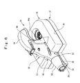
Fig. 6 is a schematic view showing a condition in which a urination and defecation treating unit has been fitted into the U-shaped casing; -
Fig. 7 is a perspective view of the urination and defecation treating unit; -
Fig. 8 is an exploded perspective view of the urination and defecation treating unit; -
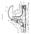
Fig. 9 is a cross-sectional view of the urination and defecation treating unit; -
Fig. 10 is a perspective view of a treating body; -
Fig. 11 is a cross-sectional view of a one-way valve casing; -
Fig. 12 is a front view of various nozzles; and -
Fig. 13A is a perspective view of a front end nozzle bracket,Fig. 13B is a front view the front end nozzle bracket, andFig. 13C is a rear view thereof. - Preferred embodiments of the present invention will now be described with reference to the accompanying drawings.
- As shown in
Fig. 1 , reference alphabet A shows a toilet unit for use in a supine position. A patient in a supine position urinates and defecates in a condition in which he holds the toilet unit A for use in a supine position according to the present invention in the crotch of his legs. The urine and stools are then automatically sent to a storage tank from the toilet unit A for use in a supine position, and the buttocks, private parts and the like of the patient are washed and then dried by an air supply. - As shown in
Fig. 2 , the toilet unit A for use in a supine position is provided in such a manner that adepressed section 12 is formed in the middle of amattress 11, made of urethane, which has such an area that the patient can lie supine. One side of thedepressed section 12 communicates with apipe passage 13 formed on themattress 11. - As shown in
Figs. 2 and4 , thedepressed section 12 is formed in a substantially rectangular shape. Adiaper 21 with anopening 22 in the center corresponding to thedepressed section 12 is put on thedepressed section 12. Thediaper 21 is provided in such a manner that acrotch covering section 23 extended on the downstream side of thediaper 21 and aturnover section 24 extended on the upstream side thereof protrude from the outer periphery of thedepressed section 12 while causing theopening 22 to correspond to thedepressed section 12. - A
U-shaped casing 31 of a substantially rectangular shape described later is fitted into thedepressed section 12. A substantially U-shaped butt-pad 41 made of urethane is mounted on the U-shapedcasing 31. Alateral casing 52 of a substantially L-shape of a urination anddefecation treating unit 51 is loosely fitted into a U-shapedcentral groove section 42 of the butt-pad 41 so that avertical casing 53 of a substantially L-shape of the urination anddefecation treating unit 51 protrudes upwards from the upper surface of the butt-pad 41. - The patient lies supine on the
mattress 11 and mounts his buttocks on the butt-pad 41. As shown inFig. 9 , the patient urinates and defecates on the boat-shaped inside of the substantially L-shapedlateral casing 52 holding the substantially L-shapedvertical casing 53 of the urination anddefecation treating unit 51 in the crotch of his legs. Urine and stools are then discharged out of the urination anddefecation treating unit 51 by the water discharged from aninjection nozzle 105 provided on a head section 52a of thelateral casing 52. The buttocks and private parts of the patient are then washed by the wash water emitted from awashing nozzle 203 and abidet nozzle 202 provided on thevertical casing 53 of the urination anddefecation treating unit 51. The buttocks are also washed by the wash water discharged through a buttocks-nozzle 104 provided on thelateral casing 52 of the urination anddefecation treating unit 51. Subsequently, the buttocks and private parts are dried by the air blasting from a dryingnozzle 204 and anair supply nozzle 205. - As shown in
Figs. 2 and4 , thediaper 21 is provided in the center with theopening 22 corresponding to thedepressed section 12. Extended on the downstream side of theopening 22 is thecrotch covering section 23 for covering the crotch of the patient's legs, while extended on the upstream side of theopening 22 is the laterally projectingturnover section 24. - The
diaper 21 is mounted on themattress 11 in a spread-out manner to surround the periphery of thedepressed section 12 of themattress 11. The center of thecrotch covering section 23 of thediaper 21 is provided with a cutting-plane line 25 to be united or detached by a zipper. Another end of the zipper is ended in the middle of thecrotch covering section 23. In this manner, thecrotch covering section 23 can be expanded laterally from the cutting-plane line 25. The urination anddefecation treating unit 51 described later, when fitted, can readily pass through theU-shaped groove section 42 of the substantially U-shaped butt-pad 41 described later, which is fitted into thedepressed section 12 of themattress 11, without causing interference with thediaper 21. - Steps for putting the
diaper 21 on the patient will now be described. - As shown in
Figs. 2 through 4 , thediaper 21 provided in the center with theopening 22 corresponding to thedepressed section 12 is put on thedepressed section 12 of themattress 11 to cause theopening 22 to correspond to thedepressed section 12, wherein thecrotch covering section 23 extended on the downstream side of thediaper 21 and theturnover section 24 extended on the upstream side thereof protrude to the outer periphery of thedepressed section 12. - Now, the
U-shaped casing 31 is fitted into theopening 22 of thediaper 21 and the butt-pad 41 is mounted on theU-shaped casing 31, wherein a care provider causes the patient's buttocks to mount on the butt-pad 41. Thus, the supine patient is brought in a supine position on themattress 11. - Next, the
diaper 21 is caused to expand laterally from the cutting-plane line 25 to produce an opening. The toilet unit A for use in a supine position to which adischarge pipe 103 is consecutively connected is inserted into the opening expanded laterally to be fitted into theU-shaped groove section 42 of the butt-pad 41. The toilet unit A for use in a supine position is thus held in the crotch of the patient' legs and the private parts of the patient are hidden from view by acover body 59. In this case, the crotch of the legs is brought into close contact withelectrode terminals - Then, the right and left
turnover sections 24 of thediaper 21 are wrapped around an abdominal region of the patient to fold and each tape of theturnover sections 24 is fastened. After covering thecover body 59 with thecrotch covering section 23 of thediaper 21, each tape provided at the dead end section of thecrotch covering section 23 is fastened to theturnover section 24 of the abdominal region to complete the fitting operation of the toilet unit A for use in a supine position. - As shown in
Figs. 2 and5 , theU-shaped casing 31 is formed in a box shape, of which the upper section is open, corresponding to a substantially rectangular shape of thedepressed section 12. In other words, theU-shaped casing 31 has an outer shape which can be loosely fitted into thedepressed section 12. An outerperipheral wall 33 stands upright at the outer peripheral edge of abottom plate 32 at least in a condition lower than the thickness of the butt-pad 41 described later. Further, longitudinally provided in the center of thebottom plate 32 is a band-shapedguide passage 34. Aguide wall 35 is provided on both sides of theguide passage 34. - The
guide passage 34 protrudes outside the outerperipheral wall 33 on the downstream side to project from the dead end of thebottom plate 32 on the downstream side, thereby making the dead end of a protrudingsection 36 open. Accordingly, when theU-shaped casing 31 is fitted into thedepressed section 12 of themattress 11, the protrudingsection 36 of theguide passage 34 is caused to be inserted in apipe passage 13 which communicates with thedepressed section 12. - In such a
U-shaped casing 31 constructed above, aU-shaped space 37 is provided between the outerperipheral wall 33 and the band-shapedguide passage 34. The substantially U-shaped butt-pad 41 described later is fitted and held into theU-shaped space 37. - As shown in
Figs. 2 and6 , the butt-pad 41 is also formed in a substantially U-shape to be fitted into theU-shaped space 37 of a substantially U-shape formed on theU-shaped casing 31 and is provided in such a manner that theguide wall 35 of theguide passage 34 of theU-shaped casing 31 can be fitted into the centralU-shaped groove section 42. - Raw material in which flexible material such as urethane is included is used for the butt-
pad 41. It is also desirable that the material be good in mounting stability of the patient's buttocks and have a feel which is friendly to the buttocks' skin surface. In particular, it is necessary for the material to excel not only in water-proofing, water-repellent and water-absorbing properties, but also in a ventilation property which does not hold humidity. It is also necessary for the but-pad 41 to have the material and feel which can prevent bedsores in the patient. - The thickness of the butt-
pad 41 is at least equivalent to that of thedepressed section 12 of themattress 11 and is set higher than the outerperipheral wall 33 of theU-shape casing 31. - In the condition in which the butt-
pad 41 is fitted into theU-shaped space 37 of theU-shaped casing 31, thecentral groove section 42 of the butt-pad 41 is integral with theguide passage 34. - Further, the
U-shaped space 37 described later of theU-shaped casing 31 is effective in storing leakage water and preventing the leakage water from wetting the reverse side of themattress 11 even though the wash water leaking from the inside of the urination anddefecation treating unit 51 infiltrates from the peripheral surface of the butt-pad 41. - As shown in
Figs. 2 and8 , the urination anddefecation treating unit 51 comprises asupport casing 55 of a substantially oblong shape which is fitted into theguide passage 34 of theU-shaped casing 31, that is, the U-shapedcentral groove section 42 of the butt-pad 41, and a substantially L-shaped treatingbody 56 which is fitted into and housed in thesupport casing 55. The treatingbody 56 is designed to have a predetermined rigidity to prevent the urination anddefecation treating unit 51 from being distorted by the patient's weight. - As shown in
Figs. 8 and9 , thesupport casing 55 is provided with a peripheral wall on the periphery and is formed in a boat shape to house the treating body 56 (described later) therein. The right and left side walls of thesupport casing 55 are upraised in a chevron shape in the center. Theseupraised sections 55a and an opening edge of the latter half section of thesupport casing 55 are provided to allow avertical member 57 to be fitted therein. Thevertical member 57 is formed in a semicircular arc shape in cross-section and in a substantially L-shape as seen from the side to cover the backside of avertical part 80 of the substantially L-shape treating body 5fi described later and part of the upper surface of the treatingbody 56. In the figure,reference numeral 55b is an opening edge of the latter half section of thesupport casing support casing vertical member 57. - Connected to an end opening on the downstream side formed by assembly of the
support casing 55 and thevertical member 57 is acylindrical casing 58 into which adischarge passage 81 for urine and stools provided at the downstream end of the treatingbody 56 described later and a discharge pipe 103 (refer toFig. 1 ) in communication with thedischarge passage 81 are inserted. - Further, a
cover body 59 adapted to cover (hide) the private parts of the patient from view is pivotally attached to the upper edge of thevertical member 57 which covers the backside of avertical part 80 of the treatingbody 56. - The
cover body 59 is formed in a dome shape and the rear anchor is pivotally attached to the upper end of thevertical member 57, which is formed in a semicircular arc shape in cross section, through apin 59a. Thecover body 59 is provided to openably and closably cover (hide) the upper part of the private parts of the patient from view in a condition in which the patient holds the treatingbody 56 in the crotch of his legs. - In this manner, the treating
body 56 can be fully covered by thesupport casing 55, thevertical member 57, thecylindrical case 58 and thecover body 59, except for a projected nozzle section adapted to carry out a necessary treating function for urination and defecation. - Such a treating
body 56 is formed in a substantially L-shape by a urination anddefecation container 82, serving as a lateral casing, of which the inside is formed in a boat shape, and awashing nozzle retainer 61, serving as a vertical casing, which stands upright at the downstream end section of the urination anddefecation container 82. - As shown in
Figs. 8 and13 , a frontend nozzle bracket 60 is provided at the front end of the urination anddefecation container 82. The frontend nozzle bracket 60 is provided with aninjection nozzle 105 for emitting a jet of water to wash away the urine and the stools remaining in the urination anddefecation container 82 in the downstream direction. Adjacently provided near theinjection nozzle 105 is anair supply nozzle 205 for drying the lower surface of the buttocks and the lumbar part of the patient. - As shown in
Fig. 9 , the dead end of the urination anddefecation container 82 on the downstream side is provided with adischarge port 102a adapted to discharge urine and stools remaining in the urination anddefecation container 82 to anexternal storage tank 300 through adischarge pipe 103. - As shown in
Figs. 9 and12 , thewashing nozzle retainer 61 is provided with awashing nozzle 203, abidet nozzle 202 and a dryingnozzle 204 which are designed to send water or air toward the private parts or anus of the patient. - As shown in
Figs. 8 though 10, a pipe rear anchor leading to each nozzle protrudes from the reverse side of thewashing nozzle retainer 61 and communicates with a requiredbranch pipe 62a of adistributor 62 attached to the reverse side of thewashing nozzle retainer 61. On the reverse side of thedistributor 62, aheater section 63 is mounted on the upper surface of thewashing nozzle retainer 61 serving as the vertical casing of the treatingbody 56, wherein an air pipe in communication with thedistributor 62 is heated through theheater section 63. - The
heater section 63 is provided with asuction port 63a and aninjection port 63b (refer toFig. 8 ). Air sent from thesuction port 63a is heated by the air pipe and sent as warm air through theinjection port 63b. Thesuction port 63a of theheater section 63 is communicatively connected to a dryingnozzle pipe 608 adapted to ventilate air sent from asuction pump 400, while theinjection port 63b of theheater section 63 is communicatively connected to anair supply opening 62a on the obverse side of thedistributor 62. In this manner, air sent from thesuction pump 400 is heated and provided to the private parts of the human body from the dryingnozzle 204 as a comfortable warm current of air for drying. - As shown in
Figs. 8 through 10 , the treatingbody 56 is formed in a substantially L-shape viewed as a whole by the urination anddefecation container 82 formed in a boat shape and thewashing nozzle retainer 61 provided upright on the downstream side of the urination anddefecation container 82. As anopening section 83 of the treatingbody 56 and a nozzle projecting side of thewashing nozzle retainer 61 are formed to face each other, an openingedge 84 of the treatingbody 56 and a side edge of thewashing nozzle retainer 61 provide an uninterruptedside edge section 85 of a substantially L-shape as seen from the side. - The right and left
side edge sections front edge section 86 of the urination anddefecation container 82 to have a combined L and U-shape, which serves as a body contacting edge section. In a condition in which the patient holds the urination anddefecation treating unit 51 in the crotch of his legs, the crotch of the legs and the buttocks are brought into close contact with the body contacting edge section to keep the inside of the urination anddefecation container 82 and thewashing nozzle retainer 61 in a highly airtight condition. For that purpose, the body contacting edge section is covered by anedge cover 64 which combines the L-shape with the U-shape to cover its edge section. - In other words, the
edge cover 64 is provided to form the continuous lower end surface of the edge section in a depressed shape and is made of synthetic resin to be fitted into the body contacting edge section. The surface of theedge cover 64 is covered by urethane coated with body-friendly resin.Reference numeral 210 is a tongue piece extended from the front end of theedge cover 64. When theedge cover 64 is fitted into the body contacting edge section, thetongue piece 210 is situated to overlap the butt-pad 41 disposed on its periphery. With this provision, it is considered that the patient does not have improper stimulus and an uncomfortable feeling at his buttocks. - As shown in
Figs. 8 and9 , a hollow one-way valve casing 66 of an octagonal shape in cross-section is installed between thedischarge port 102a of the urination anddefecation container 82 and the rear anchor side of thedischarge pipe 103 to prevent the excretory substance and a foul odor from flowing back. The one-way valve casing 66 is vertically provided with abackflow prevention valve 66a (refer toFig. 11 ), of which the upper end is pivotally supported at the ceiling surface of the one-way valve casing 66, to be openable and closable. Thebackflow prevention valve 66a is always biased in the valve-closing direction by its own weight. The excretory substance such as urine and stools goes into circulation more smoothly with circulating force against the valve's bias by its own weight, while the foul odor from thestorage tank 300 and thedischarge pipe 103 is prevented from inflowing by the valve closure. - Further, as shown in
Fig. 9 , a substantially central section of a bottom surface of thesupport casing 55 is projectingly provided with an engaginghook 67 of a chevron shape in cross section. The downstream section of a bottom surface within theguide passage 34 of theU-shaped casing 55 into which thesupport casing 55 is fitted is provided with multistage engaging grooves 68 (refer toFig. 5 ) of a chevron shape in cross section. In the case where thesupport casing 55 is fitted into theguide passage 34 in a sliding manner toward the front direction from behind, by the engagement of the engaginghook 67 with the engaginggrooves 68, it is possible to prevent the treatingbody 56 within the support casing 55 from being inserted too far into the fork (crotch) of the patient's legs and to secure the fitting position of the urination anddefecation treating unit 51 and the femoral region of the patient in the longitudinal direction in an optimum close contact location, and to always improve the degree of contact between the urination anddefecation treating unit 51 and the femoral region of the patient. In the case where the patient has a feeling of oppression when he holds the urination anddefecation treating unit 51 in the crotch of his legs, if the urination anddefecation treating unit 51 is lifted upwards, the engaginghook 67 is disengaged from the engaginggrooves 68. By sliding the treatingbody 56 along theguide passage 34 to fine adjust the engaging position of the engaginghook 67 in the backward position of theguide passage 34, it is possible to cause the engaginghook 67 to engage the engaginggrooves 68 to bring it into an optimum engaging position and as a result, the patient's oppressive feeling can be reduced. In the case where the urination anddefecation treating unit 56 is removed from the patient, by lifting the urination anddefecation treating unit 51 upwards, the engaginghook 67 of the urination anddefecation treating unit 51 is disengaged from the engaginggrooves 68. Thus, the urination anddefecation treating unit 51 can be readily removed from the patient. - Installed between the upstream side within the
guide passage 34 of theU-shaped casing 31 and the bottom surface of thesupport casing 55 on the upstream side are a substantially Z-shapedleaf spring 71 for pushing up the bottom surface of the urination anddefecation treating unit 51 on the upstream side and a substantially semi-circular push-upbacking plate 72 mounted on the upper surface of theleaf spring 71. In other words, the push-upbacking plate 72 is provided on a flat section of the upper surface of theleaf spring 71, and the downstream edge section of the push-upbacking plate 72 is pivotally attached to theguide passage 34. With this arrangement, the push-upbacking plate 72 is biased upwards by theleaf spring 71 with a central focus on the pivotally attached section. By such biasing force of theleaf spring 71, the urination anddefecation treating unit 51 is lifted from theguide passage 31 through thesupport casing 55 and is pushed against the femoral region of the patient for close contact. Further, the upstream side of the urination anddefecation treating unit 51 can be always declined from the upstream side to the downstream side by the push-upbacking plate 72. This is effective in capably collecting the excretory substance and the wash water within the urination anddefecation container 82 into thedischarge port 102a. - As shown in
Figs. 1 and9 , the urination anddefecation treating unit 51 is provided in various places with abuttocks nozzle 104, aninjection nozzle 105, abidet nozzle 202, and awashing nozzle 203 which are adapted to emit a jet of wash water to wash each region of the human body, and a dryingnozzle 204 and anair supply nozzle 205 which are adapted to inject air to dry the private parts and external buttocks of the human body after washing. The urination anddefection treating unit 51 is also provided in various places with a fitting sensor I, a stool sensor G, a urine sensor H, and a water level sensor J for detecting that the femoral region of the human body has contacted the urination anddefecation treating unit 51 and for detecting waste material such as stools discharged within adischarge passage 81 to detect that defecation has been performed, and for conducting, through subsequent electric control, various control operations, for example, operations such as emission of wash water from various nozzles such as thebuttocks nozzle 104, theinjection nozzle 105, thebidet nozzle 202, and thewashing nozzle 203 and discharge of the waste material. - In this manner, the urination and
defecation treating unit 51 has the treatingbody 56 provided with various nozzles such as thebuttocks nozzle 104, theinjection nozzle 105, thebidet nozzle 202, and thewashing nozzle 203, and various sensors such as the fitting sensor I, the stool sensor G, the urine sensor H, and the water level sensor J. Various nozzles such as thebuttocks nozzle 104, theinjection nozzle 105, thebidet nozzle 202, and thewashing nozzle 203 and various sensors such as the fitting sensor I, the stool sensor G, the urine sensor H, and the water level sensor J are designed to be exposed within the urination anddefecation treating unit 51. Various sensors such as the fitting sensor I, the stool sensor G, the urine sensor H, and the water level sensor J will be described hereunder. - As shown in
Figs. 9 and12 , the urination anddefecation treating unit 51 is provided with thewashing nozzle 203 disposed at the lower end section of the bottom surface of a front surfacedepressed section 113 and thebidet nozzle 202 disposed in a position of the bottom surface of the front surfacedepressed section 113 higher than thewashing nozzle 203. The urination anddefecation treating unit 51 is also provided with theinjection nozzle 105 disposed at an end section of thedischarge passage 81 on the opposite side of thedischarge section 102, and thebuttocks nozzle 104 disposed in a higher position than theinjection nozzle 105 at the end section of thedischarge passage 81 on the opposite side of thedischarge section 102. As shown inFig. 1 , thebuttocks nozzle 104, theinjection nozzle 105, thebidet nozzle 202, and thewashing nozzle 203 are connected to abuttocks nozzle pipe 602c, aninjection nozzle pipe 605, abidet nozzle pipe 602b, and awashing nozzle pipe 603, respectively. Thus, wash water is respectively supplied from a processing operating section C to various nozzles such as thebuttocks nozzle 104, theinjection nozzle 105, thebidet nozzle 202, and thewashing nozzle 203 through each nozzle pipe of thebuttocks nozzle pipe 602c, theinjection nozzle pipe 605, thebidet nozzle pipe 602b, and thewashing nozzle pipe 603. - These various pipes are tied in a bundle to be inserted into an external hose 73 (refer to
Fig. 8 ). One end of theexternal hose 73 is communicatively connected to the end section of thedischarge section 102 of the urination anddefecation treating unit 51, while the other end thereof is communicatively connected to thestorage tank 300. Such anexternal hose 73 is provided to protect various pipes inserted therein from the impact and pressure applied from outside to maintain the shape and function of each pipe. - As shown in
Figs. 9 and13 , thebuttocks nozzle 104 is a nozzle for washing the excretory substance adhered to the buttocks of the patient using wash water. Thebuttocks nozzle 104 is provided with a plurality ofinjection ports 104a of which the injection direction is directed toward the buttocks of the patient. Theinjection ports 104a are disposed in such a manner that each port has a predetermined curvature to correspond to the curved surface of the buttocks. Thebuttocks nozzle 104 is communicatively connected to thebidet nozzle 202 through a three-way valve 74. Bothnozzles way valve 74. - The
injection nozzle 105 is a nozzle for performing the treatment of washing away the stools from thedischarge passage 81 to thedischarge port 102a, while crushing the stools to pieces by the injection water pressure of the wash water (hereinafter referred to as "stool crushing treatment"). Theinjection nozzle 105 is disposed on a protrudingsection 60a which protrudes from the inner surface of the frontend nozzle bracket 60 while gently curving substantially upwards as seen from the front. The protrudingsection 60a is consecutively installed on the front end bottom surface side of thedischarge passage 81 lower than thebuttocks nozzle 104. Theinjection nozzle 105 has a plurality of stool crushinginjection ports 105a of which the injection direction is directed to the bottom surface of thedischarge passage 81 and to the area just below the anus of the human body where the stools are tend to most accumulate. The stool crushinginjection ports 105a are provided so that the spray angle is, for example, in the range of 2 to 10 degrees and wash water is injected toward the center of thedischarge passage 81 where the stools tend to most accumulate. With this arrangement, the stools accumulated in the center of thedischarge passage 81 are first crushed to secure a flow channel through which the wash water flows toward thedischarge section 102. Accordingly, in the early stage in which injection of wash water is initiated from theinjection nozzle 105, it is possible to prevent the condition in which the wash water blocked off by the stools spills out of thedischarge passage 81. Further, theinjection nozzle 105 is in communication with apressure pump 600 and is designed to inject warm water from ahot water tank 501 through theinjection nozzle 105 as wash water at high water pressure. - The
bidet nozzle 202 shown inFigs. 9 and12 is a nozzle for washing the excretory substance adhering to the private parts of the human body and for washing the urine adhering to the inner periphery of the vertical member of the treating body. Thebidet nozzle 202 is formed in a narrow and long protruding shape so that the private parts can be washed irrespective of sex and difference of body type. Thebidet nozzle 202 is provided with a plurality ofbidet injection ports 202a which are drilled in line and at regular intervals and of which the injection direction is directed to the private parts of the patient. Thebidet nozzle 202 is also provided with a plurality ofurine injection ports 202b which are drilled at regular intervals on the periphery of a protruding shape so that the injection direction is directed to the inner peripheral surface of the vertical member of the treating body. For example, as shown inFig. 12 , thebidet injection ports 202a are drilled in a lattice shape in 9 lines and in 3 rows. As described above, thebidet nozzle 202 is communicatively connected to thebuttock nozzle 104 through the three-way valve 74 and bothnozzles way valve 74. With this configuration, by injecting wash water from each lattice-shapedport 202a in a surface condition, a wide range of washing is possible, the injection pressure of the wash water can be controlled to a moderate degree, and soft washing toward the private parts which are most delicate in the human body can be realized. Theurine injection ports 202b of thebidet nozzle 202 are also provided to wash the urine scattered inside the urination anddefecation treating unit 51 at the same time. - As shown in
Figs. 9 and12 , thewashing nozzle 203 is a nozzle for washing the excretory substance adhering to the anus and an area around the anus of the patient and is formed in a long, narrow shape to be able to wash the anus and the area around the anus irrespective of the difference of body type by sex. Thewashing nozzle 203 is provided at a lower position than thebidet nozzle 202 and is provided with a plurality ofanus injection ports 203a which are drilled at regular intervals and of which the injection direction is directed to the anus and an area around the anus of the patient. For example, as shown inFig. 12 , eachanus injection port 203a is drilled in substantially 4 lines and 3 rows, wherein the upper port in the center row is formed to be higher than the upper ports in the lateral row. The distance between thewashing nozzles 203 in the same row is formed to be narrower than the distance between thebidet nozzles 202 in the same row. With this arrangement, it is possible to wash the anus and the area around the anus of the human body irrespective of the difference of body type by sex. Water pressure of the wash water emitted through eachanus injection port 203a is designed to be stronger than that of the wash water injected through thebidet injection ports 202a. - To realize more effective washing, the stool crushing
injection port 105a and theanus injection port 203a can be formed to have an orifice structure. By adopting the orifice structure, the injection scope of the wash water can be expanded and as a result, it is possible to wash a wide range of human bodies while controlling the volume of the wash water injected through each injection port of 105a and 203a. - Wash water is supplied to the
bidet nozzle 202, thewashing nozzle 203, theinjection nozzle 105, and thebuttock nozzle 104 from the processing operating section C through various nozzle pipes such as thebuttock nozzle pipe 602c, theinjection nozzle pipe 605, thebidet nozzle pipe 602b, and thewashing nozzle pipe 603. After washing each region of the patient by the wash water, warm air and air blasting are provided to each region through the dryingnozzle 204 and theair supply nozzle 205 described later for drying. - As shown in
Figs. 9 and12 , the dryingnozzle 204 is a nozzle for drying the private parts, the anus and an area around the anus of the patient, and is provided in the substantially four corners of thebidet nozzle 202 of a long, narrow shape so that the private parts, the anus, and the area around the anus of the patient can be dried by warm air irrespective of the difference of body type by sex. The dryingnozzle 204 is situated further to the outer side than thebidet nozzle 202 and is integrally formed with thebidet nozzle 202. The dryingnozzle 204 is also provided with four dryinginjection ports 204a which are drilled at regular intervals of which the injection direction is directed to the private parts, the anus, and an area around the anus of the patient. The dryingnozzle 204 is provided in such a manner that, to enable the injection of warm air, air supplied from a suction pump and supplied from the dryingnozzle pipe 608 through a solenoid valve 97 (refer toFig. 1 ) is heated by a heater of aheater section 63 to discharge warm air through the dryinginjection port 204a. With this arrangement, it is possible to efficiently dry the private parts, the anus, and an area around the anus of human body with comfortable warm air in a short time irrespective of the difference of body type by sex. For example, two dryinginjection ports injection ports - As shown in
Figs. 9 and13C , theair supply nozzle 205 is a nozzle for drying an area around the buttocks of the patient. Theair supply nozzle 205 is provided outside a head section of the frontend nozzle bracket 60 and has an upward port to be capable of drying an area around the buttocks and a lumbar region of the patient irrespective of the difference of body type by sex. Theair supply nozzle 205 is provided to cause an airsupply injection port 205a to direct upward so that the injection direction is directed to the area around the buttocks of the patient. Theair supply nozzle 205 is provided to inject, from an airsupply injection port 205a, air which is supplied from a suction pump to enable the injection of air and supplied from an airsupply nozzle pipe 609 through a solenoid valve 98 (refer toFig. 1 ). With this arrangement, it is possible to efficiently dry an area around the buttocks of human body in a short time ir respective of the difference of body type by sex. For example, air supplied from the airsupply injection port 205a is sprayed onto the area around the buttocks through anopening 211 formed on the tongue piece 210 (refer toFig. 8 ) to dry, in particular, the buttocks and an area around the lumber region protruding outside the urination anddefecation container 82. - As shown in
Figs. 1 and9 , reference alphabet I is a fitting sensor provided on the internal surface of theedge cover 64. Reference alphabet G is a stool sensor for detecting stools in thedischarge passage 81 and is composed of a light-emittingsection 106 and a light-receivingsection 107. H is a urine sensor for detecting the urine and is provided at the bottom surface of the urination anddefecation container 82 on the downstream side. J is a .water level sensor for detecting a water level within the urination and defecation container 82 (refer toFigs. 8 and9 ).Reference numeral 120 in a figure is an electrode terminal for the fitting sensor I. The fitting position of theelectrode terminals vertical section 64a of theedge cover 64 and near the inner edge section.Reference numeral 109 is an electrode pin for the urine sensor H. The urine sensor H is designed to detect the current value in the case where a gentle current is applied between the electrode pins 109, 109 using the wash water or the urine as an electric conductor. - With such an arrangement, when the patient defecates and/or urinates, the urination and
defecation treating unit 51 detects the stools and the urine by the stool sensor G and the urine sensor H and the detected signal is sent to the processing operating section C (refer toFig. 1 ). The processing operating section C which has received such a detected signal provides thebidet nozzle pipe 602b, thewashing nozzle pipe 603, theinjection nozzle pipe 605, and thebuttocks nozzle pipe 602c with wash water. The wash water is then injected into the urination anddefecation treating unit 51 from each nozzle of thebidet nozzle 202, thewashing nozzle 203, theinjection nozzle 105, and thebuttocks nozzle 104. With this, the buttocks section, private parts and the anus of the patient are washed and the urine and stools are washed away toward thedischarge section 102. After completing such a washing process for washing each region of the patient and the inside of the urination anddefecation treating unit 51, air is sent to the dryingnozzle pipe 608 and the airsupply nozzle pipe 609 and then warm air and air of air blasting are injected into the urination anddefecation treating unit 51 from the dryingnozzle 204 and theair supply nozzle 205. In this manner, a drying process for drying the buttocks section, the private parts and the anus of the patient is executed. - Such a water level sensor J is designed to be capable of detecting that the wash water is building up within the urination and
defecation container 82 in excess of a predetermined water level. - The processing operating section C is provided outside the urination and
defecation treating unit 51 to carry out various functions for treating urination and defecation. As shown inFig. 1 , the processing operating section C is composed of an excretory substance housing section D for housing human waste discharged from the urination anddefecation treating unit 51, a nozzle operating section F for receiving, from the urination anddefecation treating unit 51, a fitting signal which shows a close contact condition between the crotch of the patient's legs and the urination anddefecation treating unit 51 at a constant pressure, a detection signal of defecation and/or urination, and a water level signal showing the water level rising in the urination and defecation container, and for performing consequent various operation such as a washing operation, and a wash water supply section E for supplying the urination anddefecation treating unit 51 with wash water. - As shown in
Fig. 1 , a suction pipe 401a is connected to ahose connecting section 303 adjacent to thedischarge pipe 103. As shown inFig. 1 , thestorage tank 300 is connected to the nozzle operating section F through the suction pipe 401a. - The wash water supply section E comprises, as shown in
Fig. 1 , araw water tank 500 for supplying raw water serving as the wash water, ahot water tank 501 for heating the wash water supplied into the urination anddefecation treating unit 51 to a predetermined temperature, and asolenoid valve 503 for controlling water supply from theraw water tank 500 to thehot water tank 501.Reference numeral 502 is a pipe heater for heating the raw water supplied from theraw water tank 500 through thesolenoid valve 503,reference numeral 505 is a water level sensor for detecting water level, andreference numeral 506 is a temperature sensor for detecting the temperature of the raw water within thehot water tank 501. - In the wash water supply section E, in the case where a washing process for supplying the urination and
defecation treating unit 51 with warm water in thehot water tank 501 as the wash water is executed, as the wash water of a desired temperature is always supplied to the patient, the patient can get a favorable use condition. An outlet provided on the bottom side surface of thehot water tank 501 is connected to the nozzle operating section F through thewater supply pipe 504a. The wash water heated within thehot water tank 501 is supplied to the nozzle operating section F through thewater supply pipe 504a. - The nozzle operating section F is connected, as described above, to the excretory substance housing section D through the suction pipe 401a and is connected to the wash water supply section E through the
water supply pipe 504a. As shown inFig. 1 , reference numeral 401a is a suction pipe,reference numeral 409 is a suction valve, 408 is a vacuum tank as a pressure reducing section, 401b is a suction pipe, 407a is a bad odor eliminating filter, 413 is a pressure switch, 401c is a suction pipe, a NO port of asolenoid valve 96 and a COM port of thesolenoid valve reference numeral 405 is a discharge port for thesuction pump 400, a COM port of asolenoid valve 95 and a NO port of thesolenoid valve 95. 414 is an air discharge pipe, 407b is a silencer, 601b is an air supply pipe, 606 and 609 are various nozzle pipes, 204 and 205 are a drying nozzle and an air supply nozzle within a urination anddefecation treating unit - The
water supply pipe 504a is connected to thebuttocks nozzle 104, theinjection nozzle 105, thebidet nozzle 202, and thewashing nozzle 203 within the urination anddefecation treating unit 51 through afilter 507, awater supply pipe 504b, apressure pump 600, anozzle pipe 601a, various solenoid valves such as 91, 92, 93, a three-way valve 74, and various nozzle pipes such as 602a, 602b, 602c, 603, and 605. - A
vacuum pump 408 for increasing the suction force of thesuction pump 400 is disposed between thesuction pump 400 and thestorage tank 300. - The urination and defecation process will be described. The usage of urination and
defecation treating unit 51 will also be described below. - First, a
diaper 21 is put on adepressed section 12 of amattress 11. In a condition in which the toilet unit A for use in a supine position is fitted into themattress 11 according to the fitting procedure of thediaper 21 described in (i), the crotch of legs and private parts of the patient are covered. In this case, the patient is in a condition in which he holds awashing nozzle retainer 61 serving as avertical casing 53 of the toilet unit A for use in a supine position in the crotch of his legs, wherein the patient's buttocks are mounted on a butt-pad 41 and his private parts are facing the urination anddefecation container 82 serving as alateral casing 52. In such a condition, the patient urinates and defecates within the urination anddefecation container 82 and then, the following urination and defecation treatment is carried out. - As a treating pattern of the automatic treating device K for urination and defecation, there is an automatic defecation treating mode for automatically conducting each washing process by distinguishing the stools and urine based on the detection of the stool sensor G and the urine sensor H. In the automatic defecation treating mode, there are a stool washing process, a urine washing process, and a drying process, and each process will be described in order. The automatic treating device K for urination and defecation is provided with a control section for controlling various nozzles, each sensor, various valves, each pump and the like. The control section sends signals to various nozzles, various valves, each pump and the like based on the signal of each sensor to execute various functions.
- When power is applied to a main body by the operation of a power switch (not shown), a judgment is made as to whether or not the crotch of the patient's legs has come into close contact with both
electrode terminals electrode terminals discharge passage 81 based on the detected value of a urine sensor H. In the case where the crotch of the patient's legs has not closely contacted theelectrode terminals electrode terminals - As a result of this judgment, if the urine does not exist, it is judged whether or not stools exist in the
discharge passage 81 based on the detected value of a stools sensor G. As a result of this judgment, if the stools do not exist, the treating procedure returns to judge again whether or not the urine exists. On the other hand, if stools exist, in other words, if only stools exist in thedischarge passage 81, a stool washing process is executed. - If urine exists, it is judged whether or not stools exist in the
discharge passage 81. As a result of this, if stools exist, in other words, if urine and stools exist in thedischarge passage 81, the stool washing process for treating the stools is executed. - On the other hand, if stools do not exist, in other words, if only urine exists in the
discharge passage 81, a urine washing process for treating the urine is executed. - After the stool washing process or the urine washing process is completed, the automatic treating device K for urination and defecation executes a drying process for drying a human body and the inside of the urination and
defecation treating unit 51. - In the initial condition,
various solenoid valves 91 through 93, the NC ports of thesolenoid valves suction valve 409, and the one-way valve 411 are closed. Also, in the initial condition, the NO ports of thesolenoid valves suction valve 409 is opened to activate thesuction pump 400. With this operation, bad odor due to the stools within the urination anddefecation treating unit 51 and part of the stools are sucked into thestorage tank 300. Simultaneously, air containing the bad odor within the urination anddefecation treating unit 51 flows toward the one-way valve casing 66, thedischarge pipe 103, thestorage tank 300, and thesuction pump 400, wherein the bad odor is eliminated through a badodor eliminating filter 407a before thesuction port 402 and thesilencer 407b after theexhaust port 405 before being emitted outside. In the case where the air is emitted outside, the sound can be muffled with a provision of thesilencer 407b. Since two units of the badodor eliminating filters - Next, after the
solenoid valve 93 is opened, thepressure pump 600 is actuated for a certain period of time. With this, the warm water within thehot water tank 501 is sent to theinjection nozzle pipe 605 and is injected from theinjection nozzle 105 as wash water to execute the stool crushing operation. The stools crushed by the stool crushing operation are pushed away in the direction of thedischarge passage 81 and are mixed well with the wash water in a waste storage space S by a turbulence phenomenon (hereinafter referred to as "mixing operation due to turbulence phenomenon"). When the wash water is injected from theinjection nozzle 105, the water level sensor J detects whether or not the water level within the urination anddefecation container 82 is above a certain level. If the water level is above the certain level, the water level sensor J forcibly stops the injection from theinjection nozzle 105, wherein the waste substance within the urination anddefecation container 82 is sucked and stored in thestorage tank 300 through thedischarge pipe 103. - Next, in order to evacuate air from the
vacuum tank 408, thesuction valve 409 is closed to initiate vacuum forming. After waiting until the detected value of internal pressure based on apressure switch 413 reaches the maximum vacuum pressure (e.g., 600 mmHg), apressure pump 600 is activated through a control device (not shown) based on the detection signal from thepressure switch 413 to open thesuction valve 409. At this moment, by the maximum vacuum pressure formed in thevacuum tank 408, the flow of wash water containing the stools is interrupted in the urination anddefecation container 82 to cause the turbulent phenomenon whereby the wash water containing the stools is whirled round vertically to produce a swirling flow. In this manner, the stools after the mixing operation are crushed into pieces to be mixed well with the wash water. Simultaneously, an area, in particular, near thedischarge section 102 within the urination anddefecation treating unit 51 where the human waste tends to adhere is washed sufficiently to be sucked and stored at a stretch within thestorage tank 300 through thedischarge section 102, the one-way valve casing 66, and the discharge pipe 103 (hereinafter referred to as "vacuum suction operation"). - Then, the
pressure pump 600 is stopped and it is judged again whether or not residual stools exist within thedischarge passage 81 based on the detected value of the stools sensor G. As a result of this, if residual stools exist, the treating procedure returns to repeat the mixing operation due to the turbulence phenomenon and the vacuum suction operation. The mixing operation due to the turbulence phenomenon and the vacuum suction operation are repeated until the stool sensor G no longer detects stools. - When residual stools are no longer detected within the
discharge passage 81, thesolenoid valve 93 is closed. Next, thesolenoid valve 91 is opened to activate thepressure pump 600 for a certain period of time. With this, warm water from thehot water tank 501 is sent to thepipe 602a, wherein the warm water is then sent to thebidet nozzle pipe 602b and thebuttocks nozzle pipe 602c by the three-way valve 74. On the one hand, the warm water sent to thebidet nozzle pipe 602b is injected from thebidet nozzle 202 as wash water to wash the stools adhering to an area near the private parts of the patient (hereinafter referred to as "bidet washing operation"). On the other hand, the warm water sent to thebuttocks nozzle pipe 602c is injected from thebuttocks nozzle 104 as wash water to wash away the stools adhering to an area near the buttocks of the patient (hereinafter referred to as "buttocks washing operation"). In this case, it is possible to reduce the washing time since the bidet washing and the buttocks washing can be executed at the same time. - Next, the
solenoid valve 91 is closed. Then, thesolenoid valve 92 is opened to activate thepressure pump 600 for a certain period of time. In this manner, the warm water from thehot water tank 501 is sent to thewashing nozzle pipe 603, wherein the warm water is injected from thewashing nozzle 203 as wash water to wash away the stools adhering to an area near the anus of the patient (hereinafter referred to as "anus washing operation"). Thesolenoid valve 92 is closed and the buttocks washing operation and the anus washing operation are repeated until the number of washings reaches two times. With this, it is possible to perfectly execute washing of the buttocks and an area near the anus of the patient. - Next, when the number of washings reaches two times, the operation of the
suction pump 400 is stopped to close thesuction valve 409, thereby completing the stool washing process. In the stools washing process, when the wash water is injected from the various nozzles, the water level sensor J always detects whether or not the water level within the urination anddefecation container 82 is above a certain level. If the water level is above a certain level, the water level sensor J forcibly stops the injection of wash water from the various nozzles to cause the waste material within the urination anddefecation container 82 to be forcibly sucked and stored in thestorage tank 300 through thedischarge pipe 103. - First, the
suction valve 409 is opened to activate thesuction pump 400. Next, after thesolenoid valve 91 is opened, thepressure pump 600 is activated for a certain period of time. With this, the urine is sucked into thestorage tank 300 and simultaneously, the buttocks washing operation and the bidet washing operation are executed. - Next, the
solenoid valve 91 is closed to open thesolenoid valve 93. After thesuction valve 409 is closed, thesuction pump 400 is activated. With this, the vacuum forming within thevacuum tank 408 is initiated. - After a predetermined time, the
pressure pump 600 is activated and the warm water sent from thehot water tank 501 of theraw water tank 500 is injected as wash water from theinjection nozzle 105 through theinjection nozzle pipe 605 to push away the urine toward thedischarge passage 81. At about the same time, thesuction valve 409 is opened. At this moment, the urine is sucked and stored into thestorage tank 300 at a stretch through thedischarge port 102a, the one-way valve casing 66, and thedischarge pipe 103 by the maximum vacuum pressure formed in thevacuum tank 408. - Then, the
pressure pump 600 is stopped to stop thesuction pump 400. Next, after thesolenoid valve 93 is closed, thesuction valve 409 is closed to complete the urine washing process. - In the stool washing process and the urine washing process described above, the bad odor released from the waste material sucked and housed into the
storage tank 300 through the one-way valve casing 66, the badodor eliminating filter 407a, and thesilencer 407b is discharged outside thesuction pump 400 as little as possible. - The
suction valve 409 is closed. After thesolenoid valve 97, and the NC ports of thesolenoid valves suction pump 400 is activated for a certain period of time. Air introduced from thesilencer 404 is heated at theheater section 63 through the air supply pipe 601b, thesolenoid valve 97, and the dryingnozzle pipe 608 and is sent as dry, warm air through the dryingnozzle 204, thereby drying the private parts and buttocks of the human body and the inside of the urination anddefecation treating unit 51 with the dry air. After activating thesuction pump 400 for a certain period of time, thesolenoid valve 97 and the NC ports of thesolenoid valves - After opening the
solenoid valve 98, and the NC ports of thesolenoid valves suction pump 400 is activated for a certain period of time. The air introduced from thesilencer 404 is sent as dry air blasting from theair supply nozzle 205 via the air supply pipe 601b, thesolenoid valve 98, and the airsupply nozzle pipe 609, thereby drying the buttocks and the lumbar part of the human body with the dry air. After activating thesuction pump 400 for a certain period of time, thesolenoid valve 98 and the NC ports of thesolenoid valves - According to the first aspect of the present invention, a treating body is housed in a substantially oblong support casing which is formed in a substantially boat shape. The treating body is formed in a substantially T-shape by a urination and defecation container, serving as a lateral casing, of which the inside is formed in a boat shape, and a washing nozzle retainer, serving as a vertical casing, which stands upright on the downstream side of the urination and defecation container. In this manner, even though water within the treating body leaks out of the joint of each part and the like, water can be stored at first within the support casing. It is therefore possible to prevent the leakage of water from spreading outside the treating body at a stretch. Further, a head of the urination and defecation container is provided with an injection nozzle for crushing stools of a patient, while the washing nozzle retainer is provided with a washing nozzle and a bidet nozzle. Thus, the excretory substance can be crushed and washed away by the wash water from the injection nozzle. Since the washing nozzle and the bidet nozzle are unitized, an assembling operation can be made easier. Still further, a domed cover body for covering the private parts of the patient is pivotally provided to be openable and closable at the upper edge of the washing nozzle retainer. Thus, when the treating body is fitted on the patient, the crotch of the legs of the patient in a supine position is first brought into close contact with the vertical member of the urination and defecation container and then the cover body is closed. In this manner, fitting can be made easier and the private parts of the patient can also be covered (hidden) from view. Since the treating body is separated from the support casing, maintenance such as cleaning can be made easier.
- According to the second aspect of the present invention, the head section of the urination and defecation container serving as the lateral casing is provided with an air supply nozzle and air can be supplied after washing from a drying nozzle provided on the washing nozzle retainer serving as the vertical casing. In this manner, it is possible to dry the private parts and the lumber region of the patient, which are protruding from the urination and defecation container, with air supply from the air supply nozzle and to dry the private parts and the buttocks of the patient within the urination and defecation container with air supply from the drying nozzle.
- According to the third aspect of the present invention, an opening edge of the latter half section of the support casing is detachably provided with a vertical member to cover the back surface of the washing nozzle retainer, the front edge of the vertical member and an opening edge of the first half section of the support casing provide an uninterrupted side edge section of a substantially L-shape as seen from the side, and the side edge section is covered by an edge cover for a comfortable close contact with the crotch of the legs and buttocks of the patient. Thus, even in a condition in which the crotch of the legs and buttocks of the patient are brought into close contact with the edge cover for a long time, bedsores and skin disorders (dermatosis) are not caused.
- According to the fourth aspect of the present invention, a heater section is provided on the reverse side of the washing nozzle retainer to be communicatively connected to a drying nozzle and the supplied air is heated by the heater section to inject warm air from the drying nozzle. In this manner, it is possible to dry the private parts and buttocks of the patient and the inside of the treating body with warm air from the drying nozzle and to shorten a drying time.
- According to the fifth aspect of the present invention, a one-way valve casing is installed between a discharge port of the urination and defecation container and a discharge pipe to prevent the urination and defecation and a bad odor from flowing back, and the one-way valve casing is vertically provided with a backflow prevention valve, which is pivotally supported at the ceiling surface of the one-way valve casing, to be openable and closable. In this manner, the excretory substance such as urination and defecation smoothly circulates by the backflow prevention valve which is always biased by its own weight in the valve-closing direction, the bad odor from the discharge pipe and the like is also prevented from inflowing by the valve closure. As a result, it is possible to prevent the bad odor from spreading into a room and keep the inside of the urination and defecation container clean.
- It is to be noted that some of the preferred embodiments of the present invention have been described with reference to the drawings, but these are examples and various changes may be made without departing from the technical scope of the present invention.
Claims (5)
- A toilet unit (A) for use in a supine position which includes a treating body (56) comprising a urination and defecation container (82) which serves as a lateral casing, and a washing nozzle retainer (61) comprising a vertical part (80) which serves as a vertical casing,- the inside of said urination and defecation container (82) being formed in a boat shape,- the urination and defection container (82) having a head section and downstream side,- said washing nozzle retainer (61) standing upright on the downstream side of the urination and defecation container (82),- the treating body (56) being formed in a substantially L-shape as seen from the side by the urination and defecation container (82) and the washing nozzle retainer (61),wherein said head section of the urination and defecation container (82) is provided with an injection nozzle (105) for crushing stools of a patient, the washing nozzle retainer (61) being provided with a washing nozzle (203) and a bidet nozzle (202),
characterized in that the toilet unit (A) further has:a substantially oblong support casing (55) which is formed in a substantially boat shape, said treating body (56) being housed in said support casing (55);a vertical member (57) which covers a backside of the vertical part (80) of the treating body (56) and is fitted in an opening edge of a latter half section of the support casing (55); anda domed cover body (59) for covering private parts of a patient, which is pivotally provided to be openable and closable at an upper end of said vertical member (57) whereby the treating body (56) is fully covered by the support casing (55), the vertical member (57) and the cover body (59). - The toilet unit for use in a supine position according to claim 1, wherein the head section of the urination and defecation container (82) is provided with an air supply nozzle (205) and the washing nozzle retainer (61) serving as the vertical casing is provided with a drying nozzle (24) from which air can be sent after washing.
- The toilet unit for use in a supine position according to claim 1 or claim 2, wherein the support casing (55) has a first half section and a latter half section, each of which is provided with an opening edge (55c, 55b), said opening edge (55b) of the latter half section of the support casing (55) being detachably provided with the vertical member (57) to cover the back surface of the washing nozzle retainer (61), the front edge of the vertical member (57) and an opening edge (55c) of the first half section of the support casing (55) providing an uninterrupted side edge section (85) having a substantially L-shape as seen from the side, the side edge section (85) being covered by an edge cover (64) for comfortable close contact with the crotch of the legs and buttocks of the patient.
- The toilet unit for use in a supine position according to claim 2, wherein a heater section (63) is provided on the reverse side of the washing nozzle retainer (61) to be communicatively connected to the drying nozzle (24) and is adapted to heat the supplied air, thereby injecting warm air from the drying nozzle (24).
- The toilet unit for use in a supine position according to any one of claims 1 through 4, wherein one-way valve casing (66) is installed between a discharge port (102a) of the urination and defecation container (82) and a discharge pipe (103) to prevent the urination and defecation and a bad odor from flowing back, and the one-way valve casing (66) is vertically provided with a backflow prevention valve (66a), which is pivotally supported at the ceiling surface of the one-way valve casing (66), to be openable and closable.
Applications Claiming Priority (1)
| Application Number | Priority Date | Filing Date | Title |
|---|---|---|---|
| JP2008025773A JP4520510B2 (en) | 2008-02-05 | 2008-02-05 | Human supine toilet |
Publications (2)
| Publication Number | Publication Date |
|---|---|
| EP2087875A1 EP2087875A1 (en) | 2009-08-12 |
| EP2087875B1 true EP2087875B1 (en) | 2012-01-11 |
Family
ID=40091418
Family Applications (1)
| Application Number | Title | Priority Date | Filing Date |
|---|---|---|---|
| EP08291039A Not-in-force EP2087875B1 (en) | 2008-02-05 | 2008-11-06 | Toilet unit for use in a supine position |
Country Status (6)
| Country | Link |
|---|---|
| US (1) | US8402573B2 (en) |
| EP (1) | EP2087875B1 (en) |
| JP (1) | JP4520510B2 (en) |
| CN (1) | CN101502465B (en) |
| AT (1) | ATE540658T1 (en) |
| HK (1) | HK1133571A1 (en) |
Families Citing this family (16)
| Publication number | Priority date | Publication date | Assignee | Title |
|---|---|---|---|---|
| US20100050462A1 (en) * | 2008-08-29 | 2010-03-04 | Joseph Francis Attonito | Body exsiccation chamber |
| DE102010053690A1 (en) * | 2010-12-08 | 2012-06-14 | EMOTEC Aktiengesellschaft Elektro-, Metall- und Oberflächentechnik | Apparatus for sanitary disposal of human excretion of bedridden person, has control device that controls actuator for safe inclination of the adapter to set inclination value based on detected inclination of adapter |
| KR101524030B1 (en) * | 2012-04-02 | 2015-05-29 | 사이토 케이코 | Processing equipment of excretory substances and the method |
| CN104720955B (en) * | 2012-04-02 | 2017-01-18 | 斋藤惠子 | Excretion treatment device and method thereof |
| CN103720558B (en) * | 2014-01-17 | 2016-10-05 | 宁波新海电气股份有限公司 | Feces collector and automatic nursing device for urine and feces |
| JP5654152B1 (en) * | 2014-01-20 | 2015-01-14 | 恵子 齋藤 | Toilet seat for wearing |
| CN103830063B (en) * | 2014-03-18 | 2016-08-24 | 江西华电电力设备有限公司 | A kind of automatic nursing toilet waste collector |
| EP3127524B1 (en) | 2014-04-04 | 2019-06-12 | Suzhou Alton Electrical & Mechanical Industry Co., Ltd. | Circulating hot water nursing machine |
| CN203885767U (en) * | 2014-04-04 | 2014-10-22 | 苏州欧圣电气工业有限公司 | Quick connecting structure for nursing machine |
| US10105271B2 (en) | 2014-04-04 | 2018-10-23 | Suzhou Alton Electrical & Mechanical Industry Co., Ltd. | Inner bowl of operating head of nursing machine, and nursing machine |
| USD783332S1 (en) * | 2014-07-21 | 2017-04-11 | Eiken Inc. | Adjustable bed with bedpan |
| CN105105951A (en) * | 2015-08-12 | 2015-12-02 | 宁波同创电器有限公司 | Communication apparatus for dirt collector |
| KR101603559B1 (en) * | 2015-09-10 | 2016-03-15 | 주식회사 큐라코 | Variable Excrement Treating Apparatus Human Body Shape |
| CN105559991B (en) * | 2015-12-25 | 2018-01-19 | 江苏永发医用设备科技股份有限公司 | A kind of medical bed for nursing care with defecate collection function |
| CN106473856A (en) * | 2016-11-15 | 2017-03-08 | 九江学院 | In a kind of carry-on lavatory can automatic pulverizing stool device and method |
| CN114041946A (en) * | 2021-12-09 | 2022-02-15 | 中国人民解放军陆军军医大学第一附属医院 | Urination nursing device |
Family Cites Families (18)
| Publication number | Priority date | Publication date | Assignee | Title |
|---|---|---|---|---|
| US2761149A (en) * | 1953-08-24 | 1956-09-04 | Leo L Kay | Self-flushing bedpan |
| US4202058A (en) * | 1978-10-31 | 1980-05-13 | Anderson Robert W | Female urinal |
| JP2502236Y2 (en) * | 1990-04-12 | 1996-06-19 | 大日本印刷株式会社 | Multi-layer stick packaging bag |
| KR960000389B1 (en) * | 1993-06-07 | 1996-01-06 | 이성규 | Portable toilet |
| JP3077083B2 (en) * | 1995-05-30 | 2000-08-14 | ナイルス部品株式会社 | Excrement disposal device |
| JPH10211117A (en) * | 1997-01-30 | 1998-08-11 | Unie World Japan Kk | Simple chamber pot device |
| JP2001112806A (en) * | 1999-10-18 | 2001-04-24 | Niles Parts Co Ltd | Excretion treatment apparatus |
| JP2001112802A (en) * | 1999-10-18 | 2001-04-24 | Niles Parts Co Ltd | Excretion treatment apparatus |
| AU2001278811A1 (en) * | 2000-08-17 | 2002-02-25 | Hanmedics Co., Ltd. | Personal urine collecting apparatus having bidet system |
| JP4207144B2 (en) * | 2000-12-28 | 2009-01-14 | 株式会社 弘久社 | Self-vacuum flush toilet |
| JP2003024360A (en) * | 2001-07-11 | 2003-01-28 | Toshiharu Honda | Simple bedpan having forced excretory processing function for person having difficulty in excrete |
| JP3329802B1 (en) * | 2001-11-14 | 2002-09-30 | 株式会社ビルメン鹿児島 | Nursing beds |
| JP3388734B1 (en) | 2001-11-22 | 2003-03-24 | 株式会社ビルメン鹿児島 | Nursing toilet system |
| JP2003199797A (en) * | 2002-11-18 | 2003-07-15 | Birumen Kagoshima:Kk | Toilet bowl for care, and toilet bowl system for care |
| JP2006209168A (en) | 2005-01-25 | 2006-08-10 | Kyocera Mita Corp | Control panel device |
| JP4116652B2 (en) * | 2006-07-04 | 2008-07-09 | 中村 稔 | Automatic defecation processing device |
| JP4065002B2 (en) | 2006-07-31 | 2008-03-19 | 中村 稔 | Automatic defecation processing device |
| JP3129272U (en) | 2006-11-11 | 2007-02-15 | 有限会社工房利匠 | Excrement disposal device |
-
2008
- 2008-02-05 JP JP2008025773A patent/JP4520510B2/en active Active
- 2008-10-21 US US12/289,144 patent/US8402573B2/en not_active Expired - Fee Related
- 2008-11-06 AT AT08291039T patent/ATE540658T1/en active
- 2008-11-06 EP EP08291039A patent/EP2087875B1/en not_active Not-in-force
- 2008-12-17 CN CN2008101856485A patent/CN101502465B/en active Active
-
2010
- 2010-02-11 HK HK10101563.3A patent/HK1133571A1/en not_active IP Right Cessation
Also Published As
| Publication number | Publication date |
|---|---|
| CN101502465B (en) | 2012-04-11 |
| HK1133571A1 (en) | 2010-04-01 |
| JP4520510B2 (en) | 2010-08-04 |
| US8402573B2 (en) | 2013-03-26 |
| ATE540658T1 (en) | 2012-01-15 |
| CN101502465A (en) | 2009-08-12 |
| US20090193572A1 (en) | 2009-08-06 |
| EP2087875A1 (en) | 2009-08-12 |
| JP2009183422A (en) | 2009-08-20 |
Similar Documents
| Publication | Publication Date | Title |
|---|---|---|
| EP2087875B1 (en) | Toilet unit for use in a supine position | |
| EP2087876B1 (en) | Detection system for toilet unit for use in a supine position | |
| EP2087874B1 (en) | Automatic treating device for urination and defecation | |
| US5077845A (en) | Bed with built-in commode | |
| JP3184354U (en) | Wheelchair-type feces automatic cleanup device that does not require removal | |
| US8407838B2 (en) | Automatic fecal and urinary treatment device | |
| US8128608B2 (en) | Automatic pubic area cleaning system | |
| KR100955105B1 (en) | Automatic Excretion Cleaner | |
| JP2008011999A (en) | Automatic excrement treatment apparatus | |
| JPH04364841A (en) | Excrement disposer | |
| EP2399561A1 (en) | Automatic fecal and urinary treatment device | |
| JP5043816B2 (en) | Automatic urine processing device using diaper for urine processing body | |
| TW201200116A (en) | Automatic excrement processing device | |
| JP5015908B2 (en) | Automatic urine processing equipment | |
| KR101018887B1 (en) | Automatic Excretion Cleaner | |
| JP4167278B2 (en) | Automatic defecation processing device | |
| KR102332791B1 (en) | Oxygen supply control device for preventing decubitus | |
| CN102293701A (en) | Automatic urination and defecation processing device | |
| JP2001025484A (en) | Sewage disposal device for nursing | |
| JP2005087606A (en) | Excrement disposal system and diaper | |
| JPH1156953A (en) | Shower bath | |
| JP2003024360A (en) | Simple bedpan having forced excretory processing function for person having difficulty in excrete | |
| JPH0733319U (en) | Stool discharge device for bedridden elderly | |
| JPH11235370A (en) | Caring sleeping bag | |
| CA2774708A1 (en) | Automatic pubic area cleansing system |
Legal Events
| Date | Code | Title | Description |
|---|---|---|---|
| PUAI | Public reference made under article 153(3) epc to a published international application that has entered the european phase |
Free format text: ORIGINAL CODE: 0009012 |
|
| AK | Designated contracting states |
Kind code of ref document: A1 Designated state(s): AT BE BG CH CY CZ DE DK EE ES FI FR GB GR HR HU IE IS IT LI LT LU LV MC MT NL NO PL PT RO SE SI SK TR |
|
| AX | Request for extension of the european patent |
Extension state: AL BA MK RS |
|
| 17P | Request for examination filed |
Effective date: 20081106 |
|
| RIN1 | Information on inventor provided before grant (corrected) |
Inventor name: NAKAMURA MINORU Inventor name: KIM YONG HA Inventor name: DO, HYUN OK |
|
| 17Q | First examination report despatched |
Effective date: 20100119 |
|
| AKX | Designation fees paid |
Designated state(s): AT BE BG CH CY CZ DE DK EE ES FI FR GB GR HR HU IE IS IT LI LT LU LV MC MT NL NO PL PT RO SE SI SK TR |
|
| R17C | First examination report despatched (corrected) |
Effective date: 20101122 |
|
| GRAP | Despatch of communication of intention to grant a patent |
Free format text: ORIGINAL CODE: EPIDOSNIGR1 |
|
| GRAS | Grant fee paid |
Free format text: ORIGINAL CODE: EPIDOSNIGR3 |
|
| RIN1 | Information on inventor provided before grant (corrected) |
Inventor name: KIM, YONG HA Inventor name: NAKAMURA, MINORU Inventor name: DO, HYUN OK |
|
| GRAA | (expected) grant |
Free format text: ORIGINAL CODE: 0009210 |
|
| AK | Designated contracting states |
Kind code of ref document: B1 Designated state(s): AT BE BG CH CY CZ DE DK EE ES FI FR GB GR HR HU IE IS IT LI LT LU LV MC MT NL NO PL PT RO SE SI SK TR |
|
| REG | Reference to a national code |
Ref country code: GB Ref legal event code: FG4D |
|
| REG | Reference to a national code |
Ref country code: CH Ref legal event code: EP |
|
| REG | Reference to a national code |
Ref country code: AT Ref legal event code: REF Ref document number: 540658 Country of ref document: AT Kind code of ref document: T Effective date: 20120115 |
|
| REG | Reference to a national code |
Ref country code: IE Ref legal event code: FG4D |
|
| REG | Reference to a national code |
Ref country code: DE Ref legal event code: R096 Ref document number: 602008012635 Country of ref document: DE Effective date: 20120315 |
|
| REG | Reference to a national code |
Ref country code: CH Ref legal event code: NV Representative=s name: ROTTMANN, ZIMMERMANN + PARTNER AG |
|
| REG | Reference to a national code |
Ref country code: SE Ref legal event code: TRGR |
|
| REG | Reference to a national code |
Ref country code: NL Ref legal event code: T3 |
|
| REG | Reference to a national code |
Ref country code: NO Ref legal event code: T2 Effective date: 20120111 |
|
| PG25 | Lapsed in a contracting state [announced via postgrant information from national office to epo] |
Ref country code: SI Free format text: LAPSE BECAUSE OF FAILURE TO SUBMIT A TRANSLATION OF THE DESCRIPTION OR TO PAY THE FEE WITHIN THE PRESCRIBED TIME-LIMIT Effective date: 20120111 |
|
| LTIE | Lt: invalidation of european patent or patent extension |
Effective date: 20120111 |
|
| PG25 | Lapsed in a contracting state [announced via postgrant information from national office to epo] |
Ref country code: BG Free format text: LAPSE BECAUSE OF FAILURE TO SUBMIT A TRANSLATION OF THE DESCRIPTION OR TO PAY THE FEE WITHIN THE PRESCRIBED TIME-LIMIT Effective date: 20120411 Ref country code: LT Free format text: LAPSE BECAUSE OF FAILURE TO SUBMIT A TRANSLATION OF THE DESCRIPTION OR TO PAY THE FEE WITHIN THE PRESCRIBED TIME-LIMIT Effective date: 20120111 Ref country code: IS Free format text: LAPSE BECAUSE OF FAILURE TO SUBMIT A TRANSLATION OF THE DESCRIPTION OR TO PAY THE FEE WITHIN THE PRESCRIBED TIME-LIMIT Effective date: 20120511 Ref country code: HR Free format text: LAPSE BECAUSE OF FAILURE TO SUBMIT A TRANSLATION OF THE DESCRIPTION OR TO PAY THE FEE WITHIN THE PRESCRIBED TIME-LIMIT Effective date: 20120111 Ref country code: BE Free format text: LAPSE BECAUSE OF FAILURE TO SUBMIT A TRANSLATION OF THE DESCRIPTION OR TO PAY THE FEE WITHIN THE PRESCRIBED TIME-LIMIT Effective date: 20120111 |
|
| PG25 | Lapsed in a contracting state [announced via postgrant information from national office to epo] |
Ref country code: PL Free format text: LAPSE BECAUSE OF FAILURE TO SUBMIT A TRANSLATION OF THE DESCRIPTION OR TO PAY THE FEE WITHIN THE PRESCRIBED TIME-LIMIT Effective date: 20120111 Ref country code: LV Free format text: LAPSE BECAUSE OF FAILURE TO SUBMIT A TRANSLATION OF THE DESCRIPTION OR TO PAY THE FEE WITHIN THE PRESCRIBED TIME-LIMIT Effective date: 20120111 Ref country code: GR Free format text: LAPSE BECAUSE OF FAILURE TO SUBMIT A TRANSLATION OF THE DESCRIPTION OR TO PAY THE FEE WITHIN THE PRESCRIBED TIME-LIMIT Effective date: 20120412 Ref country code: PT Free format text: LAPSE BECAUSE OF FAILURE TO SUBMIT A TRANSLATION OF THE DESCRIPTION OR TO PAY THE FEE WITHIN THE PRESCRIBED TIME-LIMIT Effective date: 20120511 |
|
| REG | Reference to a national code |
Ref country code: AT Ref legal event code: MK05 Ref document number: 540658 Country of ref document: AT Kind code of ref document: T Effective date: 20120111 |
|
| PG25 | Lapsed in a contracting state [announced via postgrant information from national office to epo] |
Ref country code: CY Free format text: LAPSE BECAUSE OF FAILURE TO SUBMIT A TRANSLATION OF THE DESCRIPTION OR TO PAY THE FEE WITHIN THE PRESCRIBED TIME-LIMIT Effective date: 20120111 |
|
| PG25 | Lapsed in a contracting state [announced via postgrant information from national office to epo] |
Ref country code: RO Free format text: LAPSE BECAUSE OF FAILURE TO SUBMIT A TRANSLATION OF THE DESCRIPTION OR TO PAY THE FEE WITHIN THE PRESCRIBED TIME-LIMIT Effective date: 20120111 Ref country code: DK Free format text: LAPSE BECAUSE OF FAILURE TO SUBMIT A TRANSLATION OF THE DESCRIPTION OR TO PAY THE FEE WITHIN THE PRESCRIBED TIME-LIMIT Effective date: 20120111 Ref country code: CZ Free format text: LAPSE BECAUSE OF FAILURE TO SUBMIT A TRANSLATION OF THE DESCRIPTION OR TO PAY THE FEE WITHIN THE PRESCRIBED TIME-LIMIT Effective date: 20120111 Ref country code: EE Free format text: LAPSE BECAUSE OF FAILURE TO SUBMIT A TRANSLATION OF THE DESCRIPTION OR TO PAY THE FEE WITHIN THE PRESCRIBED TIME-LIMIT Effective date: 20120111 |
|
| PLBE | No opposition filed within time limit |
Free format text: ORIGINAL CODE: 0009261 |
|
| STAA | Information on the status of an ep patent application or granted ep patent |
Free format text: STATUS: NO OPPOSITION FILED WITHIN TIME LIMIT |
|
| PG25 | Lapsed in a contracting state [announced via postgrant information from national office to epo] |
Ref country code: SK Free format text: LAPSE BECAUSE OF FAILURE TO SUBMIT A TRANSLATION OF THE DESCRIPTION OR TO PAY THE FEE WITHIN THE PRESCRIBED TIME-LIMIT Effective date: 20120111 |
|
| 26N | No opposition filed |
Effective date: 20121012 |
|
| PG25 | Lapsed in a contracting state [announced via postgrant information from national office to epo] |
Ref country code: AT Free format text: LAPSE BECAUSE OF FAILURE TO SUBMIT A TRANSLATION OF THE DESCRIPTION OR TO PAY THE FEE WITHIN THE PRESCRIBED TIME-LIMIT Effective date: 20120111 |
|
| REG | Reference to a national code |
Ref country code: DE Ref legal event code: R097 Ref document number: 602008012635 Country of ref document: DE Effective date: 20121012 |
|
| PG25 | Lapsed in a contracting state [announced via postgrant information from national office to epo] |
Ref country code: ES Free format text: LAPSE BECAUSE OF FAILURE TO SUBMIT A TRANSLATION OF THE DESCRIPTION OR TO PAY THE FEE WITHIN THE PRESCRIBED TIME-LIMIT Effective date: 20120422 |
|
| REG | Reference to a national code |
Ref country code: IE Ref legal event code: MM4A |
|
| PG25 | Lapsed in a contracting state [announced via postgrant information from national office to epo] |
Ref country code: IE Free format text: LAPSE BECAUSE OF NON-PAYMENT OF DUE FEES Effective date: 20121106 |
|
| PG25 | Lapsed in a contracting state [announced via postgrant information from national office to epo] |
Ref country code: MT Free format text: LAPSE BECAUSE OF FAILURE TO SUBMIT A TRANSLATION OF THE DESCRIPTION OR TO PAY THE FEE WITHIN THE PRESCRIBED TIME-LIMIT Effective date: 20120111 |
|
| PG25 | Lapsed in a contracting state [announced via postgrant information from national office to epo] |
Ref country code: TR Free format text: LAPSE BECAUSE OF FAILURE TO SUBMIT A TRANSLATION OF THE DESCRIPTION OR TO PAY THE FEE WITHIN THE PRESCRIBED TIME-LIMIT Effective date: 20120111 Ref country code: MC Free format text: LAPSE BECAUSE OF NON-PAYMENT OF DUE FEES Effective date: 20121130 |
|
| PG25 | Lapsed in a contracting state [announced via postgrant information from national office to epo] |
Ref country code: LU Free format text: LAPSE BECAUSE OF NON-PAYMENT OF DUE FEES Effective date: 20121106 |
|
| PG25 | Lapsed in a contracting state [announced via postgrant information from national office to epo] |
Ref country code: HU Free format text: LAPSE BECAUSE OF FAILURE TO SUBMIT A TRANSLATION OF THE DESCRIPTION OR TO PAY THE FEE WITHIN THE PRESCRIBED TIME-LIMIT Effective date: 20081106 |
|
| REG | Reference to a national code |
Ref country code: DE Ref legal event code: R082 Ref document number: 602008012635 Country of ref document: DE Representative=s name: PATENTANWAELTE WEICKMANN & WEICKMANN, DE Ref country code: DE Ref legal event code: R082 Ref document number: 602008012635 Country of ref document: DE Representative=s name: WEICKMANN & WEICKMANN PATENTANWAELTE - RECHTSA, DE Ref country code: DE Ref legal event code: R082 Ref document number: 602008012635 Country of ref document: DE Representative=s name: WEICKMANN & WEICKMANN PATENT- UND RECHTSANWAEL, DE |
|
| REG | Reference to a national code |
Ref country code: FR Ref legal event code: PLFP Year of fee payment: 8 Ref country code: FR Ref legal event code: PLFP Year of fee payment: 9 |
|
| REG | Reference to a national code |
Ref country code: CH Ref legal event code: PCAR Free format text: NEW ADDRESS: GARTENSTRASSE 28 A, 5400 BADEN (CH) |
|
| REG | Reference to a national code |
Ref country code: FR Ref legal event code: PLFP Year of fee payment: 9 |
|
| PGFP | Annual fee paid to national office [announced via postgrant information from national office to epo] |
Ref country code: NL Payment date: 20170419 Year of fee payment: 9 |
|
| PGFP | Annual fee paid to national office [announced via postgrant information from national office to epo] |
Ref country code: GB Payment date: 20170921 Year of fee payment: 13 Ref country code: CH Payment date: 20170419 Year of fee payment: 9 |
|
| PGFP | Annual fee paid to national office [announced via postgrant information from national office to epo] |
Ref country code: FI Payment date: 20170420 Year of fee payment: 9 Ref country code: IT Payment date: 20170424 Year of fee payment: 9 Ref country code: SE Payment date: 20170419 Year of fee payment: 9 |
|
| REG | Reference to a national code |
Ref country code: FR Ref legal event code: PLFP Year of fee payment: 10 |
|
| REG | Reference to a national code |
Ref country code: NO Ref legal event code: MMEP |
|
| REG | Reference to a national code |
Ref country code: SE Ref legal event code: EUG |
|
| REG | Reference to a national code |
Ref country code: NL Ref legal event code: MM Effective date: 20171201 |
|
| PG25 | Lapsed in a contracting state [announced via postgrant information from national office to epo] |
Ref country code: FI Free format text: LAPSE BECAUSE OF NON-PAYMENT OF DUE FEES Effective date: 20171106 Ref country code: CH Free format text: LAPSE BECAUSE OF NON-PAYMENT OF DUE FEES Effective date: 20171130 Ref country code: LI Free format text: LAPSE BECAUSE OF NON-PAYMENT OF DUE FEES Effective date: 20171130 Ref country code: NO Free format text: LAPSE BECAUSE OF NON-PAYMENT OF DUE FEES Effective date: 20171130 |
|
| PGFP | Annual fee paid to national office [announced via postgrant information from national office to epo] |
Ref country code: DE Payment date: 20180522 Year of fee payment: 10 |
|
| PG25 | Lapsed in a contracting state [announced via postgrant information from national office to epo] |
Ref country code: SE Free format text: LAPSE BECAUSE OF NON-PAYMENT OF DUE FEES Effective date: 20171107 |
|
| PGFP | Annual fee paid to national office [announced via postgrant information from national office to epo] |
Ref country code: FR Payment date: 20180426 Year of fee payment: 10 |
|
| PG25 | Lapsed in a contracting state [announced via postgrant information from national office to epo] |
Ref country code: NL Free format text: LAPSE BECAUSE OF NON-PAYMENT OF DUE FEES Effective date: 20171201 Ref country code: IT Free format text: LAPSE BECAUSE OF NON-PAYMENT OF DUE FEES Effective date: 20171106 |
|
| REG | Reference to a national code |
Ref country code: DE Ref legal event code: R119 Ref document number: 602008012635 Country of ref document: DE |
|
| GBPC | Gb: european patent ceased through non-payment of renewal fee |
Effective date: 20181106 |
|
| PG25 | Lapsed in a contracting state [announced via postgrant information from national office to epo] |
Ref country code: DE Free format text: LAPSE BECAUSE OF NON-PAYMENT OF DUE FEES Effective date: 20190601 Ref country code: FR Free format text: LAPSE BECAUSE OF NON-PAYMENT OF DUE FEES Effective date: 20181130 |
|
| PG25 | Lapsed in a contracting state [announced via postgrant information from national office to epo] |
Ref country code: GB Free format text: LAPSE BECAUSE OF NON-PAYMENT OF DUE FEES Effective date: 20181106 |