EP2087825B1 - Bifurcated foam pump assembly - Google Patents
Bifurcated foam pump assembly Download PDFInfo
- Publication number
- EP2087825B1 EP2087825B1 EP09152143A EP09152143A EP2087825B1 EP 2087825 B1 EP2087825 B1 EP 2087825B1 EP 09152143 A EP09152143 A EP 09152143A EP 09152143 A EP09152143 A EP 09152143A EP 2087825 B1 EP2087825 B1 EP 2087825B1
- Authority
- EP
- European Patent Office
- Prior art keywords
- liquid
- foam
- air
- dispenser
- cartridge
- Prior art date
- Legal status (The legal status is an assumption and is not a legal conclusion. Google has not performed a legal analysis and makes no representation as to the accuracy of the status listed.)
- Not-in-force
Links
Images
Classifications
-
- A—HUMAN NECESSITIES
- A47—FURNITURE; DOMESTIC ARTICLES OR APPLIANCES; COFFEE MILLS; SPICE MILLS; SUCTION CLEANERS IN GENERAL
- A47K—SANITARY EQUIPMENT NOT OTHERWISE PROVIDED FOR; TOILET ACCESSORIES
- A47K5/00—Holders or dispensers for soap, toothpaste, or the like
- A47K5/14—Foam or lather making devices
- A47K5/16—Foam or lather making devices with mechanical drive
-
- B—PERFORMING OPERATIONS; TRANSPORTING
- B65—CONVEYING; PACKING; STORING; HANDLING THIN OR FILAMENTARY MATERIAL
- B65D—CONTAINERS FOR STORAGE OR TRANSPORT OF ARTICLES OR MATERIALS, e.g. BAGS, BARRELS, BOTTLES, BOXES, CANS, CARTONS, CRATES, DRUMS, JARS, TANKS, HOPPERS, FORWARDING CONTAINERS; ACCESSORIES, CLOSURES, OR FITTINGS THEREFOR; PACKAGING ELEMENTS; PACKAGES
- B65D47/00—Closures with filling and discharging, or with discharging, devices
-
- A—HUMAN NECESSITIES
- A47—FURNITURE; DOMESTIC ARTICLES OR APPLIANCES; COFFEE MILLS; SPICE MILLS; SUCTION CLEANERS IN GENERAL
- A47K—SANITARY EQUIPMENT NOT OTHERWISE PROVIDED FOR; TOILET ACCESSORIES
- A47K5/00—Holders or dispensers for soap, toothpaste, or the like
- A47K5/06—Dispensers for soap
- A47K5/12—Dispensers for soap for liquid or pasty soap
-
- B—PERFORMING OPERATIONS; TRANSPORTING
- B05—SPRAYING OR ATOMISING IN GENERAL; APPLYING FLUENT MATERIALS TO SURFACES, IN GENERAL
- B05B—SPRAYING APPARATUS; ATOMISING APPARATUS; NOZZLES
- B05B11/00—Single-unit hand-held apparatus in which flow of contents is produced by the muscular force of the operator at the moment of use
-
- B—PERFORMING OPERATIONS; TRANSPORTING
- B65—CONVEYING; PACKING; STORING; HANDLING THIN OR FILAMENTARY MATERIAL
- B65D—CONTAINERS FOR STORAGE OR TRANSPORT OF ARTICLES OR MATERIALS, e.g. BAGS, BARRELS, BOTTLES, BOXES, CANS, CARTONS, CRATES, DRUMS, JARS, TANKS, HOPPERS, FORWARDING CONTAINERS; ACCESSORIES, CLOSURES, OR FITTINGS THEREFOR; PACKAGING ELEMENTS; PACKAGES
- B65D83/00—Containers or packages with special means for dispensing contents
Definitions
- the invention herein resides in the art of liquid dispensing mechanisms and, more particularly, to those mechanisms that are particularly adapted for dispensing a liquid in the form of a foam.
- the invention relates to the foam pump generator for such dispensers, and particularly one that is bifurcated or separated between the liquid pump portion and the air pump portion.
- the invention relates to a foam pump that allows the liquid pump portion to be fixed to and a part of the disposable refill cartridge containing the liquid, and in which the air pump or compressor is a non-disposable portion of the dispenser housing.
- liquids such as soaps, sanitizers, cleansers, disinfectants, and the like from a dispenser housing maintaining a removable and replaceable cartridge containing the liquid.
- the pump mechanism employed with such dispensers has typically been a liquid pump, simply emitting a predetermined quantity of the liquid upon movement of an actuator.
- the standard liquid pump has given way to a foam generating pump, which necessarily requires means for combining the air and liquid in such a manner as to generate the desired foam.
- foam generating pumps are more expensive than liquid dispensing pumps, necessarily increasing the cost of disposable cartridges that include the pump with each cartridge.
- WO 99/49769 discloses a liquid dispenser according to the preamble of claim 1 for dispensing foam comprising a collapsible liquid container and a foam pump having two enclosures defining an air chamber.
- foam pumps typically include an air compressor portion and a fluid passing portion - - the two requiring communication to ultimately create the foam.
- the portion required for compressing the air is not given to wear and degradation to the extent of the portion required for passing the liquid and generating the foam from the combination of liquid and air. Accordingly, it has been determined that there is no necessity for replacing the air compressor, but only the liquid pumping and foam generating portion of the pump when replacement of the cartridge is necessary. Accordingly, a bifurcation of the pump has been determined to be possible and desirable.
- Another object of the invention is the provision of a bifurcated foam pump generator in which the liquid passing and foam generating portion is disposable and replaceable with a liquid cartridge, while the air generator is substantially fixed to the dispenser housing.
- Yet another object of the invention is the provision of a bifurcated foam pump generator that is cost effective in implementation and capable of producing high quality foam in operation.
- Still a further object of the invention is the provision of a bifurcated foam pump generator that is readily constructed from state of the art devices and structures, and that is conducive to implementation with presently existing dispensers.
- Still a further object of the invention is the provision of a bifurcated foam pump generator, having a portion thereof fixed to a housing of a dispenser and the remaining portion thereof being a part of a replaceable cartridge, and in which the joinder of the parts is easily effected in the field during cartridge replacement.
- an improvement in a foam dispenser having a dispenser housing and an actuator, and receiving a liquid cartridge
- the improvement being a bifurcated foam pump assembly, comprising: an air compressor portion attached to the dispenser housing; and a liquid pump portion connected to the liquid cartridge, said liquid pump portion separably mating with said air compressor portion.
- a liquid container for a foam generating dispenser comprising: a cartridge defining a volume for receiving a liquid; a collar sealingly attached to said cartridge; a cap secured to said collar, said cap and collar defining a liquid cavity; and an outlet nozzle adjacent said foam generating member.
- a foam solution dispenser employing the bifurcated foam pump assembly of the invention is designated generally by the numeral 10.
- the dispenser 10 includes a housing 12, typically of molded plastic or the like.
- the housing 12 defines a cavity which is adapted to receive a bottle or cartridge 14 of a set volume of a liquid of the particular type required for generating the desired foam.
- the bottle or cartridge 14 is nestingly received by the housing 10 and, as will be readily appreciated by those skilled in the art, is received and contained by supporting brackets, collars and the like within the housing 12.
- a liquid pump 16 is connected to and provided as a portion of the disposable refill cartridge or bottle 14.
- an air compressor unit 18 is provided as part and parcel of the dispenser housing 12.
- the air compressor 18 or the liquid pump16 may include a dispensing nozzle 20, through which the generated foam is dispensed onto the hand of the user, utensil, or otherwise.
- a suitable actuator 22 is operatively connected to the air compressor 18 to achieve actuation of the foam generator comprising the combination of the liquid pump 16 and air compressor 18.
- foam is typically generated from a combination of air and liquid, with the two being forced together, agitated, stirred, forcefully blended, or the like.
- the actuator 22 may be either manually actuated as in the case of a lever, push bar, or the like, or it may be electronically or optically actuated as in the implementation of touch free dispensers.
- the air compressor 18 includes an annular collar 24 that is formed from an outer ring 26 and an inner ring established by first and second stepped walls 28, 30.
- a cavity 32 is defined between the outer ring 26 and the inner ring formed by the interconnected walls 28, 30.
- a piston 34 consisting of an outer piston sleeve 36 and an inner piston sleeve 38 is received within the cavity 32 of the annular collar 24 and is adapted to operate between the outer ring 26 and one of the stepped inner rings 30.
- the piston assembly 34 is adapted for reciprocation within the cavity 32.
- the extending motion of the piston 34 is limited by stops 40, 42 of the annular collar 24 and piston assembly 34, as shown. It will also be appreciated that the inward compressive movement of the piston 34 may be limited in various similar ways, including a limitation on the movement of the actuator 22.
- a one way inlet valve 44 is provided in a base portion of the piston 34, to allow air to reenter the air chamber or cavity 32 during operation, as will become apparent herein. It will also be noted that an outlet aperture 46 is provided in the wall 30 of the annular collar 24, to allow communication between the air chamber or cavity 32 and the liquid pump assembly, as will be discussed below.
- the liquid pump 16 includes a collar 50 which is appropriately received by the throat of the disposable cartridge or container 14.
- the collar defines a cavity 52 and is characterized by an upwardly extending truncated conical valve seat 54 at a bottom portion thereof, as shown.
- the various ribs and rings illustrated as comprising a portion of the collar 50 are primarily interposed for purposes of strength and rigidity as will be readily appreciated by those skilled in the art.
- the collar 50 as with the majority of the components of the invention, are molded of an appropriate plastic.
- An intermediate cap 56 is attached to and closes an end of the collar 50 to define a liquid dispensing cavity 58 therebetween.
- a ball valve 60 is received within the cavity 58 and is adapted to sealingly nest with the valve seat 54 during operation, and as will become apparent below.
- a second valve seat 62 again of a truncated conical nature, is formed as part and parcel of the intermediate cap 56, as shown, and operates as the seat for an outlet valve as will become apparent below.
- An annular recess or cavity 64 is provided about the interior wall surface of the cap 56 to provide a ring-like passage between an aperture 66 provided through the wall of the cap 56 and the aperture 68 provided through the wall of the collar 50. Accordingly, there is a passage for communication between the air chamber cavity 32 and the liquid chamber cavity 58 through the apertures 46, 66 and 68, by means of the annular recess or passage 64.
- a nozzle 20 is received by and closes the end of the intermediate cap 56, as shown in Fig. 2 .
- a cavity 70 is thus defined between the nozzle 20 and the intermediate cap 56.
- This outlet chamber or cavity 70 receives an appropriate sponge, screen, mesh assembly, or the like to assist in the generation of foam as a mixture of air from the air chamber or cavity 32 and liquid from the liquid chamber or cavity 58.
- a ball valve 74 is received by the cavity 70 and is urged by the resilient nature of the sponge, screen, or mesh assembly 72 into nesting sealing engagement with the valve seat 62, at rest.
- an appropriate recess 76 may be provided in the element 72.
- the elements comprising the liquid pump 16 are attached to and are a part of the refill cartridge 14 and are received by the annular collar 24 and the remainder of the air chamber or compressor 18 when replacement of the refill cartridge 14 is effected.
- appropriate O-ring seals 80 are received within the first and second walls 28, 30 of the inner ring of the collar 24. This allows for and ensures that the passage of liquid from the container 14 only occurs after it is converted to foam for dispensing through the outlet 78 of the nozzle 22.
- the liquid of the cartridge 14 that is required for generating the desired foam passes from the container 14 through the cavity 52 of the collar 50 and, by gravity, passes the seat and ball valve arrangement 54, 60 and flows into the liquid cavity 58 to await a dispensing operation.
- the seat and ball valve 62, 74 is closed at this time due to the biasing nature of the element 72.
Abstract
Description
- The invention herein resides in the art of liquid dispensing mechanisms and, more particularly, to those mechanisms that are particularly adapted for dispensing a liquid in the form of a foam. Specifically, the invention relates to the foam pump generator for such dispensers, and particularly one that is bifurcated or separated between the liquid pump portion and the air pump portion. Specifically the invention relates to a foam pump that allows the liquid pump portion to be fixed to and a part of the disposable refill cartridge containing the liquid, and in which the air pump or compressor is a non-disposable portion of the dispenser housing.
- For many years, it has been known to dispense liquids, such as soaps, sanitizers, cleansers, disinfectants, and the like from a dispenser housing maintaining a removable and replaceable cartridge containing the liquid. The pump mechanism employed with such dispensers has typically been a liquid pump, simply emitting a predetermined quantity of the liquid upon movement of an actuator. Recently, for purposes of effectiveness and economy, it has become desirable to dispense the liquids in the form of foam, generated by the interjection of air into the liquid, generating the formation of bubbles thereby. Accordingly, the standard liquid pump has given way to a foam generating pump, which necessarily requires means for combining the air and liquid in such a manner as to generate the desired foam. However, foam generating pumps are more expensive than liquid dispensing pumps, necessarily increasing the cost of disposable cartridges that include the pump with each cartridge.
-
WO 99/49769 - Typically, foam pumps include an air compressor portion and a fluid passing portion - - the two requiring communication to ultimately create the foam. The portion required for compressing the air is not given to wear and degradation to the extent of the portion required for passing the liquid and generating the foam from the combination of liquid and air. Accordingly, it has been determined that there is no necessity for replacing the air compressor, but only the liquid pumping and foam generating portion of the pump when replacement of the cartridge is necessary. Accordingly, a bifurcation of the pump has been determined to be possible and desirable.
- According to the invention we provide a foam dispenser as defined in claim 1.
- In light of the foregoing, it is a first object of the invention to provide a foam pump generator in which the air compression portion is separate and distinct from the liquid passing and foam generating portion.
- Another object of the invention is the provision of a bifurcated foam pump generator in which the liquid passing and foam generating portion is disposable and replaceable with a liquid cartridge, while the air generator is substantially fixed to the dispenser housing.
- Yet another object of the invention is the provision of a bifurcated foam pump generator that is cost effective in implementation and capable of producing high quality foam in operation.
- Still a further object of the invention is the provision of a bifurcated foam pump generator that is readily constructed from state of the art devices and structures, and that is conducive to implementation with presently existing dispensers.
- Still a further object of the invention is the provision of a bifurcated foam pump generator, having a portion thereof fixed to a housing of a dispenser and the remaining portion thereof being a part of a replaceable cartridge, and in which the joinder of the parts is easily effected in the field during cartridge replacement.
- The foregoing and other objects of the invention that will become apparent as the detailed description proceeds are achieved by an improvement in a foam dispenser having a dispenser housing and an actuator, and receiving a liquid cartridge, the improvement being a bifurcated foam pump assembly, comprising: an air compressor portion attached to the dispenser housing; and a liquid pump portion connected to the liquid cartridge, said liquid pump portion separably mating with said air compressor portion.
- Other objects of the invention which will become apparent herein are achieved by a liquid container for a foam generating dispenser comprising: a cartridge defining a volume for receiving a liquid; a collar sealingly attached to said cartridge; a cap secured to said collar, said cap and collar defining a liquid cavity; and an outlet nozzle adjacent said foam generating member.
- For a complete understanding of the various aspects and techniques of the invention, reference should be made to the following detailed description and accompanying drawings wherein:
-
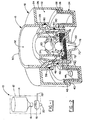
Fig. 1 is an illustrative view of a dispenser and liquid cartridge employing the bifurcated foam pump assembly of the invention; and -
Fig. 2 is a cross sectional view of the bifurcated foam pump assembly of the invention. - Referring now to the drawings and more particularly
Fig. 1 , it can be seen that a foam solution dispenser employing the bifurcated foam pump assembly of the invention is designated generally by thenumeral 10. It will be appreciated that the foam solution dispenser may be of any of various types, adapted for dispensing soap, lotion, sanitizers, cleaners or the like in the form of a foam. Thedispenser 10 includes ahousing 12, typically of molded plastic or the like. Thehousing 12 defines a cavity which is adapted to receive a bottle orcartridge 14 of a set volume of a liquid of the particular type required for generating the desired foam. The bottle orcartridge 14 is nestingly received by thehousing 10 and, as will be readily appreciated by those skilled in the art, is received and contained by supporting brackets, collars and the like within thehousing 12. - A
liquid pump 16 is connected to and provided as a portion of the disposable refill cartridge orbottle 14. In contradistinction, anair compressor unit 18 is provided as part and parcel of thedispenser housing 12. Alternatively, theair compressor 18 or the liquid pump16 may include a dispensingnozzle 20, through which the generated foam is dispensed onto the hand of the user, utensil, or otherwise. - A
suitable actuator 22 is operatively connected to theair compressor 18 to achieve actuation of the foam generator comprising the combination of theliquid pump 16 andair compressor 18. Those skilled in the art will understand that foam is typically generated from a combination of air and liquid, with the two being forced together, agitated, stirred, forcefully blended, or the like. Theactuator 22 may be either manually actuated as in the case of a lever, push bar, or the like, or it may be electronically or optically actuated as in the implementation of touch free dispensers. - It will be appreciated that a concept of the invention, as particularly presented below, is the implementation and utilization of a bifurcated foam pump assembly, in which the liquid pump portion is attached to and made a portion of the disposable and
replaceable cartridge 14, containing the liquid ingredient of the foam solution, while theair compressor 18 and associatednozzle 20 are not disposable, but remain a portion of thedispenser housing 12. - Referring now to
Fig. 2 , an appreciation can be obtained of the bifurcated liquid pump and air compressor assembly, and wherein the two are shown in the operative engagement achieved when thereplaceable cartridge 14 withliquid pump 16 attached thereto is matingly received by theair compressor 18 and attachednozzle 20 that are received by and maintained as a portion of thedispenser housing 12. As can be seen inFig. 2 , theair compressor 18 includes anannular collar 24 that is formed from anouter ring 26 and an inner ring established by first and secondstepped walls cavity 32 is defined between theouter ring 26 and the inner ring formed by the interconnectedwalls piston 34, consisting of anouter piston sleeve 36 and aninner piston sleeve 38 is received within thecavity 32 of theannular collar 24 and is adapted to operate between theouter ring 26 and one of the steppedinner rings 30. As will be readily appreciated by those skilled in the art, thepiston assembly 34 is adapted for reciprocation within thecavity 32. The extending motion of thepiston 34 is limited bystops annular collar 24 andpiston assembly 34, as shown. It will also be appreciated that the inward compressive movement of thepiston 34 may be limited in various similar ways, including a limitation on the movement of theactuator 22. - A one
way inlet valve 44 is provided in a base portion of thepiston 34, to allow air to reenter the air chamber orcavity 32 during operation, as will become apparent herein. It will also be noted that anoutlet aperture 46 is provided in thewall 30 of theannular collar 24, to allow communication between the air chamber orcavity 32 and the liquid pump assembly, as will be discussed below. - With continued reference to
Fig. 2 , it can be seen that theliquid pump 16 includes acollar 50 which is appropriately received by the throat of the disposable cartridge orcontainer 14. The collar defines acavity 52 and is characterized by an upwardly extending truncatedconical valve seat 54 at a bottom portion thereof, as shown. The various ribs and rings illustrated as comprising a portion of thecollar 50 are primarily interposed for purposes of strength and rigidity as will be readily appreciated by those skilled in the art. According to a preferred embodiment of the invention, thecollar 50, as with the majority of the components of the invention, are molded of an appropriate plastic. - An
intermediate cap 56 is attached to and closes an end of thecollar 50 to define a liquid dispensingcavity 58 therebetween. Aball valve 60 is received within thecavity 58 and is adapted to sealingly nest with thevalve seat 54 during operation, and as will become apparent below. Asecond valve seat 62, again of a truncated conical nature, is formed as part and parcel of theintermediate cap 56, as shown, and operates as the seat for an outlet valve as will become apparent below. - An annular recess or cavity 64 is provided about the interior wall surface of the
cap 56 to provide a ring-like passage between anaperture 66 provided through the wall of thecap 56 and the aperture 68 provided through the wall of thecollar 50. Accordingly, there is a passage for communication between theair chamber cavity 32 and theliquid chamber cavity 58 through theapertures - A
nozzle 20 is received by and closes the end of theintermediate cap 56, as shown inFig. 2 . Acavity 70 is thus defined between thenozzle 20 and theintermediate cap 56. This outlet chamber orcavity 70 receives an appropriate sponge, screen, mesh assembly, or the like to assist in the generation of foam as a mixture of air from the air chamber orcavity 32 and liquid from the liquid chamber orcavity 58. Aball valve 74 is received by thecavity 70 and is urged by the resilient nature of the sponge, screen, ormesh assembly 72 into nesting sealing engagement with thevalve seat 62, at rest. For this purpose, anappropriate recess 76 may be provided in theelement 72. - It will be appreciated that the elements comprising the
liquid pump 16 are attached to and are a part of therefill cartridge 14 and are received by theannular collar 24 and the remainder of the air chamber orcompressor 18 when replacement of therefill cartridge 14 is effected. To that end, appropriate O-ring seals 80 are received within the first andsecond walls collar 24. This allows for and ensures that the passage of liquid from thecontainer 14 only occurs after it is converted to foam for dispensing through theoutlet 78 of thenozzle 22. - In operation, the liquid of the
cartridge 14 that is required for generating the desired foam passes from thecontainer 14 through thecavity 52 of thecollar 50 and, by gravity, passes the seat andball valve arrangement liquid cavity 58 to await a dispensing operation. The seat andball valve element 72. When a dispensing operation is initiated as by theactuator 22, thepiston 34 moves from engagement between thestops cavity 32, forcefully passing that air through theapertures liquid chamber 58. This compressed air forces theball valve 60 into sealing engagement with thevalve seat 54 and urges theball valve 74 to disengage from theseat 62 against the biasing of the screen, sponge ormesh 72. A mixture of air and liquid is then forced through the valve assembles 62, 74 and through thefoam generating member 72 such that an appropriate foam is emitted through theoutlet 78 and onto the hands of the user or a desired tool or implement. At the end of the dispensing cycle, appropriate springs or biasing devices theactuator 22 cause thepiston 34 to retract from thecavity 32 until contact is made between thestops way valve 44 into the expandingcavity 32 to await the next cycle of operation. Liquid is replenished from thecontainer 14 through thevalve assembly cavity 58 is replenished. The bifurcated foam pump assembly comprising theliquid pump 16 and theair compressor 18 then awaits the next dispensing cycle. - Thus it can be seen that the various aspects of the invention have been achieved by the structure presented and described above. Only the liquid portion of the foam generator is required for replacement upon depletion of the
cartridge 14, rather than total replacement of the assembly as with prior art devices. Additionally, the bifurcated foam pump assembly is reliable and durable in use, theelement 72 being of sufficient strength and durability to accommodate depletion of thecartridge 14 while generating a high quality foam. - While in accordance with the patent statutes only the best mode and preferred embodiment of the invention has been presented and described in detail, the invention is not limited thereto or thereby. Accordingly, for an appreciation of the true scope and breadth of the invention reference should be made to the following claims.
Claims (6)
- A foam dispenser (10) comprising a dispenser housing (12) including an actuator, said dispenser housing (12) receiving a liquid cartridge (14), and a bifurcated, i.e. separated, foam pump assembly, comprising:a liquid pump portion (16) connected to the liquid cartridge (14), said liquid pump portion (16) separably mating with an air compressor portion (18)
characterized in that said air compressor portion (18) attached to and maintained as a portion of the dispenser housing (12) when replacement of the liquid cartridge (14) is effected. - The foam dispenser (10) according to claim 1, wherein the actuator drives the air compressor (18), and the air compressor (18) effects passage of both air and liquid through a foam generating member.
- The foam dispenser (10) according to claim 2, wherein said air compressor (18) comprises a piston (34) reciprocatingly movable in an air chamber (32), and wherein said liquid pump portion (16) comprises a liquid chamber (58), filled with liquid by gravity.
- The foam dispenser (10) according to claim 3, wherein said air chamber (32) communicates with said liquid chamber (58) through an air passage and wherein said liquid chamber (58) has an inlet valve (60) and an outlet valve (74), said inlet valve being closed and said outlet valve opened by passage of compressed air from said air chamber (32) to said liquid chamber (58) through said passage.
- The foam dispenser (10) according to claim 4, wherein said inlet valve (60) is normally open by gravity, and said outlet valve (74) is normally biased closed.
- The foam dispenser (10) according to claim 5, wherein said foam generating member biases said outlet valve (74) closed.
Priority Applications (2)
| Application Number | Priority Date | Filing Date | Title |
|---|---|---|---|
| EP12167527.6A EP2486835B1 (en) | 2008-02-08 | 2009-02-05 | A refill unit |
| EP11172819A EP2374386A3 (en) | 2008-02-08 | 2009-02-05 | Bifurcated foam pump assembly |
Applications Claiming Priority (1)
| Application Number | Priority Date | Filing Date | Title |
|---|---|---|---|
| US12/069,321 US8313010B2 (en) | 2008-02-08 | 2008-02-08 | Bifurcated foam pump assembly |
Related Child Applications (1)
| Application Number | Title | Priority Date | Filing Date |
|---|---|---|---|
| EP11172819.2 Division-Into | 2011-07-06 |
Publications (3)
| Publication Number | Publication Date |
|---|---|
| EP2087825A2 EP2087825A2 (en) | 2009-08-12 |
| EP2087825A3 EP2087825A3 (en) | 2009-12-09 |
| EP2087825B1 true EP2087825B1 (en) | 2011-09-28 |
Family
ID=40589544
Family Applications (3)
| Application Number | Title | Priority Date | Filing Date |
|---|---|---|---|
| EP12167527.6A Not-in-force EP2486835B1 (en) | 2008-02-08 | 2009-02-05 | A refill unit |
| EP11172819A Withdrawn EP2374386A3 (en) | 2008-02-08 | 2009-02-05 | Bifurcated foam pump assembly |
| EP09152143A Not-in-force EP2087825B1 (en) | 2008-02-08 | 2009-02-05 | Bifurcated foam pump assembly |
Family Applications Before (2)
| Application Number | Title | Priority Date | Filing Date |
|---|---|---|---|
| EP12167527.6A Not-in-force EP2486835B1 (en) | 2008-02-08 | 2009-02-05 | A refill unit |
| EP11172819A Withdrawn EP2374386A3 (en) | 2008-02-08 | 2009-02-05 | Bifurcated foam pump assembly |
Country Status (15)
| Country | Link |
|---|---|
| US (1) | US8313010B2 (en) |
| EP (3) | EP2486835B1 (en) |
| JP (1) | JP5412126B2 (en) |
| KR (1) | KR20090086335A (en) |
| CN (1) | CN101503134B (en) |
| AT (1) | ATE525946T1 (en) |
| AU (1) | AU2009200394B2 (en) |
| BR (1) | BRPI0900101A2 (en) |
| CA (1) | CA2652178C (en) |
| DK (2) | DK2087825T3 (en) |
| ES (2) | ES2371318T3 (en) |
| HK (2) | HK1131022A1 (en) |
| MY (1) | MY154488A (en) |
| PT (2) | PT2087825E (en) |
| TW (1) | TWI481426B (en) |
Families Citing this family (21)
| Publication number | Priority date | Publication date | Assignee | Title |
|---|---|---|---|---|
| US8047404B2 (en) * | 2008-02-08 | 2011-11-01 | Gojo Industries, Inc. | Bifurcated stem foam pump |
| US8167168B2 (en) * | 2009-09-17 | 2012-05-01 | Gojo Industries, Inc. | Dispenser with an automatic pump output detection system |
| US20110132931A1 (en) * | 2009-12-07 | 2011-06-09 | Shelley Lynn Wright | Interactive children's hand sanitizer |
| WO2011079301A1 (en) * | 2009-12-24 | 2011-06-30 | Geraghty, Erin | Container cap |
| US8550307B2 (en) * | 2011-03-31 | 2013-10-08 | Brightwell Dispensers Limited | Dispensing device with a disposable pump |
| US8651337B2 (en) * | 2011-04-22 | 2014-02-18 | Gojo Industries, Inc. | Foam dispenser having selectively pressurized container |
| US8662355B2 (en) * | 2011-08-11 | 2014-03-04 | Gojo Industries, Inc. | Split body pumps for foam dispensers and refill units |
| US8955769B2 (en) * | 2011-12-02 | 2015-02-17 | Gojo Industries, Inc. | Vortex atomizing foam pump and refill unit utilizing same |
| US8875952B2 (en) | 2012-03-12 | 2014-11-04 | Gojo Industries, Inc. | Air-activated sequenced valve split foam pump |
| US9611839B2 (en) | 2012-05-09 | 2017-04-04 | Gojo Industries, Inc. | Low residual inverted pumps, dispensers and refill units |
| US9027797B2 (en) | 2013-01-23 | 2015-05-12 | Gojo Industries, Inc. | Shield for a fluid dispenser |
| US9254068B2 (en) * | 2013-01-25 | 2016-02-09 | Gojo Industries, Inc. | Sequenced adjustable volume pumps, refill units and dispensers |
| US8820585B1 (en) * | 2013-03-15 | 2014-09-02 | Pibed Limited | Foam dispenser with a porous foaming element |
| WO2015127346A2 (en) * | 2014-02-21 | 2015-08-27 | RLM Group Ltd. | Enhanced application of oil-based products from fluid containers |
| MY186715A (en) | 2014-10-02 | 2021-08-12 | Unilever Plc | Liquid dispenser with framed refill receiving bay |
| US10278549B1 (en) | 2016-10-31 | 2019-05-07 | Gpcp Ip Holdings Llc | Counter-mounted skincare product dispenser |
| AU2019229097B2 (en) * | 2018-03-02 | 2023-10-12 | Gojo Industries, Inc. | Outlet valve arrangements for enhanced pump efficiency |
| FR3085865B1 (en) * | 2018-09-18 | 2020-09-25 | Aptar France Sas | FLUID PRODUCT DISPENSER. |
| US20230046136A1 (en) * | 2021-08-12 | 2023-02-16 | II Gerald Ward | Flexible lid for fermentation container |
| US11744413B2 (en) | 2021-10-07 | 2023-09-05 | Deb Ip Limited | Dispenser assembly |
| US11744412B2 (en) | 2021-10-07 | 2023-09-05 | Deb Ip Limited | Dispenser system |
Family Cites Families (23)
| Publication number | Priority date | Publication date | Assignee | Title |
|---|---|---|---|---|
| ATE11727T1 (en) * | 1981-11-18 | 1985-02-15 | Cws Ag | DEVICE FOR THE FORMATION OF SOAP FOAM IN PORTIONS. |
| EP0196737B2 (en) * | 1985-01-28 | 1991-11-06 | Earl Wright Company | Foam dispensing device |
| JPS61178375U (en) * | 1985-04-23 | 1986-11-07 | ||
| US4957218A (en) * | 1986-07-28 | 1990-09-18 | Ballard Medical Products | Foamer and method |
| US5222633A (en) * | 1991-09-20 | 1993-06-29 | Jack W. Kaufman | Foam dispensing device |
| US5339988A (en) * | 1992-10-19 | 1994-08-23 | Ballard Medical Products | Disposable tray sump foamer, assembly and methods |
| US5445288A (en) * | 1994-04-05 | 1995-08-29 | Sprintvest Corporation Nv | Liquid dispenser for dispensing foam |
| DE9407178U1 (en) * | 1994-05-02 | 1994-07-07 | Reidel Hermann | Device for producing and dispensing foam |
| FR2719789B1 (en) * | 1994-05-10 | 1996-07-05 | Saint Laurent Parfums Yves | Device for dispensing a product mixed with a fluid, dispensing assembly comprising such a device. |
| CH688021A5 (en) * | 1994-07-18 | 1997-04-30 | Cws Ag | Apparatus for formation of soap scum and its use. |
| JP3558387B2 (en) * | 1994-11-04 | 2004-08-25 | 大和グラビヤ株式会社 | Fluid removal device |
| US5984146A (en) * | 1996-09-27 | 1999-11-16 | Kaufman; John G. | Dispenser having foamed output |
| US6082586A (en) * | 1998-03-30 | 2000-07-04 | Deb Ip Limited | Liquid dispenser for dispensing foam |
| US6612468B2 (en) * | 2000-09-15 | 2003-09-02 | Rieke Corporation | Dispenser pumps |
| US20050072805A1 (en) * | 2003-08-20 | 2005-04-07 | Matthews Shaun Kerry | Foam dispenser with rigid container |
| US20050115988A1 (en) | 2003-12-01 | 2005-06-02 | Brian Law | Multiple liquid foamer |
| CA2464905C (en) * | 2004-03-19 | 2008-12-23 | Hygiene-Technik Inc. | Dual component dispenser |
| CA2504989C (en) * | 2005-04-22 | 2013-03-12 | Gotohti.Com Inc. | Stepped pump foam dispenser |
| CA2513181C (en) * | 2005-07-25 | 2012-03-13 | Gotohti.Com Inc. | Antibacterial foam generator |
| GB2437510A (en) * | 2006-04-26 | 2007-10-31 | Packaging Innovation Ltd | Dispenser mechanism |
| US7735692B2 (en) * | 2006-10-10 | 2010-06-15 | Meadwestvaco Calmar, Inc. | Rotating dispenser head with locking and venting closure connector for an air foaming pump dispenser |
| US7735688B2 (en) * | 2006-10-10 | 2010-06-15 | Meadwestvaco Calmar, Inc. | Rotating collar and locking and venting closure connector for an air foaming pump dispenser |
| US8047404B2 (en) * | 2008-02-08 | 2011-11-01 | Gojo Industries, Inc. | Bifurcated stem foam pump |
-
2008
- 2008-02-08 US US12/069,321 patent/US8313010B2/en active Active
-
2009
- 2009-02-03 CA CA2652178A patent/CA2652178C/en active Active
- 2009-02-04 TW TW098103531A patent/TWI481426B/en not_active IP Right Cessation
- 2009-02-04 AU AU2009200394A patent/AU2009200394B2/en not_active Ceased
- 2009-02-05 DK DK09152143.5T patent/DK2087825T3/en active
- 2009-02-05 EP EP12167527.6A patent/EP2486835B1/en not_active Not-in-force
- 2009-02-05 DK DK12167527.6T patent/DK2486835T3/en active
- 2009-02-05 EP EP11172819A patent/EP2374386A3/en not_active Withdrawn
- 2009-02-05 BR BRPI0900101-8A patent/BRPI0900101A2/en not_active IP Right Cessation
- 2009-02-05 EP EP09152143A patent/EP2087825B1/en not_active Not-in-force
- 2009-02-05 PT PT09152143T patent/PT2087825E/en unknown
- 2009-02-05 AT AT09152143T patent/ATE525946T1/en not_active IP Right Cessation
- 2009-02-05 ES ES09152143T patent/ES2371318T3/en active Active
- 2009-02-05 PT PT121675276T patent/PT2486835E/en unknown
- 2009-02-05 ES ES12167527T patent/ES2433465T3/en active Active
- 2009-02-06 KR KR1020090009514A patent/KR20090086335A/en not_active Application Discontinuation
- 2009-02-06 MY MYPI20090473A patent/MY154488A/en unknown
- 2009-02-09 CN CN2009100069326A patent/CN101503134B/en not_active Expired - Fee Related
- 2009-02-09 JP JP2009027290A patent/JP5412126B2/en not_active Expired - Fee Related
- 2009-10-20 HK HK09109658.5A patent/HK1131022A1/en not_active IP Right Cessation
-
2012
- 2012-09-19 HK HK12109189.8A patent/HK1168266A1/en not_active IP Right Cessation
Also Published As
| Publication number | Publication date |
|---|---|
| CA2652178A1 (en) | 2009-08-08 |
| EP2486835B1 (en) | 2013-09-04 |
| CN101503134B (en) | 2012-10-03 |
| HK1168266A1 (en) | 2012-12-28 |
| PT2087825E (en) | 2011-10-24 |
| CN101503134A (en) | 2009-08-12 |
| EP2374386A2 (en) | 2011-10-12 |
| TW200934538A (en) | 2009-08-16 |
| ES2433465T3 (en) | 2013-12-11 |
| EP2374386A3 (en) | 2011-10-26 |
| CA2652178C (en) | 2017-03-07 |
| JP2009184734A (en) | 2009-08-20 |
| AU2009200394B2 (en) | 2014-09-11 |
| EP2486835A1 (en) | 2012-08-15 |
| PT2486835E (en) | 2013-10-16 |
| MY154488A (en) | 2015-06-30 |
| DK2486835T3 (en) | 2013-11-04 |
| TWI481426B (en) | 2015-04-21 |
| US20090200339A1 (en) | 2009-08-13 |
| ES2371318T3 (en) | 2011-12-29 |
| EP2087825A3 (en) | 2009-12-09 |
| US8313010B2 (en) | 2012-11-20 |
| KR20090086335A (en) | 2009-08-12 |
| HK1131022A1 (en) | 2010-01-15 |
| DK2087825T3 (en) | 2012-01-16 |
| JP5412126B2 (en) | 2014-02-12 |
| EP2087825A2 (en) | 2009-08-12 |
| BRPI0900101A2 (en) | 2009-09-29 |
| ATE525946T1 (en) | 2011-10-15 |
| AU2009200394A1 (en) | 2009-08-27 |
Similar Documents
| Publication | Publication Date | Title |
|---|---|---|
| EP2087825B1 (en) | Bifurcated foam pump assembly | |
| US9089860B2 (en) | Bifurcated foam pump, dispensers and refill units | |
| EP2087824B1 (en) | Disposable liquid container and foam pump dispenser | |
| EP2462852B1 (en) | A refill unit for a refillable foam dispenser housing | |
| AU2014208298B2 (en) | Bifurcated foam pump assembly | |
| AU2014253540B2 (en) | Bifurcated stem foam pump |
Legal Events
| Date | Code | Title | Description |
|---|---|---|---|
| PUAI | Public reference made under article 153(3) epc to a published international application that has entered the european phase |
Free format text: ORIGINAL CODE: 0009012 |
|
| AK | Designated contracting states |
Kind code of ref document: A2 Designated state(s): AT BE BG CH CY CZ DE DK EE ES FI FR GB GR HR HU IE IS IT LI LT LU LV MC MK MT NL NO PL PT RO SE SI SK TR |
|
| AX | Request for extension of the european patent |
Extension state: AL BA RS |
|
| PUAL | Search report despatched |
Free format text: ORIGINAL CODE: 0009013 |
|
| AK | Designated contracting states |
Kind code of ref document: A3 Designated state(s): AT BE BG CH CY CZ DE DK EE ES FI FR GB GR HR HU IE IS IT LI LT LU LV MC MK MT NL NO PL PT RO SE SI SK TR |
|
| AX | Request for extension of the european patent |
Extension state: AL BA RS |
|
| RIC1 | Information provided on ipc code assigned before grant |
Ipc: A47K 5/14 20060101AFI20090508BHEP Ipc: B05B 11/00 20060101ALI20091030BHEP |
|
| REG | Reference to a national code |
Ref country code: HK Ref legal event code: DE Ref document number: 1131022 Country of ref document: HK |
|
| 17P | Request for examination filed |
Effective date: 20100525 |
|
| 17Q | First examination report despatched |
Effective date: 20100701 |
|
| AKX | Designation fees paid |
Designated state(s): AT BE BG CH CY CZ DE DK EE ES FI FR GB GR HR HU IE IS IT LI LT LU LV MC MK MT NL NO PL PT RO SE SI SK TR |
|
| GRAP | Despatch of communication of intention to grant a patent |
Free format text: ORIGINAL CODE: EPIDOSNIGR1 |
|
| GRAS | Grant fee paid |
Free format text: ORIGINAL CODE: EPIDOSNIGR3 |
|
| DAC | Divisional application: reference to earlier application (deleted) | ||
| GRAA | (expected) grant |
Free format text: ORIGINAL CODE: 0009210 |
|
| AK | Designated contracting states |
Kind code of ref document: B1 Designated state(s): AT BE BG CH CY CZ DE DK EE ES FI FR GB GR HR HU IE IS IT LI LT LU LV MC MK MT NL NO PL PT RO SE SI SK TR |
|
| REG | Reference to a national code |
Ref country code: GB Ref legal event code: FG4D |
|
| REG | Reference to a national code |
Ref country code: CH Ref legal event code: EP |
|
| REG | Reference to a national code |
Ref country code: PT Ref legal event code: SC4A Free format text: AVAILABILITY OF NATIONAL TRANSLATION Effective date: 20111017 |
|
| REG | Reference to a national code |
Ref country code: IE Ref legal event code: FG4D |
|
| REG | Reference to a national code |
Ref country code: SE Ref legal event code: TRGR |
|
| REG | Reference to a national code |
Ref country code: DE Ref legal event code: R096 Ref document number: 602009002755 Country of ref document: DE Effective date: 20111124 |
|
| REG | Reference to a national code |
Ref country code: NO Ref legal event code: T2 Effective date: 20110928 |
|
| REG | Reference to a national code |
Ref country code: ES Ref legal event code: FG2A Ref document number: 2371318 Country of ref document: ES Kind code of ref document: T3 Effective date: 20111229 |
|
| REG | Reference to a national code |
Ref country code: NL Ref legal event code: T3 |
|
| REG | Reference to a national code |
Ref country code: DK Ref legal event code: T3 |
|
| REG | Reference to a national code |
Ref country code: HK Ref legal event code: GR Ref document number: 1131022 Country of ref document: HK |
|
| PG25 | Lapsed in a contracting state [announced via postgrant information from national office to epo] |
Ref country code: FI Free format text: LAPSE BECAUSE OF FAILURE TO SUBMIT A TRANSLATION OF THE DESCRIPTION OR TO PAY THE FEE WITHIN THE PRESCRIBED TIME-LIMIT Effective date: 20110928 Ref country code: LT Free format text: LAPSE BECAUSE OF FAILURE TO SUBMIT A TRANSLATION OF THE DESCRIPTION OR TO PAY THE FEE WITHIN THE PRESCRIBED TIME-LIMIT Effective date: 20110928 Ref country code: HR Free format text: LAPSE BECAUSE OF FAILURE TO SUBMIT A TRANSLATION OF THE DESCRIPTION OR TO PAY THE FEE WITHIN THE PRESCRIBED TIME-LIMIT Effective date: 20110928 |
|
| LTIE | Lt: invalidation of european patent or patent extension |
Effective date: 20110928 |
|
| PG25 | Lapsed in a contracting state [announced via postgrant information from national office to epo] |
Ref country code: AT Free format text: LAPSE BECAUSE OF FAILURE TO SUBMIT A TRANSLATION OF THE DESCRIPTION OR TO PAY THE FEE WITHIN THE PRESCRIBED TIME-LIMIT Effective date: 20110928 Ref country code: SI Free format text: LAPSE BECAUSE OF FAILURE TO SUBMIT A TRANSLATION OF THE DESCRIPTION OR TO PAY THE FEE WITHIN THE PRESCRIBED TIME-LIMIT Effective date: 20110928 Ref country code: GR Free format text: LAPSE BECAUSE OF FAILURE TO SUBMIT A TRANSLATION OF THE DESCRIPTION OR TO PAY THE FEE WITHIN THE PRESCRIBED TIME-LIMIT Effective date: 20111229 Ref country code: LV Free format text: LAPSE BECAUSE OF FAILURE TO SUBMIT A TRANSLATION OF THE DESCRIPTION OR TO PAY THE FEE WITHIN THE PRESCRIBED TIME-LIMIT Effective date: 20110928 Ref country code: CY Free format text: LAPSE BECAUSE OF FAILURE TO SUBMIT A TRANSLATION OF THE DESCRIPTION OR TO PAY THE FEE WITHIN THE PRESCRIBED TIME-LIMIT Effective date: 20110928 |
|
| REG | Reference to a national code |
Ref country code: AT Ref legal event code: MK05 Ref document number: 525946 Country of ref document: AT Kind code of ref document: T Effective date: 20110928 |
|
| PG25 | Lapsed in a contracting state [announced via postgrant information from national office to epo] |
Ref country code: IS Free format text: LAPSE BECAUSE OF FAILURE TO SUBMIT A TRANSLATION OF THE DESCRIPTION OR TO PAY THE FEE WITHIN THE PRESCRIBED TIME-LIMIT Effective date: 20120128 Ref country code: SK Free format text: LAPSE BECAUSE OF FAILURE TO SUBMIT A TRANSLATION OF THE DESCRIPTION OR TO PAY THE FEE WITHIN THE PRESCRIBED TIME-LIMIT Effective date: 20110928 Ref country code: CZ Free format text: LAPSE BECAUSE OF FAILURE TO SUBMIT A TRANSLATION OF THE DESCRIPTION OR TO PAY THE FEE WITHIN THE PRESCRIBED TIME-LIMIT Effective date: 20110928 |
|
| PG25 | Lapsed in a contracting state [announced via postgrant information from national office to epo] |
Ref country code: EE Free format text: LAPSE BECAUSE OF FAILURE TO SUBMIT A TRANSLATION OF THE DESCRIPTION OR TO PAY THE FEE WITHIN THE PRESCRIBED TIME-LIMIT Effective date: 20110928 Ref country code: RO Free format text: LAPSE BECAUSE OF FAILURE TO SUBMIT A TRANSLATION OF THE DESCRIPTION OR TO PAY THE FEE WITHIN THE PRESCRIBED TIME-LIMIT Effective date: 20110928 |
|
| PLBE | No opposition filed within time limit |
Free format text: ORIGINAL CODE: 0009261 |
|
| STAA | Information on the status of an ep patent application or granted ep patent |
Free format text: STATUS: NO OPPOSITION FILED WITHIN TIME LIMIT |
|
| PG25 | Lapsed in a contracting state [announced via postgrant information from national office to epo] |
Ref country code: PL Free format text: LAPSE BECAUSE OF FAILURE TO SUBMIT A TRANSLATION OF THE DESCRIPTION OR TO PAY THE FEE WITHIN THE PRESCRIBED TIME-LIMIT Effective date: 20110928 |
|
| 26N | No opposition filed |
Effective date: 20120629 |
|
| PG25 | Lapsed in a contracting state [announced via postgrant information from national office to epo] |
Ref country code: MC Free format text: LAPSE BECAUSE OF NON-PAYMENT OF DUE FEES Effective date: 20120229 |
|
| REG | Reference to a national code |
Ref country code: DE Ref legal event code: R097 Ref document number: 602009002755 Country of ref document: DE Effective date: 20120629 |
|
| PG25 | Lapsed in a contracting state [announced via postgrant information from national office to epo] |
Ref country code: MK Free format text: LAPSE BECAUSE OF FAILURE TO SUBMIT A TRANSLATION OF THE DESCRIPTION OR TO PAY THE FEE WITHIN THE PRESCRIBED TIME-LIMIT Effective date: 20110928 |
|
| PG25 | Lapsed in a contracting state [announced via postgrant information from national office to epo] |
Ref country code: BG Free format text: LAPSE BECAUSE OF FAILURE TO SUBMIT A TRANSLATION OF THE DESCRIPTION OR TO PAY THE FEE WITHIN THE PRESCRIBED TIME-LIMIT Effective date: 20111228 |
|
| PG25 | Lapsed in a contracting state [announced via postgrant information from national office to epo] |
Ref country code: MT Free format text: LAPSE BECAUSE OF FAILURE TO SUBMIT A TRANSLATION OF THE DESCRIPTION OR TO PAY THE FEE WITHIN THE PRESCRIBED TIME-LIMIT Effective date: 20110928 |
|
| REG | Reference to a national code |
Ref country code: CH Ref legal event code: PL |
|
| PG25 | Lapsed in a contracting state [announced via postgrant information from national office to epo] |
Ref country code: LI Free format text: LAPSE BECAUSE OF NON-PAYMENT OF DUE FEES Effective date: 20130228 Ref country code: CH Free format text: LAPSE BECAUSE OF NON-PAYMENT OF DUE FEES Effective date: 20130228 |
|
| PG25 | Lapsed in a contracting state [announced via postgrant information from national office to epo] |
Ref country code: TR Free format text: LAPSE BECAUSE OF FAILURE TO SUBMIT A TRANSLATION OF THE DESCRIPTION OR TO PAY THE FEE WITHIN THE PRESCRIBED TIME-LIMIT Effective date: 20110928 |
|
| PG25 | Lapsed in a contracting state [announced via postgrant information from national office to epo] |
Ref country code: LU Free format text: LAPSE BECAUSE OF NON-PAYMENT OF DUE FEES Effective date: 20120205 |
|
| PG25 | Lapsed in a contracting state [announced via postgrant information from national office to epo] |
Ref country code: HU Free format text: LAPSE BECAUSE OF FAILURE TO SUBMIT A TRANSLATION OF THE DESCRIPTION OR TO PAY THE FEE WITHIN THE PRESCRIBED TIME-LIMIT Effective date: 20090205 |
|
| PGFP | Annual fee paid to national office [announced via postgrant information from national office to epo] |
Ref country code: NL Payment date: 20150225 Year of fee payment: 7 Ref country code: IT Payment date: 20150220 Year of fee payment: 7 Ref country code: ES Payment date: 20150226 Year of fee payment: 7 Ref country code: NO Payment date: 20150226 Year of fee payment: 7 Ref country code: DK Payment date: 20150225 Year of fee payment: 7 Ref country code: IE Payment date: 20150227 Year of fee payment: 7 |
|
| PGFP | Annual fee paid to national office [announced via postgrant information from national office to epo] |
Ref country code: SE Payment date: 20150226 Year of fee payment: 7 |
|
| PGFP | Annual fee paid to national office [announced via postgrant information from national office to epo] |
Ref country code: BE Payment date: 20150226 Year of fee payment: 7 |
|
| REG | Reference to a national code |
Ref country code: FR Ref legal event code: PLFP Year of fee payment: 8 |
|
| PGFP | Annual fee paid to national office [announced via postgrant information from national office to epo] |
Ref country code: DE Payment date: 20160226 Year of fee payment: 8 |
|
| PG25 | Lapsed in a contracting state [announced via postgrant information from national office to epo] |
Ref country code: BE Free format text: LAPSE BECAUSE OF NON-PAYMENT OF DUE FEES Effective date: 20160229 |
|
| PGFP | Annual fee paid to national office [announced via postgrant information from national office to epo] |
Ref country code: PT Payment date: 20160121 Year of fee payment: 8 Ref country code: GB Payment date: 20160226 Year of fee payment: 8 Ref country code: FR Payment date: 20160217 Year of fee payment: 8 |
|
| REG | Reference to a national code |
Ref country code: NO Ref legal event code: MMEP Ref country code: DK Ref legal event code: EBP Effective date: 20160229 |
|
| REG | Reference to a national code |
Ref country code: SE Ref legal event code: EUG |
|
| PG25 | Lapsed in a contracting state [announced via postgrant information from national office to epo] |
Ref country code: NO Free format text: LAPSE BECAUSE OF NON-PAYMENT OF DUE FEES Effective date: 20160229 |
|
| REG | Reference to a national code |
Ref country code: NL Ref legal event code: MM Effective date: 20160301 |
|
| PG25 | Lapsed in a contracting state [announced via postgrant information from national office to epo] |
Ref country code: SE Free format text: LAPSE BECAUSE OF NON-PAYMENT OF DUE FEES Effective date: 20160206 |
|
| REG | Reference to a national code |
Ref country code: IE Ref legal event code: MM4A |
|
| PG25 | Lapsed in a contracting state [announced via postgrant information from national office to epo] |
Ref country code: IT Free format text: LAPSE BECAUSE OF NON-PAYMENT OF DUE FEES Effective date: 20160205 |
|
| PG25 | Lapsed in a contracting state [announced via postgrant information from national office to epo] |
Ref country code: DK Free format text: LAPSE BECAUSE OF NON-PAYMENT OF DUE FEES Effective date: 20160229 Ref country code: NL Free format text: LAPSE BECAUSE OF NON-PAYMENT OF DUE FEES Effective date: 20160301 Ref country code: IE Free format text: LAPSE BECAUSE OF NON-PAYMENT OF DUE FEES Effective date: 20160205 |
|
| PG25 | Lapsed in a contracting state [announced via postgrant information from national office to epo] |
Ref country code: ES Free format text: LAPSE BECAUSE OF NON-PAYMENT OF DUE FEES Effective date: 20160206 |
|
| REG | Reference to a national code |
Ref country code: DE Ref legal event code: R082 Ref document number: 602009002755 Country of ref document: DE Representative=s name: KLUNKER IP PATENTANWAELTE PARTG MBB, DE |
|
| REG | Reference to a national code |
Ref country code: DE Ref legal event code: R119 Ref document number: 602009002755 Country of ref document: DE |
|
| GBPC | Gb: european patent ceased through non-payment of renewal fee |
Effective date: 20170205 |
|
| PG25 | Lapsed in a contracting state [announced via postgrant information from national office to epo] |
Ref country code: PT Free format text: LAPSE BECAUSE OF NON-PAYMENT OF DUE FEES Effective date: 20170807 |
|
| REG | Reference to a national code |
Ref country code: FR Ref legal event code: ST Effective date: 20171031 |
|
| PG25 | Lapsed in a contracting state [announced via postgrant information from national office to epo] |
Ref country code: DE Free format text: LAPSE BECAUSE OF NON-PAYMENT OF DUE FEES Effective date: 20170901 Ref country code: FR Free format text: LAPSE BECAUSE OF NON-PAYMENT OF DUE FEES Effective date: 20170228 |
|
| PG25 | Lapsed in a contracting state [announced via postgrant information from national office to epo] |
Ref country code: GB Free format text: LAPSE BECAUSE OF NON-PAYMENT OF DUE FEES Effective date: 20170205 |