EP2087200B1 - Valve for equalizer sand screens - Google Patents
Valve for equalizer sand screens Download PDFInfo
- Publication number
- EP2087200B1 EP2087200B1 EP20070864271 EP07864271A EP2087200B1 EP 2087200 B1 EP2087200 B1 EP 2087200B1 EP 20070864271 EP20070864271 EP 20070864271 EP 07864271 A EP07864271 A EP 07864271A EP 2087200 B1 EP2087200 B1 EP 2087200B1
- Authority
- EP
- European Patent Office
- Prior art keywords
- valve member
- assembly
- pressure
- lock
- tubular string
- Prior art date
- Legal status (The legal status is an assumption and is not a legal conclusion. Google has not performed a legal analysis and makes no representation as to the accuracy of the status listed.)
- Active
Links
- 239000004576 sand Substances 0.000 title 1
- 239000012530 fluid Substances 0.000 claims abstract description 14
- 230000008859 change Effects 0.000 claims abstract description 6
- 230000004044 response Effects 0.000 claims description 7
- 238000004891 communication Methods 0.000 claims description 4
- 230000007246 mechanism Effects 0.000 claims description 3
- 230000000717 retained effect Effects 0.000 claims description 2
- 238000005381 potential energy Methods 0.000 claims 1
- 238000011144 upstream manufacturing Methods 0.000 abstract description 2
- 239000000463 material Substances 0.000 description 5
- 238000013461 design Methods 0.000 description 4
- 230000000903 blocking effect Effects 0.000 description 3
- 238000004519 manufacturing process Methods 0.000 description 3
- 238000000034 method Methods 0.000 description 3
- 238000002955 isolation Methods 0.000 description 2
- 230000000452 restraining effect Effects 0.000 description 2
- 230000015572 biosynthetic process Effects 0.000 description 1
- 230000006735 deficit Effects 0.000 description 1
- 238000005553 drilling Methods 0.000 description 1
- 230000000694 effects Effects 0.000 description 1
- 238000012986 modification Methods 0.000 description 1
- 230000004048 modification Effects 0.000 description 1
- 230000008569 process Effects 0.000 description 1
- 238000012552 review Methods 0.000 description 1
- 238000012216 screening Methods 0.000 description 1
- 238000007789 sealing Methods 0.000 description 1
- 239000007787 solid Substances 0.000 description 1
Images


Classifications
-
- E—FIXED CONSTRUCTIONS
- E21—EARTH OR ROCK DRILLING; MINING
- E21B—EARTH OR ROCK DRILLING; OBTAINING OIL, GAS, WATER, SOLUBLE OR MELTABLE MATERIALS OR A SLURRY OF MINERALS FROM WELLS
- E21B34/00—Valve arrangements for boreholes or wells
- E21B34/06—Valve arrangements for boreholes or wells in wells
- E21B34/10—Valve arrangements for boreholes or wells in wells operated by control fluid supplied from outside the borehole
- E21B34/102—Valve arrangements for boreholes or wells in wells operated by control fluid supplied from outside the borehole with means for locking the closing element in open or closed position
-
- E—FIXED CONSTRUCTIONS
- E21—EARTH OR ROCK DRILLING; MINING
- E21B—EARTH OR ROCK DRILLING; OBTAINING OIL, GAS, WATER, SOLUBLE OR MELTABLE MATERIALS OR A SLURRY OF MINERALS FROM WELLS
- E21B34/00—Valve arrangements for boreholes or wells
- E21B34/06—Valve arrangements for boreholes or wells in wells
- E21B34/14—Valve arrangements for boreholes or wells in wells operated by movement of tools, e.g. sleeve valves operated by pistons or wire line tools
-
- E—FIXED CONSTRUCTIONS
- E21—EARTH OR ROCK DRILLING; MINING
- E21B—EARTH OR ROCK DRILLING; OBTAINING OIL, GAS, WATER, SOLUBLE OR MELTABLE MATERIALS OR A SLURRY OF MINERALS FROM WELLS
- E21B43/00—Methods or apparatus for obtaining oil, gas, water, soluble or meltable materials or a slurry of minerals from wells
- E21B43/02—Subsoil filtering
- E21B43/08—Screens or liners
-
- E—FIXED CONSTRUCTIONS
- E21—EARTH OR ROCK DRILLING; MINING
- E21B—EARTH OR ROCK DRILLING; OBTAINING OIL, GAS, WATER, SOLUBLE OR MELTABLE MATERIALS OR A SLURRY OF MINERALS FROM WELLS
- E21B43/00—Methods or apparatus for obtaining oil, gas, water, soluble or meltable materials or a slurry of minerals from wells
- E21B43/12—Methods or apparatus for controlling the flow of the obtained fluid to or in wells
-
- E—FIXED CONSTRUCTIONS
- E21—EARTH OR ROCK DRILLING; MINING
- E21B—EARTH OR ROCK DRILLING; OBTAINING OIL, GAS, WATER, SOLUBLE OR MELTABLE MATERIALS OR A SLURRY OF MINERALS FROM WELLS
- E21B43/00—Methods or apparatus for obtaining oil, gas, water, soluble or meltable materials or a slurry of minerals from wells
- E21B43/14—Obtaining from a multiple-zone well
-
- Y—GENERAL TAGGING OF NEW TECHNOLOGICAL DEVELOPMENTS; GENERAL TAGGING OF CROSS-SECTIONAL TECHNOLOGIES SPANNING OVER SEVERAL SECTIONS OF THE IPC; TECHNICAL SUBJECTS COVERED BY FORMER USPC CROSS-REFERENCE ART COLLECTIONS [XRACs] AND DIGESTS
- Y10—TECHNICAL SUBJECTS COVERED BY FORMER USPC
- Y10T—TECHNICAL SUBJECTS COVERED BY FORMER US CLASSIFICATION
- Y10T137/00—Fluid handling
- Y10T137/8593—Systems
- Y10T137/86485—Line condition change responsive release of valve
Definitions
- the field of this invention relates to isolation valves for screens that allow the screens to be selectively closed to operate other equipment.
- the screen sections are provided with a non-perforated base pipe under the screen section that forces the fluid along an annular path between the base pipe and the screen until a restriction section is reached.
- the restriction section can be a spiral path that provides a flow restriction to the filtered fluid. After going through the spiral restriction section, the filtered fluid reaches the openings to go though the base pipe.
- a series of screens with the same or differing restrictions are arranged in an interval to distribute the incoming flow among all the screen sections by counteracting the tendency of the fluid to otherwise follow the path of least resistance and flow in the annular space outside all the screen sections until reaching the heel of a horizontal run and trying to go through the most uphole screen first.
- What is needed is a technique that keeps the inflow passage closed until the screens need to be put into service while ensuring that all the screens will go into service when needed because the openings will go to the open position when needed.
- the present invention relates to a valve design for the inflow openings in the screen sections that make up the screened interval that keep the screens closed for run in to prevent flow through them while at the same time allowing pressure to build up within the base pipes so that tools can be operated. When the applied pressure is relieved the valves can open so that the screens can become operative.
- a series of screens with restrictors to equalize flow through base pipe perforations downstream or upstream of each restrictor features a valve member in the openings so that the screens are closed to flow for run in.
- Pressure can be developed within the base pipe for operation of downhole equipment below the screens such as a mud motor or in the screen liner such as a packer with no need for an internal string or wash pipe.
- the openings can be opened selectively when the associated equipment connected to the base pipes has been operated.
- the valve member can be actuated to open in a variety of ways such as applied pressure, temperature or a change in well fluid condition.
- FIG. 1 is a section view of a horizontal run in a wellbore showing the screens that carry the valve of the present invention
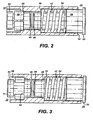
- FIG. 2 shows a valve locked in the closed position for isolation of its respective the screen
- FIG. 3 is the view of FIG. 2 with pressure applied to release the lock while the valve remains closed until pressure is relieved;
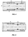
- FIG. 4 is an alternative embodiment to the valve of FIG. 2 shown in the locked closed position
- FIG. 5 is the valve of FIG. 4 unlocked but still held closed with applied pressure but in the position to spring open if pressure is removed;
- FIG. 6 shows the valve of FIG. 5 with pressure removed and the valve fully open
- FIG. 7 is an alternative embodiment using a shear pin to allow cycles of pressure below a threshold from moving the valve member
- FIG. 8 is the embodiment of FIG. 7 armed to open if pressure is removed
- FIG 9 is an alternative to the FIGS. 6-7 embodiment, in the run in position
- FIG. 10 is the view of FIG. 9 in the armed position
- FIG. 11 is the view of FIG. 10 in the valve open position
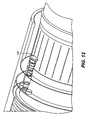
- FIG. 12 is a perspective view of a piston end of the FIG. 9 embodiment
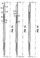
- FIG. 13 is an alternative embodiment shown in section during run in
- FIG. 14 is the view of FIG. 13 in the armed position
- FIG. 15 is the view of FIG.14 in the open position
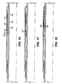
- FIG. 16 is an alternative embodiment shown in section during run in
- FIG. 17 is the view of FIG. 16 in the armed position
- FIG. 18 is the view of FIG. 17 in the open position.
- FIG. 1 illustrates a horizontal interval 10 that is uncased and has a series of Equalizer screens 12 and 14, for example connected to a production string 16.
- a packer 18 is connected to string 16.
- Base pipes 20 and 22 are solid.
- Annular spaces 24 and 26 lead to restrictors 28 and 30 respectively. These restrictors are essentially a spiral path whose dimensions determine resistance to the filtered fluid that has gotten through the screens 12 and 14. After passing through the restrictors 28 and 30, the filtered fluid enters annular spaces 32 or 34 to reach respectively the valves 36 and 38 that are a part of the present invention.
- valves 36 and 38 are closed, pressure in passage 40 can be built up so that, for example, the packer 18 can be set.
- the lower end can have a mud motor and drill bit attached so that drilling that brings the screens 12 and 14 into position in horizontal interval 10 can be accomplished and afterward the valves 36 and 38 can be operated to open so that fluid communication through screens 12 and 14 can begin into passage 40.
- valves 36 or 38 are run in closed and preferably locked in that position against opening.
- the valves move while remaining closed under increasing applied pressure.
- This feature allows internal pressure to build up in passage 40 to operate downhole tools, a few of which have been described above. Pressurizing also repositions the valves for subsequent opening.
- This can be configured in several ways. One way is to bias them so that removal of pressure the first time simply allows them all to open. Another way is to mount the valve members on a j-slot mechanism so that the pressure can be cycled off and on a predetermined amount of times before the valves go open. Another valve style altogether can be used so that the openings are blocked until a well condition changes so that the blocking material goes away.
- the well condition can be a change in temperature or pH that interacts with the blocking material to remove it.
- this latter technique is less preferred because it is not as simple to control the variables in the well. Additional, there is also the issue of the variability of the response of the valve material which could result in some openings being opened wide while others remain obstructed.
- FIG. 2 illustrates an opening 42 that leads from passage 40 to annulus 32 or 34 on the other end.
- Passage 42 is closed initially by plunger 44 that supports a seal 46 positioned in bore 48 of passage 42.
- Head 50 sees pressure built up in passage 40 and is limited in motion by surface 52 that surround passage 42.
- Spring 54 is supported by shoulder 56 to push the plunger 44 in the direction of passage 40.
- a c-ring 58 is held compressed in bore 60. In the compressed condition, the c-ring 58 will not allow bottom hub 62 to pass and this prevents spring 54 from moving seal 46 out of sealing position in bore 48.
- FIG. 2 illustrates an opening 42 that leads from passage 40 to annulus 32 or 34 on the other end.
- Passage 42 is closed initially by plunger 44 that supports a seal 46 positioned in bore 48 of passage 42.
- Head 50 sees pressure built up in passage 40 and is limited in motion by surface 52 that surround passage 42.
- Spring 54 is supported by shoulder 56 to push the plunger 44 in the direction of passage 40.
- hub 62 can clear through it but only after pressure on head 50 is reduced or removed. That lets spring 54 move plunger or valve member 44 enough to get seal 46 into taper 68 or bore 70 so that flow can commence in passage 42. At this time the plunger 44 can be pushed clear of passage 42 by spring 54 and the flowing fluid from annular space such as 32. Allowing the valve passage to open after applied pressure has been removed also prevents an undesirable pressure surge against the formation when the valves open, which may lead to production impairment.
- hub 62 can have a series of bores 72 and can be captured on bore 48 to retain the plunger 44 in passage 42 while still letting unhindered flow pass from the annular space such as 32 through the bores 72 and the now open passage 42.
- the c-ring 58 can be replaced with a j-slot mechanism between the plunger 44 and the passage 42 so that any number of desired pressure cycles could be applied to head 50 before the seal 46 is allowed to be displaced from bore 48.
- head 50 creates a travel stop under pressure in passage 40 to prevent bottoming the spring 54 or pushing seal 46 out of the bore 38.
- FIGS. 4 and 5 are basically the same design as FIGS. 2 and 3 with the exception that head 50 is not there. This allows the plunger 44' to enter bore 70' when pressure from passage 40 is applied. Otherwise the operation is the same. This design allows the coils of spring 54' being pushed together to act as a travel stop for the plunger 44'.
- FIG. 6 shows the embodiment of FIG. 3 and what happens after the pressure has been removed after that position is reached.
- the spring 54 expands to open bore 48 and let flow through the valve.
- FIGS. 7 and 8 show another embodiment that adds a shear pin 100, to act as a restraining member, so that pressure below the break point of the shear pin 100 can be applied to the heads 50 in as many cycles as needed without any movement occurring.
- Pin 100 is retained by ring 102 that is slidably inserted into the housing 104.
- each valve exposed to the tubing pressure can have a shear pin 100 but as seen in the other embodiments, such use is entirely optional.
- the pressure is simply raised to a point where all the shear pins 100 or equivalent structures used will all be broken and at that point the operation continues in the same manner described above.
- shear plane for pin 100 is at the interface of the outer surface 106 of piston 108 and the inner surface 110 of ring 102. When the pressure is relieved after the position of Figure 8 is achieved, this configuration will prevent jagged surfaces in the shear plane from impeding the bias force of spring 112 on piston 108.
- FIG. 9 shows a piston 114 having a seal 116 blocking a passage 118 for run in.
- a groove 120 traps an object 122 to resist the bias imposed by spring 124 on pin retainer ring 126.
- Ring 126 is not secured to housing 128 but has a lip 131 that limits its travel into housing 128 in response to applied pressure on head 130.
- Pin 132 initially holds ring 126 to the piston 114.
- Object 122 prevents piston 114 from being propelled out of passage 118. This is because opposite to groove 120 for run in is a step 134 that opens into a larger groove 136.
- Magnets 138 and 140 attract the objects 122 as piston 114 shifts under pressure to align the objects 122 with groove 136.
- FIG. 10 shows this position that is achieved by applying and holding pressure on head 130. What has happened is that the shear pin 132 is sheared and groove 120 has shifted left to align with groove 136 so that the magnetic force attracts the objects 122, which can be ball bearings or other shapes and materials that also respond to magnetic force.
- the removal of pressure on head 130 will allow spring 124 to propel both piston 114 and ring 126 out of passage 118 to the point where seal 116 is out of passage 118.
- FIG. 11 shows a perspective view of piston 114 showing a rectangular shape of head 130 as one way to limit its rotation about its own axis, which maintains alignment with the objects 122 and magnets 138.
- shear surface 142 (which is actually in the shape of a cylinder) where pin 132 is sheared is not the surface where subsequent relative movement occurs to eject piston 114 from passage 118. Instead, ring 126 moves with piston 114 so as to eliminate any resistance to relative movement that can occur at the shear surface 142 had the ring 126 been secured to the housing 128.
- the invention envisions a variety of ways to temporarily retain the piston 114 to get the result that the shear surface for a pin or equivalent restraining device 132 is not the sliding surface for ejection of the piston 114.
- base pipe 200 has openings 202 into annular space 204 defined by outer sleeve 206.
- a piston 208 is biased by a spring 210 but initially a snap ring 212 keeps piston 208 from moving in the direction of the bias.
- Piston 208 has seals 214 and 216 so that upon pressure delivered through openings 202 the piston 208 is able to translate in the direction to compress spring 210.
- the snap ring has snapped outwardly into a groove 218 so that it no longer interacts with the piston 208. No flow can get by the piston 208 and hence through the screen (not shown in these figures) because even in the FIG.
- FIG. 16 spring 224 bears on lug 226 attached to the base pipe 228. Pressure through openings 230 pushes piston 232 in a direction that compresses spring 224. At that time the snap ring 234 jumps out into groove 236 and as long as pressure is held in ports 230 there will be no flow past the piston 232. This is the view of FIG. 17 . When pressure is relieved, the spring 224 pushes the piston 232 so that flow can bypass piston seals 238 and 240 as shown in FIG. 18 .
- FIGS. 13-15 operates the same way as the alternative in FIGS. 16-18 except the spring support location.
- the FIGS. 16-18 embodiment allows for a bigger spring using the same outer sleeve dimension.
- the present invention allows equipment needing pressure to be operated without a wash pipe or an inner string while ensuring the openings open up when needed to allow proper screening of the produced fluids in the interval.
- pressure is let up, either the first time, after a pre-determined pressure level is applied to activate a shear device or after sufficient cycles, the valves will be biased to open.
- Each valve works independently of the others so that problems in the past with a series of rupture discs is avoided. Since applied pressure is uniform, its removal in the presence of a biasing member such as a spring results in the valves going to the open position independently.
Landscapes
- Life Sciences & Earth Sciences (AREA)
- Engineering & Computer Science (AREA)
- Geology (AREA)
- Mining & Mineral Resources (AREA)
- Physics & Mathematics (AREA)
- Environmental & Geological Engineering (AREA)
- Fluid Mechanics (AREA)
- General Life Sciences & Earth Sciences (AREA)
- Geochemistry & Mineralogy (AREA)
- Safety Valves (AREA)
- Quick-Acting Or Multi-Walled Pipe Joints (AREA)
- Non-Disconnectible Joints And Screw-Threaded Joints (AREA)
- Joints Allowing Movement (AREA)
- Flanged Joints, Insulating Joints, And Other Joints (AREA)
- Pipe Accessories (AREA)
- Sampling And Sample Adjustment (AREA)
- Control Of Fluid Pressure (AREA)
- Paper (AREA)
- Tone Control, Compression And Expansion, Limiting Amplitude (AREA)
- Filters And Equalizers (AREA)
- Preventing Unauthorised Actuation Of Valves (AREA)
Applications Claiming Priority (2)
| Application Number | Priority Date | Filing Date | Title |
|---|---|---|---|
| US11/598,508 US7775283B2 (en) | 2006-11-13 | 2006-11-13 | Valve for equalizer sand screens |
| PCT/US2007/084409 WO2008063947A1 (en) | 2006-11-13 | 2007-11-12 | Valve for equalizer sand screens |
Publications (2)
| Publication Number | Publication Date |
|---|---|
| EP2087200A1 EP2087200A1 (en) | 2009-08-12 |
| EP2087200B1 true EP2087200B1 (en) | 2011-01-05 |
Family
ID=39262795
Family Applications (1)
| Application Number | Title | Priority Date | Filing Date |
|---|---|---|---|
| EP20070864271 Active EP2087200B1 (en) | 2006-11-13 | 2007-11-12 | Valve for equalizer sand screens |
Country Status (11)
| Country | Link |
|---|---|
| US (1) | US7775283B2 (pt) |
| EP (1) | EP2087200B1 (pt) |
| AT (1) | ATE494454T1 (pt) |
| AU (1) | AU2007323940B2 (pt) |
| BR (1) | BRPI0718647B1 (pt) |
| CA (1) | CA2668475C (pt) |
| DE (1) | DE602007011803D1 (pt) |
| EG (1) | EG25857A (pt) |
| NO (1) | NO339173B1 (pt) |
| RU (1) | RU2441137C2 (pt) |
| WO (1) | WO2008063947A1 (pt) |
Families Citing this family (36)
| Publication number | Priority date | Publication date | Assignee | Title |
|---|---|---|---|---|
| US8936101B2 (en) | 2008-07-17 | 2015-01-20 | Halliburton Energy Services, Inc. | Interventionless set packer and setting method for same |
| US20080041588A1 (en) * | 2006-08-21 | 2008-02-21 | Richards William M | Inflow Control Device with Fluid Loss and Gas Production Controls |
| US20080041582A1 (en) * | 2006-08-21 | 2008-02-21 | Geirmund Saetre | Apparatus for controlling the inflow of production fluids from a subterranean well |
| US20080041581A1 (en) * | 2006-08-21 | 2008-02-21 | William Mark Richards | Apparatus for controlling the inflow of production fluids from a subterranean well |
| US8474535B2 (en) * | 2007-12-18 | 2013-07-02 | Halliburton Energy Services, Inc. | Well screen inflow control device with check valve flow controls |
| US7857061B2 (en) | 2008-05-20 | 2010-12-28 | Halliburton Energy Services, Inc. | Flow control in a well bore |
| US7814981B2 (en) * | 2008-08-26 | 2010-10-19 | Baker Hughes Incorporated | Fracture valve and equalizer system and method |
| US8469107B2 (en) * | 2009-12-22 | 2013-06-25 | Baker Hughes Incorporated | Downhole-adjustable flow control device for controlling flow of a fluid into a wellbore |
| US8469105B2 (en) * | 2009-12-22 | 2013-06-25 | Baker Hughes Incorporated | Downhole-adjustable flow control device for controlling flow of a fluid into a wellbore |
| US8210258B2 (en) * | 2009-12-22 | 2012-07-03 | Baker Hughes Incorporated | Wireline-adjustable downhole flow control devices and methods for using same |
| US8752629B2 (en) * | 2010-02-12 | 2014-06-17 | Schlumberger Technology Corporation | Autonomous inflow control device and methods for using same |
| US20110220367A1 (en) * | 2010-03-10 | 2011-09-15 | Halliburton Energy Services, Inc. | Operational control of multiple valves in a well |
| US8256522B2 (en) | 2010-04-15 | 2012-09-04 | Halliburton Energy Services, Inc. | Sand control screen assembly having remotely disabled reverse flow control capability |
| WO2011159523A2 (en) | 2010-06-14 | 2011-12-22 | Schlumberger Canada Limited | Method and apparatus for use with an inflow control device |
| US8910716B2 (en) | 2010-12-16 | 2014-12-16 | Baker Hughes Incorporated | Apparatus and method for controlling fluid flow from a formation |
| US20120168181A1 (en) * | 2010-12-29 | 2012-07-05 | Baker Hughes Incorporated | Conformable inflow control device and method |
| US8813857B2 (en) * | 2011-02-17 | 2014-08-26 | Baker Hughes Incorporated | Annulus mounted potential energy driven setting tool |
| US8403052B2 (en) | 2011-03-11 | 2013-03-26 | Halliburton Energy Services, Inc. | Flow control screen assembly having remotely disabled reverse flow control capability |
| US8485225B2 (en) | 2011-06-29 | 2013-07-16 | Halliburton Energy Services, Inc. | Flow control screen assembly having remotely disabled reverse flow control capability |
| BR112014016814A8 (pt) * | 2012-01-06 | 2017-07-04 | Weatherford Lamb Inc | dispositivo de ajuste de coluna interna de enchimento com cascalho |
| US9546529B2 (en) | 2012-02-01 | 2017-01-17 | Baker Hughes Incorporated | Pressure actuation enabling method |
| MX366532B (es) * | 2012-12-31 | 2019-07-12 | Halliburton Energy Services Inc | Dispositivo de control de flujo de entrada distribuido. |
| US10830028B2 (en) | 2013-02-07 | 2020-11-10 | Baker Hughes Holdings Llc | Frac optimization using ICD technology |
| US9617836B2 (en) | 2013-08-23 | 2017-04-11 | Baker Hughes Incorporated | Passive in-flow control devices and methods for using same |
| US20150083434A1 (en) * | 2013-09-20 | 2015-03-26 | Weatherford/Lamb, Inc. | Annular relief valve |
| NO3037552T3 (pt) * | 2013-10-03 | 2018-09-22 | ||
| AU2015384154B2 (en) | 2015-02-26 | 2018-06-07 | Halliburton Energy Services, Inc. | Pressure-controlled downhole actuators |
| US9850725B2 (en) | 2015-04-15 | 2017-12-26 | Baker Hughes, A Ge Company, Llc | One trip interventionless liner hanger and packer setting apparatus and method |
| US10428609B2 (en) | 2016-06-24 | 2019-10-01 | Baker Hughes, A Ge Company, Llc | Downhole tool actuation system having indexing mechanism and method |
| US20190048684A1 (en) * | 2017-08-08 | 2019-02-14 | Baker Hughes, A Ge Company, Llc | Unitary actuator valve for downhole operations |
| GB2586741B (en) | 2018-03-21 | 2023-01-18 | Baker Hughes Holdings Llc | Actuation trigger |
| US10648285B2 (en) * | 2018-05-18 | 2020-05-12 | Baker Hughes, A Ge Company, Llc | Fracturing system and method |
| US11066909B2 (en) | 2019-11-27 | 2021-07-20 | Halliburton Energy Services, Inc. | Mechanical isolation plugs for inflow control devices |
| CN112696343A (zh) * | 2020-12-30 | 2021-04-23 | 西南石油大学 | 页岩气水平井柱塞举升排水采气井下装置和工作方法 |
| US11952873B1 (en) | 2022-10-11 | 2024-04-09 | Halliburton Energy Services, Inc. | Washpipe free feature with ball and magnet |
| NO20221185A1 (en) * | 2022-11-03 | 2024-05-06 | Tco As | Flow Tube |
Family Cites Families (22)
| Publication number | Priority date | Publication date | Assignee | Title |
|---|---|---|---|---|
| US2707997A (en) | 1952-04-30 | 1955-05-10 | Zandmer | Methods and apparatus for sealing a bore hole casing |
| US2708000A (en) | 1952-06-18 | 1955-05-10 | Zandmer Solis Myron | Apparatus for sealing a bore hole casing |
| US2775304A (en) | 1953-05-18 | 1956-12-25 | Zandmer Solis Myron | Apparatus for providing ducts between borehole wall and casing |
| US2855049A (en) | 1954-11-12 | 1958-10-07 | Zandmer Solis Myron | Duct-forming devices |
| US3245472A (en) | 1961-05-23 | 1966-04-12 | Zandmer Solis Myron | Duct-forming devices |
| US3326291A (en) | 1964-11-12 | 1967-06-20 | Zandmer Solis Myron | Duct-forming devices |
| US3382926A (en) | 1966-01-05 | 1968-05-14 | Zandmer Solis Myron | Well completion device with acid soluble plug |
| US3347317A (en) | 1965-04-05 | 1967-10-17 | Zandmer Solis Myron | Sand screen for oil wells |
| US3434537A (en) | 1967-10-11 | 1969-03-25 | Solis Myron Zandmer | Well completion apparatus |
| US4285398A (en) | 1978-10-20 | 1981-08-25 | Zandmer Solis M | Device for temporarily closing duct-formers in well completion apparatus |
| US5375662A (en) * | 1991-08-12 | 1994-12-27 | Halliburton Company | Hydraulic setting sleeve |
| US5425424A (en) | 1994-02-28 | 1995-06-20 | Baker Hughes Incorporated | Casing valve |
| US5609178A (en) * | 1995-09-28 | 1997-03-11 | Baker Hughes Incorporated | Pressure-actuated valve and method |
| GB9715001D0 (en) | 1997-07-17 | 1997-09-24 | Specialised Petroleum Serv Ltd | A downhole tool |
| US6227298B1 (en) * | 1997-12-15 | 2001-05-08 | Schlumberger Technology Corp. | Well isolation system |
| US7198109B2 (en) * | 1998-08-21 | 2007-04-03 | Bj Services Company | Double-pin radial flow valve |
| US6397949B1 (en) * | 1998-08-21 | 2002-06-04 | Osca, Inc. | Method and apparatus for production using a pressure actuated circulating valve |
| AU2001286512A1 (en) * | 2000-08-31 | 2002-03-13 | Halliburton Energy Services, Inc. | Multi zone isolation tool and method for subterranean wells |
| US6983795B2 (en) * | 2002-04-08 | 2006-01-10 | Baker Hughes Incorporated | Downhole zone isolation system |
| US7503390B2 (en) * | 2003-12-11 | 2009-03-17 | Baker Hughes Incorporated | Lock mechanism for a sliding sleeve |
| US7210534B2 (en) * | 2004-03-09 | 2007-05-01 | Baker Hughes Incorporated | Lock for a downhole tool with a reset feature |
| US7409999B2 (en) * | 2004-07-30 | 2008-08-12 | Baker Hughes Incorporated | Downhole inflow control device with shut-off feature |
-
2006
- 2006-11-13 US US11/598,508 patent/US7775283B2/en active Active
-
2007
- 2007-11-12 AU AU2007323940A patent/AU2007323940B2/en active Active
- 2007-11-12 BR BRPI0718647-9A patent/BRPI0718647B1/pt active IP Right Grant
- 2007-11-12 AT AT07864271T patent/ATE494454T1/de not_active IP Right Cessation
- 2007-11-12 CA CA 2668475 patent/CA2668475C/en active Active
- 2007-11-12 WO PCT/US2007/084409 patent/WO2008063947A1/en active Application Filing
- 2007-11-12 EP EP20070864271 patent/EP2087200B1/en active Active
- 2007-11-12 DE DE200760011803 patent/DE602007011803D1/de active Active
- 2007-11-12 RU RU2009122218A patent/RU2441137C2/ru active
-
2009
- 2009-05-10 EG EG2009050676A patent/EG25857A/xx active
- 2009-05-19 NO NO20091940A patent/NO339173B1/no unknown
Also Published As
| Publication number | Publication date |
|---|---|
| DE602007011803D1 (de) | 2011-02-17 |
| RU2441137C2 (ru) | 2012-01-27 |
| WO2008063947A1 (en) | 2008-05-29 |
| EG25857A (en) | 2012-09-11 |
| ATE494454T1 (de) | 2011-01-15 |
| US7775283B2 (en) | 2010-08-17 |
| AU2007323940B2 (en) | 2012-12-06 |
| BRPI0718647B1 (pt) | 2018-02-14 |
| RU2009122218A (ru) | 2010-12-20 |
| NO339173B1 (no) | 2016-11-14 |
| BRPI0718647A2 (pt) | 2013-11-26 |
| CA2668475A1 (en) | 2008-05-29 |
| US20080135255A1 (en) | 2008-06-12 |
| EP2087200A1 (en) | 2009-08-12 |
| CA2668475C (en) | 2012-01-24 |
| NO20091940L (no) | 2009-08-12 |
| AU2007323940A1 (en) | 2008-05-29 |
Similar Documents
| Publication | Publication Date | Title |
|---|---|---|
| EP2087200B1 (en) | Valve for equalizer sand screens | |
| US9874067B2 (en) | Sliding sleeve sub and method and apparatus for wellbore fluid treatment | |
| US9664015B2 (en) | Fracturing system and method | |
| US9963953B2 (en) | Ball check valve integration to ICD | |
| US5947204A (en) | Production fluid control device and method for oil and/or gas wells | |
| US20090056952A1 (en) | Downhole Tool | |
| EP2971478B1 (en) | Expandable ball seat for hydraulically actuating tools | |
| US20130276901A1 (en) | Apparatus, Systems and Methods for a Flow Control Device | |
| US20200056467A1 (en) | Multi-stage hydraulic fracturing tool and system with releasable engagement | |
| CA2986352C (en) | Locking ring system for use in fracking operations | |
| CA2986346A1 (en) | Profile-selective sleeves for subsurface multi-stage valve actuation | |
| AU2017440345A1 (en) | Profile-selective sleeves for subsurface multi-stage valve actuation | |
| CA3030498C (en) | Collet with ball-actuated expandable seal and/or pressure augmented radially expandable splines | |
| AU2017440344A1 (en) | Locking ring system for use in fracking operations | |
| CA2846755A1 (en) | Fracturing system and method | |
| US20140090832A1 (en) | Mandrel Arrangement and Method of Operating Same |
Legal Events
| Date | Code | Title | Description |
|---|---|---|---|
| PUAI | Public reference made under article 153(3) epc to a published international application that has entered the european phase |
Free format text: ORIGINAL CODE: 0009012 |
|
| 17P | Request for examination filed |
Effective date: 20090525 |
|
| AK | Designated contracting states |
Kind code of ref document: A1 Designated state(s): AT BE BG CH CY CZ DE DK EE ES FI FR GB GR HU IE IS IT LI LT LU LV MC MT NL PL PT RO SE SI SK TR |
|
| DAX | Request for extension of the european patent (deleted) | ||
| GRAP | Despatch of communication of intention to grant a patent |
Free format text: ORIGINAL CODE: EPIDOSNIGR1 |
|
| GRAS | Grant fee paid |
Free format text: ORIGINAL CODE: EPIDOSNIGR3 |
|
| GRAA | (expected) grant |
Free format text: ORIGINAL CODE: 0009210 |
|
| AK | Designated contracting states |
Kind code of ref document: B1 Designated state(s): AT BE BG CH CY CZ DE DK EE ES FI FR GB GR HU IE IS IT LI LT LU LV MC MT NL PL PT RO SE SI SK TR |
|
| REG | Reference to a national code |
Ref country code: GB Ref legal event code: FG4D |
|
| REG | Reference to a national code |
Ref country code: CH Ref legal event code: EP |
|
| REG | Reference to a national code |
Ref country code: IE Ref legal event code: FG4D |
|
| REF | Corresponds to: |
Ref document number: 602007011803 Country of ref document: DE Date of ref document: 20110217 Kind code of ref document: P |
|
| REG | Reference to a national code |
Ref country code: DE Ref legal event code: R096 Ref document number: 602007011803 Country of ref document: DE Effective date: 20110217 |
|
| REG | Reference to a national code |
Ref country code: NL Ref legal event code: VDEP Effective date: 20110105 |
|
| PG25 | Lapsed in a contracting state [announced via postgrant information from national office to epo] |
Ref country code: SI Free format text: LAPSE BECAUSE OF FAILURE TO SUBMIT A TRANSLATION OF THE DESCRIPTION OR TO PAY THE FEE WITHIN THE PRESCRIBED TIME-LIMIT Effective date: 20110105 |
|
| LTIE | Lt: invalidation of european patent or patent extension |
Effective date: 20110105 |
|
| PG25 | Lapsed in a contracting state [announced via postgrant information from national office to epo] |
Ref country code: IS Free format text: LAPSE BECAUSE OF FAILURE TO SUBMIT A TRANSLATION OF THE DESCRIPTION OR TO PAY THE FEE WITHIN THE PRESCRIBED TIME-LIMIT Effective date: 20110505 Ref country code: SE Free format text: LAPSE BECAUSE OF FAILURE TO SUBMIT A TRANSLATION OF THE DESCRIPTION OR TO PAY THE FEE WITHIN THE PRESCRIBED TIME-LIMIT Effective date: 20110105 Ref country code: LV Free format text: LAPSE BECAUSE OF FAILURE TO SUBMIT A TRANSLATION OF THE DESCRIPTION OR TO PAY THE FEE WITHIN THE PRESCRIBED TIME-LIMIT Effective date: 20110105 Ref country code: GR Free format text: LAPSE BECAUSE OF FAILURE TO SUBMIT A TRANSLATION OF THE DESCRIPTION OR TO PAY THE FEE WITHIN THE PRESCRIBED TIME-LIMIT Effective date: 20110406 Ref country code: ES Free format text: LAPSE BECAUSE OF FAILURE TO SUBMIT A TRANSLATION OF THE DESCRIPTION OR TO PAY THE FEE WITHIN THE PRESCRIBED TIME-LIMIT Effective date: 20110416 Ref country code: PT Free format text: LAPSE BECAUSE OF FAILURE TO SUBMIT A TRANSLATION OF THE DESCRIPTION OR TO PAY THE FEE WITHIN THE PRESCRIBED TIME-LIMIT Effective date: 20110505 Ref country code: LT Free format text: LAPSE BECAUSE OF FAILURE TO SUBMIT A TRANSLATION OF THE DESCRIPTION OR TO PAY THE FEE WITHIN THE PRESCRIBED TIME-LIMIT Effective date: 20110105 |
|
| PG25 | Lapsed in a contracting state [announced via postgrant information from national office to epo] |
Ref country code: AT Free format text: LAPSE BECAUSE OF FAILURE TO SUBMIT A TRANSLATION OF THE DESCRIPTION OR TO PAY THE FEE WITHIN THE PRESCRIBED TIME-LIMIT Effective date: 20110105 Ref country code: CY Free format text: LAPSE BECAUSE OF FAILURE TO SUBMIT A TRANSLATION OF THE DESCRIPTION OR TO PAY THE FEE WITHIN THE PRESCRIBED TIME-LIMIT Effective date: 20110105 Ref country code: BG Free format text: LAPSE BECAUSE OF FAILURE TO SUBMIT A TRANSLATION OF THE DESCRIPTION OR TO PAY THE FEE WITHIN THE PRESCRIBED TIME-LIMIT Effective date: 20110405 Ref country code: BE Free format text: LAPSE BECAUSE OF FAILURE TO SUBMIT A TRANSLATION OF THE DESCRIPTION OR TO PAY THE FEE WITHIN THE PRESCRIBED TIME-LIMIT Effective date: 20110105 Ref country code: FI Free format text: LAPSE BECAUSE OF FAILURE TO SUBMIT A TRANSLATION OF THE DESCRIPTION OR TO PAY THE FEE WITHIN THE PRESCRIBED TIME-LIMIT Effective date: 20110105 Ref country code: NL Free format text: LAPSE BECAUSE OF FAILURE TO SUBMIT A TRANSLATION OF THE DESCRIPTION OR TO PAY THE FEE WITHIN THE PRESCRIBED TIME-LIMIT Effective date: 20110105 Ref country code: PL Free format text: LAPSE BECAUSE OF FAILURE TO SUBMIT A TRANSLATION OF THE DESCRIPTION OR TO PAY THE FEE WITHIN THE PRESCRIBED TIME-LIMIT Effective date: 20110105 |
|
| PG25 | Lapsed in a contracting state [announced via postgrant information from national office to epo] |
Ref country code: EE Free format text: LAPSE BECAUSE OF FAILURE TO SUBMIT A TRANSLATION OF THE DESCRIPTION OR TO PAY THE FEE WITHIN THE PRESCRIBED TIME-LIMIT Effective date: 20110105 Ref country code: DK Free format text: LAPSE BECAUSE OF FAILURE TO SUBMIT A TRANSLATION OF THE DESCRIPTION OR TO PAY THE FEE WITHIN THE PRESCRIBED TIME-LIMIT Effective date: 20110105 |
|
| PLBE | No opposition filed within time limit |
Free format text: ORIGINAL CODE: 0009261 |
|
| STAA | Information on the status of an ep patent application or granted ep patent |
Free format text: STATUS: NO OPPOSITION FILED WITHIN TIME LIMIT |
|
| PG25 | Lapsed in a contracting state [announced via postgrant information from national office to epo] |
Ref country code: CZ Free format text: LAPSE BECAUSE OF FAILURE TO SUBMIT A TRANSLATION OF THE DESCRIPTION OR TO PAY THE FEE WITHIN THE PRESCRIBED TIME-LIMIT Effective date: 20110105 Ref country code: RO Free format text: LAPSE BECAUSE OF FAILURE TO SUBMIT A TRANSLATION OF THE DESCRIPTION OR TO PAY THE FEE WITHIN THE PRESCRIBED TIME-LIMIT Effective date: 20110105 Ref country code: SK Free format text: LAPSE BECAUSE OF FAILURE TO SUBMIT A TRANSLATION OF THE DESCRIPTION OR TO PAY THE FEE WITHIN THE PRESCRIBED TIME-LIMIT Effective date: 20110105 |
|
| 26N | No opposition filed |
Effective date: 20111006 |
|
| REG | Reference to a national code |
Ref country code: DE Ref legal event code: R097 Ref document number: 602007011803 Country of ref document: DE Effective date: 20111006 |
|
| PG25 | Lapsed in a contracting state [announced via postgrant information from national office to epo] |
Ref country code: MC Free format text: LAPSE BECAUSE OF NON-PAYMENT OF DUE FEES Effective date: 20111130 |
|
| REG | Reference to a national code |
Ref country code: CH Ref legal event code: PL |
|
| PG25 | Lapsed in a contracting state [announced via postgrant information from national office to epo] |
Ref country code: CH Free format text: LAPSE BECAUSE OF NON-PAYMENT OF DUE FEES Effective date: 20111130 Ref country code: LI Free format text: LAPSE BECAUSE OF NON-PAYMENT OF DUE FEES Effective date: 20111130 |
|
| REG | Reference to a national code |
Ref country code: IE Ref legal event code: MM4A |
|
| REG | Reference to a national code |
Ref country code: DE Ref legal event code: R119 Ref document number: 602007011803 Country of ref document: DE Effective date: 20120601 |
|
| PG25 | Lapsed in a contracting state [announced via postgrant information from national office to epo] |
Ref country code: IE Free format text: LAPSE BECAUSE OF NON-PAYMENT OF DUE FEES Effective date: 20111112 |
|
| PG25 | Lapsed in a contracting state [announced via postgrant information from national office to epo] |
Ref country code: MT Free format text: LAPSE BECAUSE OF FAILURE TO SUBMIT A TRANSLATION OF THE DESCRIPTION OR TO PAY THE FEE WITHIN THE PRESCRIBED TIME-LIMIT Effective date: 20110105 |
|
| PG25 | Lapsed in a contracting state [announced via postgrant information from national office to epo] |
Ref country code: LU Free format text: LAPSE BECAUSE OF NON-PAYMENT OF DUE FEES Effective date: 20111112 |
|
| PG25 | Lapsed in a contracting state [announced via postgrant information from national office to epo] |
Ref country code: DE Free format text: LAPSE BECAUSE OF NON-PAYMENT OF DUE FEES Effective date: 20120601 |
|
| PG25 | Lapsed in a contracting state [announced via postgrant information from national office to epo] |
Ref country code: TR Free format text: LAPSE BECAUSE OF FAILURE TO SUBMIT A TRANSLATION OF THE DESCRIPTION OR TO PAY THE FEE WITHIN THE PRESCRIBED TIME-LIMIT Effective date: 20110105 |
|
| PG25 | Lapsed in a contracting state [announced via postgrant information from national office to epo] |
Ref country code: HU Free format text: LAPSE BECAUSE OF FAILURE TO SUBMIT A TRANSLATION OF THE DESCRIPTION OR TO PAY THE FEE WITHIN THE PRESCRIBED TIME-LIMIT Effective date: 20110105 |
|
| REG | Reference to a national code |
Ref country code: FR Ref legal event code: PLFP Year of fee payment: 9 |
|
| REG | Reference to a national code |
Ref country code: FR Ref legal event code: PLFP Year of fee payment: 10 |
|
| REG | Reference to a national code |
Ref country code: FR Ref legal event code: PLFP Year of fee payment: 11 |
|
| REG | Reference to a national code |
Ref country code: FR Ref legal event code: PLFP Year of fee payment: 12 |
|
| PGFP | Annual fee paid to national office [announced via postgrant information from national office to epo] |
Ref country code: FR Payment date: 20201021 Year of fee payment: 14 Ref country code: IT Payment date: 20201021 Year of fee payment: 14 |
|
| PG25 | Lapsed in a contracting state [announced via postgrant information from national office to epo] |
Ref country code: FR Free format text: LAPSE BECAUSE OF NON-PAYMENT OF DUE FEES Effective date: 20211130 |
|
| PG25 | Lapsed in a contracting state [announced via postgrant information from national office to epo] |
Ref country code: IT Free format text: LAPSE BECAUSE OF NON-PAYMENT OF DUE FEES Effective date: 20211112 |
|
| P01 | Opt-out of the competence of the unified patent court (upc) registered |
Effective date: 20230526 |
|
| PGFP | Annual fee paid to national office [announced via postgrant information from national office to epo] |
Ref country code: GB Payment date: 20231019 Year of fee payment: 17 |