EP2086775B1 - Apparatus and method for coupling a disconnectable stabilizer bar - Google Patents
Apparatus and method for coupling a disconnectable stabilizer bar Download PDFInfo
- Publication number
- EP2086775B1 EP2086775B1 EP07839928.4A EP07839928A EP2086775B1 EP 2086775 B1 EP2086775 B1 EP 2086775B1 EP 07839928 A EP07839928 A EP 07839928A EP 2086775 B1 EP2086775 B1 EP 2086775B1
- Authority
- EP
- European Patent Office
- Prior art keywords
- stabilizer bar
- transmission members
- plunger
- members
- sensor
- Prior art date
- Legal status (The legal status is an assumption and is not a legal conclusion. Google has not performed a legal analysis and makes no representation as to the accuracy of the status listed.)
- Active
Links
Images



Classifications
-
- B—PERFORMING OPERATIONS; TRANSPORTING
- B60—VEHICLES IN GENERAL
- B60G—VEHICLE SUSPENSION ARRANGEMENTS
- B60G21/00—Interconnection systems for two or more resiliently-suspended wheels, e.g. for stabilising a vehicle body with respect to acceleration, deceleration or centrifugal forces
- B60G21/02—Interconnection systems for two or more resiliently-suspended wheels, e.g. for stabilising a vehicle body with respect to acceleration, deceleration or centrifugal forces permanently interconnected
- B60G21/04—Interconnection systems for two or more resiliently-suspended wheels, e.g. for stabilising a vehicle body with respect to acceleration, deceleration or centrifugal forces permanently interconnected mechanically
- B60G21/05—Interconnection systems for two or more resiliently-suspended wheels, e.g. for stabilising a vehicle body with respect to acceleration, deceleration or centrifugal forces permanently interconnected mechanically between wheels on the same axle but on different sides of the vehicle, i.e. the left and right wheel suspensions being interconnected
- B60G21/055—Stabiliser bars
- B60G21/0551—Mounting means therefor
- B60G21/0553—Mounting means therefor adjustable
- B60G21/0556—Mounting means therefor adjustable including a releasable coupling
-
- B—PERFORMING OPERATIONS; TRANSPORTING
- B60—VEHICLES IN GENERAL
- B60G—VEHICLE SUSPENSION ARRANGEMENTS
- B60G17/00—Resilient suspensions having means for adjusting the spring or vibration-damper characteristics, for regulating the distance between a supporting surface and a sprung part of vehicle or for locking suspension during use to meet varying vehicular or surface conditions, e.g. due to speed or load
- B60G17/015—Resilient suspensions having means for adjusting the spring or vibration-damper characteristics, for regulating the distance between a supporting surface and a sprung part of vehicle or for locking suspension during use to meet varying vehicular or surface conditions, e.g. due to speed or load the regulating means comprising electric or electronic elements
- B60G17/016—Resilient suspensions having means for adjusting the spring or vibration-damper characteristics, for regulating the distance between a supporting surface and a sprung part of vehicle or for locking suspension during use to meet varying vehicular or surface conditions, e.g. due to speed or load the regulating means comprising electric or electronic elements characterised by their responsiveness, when the vehicle is travelling, to specific motion, a specific condition, or driver input
- B60G17/0162—Resilient suspensions having means for adjusting the spring or vibration-damper characteristics, for regulating the distance between a supporting surface and a sprung part of vehicle or for locking suspension during use to meet varying vehicular or surface conditions, e.g. due to speed or load the regulating means comprising electric or electronic elements characterised by their responsiveness, when the vehicle is travelling, to specific motion, a specific condition, or driver input mainly during a motion involving steering operation, e.g. cornering, overtaking
-
- B—PERFORMING OPERATIONS; TRANSPORTING
- B60—VEHICLES IN GENERAL
- B60G—VEHICLE SUSPENSION ARRANGEMENTS
- B60G21/00—Interconnection systems for two or more resiliently-suspended wheels, e.g. for stabilising a vehicle body with respect to acceleration, deceleration or centrifugal forces
- B60G21/10—Interconnection systems for two or more resiliently-suspended wheels, e.g. for stabilising a vehicle body with respect to acceleration, deceleration or centrifugal forces not permanently interconnected, e.g. operative only on acceleration, only on deceleration or only at off-straight position of steering
- B60G21/106—Interconnection systems for two or more resiliently-suspended wheels, e.g. for stabilising a vehicle body with respect to acceleration, deceleration or centrifugal forces not permanently interconnected, e.g. operative only on acceleration, only on deceleration or only at off-straight position of steering transversally
-
- B—PERFORMING OPERATIONS; TRANSPORTING
- B60—VEHICLES IN GENERAL
- B60G—VEHICLE SUSPENSION ARRANGEMENTS
- B60G3/00—Resilient suspensions for a single wheel
- B60G3/18—Resilient suspensions for a single wheel with two or more pivoted arms, e.g. parallelogram
- B60G3/20—Resilient suspensions for a single wheel with two or more pivoted arms, e.g. parallelogram all arms being rigid
-
- F—MECHANICAL ENGINEERING; LIGHTING; HEATING; WEAPONS; BLASTING
- F16—ENGINEERING ELEMENTS AND UNITS; GENERAL MEASURES FOR PRODUCING AND MAINTAINING EFFECTIVE FUNCTIONING OF MACHINES OR INSTALLATIONS; THERMAL INSULATION IN GENERAL
- F16D—COUPLINGS FOR TRANSMITTING ROTATION; CLUTCHES; BRAKES
- F16D27/00—Magnetically- or electrically- actuated clutches; Control or electric circuits therefor
- F16D27/10—Magnetically- or electrically- actuated clutches; Control or electric circuits therefor with an electromagnet not rotating with a clutching member, i.e. without collecting rings
- F16D27/118—Magnetically- or electrically- actuated clutches; Control or electric circuits therefor with an electromagnet not rotating with a clutching member, i.e. without collecting rings with interengaging jaws or gear teeth
-
- B—PERFORMING OPERATIONS; TRANSPORTING
- B60—VEHICLES IN GENERAL
- B60G—VEHICLE SUSPENSION ARRANGEMENTS
- B60G2202/00—Indexing codes relating to the type of spring, damper or actuator
- B60G2202/10—Type of spring
- B60G2202/13—Torsion spring
- B60G2202/135—Stabiliser bar and/or tube
-
- B—PERFORMING OPERATIONS; TRANSPORTING
- B60—VEHICLES IN GENERAL
- B60G—VEHICLE SUSPENSION ARRANGEMENTS
- B60G2202/00—Indexing codes relating to the type of spring, damper or actuator
- B60G2202/40—Type of actuator
- B60G2202/42—Electric actuator
-
- B—PERFORMING OPERATIONS; TRANSPORTING
- B60—VEHICLES IN GENERAL
- B60G—VEHICLE SUSPENSION ARRANGEMENTS
- B60G2202/00—Indexing codes relating to the type of spring, damper or actuator
- B60G2202/40—Type of actuator
- B60G2202/44—Axial actuator, e.g. telescopic
-
- B—PERFORMING OPERATIONS; TRANSPORTING
- B60—VEHICLES IN GENERAL
- B60G—VEHICLE SUSPENSION ARRANGEMENTS
- B60G2204/00—Indexing codes related to suspensions per se or to auxiliary parts
- B60G2204/40—Auxiliary suspension parts; Adjustment of suspensions
- B60G2204/419—Gears
-
- B—PERFORMING OPERATIONS; TRANSPORTING
- B60—VEHICLES IN GENERAL
- B60G—VEHICLE SUSPENSION ARRANGEMENTS
- B60G2204/00—Indexing codes related to suspensions per se or to auxiliary parts
- B60G2204/80—Interactive suspensions; arrangement affecting more than one suspension unit
- B60G2204/82—Interactive suspensions; arrangement affecting more than one suspension unit left and right unit on same axle
-
- B—PERFORMING OPERATIONS; TRANSPORTING
- B60—VEHICLES IN GENERAL
- B60G—VEHICLE SUSPENSION ARRANGEMENTS
- B60G2204/00—Indexing codes related to suspensions per se or to auxiliary parts
- B60G2204/80—Interactive suspensions; arrangement affecting more than one suspension unit
- B60G2204/83—Type of interconnection
-
- B—PERFORMING OPERATIONS; TRANSPORTING
- B60—VEHICLES IN GENERAL
- B60G—VEHICLE SUSPENSION ARRANGEMENTS
- B60G2401/00—Indexing codes relating to the type of sensors based on the principle of their operation
- B60G2401/17—Magnetic/Electromagnetic
- B60G2401/172—Hall effect
-
- B—PERFORMING OPERATIONS; TRANSPORTING
- B60—VEHICLES IN GENERAL
- B60G—VEHICLE SUSPENSION ARRANGEMENTS
- B60G2600/00—Indexing codes relating to particular elements, systems or processes used on suspension systems or suspension control systems
- B60G2600/08—Failure or malfunction detecting means
-
- B—PERFORMING OPERATIONS; TRANSPORTING
- B60—VEHICLES IN GENERAL
- B60G—VEHICLE SUSPENSION ARRANGEMENTS
- B60G2800/00—Indexing codes relating to the type of movement or to the condition of the vehicle and to the end result to be achieved by the control action
- B60G2800/01—Attitude or posture control
- B60G2800/012—Rolling condition
-
- F—MECHANICAL ENGINEERING; LIGHTING; HEATING; WEAPONS; BLASTING
- F16—ENGINEERING ELEMENTS AND UNITS; GENERAL MEASURES FOR PRODUCING AND MAINTAINING EFFECTIVE FUNCTIONING OF MACHINES OR INSTALLATIONS; THERMAL INSULATION IN GENERAL
- F16D—COUPLINGS FOR TRANSMITTING ROTATION; CLUTCHES; BRAKES
- F16D2300/00—Special features for couplings or clutches
- F16D2300/18—Sensors; Details or arrangements thereof
Definitions
- the present invention generally relates to vehicle suspension systems and more particularly to an anti-roll suspension system having a pair of independently mounted stabilizer bar halves that can be selectively de-coupled from one another, as per the preamble of claim 1.
- An example of such a system is disclosed in US 6 428 019 B1 .
- Traditional vehicle suspension systems include resilient devices, such as coil springs and leaf springs, to flexibly support a portion of a vehicle. These devices enable all of the vehicle wheels to maintain contract with the ground when traversing uneven terrain. Segregating the vehicle into unsprung and sprung portions in this manner is also useful for preventing severe impulsive forces from being transmitted to the vehicle occupants.
- the relatively stiff stabilizer bar tends to directly connect the vehicle wheels such that the motion of one wheel is copied to another wheel. If a vehicle so equipped was to strike a bump with one wheel, for example, the upward force (i.e., jounce) imparted to that wheel would be transmitted through the stabilizer bar to the opposite wheel, causing the opposite wheel to move in an upward direction. This "cross-talk" between the vehicle wheels can be undesirable.
- stabilizer bars Another drawback of stabilizer bars is that their torsional stiffness inhibits the free travel of the vehicle wheels. Modern materials and design techniques have substantially reduced the weight of the vehicle wheels and mounting structures to such an extent that the weight of a wheel and its mounting structure is typically insufficient to cause the stabilizer bar to rotate. While this problem is rarely, if ever, noticed on the relatively flat surfaces of modern roads, it can become apparent when the vehicle is operated over un-even terrain. In some situations, it is possible for one of the vehicle wheels to remain in an elevated position over a dip in the terrain due to the torsional resistance of the stabilizer bar. While situations of this severity are not routinely encountered, the fact remains that the stabilizer bar can reduce vehicle traction in some situations.
- the present teachings provide a stabilizer bar system including:
- the present teachings provide a method including:
- Figure 1 is a perspective view of a portion of a vehicle having an independent suspension with an anti-roll system constructed in accordance with the teachings of the present disclosure
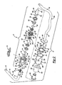
- Figure 2 is an exploded perspective view of the anti-roll system of Figure 1 ;
- Figure 3 is a section view taken longitudinally through a portion of the anti-roll system of Figure 1 illustrating the second transmission member in the engaged condition;
- Figure 4 is a section view similar to that of Figure 3 but illustrating the second transmission member in the disengaged condition
- Figure 5 is a longitudinal section view similar to that of Figure 3 but illustrating another anti-roll system constructed in accordance with the teachings of the present disclosure
- Figure 6 is a perspective view of a portion of the anti-roll system of Figure 5 in partial section illustrating the second transmission member and the controller assembly in greater detail;
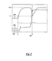
- Figure 7 is a plot of the electrical voltage and electrical current applied to the coil assembly of the anti-roll system of Figure 5 and the displacement of the plunger of the anti-roll system of Figure 5 as a function of time.
- an exemplary vehicle can include an independent front suspension system 10.
- the independent front wheel suspension can be of a type having suspension components at each wheel that are suspended from the vehicle frame structure 12.
- the frame structure 12 can include a pair of longitudinal side rails 14 and a crossbeam 16, but those of ordinary skill in the art will appreciate that the term "frame structure" need not refer to a frame as such, but could also refer to one or more regions of the vehicle body that act as an integrated frame structure.
- a front suspension system is illustrated and described herein, the teachings of the present disclosure are also applicable to a rear suspension system.
- the suspension system 10 can include a lower control arm 18 and an upper control arm 20.
- the lower and upper control arms 18 and 20 can be pivotally attached to the frame structure 12.
- a strut assembly which can have a helical coil spring 22 and a strut damper 24, can be retained between an intermediate portion of the lower control arm 18 and the frame structure 12 to support the weight of the vehicle body (not shown) and any loads that are transmitted through the lower control arm 18.
- the upper control arm 20 can be connected to the lower control arm 18 by a steering knuckle 26.
- a hub and rotor assembly 28 can be rotatably attached to a spindle portion (not specifically shown) of the steering knuckle 26 such that a wheel and tire (not shown) may be mounted thereon.
- the suspension system 10 can further include an anti-roll system 50 that can include a stabilizer bar assembly 52 and a pair of end links 54 that can connect the ends 56 of the stabilizer bar assembly 52 to the lower control arms 18.
- the stabilizer bar assembly 52 can include first and second stabilizer bar members 60a and 60b, respectively, a clutch assembly 62 and a controller assembly 64.
- the first stabilizer bar member 60a can be generally L-shaped, having an arm portion 70, which can have a mounting-portion 72, and a leg portion 74 that can be coupled to an end of the arm portion 70 opposite the mounting portion 72.
- the mounting portion 72 can be configured to be coupled to the frame structure 12 in a conventional manner, such as the end link 54.
- the leg portion 74 can be rotatably coupled to the frame structure 12 in a conventional manner (such as a bracket 76) and can include a coupling portion 78 that can couple the first stabilizer bar member 60a to the clutch assembly 62.
- the coupling portion 78 includes a journal 80, a coupling member 82 and a snap-ring groove 84 that is disposed on a side of the coupling member 82 opposite the journal 80.
- the coupling member 82 can have a non-circular shape and in the example provided, includes a plurality of longitudinally-extending teeth or splines 86.
- the second stabilizer bar member 60b can also be generally L-shaped and have an arm portion 90 and a leg portion 94.
- the arm portion 90 can be similar to the arm portion 70 of the first stabilizer bar member 60a.
- the leg portion 94 can be coupled to an end of the arm portion 90 and can include a coupling member 102 that can be employed to non-rotatably couple the second stabilizer bar member 60b to the clutch assembly 62.
- the coupling member 102 includes a flange 104 that can be fixedly coupled to the clutch assembly 62, as will be discussed in detail below, but those of ordinary skill in the art will appreciate that the coupling member 102 could be formed in any desired manner that permits the second stabilizer bar member 60b to be non-rotatably coupled to the clutch assembly 62.
- the clutch assembly 62 can include a housing assembly 120, a first transmission member 122, a second transmission member 124, a coil assembly 126, a plunger 128, a sleeve 130, a first spring 132, a second spring 134 and a retaining ring 136.
- the housing assembly 120 can include a first end cap 140, a second end cap 142 and a housing 144.
- the first end cap 140 can include a cap member 150, a pair of bearings 152 and a seal 154.
- the cap member 150 can be formed of any appropriate material and can include a body 160 and a flange 162.
- the body 160 can define a central bore 164, which can be oriented along a longitudinal axis of the cap member 150, a sensor boss 166, a pilot portion 168 and an end face 170.
- the sensor boss 166 can have a flat outer surface 172 and can define a sensor aperture 174 that can extend through a side of the body 160.
- the sensor aperture 174 can be disposed generally perpendicular to both the flat outer surface 172 and the central bore 164.
- the pilot portion 168 can be an annular structure that can be generally concentric with the central bore 164.
- the pilot portion 168 can cooperate with another portion of the cap member 150, such as the flange 162, to define a shoulder 180.
- the end face 170 can be an axial end face of a portion of the cap member 150, such as the pilot portion 168, and can be spaced axially apart from the shoulder 180.
- the flange 162 can be disposed about the body 160 and can include a plurality of bosses 182.
- the second end cap 142 can include a cap member 190 and a plunger backstop 192.
- the cap member 190 and the plunger backstop 192 are unitarily formed of an appropriate material, such as a magnetic ferrous-alloyed powdered metal, but it will be appreciated that they could be formed as discrete components that are coupled to one another to facilitate the manufacture of the second end cap 142 and/or the use of different materials for the cap member 190 and the plunger backstop 192.
- the cap member 190 can include a body 194 and a flange 196.
- the body 194 can define a coupling portion 200, a pilot portion 202 and an end face 204.
- the coupling portion 200 can be configured to engage the coupling member 102 of the second stabilizer bar member 60b such that the second stabilizer bar member 60b and the cap member 190 are non-rotatably coupled to one another.
- the pilot portion 202 can be a generally cylindrical structure and can cooperate with another portion of the cap member 190, such as the flange 196, to define a shoulder 206.
- the end face 204 can be an axial end face of a portion of the cap member 190, such as the pilot portion 202, and can be spaced axially apart from the shoulder 206.
- the flange 196 can be disposed about the body 194 and can include a plurality of bosses 208.
- the plunger backstop 192 can be a generally cylindrical structure that can be generally concentric with the pilot portion 202 and can project from the end face 204.
- the distal end 210 of the plunger backstop 192 can include a plunger aperture 212 that can be disposed about a longitudinal axis of the plunger backstop 192.
- the plunger aperture 212 has a frusto-conical shape having a cone angle 214 of about 60° to about 120° and a flat end wall 216.
- the housing 144 can include a body 220 and first and second end flanges 222 and 224, respectively.
- the body 220 can be a hollow generally cylindrical structure and can include a plurality of mounting pads 226, a bore 228, a first coupling member 230 and an interior wall 232.
- the mounting pads 226 can be formed on an exterior surface of the body 220 and can each include one or more threaded apertures 240.
- the bore 228 can be disposed longitudinally through the body 220 and can define a pilot bore 240, a first portion 242, a second portion 244 and a third portion 246 that can be concentric with one another.
- the pilot bore 240 can be sized and configured to receive the pilot portion 168 of the cap member 150 to align the central bore 164 concentrically with the bore 228.
- the first portion 242 can be sized to receive the second spring 134, the second portion 244 can be sized to receive the sleeve 130 and the third portion 246 can be sized to receive the coil assembly 126 and the pilot portion 202 of the cap member 190.
- the first coupling member 230 can include a plurality of circumferentially spaced-apart teeth or splines 250 that can be located axially between the pilot bore 240 and the first portion 242.
- the interior wall 232 can be disposed between the second and third portions 244 and 246 of the bore 228.
- An aperture 252 can be formed through the interior wall 232.
- the first and second end flanges 222 and 224 can be disposed about the body 220 and can each including a plurality of bosses 260.
- the bosses 182 and 208 of the flanges 162 and 196, respectively, can be aligned to the bosses 260 of the first and second end flanges 222 and 224, respectively, and threaded fasteners 262, such as cap screws, can be employed to fixedly but removably couple the first and second end caps 140 and 142 to the housing 144 such that the body 220 abuts the shoulders 180 and 206 of the cap members 150 and 190, respectively.
- a sleeve dowel 270 is fitted to a counter bore 272 that is formed in one of the bosses 260 in each of the first and second end flanges 222 and 224 as well as and an associated counter bore or through hole that is formed in the bosses 182 and 208 in the flanges 162 and 196.
- the sleeve dowels 270 can radially locate the first and second end caps 140 and 142 to the housing 144 such that the flat outer surface 172 of the sensor boss 166 is aligned in a predetermined manner to the mounting pads 226.
- the threaded fasteners 262 are also employed to fixedly but removably secure the flange 104 of the second stabilizer bar member 60b to the second end cap 142.
- the first transmission member 122 can be a hollow sleeve having an internal bore 300, a second coupling member 302 and a third coupling member 304.
- the first transmission member 122 can be rotatable but axially fixed to the first end cap 140.
- the first transmission member 122 is supported by the bearings 152 in the first end cap 140.
- the second coupling member 302 can engage the coupling member 82 of the first stabilizer bar member 60a to inhibit relative rotation therebetween.
- the second coupling member 302 can include a plurality of circumferentially spaced-apart longitudinally-extending teeth or splines 306, which are formed about the interior diameter of the internal bore 300, that can matingly engage the splines 86 of the coupling member 82 of the first stabilizer bar member 60a.
- the third coupling member 304 can have a non-circular shape and in the example provided, includes a plurality of longitudinally-extending teeth or splines 310.
- One of the splines 310 e.g., spline 310a
- the first stabilizer bar member 60a can be coupled to first transmission member 122 to inhibit relative axial movement therebetween.
- a snap ring 314 is received in the snap ring groove 84 and engages another groove 316 that is formed on the first transmission member 122.
- the second transmission member 124 can include a body 320, a fourth coupling member 322 and a fifth coupling member 324.
- the body 320 can include a bore 326 and one or more sensor targets 328.
- the bore 326 can include a pilot portion 330.
- the fourth coupling member 322 can be configured to selectively engage the third coupling member 304 of the first transmission member 122 to inhibit relative rotation therebetween.
- the fourth coupling member 322 can include a plurality of circumferentially spaced-apart longitudinally-extending teeth or splines 340, which are formed about the interior diameter of the bore 326, that can matingly engage the splines 310 of the third coupling member 304.
- the spacing between two of the splines 340 can be configured to receive the spline 310a to thereby key the third coupling member 304 to the fourth coupling member 322 (i.e., the splines 310 can mesh with the splines 340 in only one rotational position).
- the fifth coupling member 324 can have a non-circular shape and in the example provided, includes a plurality of longitudinally-extending teeth or splines 344.
- the sensor target 328 is an annular rim or projection that is disposed about the body 320 and which has first and second wall members 350 and 352, respectively, that are generally perpendicular to the bore 326.
- the second transmission member 124 can be disposed about the first transmission member 122 and can be received in the bores 164 and 228 such that the sensor target 328 is disposed in-line with the sensor aperture 174.
- the second transmission member 124 can be axially movable relative to the first transmission member 122 between a first or engaged position in which the fourth coupling member 322 is non-rotatably coupled to the third coupling member 304 as shown in Figure 3 , and a second or disengaged position in which the fourth coupling member 322 is decoupled from the third coupling member 304 to permit relative rotation between the first and second transmission members 122 and 124 as shown in Figure 4 .
- positioning of the second transmission member 124 in the first position can non-rotatably couple the first stabilizer bar member 60a to the housing 144 (and thereby to the second stabilizer bar member 60b), while positioning of the second transmission member 124 in the second position can decouple the first stabilizer bar member 60a from the housing 144 to thereby permit relative rotation between the first and second stabilizer bar members 60a and 60b.
- the coil assembly 126 can be disposed in the third portion 246 of the bore 228 in the housing 144 and can include an annular bobbin 400 and a coil of wire 402 that is wound around about the bobbin 400.
- the coil of wire 402 can include a pair of terminals 406 that are electrically coupled to the controller assembly 64.
- a first side of the coil assembly 126 can abut the interior wall 232 in the housing 144 and a second, opposite side of the coil assembly 126 can abut the end face 204 of the cap member 190.
- the portion of the coil assembly 126 adjacent the second end can be disposed about the plunger backstop 192.
- the plunger 128 can be a generally cylindrical shaft-like structure having a body portion 450 and a flange portion 452.
- the body portion 450 can have a tip 460 and a ring groove 462.
- the tip 460 can be configured in a manner that is complementary to the configuration of the plunger aperture 212 in the plunger backstop 192.
- the tip can has a frusto-conical shape with a cone angle 464 of about 60° to about 120°. It will be appreciated that the cone angle 464 and the cone angle 214 can be about equal.
- the ring groove 462 can be formed about the body portion 450 and can be sized to receive the retaining ring 136.
- a through-hole 466 can be formed through the body portion 450 and can be shaped and sized in any appropriate manner.
- the size and shape of the through-hole 466 can be selected to reduce or eliminate the build-up of pressure that might otherwise occur when the plunger 128 is translated and/or to reduce the overall mass of the plunger 128.
- the body portion 450 can be received into the bore 228 of the housing 144 and can extend through the aperture 252 in the interior wall 232.
- the flange portion 452 can be coupled to an end of the body portion 450 opposite the tip 460.
- the sleeve 130 can be an annular structure having a body 500 and a flange member 502.
- the body 500 can be fixedly coupled (e.g., press fit, welded) to the second transmission member 124 and can define an aperture 504 into which the end of the plunger 128 opposite the tip 460 is disposed.
- the flange member 502 can be coupled to an end of the body 500 opposite the second transmission member 124.
- the first spring 132 can be configured to bias the plunger 128 in a direction opposite the plunger backstop 192.
- the first spring 132 is a compression spring that is fitted about the body portion 450 of the plunger 128 between the flange portion 452 and the flange member 502 of the sleeve 130.
- the first spring 132 and the sleeve 130 can cooperate to couple the plunger 128 to the second transmission member 124.
- the second spring 134 can be configured to bias the second transmission member 124 toward the engaged position ( Fig. 3 ).
- the second spring 134 is a compression spring that is fitted about the sleeve 130 between a shoulder 520 in the housing 144 and an axial end face of the second transmission member 124.
- the retaining ring 136 can be disposed in the retaining ring groove 462 in the body portion 450 of the plunger 128 to limit the distance by which the flange member 502 of the sleeve 130 can be spaced apart from the flange portion 452 of the plunger 128.
- the controller assembly 64 can include a controller 600 and a controller housing 602.
- the controller 600 can include hardware for controlling the operation of the clutch assembly 62 and a sensor suite 606 having one or more sensors that sense various parameters or conditions of the clutch assembly 62, the vehicle V ( Fig. 1 ) and/or the environment.
- the sensor suite 606 includes a single back-biased Hall-effect sensor that is configured to sense the sensor target 328, such as an AT635LSETN-T sensor marketed by Allegro MicroSystems of Worcester Massachusetts, but those of ordinary skill in the art will appreciate that the number and type of sensors that are employed may be selected in accordance with a desired level (i.e., quantity and quality) of information relating to the operation of the anti-roll system 50.
- controller assembly 64 can operate the coil assembly 126 in a first mode to initiate movement of the second transmission member 124, and a second mode to maintain the second transmission member 124 in a desired position.
- the controller assembly 64 can provide DC electrical power of a predetermined voltage to the coil assembly 126 to operate it in the first mode, and can provide DC electrical power in a pulse-width-modulated (PWM) form to the coil assembly 126 to operate it in the second mode.
- PWM pulse-width-modulated
- the supply of electrical power to the coil assembly 126 in a PWM form is desirable as it reduces overall energy consumption and generates relatively lower amounts of heat as compared to straight DC electrical power. It will be appreciated that electrical power may be transmitted to the coil assembly 126 in a PWM form during the first mode and that the duty cycle employed for the first and second modes can be different.
- the controller housing 602 can be a metallic or plastic enclosure that is configured to sealingly enclose the controller 600 therein.
- the controller housing 602 is a box-like structure having a plurality of mounting bosses 610 that are employed to fixedly but removably couple the controller housing 602 to the mounting pads 226 of the housing 144 via threaded fasteners (not shown).
- the sensor suite 606 can extend from a lower wall 612 of the controller housing 602 and can be received into the sensor aperture 174 in the sensor boss 166.
- One or more resilient seal members can be employed to form a seal between the controller 600 and the housing assembly 120 to thereby inhibit the ingress of dirt, debris and moisture into the controller 600 and/or the housing assembly 120.
- a connector 616 which can be coupled to the controller 600, can extend through an upper wall 618 of the controller housing 602.
- the connector 616 can facilitate the electrical coupling of the controller 600 to a power source (not shown) and to a vehicle controller/car area network (CAN)(not shown) to permit electrical power and appropriate data to be transmitted to the controller 600 and/or from the controller 600 to the CAN.
- the controller 600 can be electrically coupled to the terminals 406 of the coil of wire 402.
- the second spring 134 biases the second transmission member 124 toward the first position so that the third and fourth coupling members 304 and 322 are engaged to one another to thereby couple the first and second stabilizer bar members 60a and 60b with one another.
- movement of the first and second stabilizer bar members 60a and 60b relative to one another will transmit torque through the clutch assembly 62.
- Torque can be transmitted concentrically through the clutch assembly 62 (i.e., evenly about the axis along which the second transmission member 124 slides, which in the example provided is the longitudinal axis of the bore 228 in the housing 144) so that the various translating components, such as the second transmission member 124, are not subjected to side-loads:
- the controller assembly 64 can energize the coil assembly 126 to cause the plunger 128 to move toward the plunger backstop 192 and compress the first spring 132.
- the force exerted by the (compressed) first spring 132 onto the sleeve 130 can cause the sleeve 130 to translate in a direction toward the interior wall 232 of the housing 144.
- the positioning of the second transmission member 124 in the second or disengaged position can compress the second spring 134 between the second transmission member 124 and the housing 144.
- the clutch assembly 62 ( Fig. 2 ) can be configured so as to couple the first and second stabilizer bar members 60a and 60b with one another in the event that the clutch assembly 62 ( Fig. 2 ) experiences a loss of electrical power.
- the fourth coupling member 322 may resist sliding relative to the third coupling member 304 in situations where a relatively high level of torque is being transmitted through the clutch assembly 62 (this phenomenon is herein after referred to as "torque lock"). Accordingly, when the plunger 128 is shifted toward the plunger backstop 192 in such situations, the first spring 132 will be compressed between the flange portion 452 of the plunger 128 and the flange member 452 of the sleeve 130.
- the sensor suite 606 can be employed to monitor a position of the sensor target 328 and can generate a signal to indicate that the sensor target 328 has moved by a distance that correlates to the disengagement of the third and fourth coupling members 304 and 322. It will be appreciated that electrical energy may be provided by the controller 600 using a pulse-width-modulation technique.
- the controller 600 can employ a first, relative high energy duty cycle so that the apparent voltage provided to the coil assembly 126 is relatively high to initiate movement of the plunger 128 to uncouple the first and second stabilizer bar members 60a and 60b from one another.
- the controller 600 can employ a second, relatively lower energy duty cycle to maintain the second transmission member 124 in the second or disengaged position.
- a relatively lower duty cycle can be employed to hold or maintain the plunger 128 in the second position.
- the lower energy duty cycle can provide a relatively lower apparent voltage and can reduce energy consumption and the generation of heat by the coil assembly 126.
- the controller assembly 64 can terminate the supply of electrical power to the coil assembly 126, which can permit the second spring 134 to urge the second transmission member 124 into the first position so that the third and fourth coupling members 304 and 322 are coupled to one another.
- the force exerted by the compressed second spring 134 will cause the second transmission member 124 to translate when the third and fourth coupling members 304 and 322 are aligned to one another.
- the anti-roll system 50 has been described thus far as including a controller assembly 64 that is mounted to an exterior surface of a clutch assembly 62, those of ordinary skill in the art will appreciate that the invention, in its broader aspects, may be constructed somewhat differently.
- the controller assembly can be housed in the second end cap as shown in Figures 5 and 6 .
- the anti-roll system 50' can include a clutch assembly 62' and a controller assembly 64'.
- the clutch assembly 62' and the controller assembly 64' can be generally similar or identical to the clutch assembly 62 and controller assembly 64 of Figure 1 .
- the clutch assembly 62' can include a housing assembly 120' and a second transmission member 124'.
- the housing assembly 120' can include a first end cap 140', a second end cap 142' and a housing 144'.
- the first end cap 140' and the housing 144 can be generally similar to the first end cap 142 and the housing 144 of Figure 2 except that the first end cap 140' need not include a sensor aperture 150 ( Fig. 2 ) and the housing 144' need not include the mounting pads 226 ( Fig. 2 ).
- the second end cap 142' can include a cap member 190' and a plunger backstop 192'.
- the cap member 190' can include a body 194' and a flange 196'.
- the body 194' can define a coupling portion 200' and a pilot portion 202'.
- the coupling portion 200' can be configured to engage the coupling member 102' of the second stabilizer bar member 60b' such that the second stabilizer bar member 60b' and the cap member 190' are non-rotatably coupled to one another.
- the coupling portion 200' includes an internal tapered bore 1000 and a threaded coupling segment 1002, while the second stabilizer bar member 60b' includes a tapered stem 1006 and a circumferentially-extending locking groove 1008.
- a fastener 1010 and a pair of keepers or shell members 1012 can be employed to fixedly couple the tapered stem 1006 to the coupling portion 200'.
- the shell members 1012 can have a circumferentially extending rib 1014 that can be received into the locking groove 1008.
- the fastener 1010 can have a threaded portion 1018, which can threadably engage the threaded coupling segment 1002, and a shoulder 1020 that can abut the shell members 1012. Accordingly, the fastener 1010 can be tightened to the threaded coupling segment 1002 such that the shoulder 1020 of the fastener 1010 will drive the shell members 1012 (and thereby the tapered stem 1006) toward the housing 144' and thereby engage the surface of the tapered stem 1006 to the surface of the internal tapered bore 1000.
- the tapers of the stem 1006 and the bore 1000 can conform to be a standard taper configuration, such as a #2 or #3 Morse taper, and that mating engagement of these surface can transmit torque.
- first stabilizer bar member 60a' and the first transmission member 122' can be configured in a similar manner.
- the seal 154' that is carried by the first end cap 140' sealingly engages the fastener 1010' to inhibit the ingress of debris and moisture to the interior of the first end cap 140. It will be appreciated that the seal 154' could seal against the first stabilizer bar member 60a' or the first transmission member 122' in the alternative.
- the pilot portion 202' can be a generally cylindrical structure and can receive the controller assembly 64' and the housing 144' therein.
- a seal member 1030 can be disposed between the outer diameter of the housing 144' and the inner diameter of the pilot portion 202'.
- the flange 196' can include an end face 204' and a threaded coupling portion 1034.
- the end face 204' can be abutted against a circumferentially extending flange 1036 that is formed on the housing 144'.
- a fastener 1038 can be disposed over the housing 144' and can threadably engage the threaded coupling portion 1034 to permit the flange 196' to be drawn toward the housing 144' such that the end face 204' abuts the circumferentially extending flange 1036.
- the opposite end of the housing 144' and first end cap 140' can be constructed in a similar manner.
- the fastener 1038' is disposed over the first end cap 140' and threadably engaged to threads 1040 that are formed on the housing 144'.
- the controller assembly 64' can be a module that can be received into the pilot portion 202' of the second end cap 142'.
- the controller assembly 64' can be fixedly coupled and sealingly engaged to the second end cap 142'.
- the controller assembly 64' can include a circuit board 1050 having and one or more connector ports 1052.
- the circuit board 1050 can include a sensor aperture 1056 and a sensor suite 606' having one or more sensors 1058, such as a Hall-effect sensor or an optical sensor, such as an LED emitter/detector).
- the connector ports 1052 can be coupled to the circuit board 1050 and can extend through the second end cap 142'.
- the connector ports 1052 facilitate the coupling of one or more wire harnesses (not shown) to the controller assembly 64' to facilitate the transmission of electrical power to the anti-roll system 50' as well as to facilitate the transmission of data to and from the controller assembly 64'.
- the second transmission member 124' can be constructed generally similar to the second transmission member 124 ( Fig. 2 ) except that a sensor target 338' can be coupled to the body 320 of the second transmission member 124'.
- the sensor target 338' can include body portion 1070 and a target member 1080.
- the body portion 1070 can be received in the bore 326 on a side of the teeth or splines 340 opposite the pilot portion 330 of the bore 326.
- the body portion 1070 is a round plinth that is press-fit into the bore 326 and abutted against the teeth 340, but those of ordinary skill in the art will appreciate that other shapes and/or attachment methods can be employed.
- the body portion 1070 can be retained against the splines 340 by the sleeve 130.
- the target member 1080 can be coupled to the body portion 1070 and can extend toward the controller assembly 64'.
- the target member 1080 is a rod that extends through the through-hole 466 in the plunger 128', a through hole 1082 in the plunger backstop 192' and the sensor aperture 1056 in the circuit board 1050.
- the second transmission member 124' can be positioned relatively closer to the first stabilizer bar member 60a' so that the target member 1080 can be disposed in a first position (shown in solid line) in which the target member 1080 can be spaced apart from the sensor 1058. Accordingly, the sensor 1058 can produce a first sensor signal that is indicative of the operation of the anti-roll system in an engaged mode.
- the second transmission member 124' can be positioned relatively farther from the first stabilizer bar member 60a' so that the target member 1080 can be disposed in a second position (shown in phantom) in which the target member 1080 can be disposed inline with the sensor 1058. Accordingly, the sensor 1058 can produce a second sensor signal that is indicative of the operation of the anti-roll system in a disengaged mode.
- a plots illustrating the application of electrical current and voltage to the coil assembly as a function of time are shown, as is a plot showing the location of the plunger 128' ( Fig. 5 ) as a function of time.
- the plots of the electrical current (applied to the coil assembly 126), the electrical voltage (applied to the coil assembly 126) and the location of the plunger 128' are indicated by reference numerals 2000, 2002 and 2004, respectively, and electrical power is applied to the coil assembly 126 at time t 0 .
- the plot 2000 of the electrical current and the plot 2004 of the location of the plunger 128' ( Fig. 5 ) current flowing through the coil assembly 126 ( Fig.
- the controller assembly 64' can monitor the magnitude of the electrical current that is supplied to the coil assembly 126 ( Fig. 5 ) for one or more purposes.
- the controller assembly 64' ( Fig. 5 ) can employ such data to determine that the plunger 128' ( Fig. 5 ) has moved, for example through the identification of changes in the slope of the plot of electrical current wherein the slope is first zero or positive, then negative and then positive. It will be appreciated that the calculation of the slope of a line is within the capacities of one of ordinary skill in the art and as such, a discussion of the mathematics associated with this task need not be provided herein.
- the ability to determine that the plunger 128' has moved can permit the controller assembly 64' to apply a different amount of electrical power to the coil assembly 126.
- a first amount of electrical power can be input to the coil assembly 126 to move the plunger 128' and thereafter a second, lower amount of electrical power can be input to the coil assembly 126 to maintain the plunger 128' in its translated position.
- electrical power is supplied to the coil assembly 126 using a pulse-width-modulation technique and the amount of power that is transmitted to the coil assembly 126 is related to the duty cycle.
- a first duty cycle may be employed to move the plunger 128' and a second, lower duty cycle may be employed to maintain the plunger 128' in the translated position.
- Pulse-width-modulation techniques are well known to those of ordinary skill in the art and as such, further discussion is not required herein.
- the ability to monitor the slope of the plot 2000 of electrical current can provide diagnostic capabilities to the controller assembly 64'.
- the position of the plunger 128' can be identified by transmitting electrical power to the coil assembly 126 that is sufficient to move the plunger 128' to its translated position. If a negative gradient or slope is detected in the plot 2000 of electrical current, it can be assumed that the plunger 128' was in its returned position (opposite the translated position). If on the other hand a negative slope is not detected in the plot 2000 of electrical current, it can be assumed that the plunger 128' was in its translated position.
- the controller assembly 64' can determine that the plunger 128' is checked and can generate an appropriate fault message. In situations where a negative slope is not detected in the plot 2000 of electrical current but the sensor 1058 is producing the first sensor signal, which is indicative of the operation of the anti-roll system in an engaged mode, the controller assembly 64' can determine that the plunger 128' is checked and can generate an appropriate fault message.
- the controller assembly 64' can determine that the second transmission member 124' is not able to move (e.g., torque locked). In situations where a negative slope is detected in the plot 2000 of electrical current but the sensor 1058 is producing the second sensor signal throughout this time, the controller assembly 64' can determine that the sensor 1058 is not operating properly and can generate an appropriate fault message.
- the controller assembly 64' can perform a diagnostic check wherein the first amount of electrical power is supplied to the coil assembly 126 and the slope of the plot 2000 of electrical current is monitored. If a negative slope is detected in the plot 2000 of electrical current during this diagnostic check, the amount of power that is supplied to the coil assembly 126 was insufficient to maintain the plunger 128' in its translated position.
- the controller assembly 64' may generate an appropriate fault message and/or can change the parameters that control the amount of power that is supplied to the coil assembly 126 to maintain the plunger 128' in its translated position. For example, the controller assembly 64' could employ a look-up table to select a new set of parameters for the second duty cycle.
- An alternatively configured anti-roll system 50" can similar to the antiroll system 50' of Figure 5 , except that the controller assembly can be a sealed unit that can be coupled to or disposed adjacent the cap member.
- the controller is encapsulated in a plastic material that forms a controller housing.
- the controller housing can define a sensor aperture into which the sensor target can be received.
- the sensor target includes a non-magnetic body portion and a magnetic target member, and a pair of sensors and are employed to sense a location of the target member within the sensor aperture.
- the sensor can be configured to generate a first sensor signal when the target member is disposed proximate thereto (to permit the controller to determine that the second transmission member 124' ( Fig.
- the sensor can be configured to generate a second sensor signal when the target member is disposed proximate thereto (to permit the controller to determine that the second transmission member 124' ( Fig. 5 ) is in the second position).
- the controller could include a third sensor between the pair of sensors to identify situations in which the second transmission member 124' ( Fig. 5 ) is positioned between the first and second positions.
- the packaging of the controller in the cap member as shown in Figure 5 is advantageous in that it helps protect the controller from damage caused by impacts (e.g., rocks) and can help to shield the controller from electromagnetic interference (EMI).
- EMI electromagnetic interference
Landscapes
- Engineering & Computer Science (AREA)
- Mechanical Engineering (AREA)
- General Engineering & Computer Science (AREA)
- Physics & Mathematics (AREA)
- Electromagnetism (AREA)
- Vehicle Body Suspensions (AREA)
- Mechanical Operated Clutches (AREA)
- Springs (AREA)
Description
- The present invention generally relates to vehicle suspension systems and more particularly to an anti-roll suspension system having a pair of independently mounted stabilizer bar halves that can be selectively de-coupled from one another, as per the preamble of claim 1. An example of such a system is disclosed in
US 6 428 019 B1 . - Traditional vehicle suspension systems include resilient devices, such as coil springs and leaf springs, to flexibly support a portion of a vehicle. These devices enable all of the vehicle wheels to maintain contract with the ground when traversing uneven terrain. Segregating the vehicle into unsprung and sprung portions in this manner is also useful for preventing severe impulsive forces from being transmitted to the vehicle occupants.
- It is known that when vehicle travels around a corner, centrifugal forces acting on the vehicle tend to cause the sprung portion of the vehicle to roll. In severe instances, the effects of roll can cause instability and impede the ability of the driver to control the vehicle. Although the effects of roll are more pronounced with vehicles having a comparatively high center of gravity, such as vans or trucks, every vehicle is affected by roll.
- In tuning the ride and handling of a vehicle, it is often desirable to soften or lower the spring rate of the suspension's springs to provide a softer, less harsh ride. One of the main drawbacks associated with this approach is that a suspension system having springs with a relatively low spring rate permits the vehicle body to roll at a relatively higher rate. Accordingly, it would seem that the combination of springs with a very low spring rate and a relatively stiff stabilizer bar would optimize both the ride and handling of the vehicle.
- The relatively stiff stabilizer bar, however, tends to directly connect the vehicle wheels such that the motion of one wheel is copied to another wheel. If a vehicle so equipped was to strike a bump with one wheel, for example, the upward force (i.e., jounce) imparted to that wheel would be transmitted through the stabilizer bar to the opposite wheel, causing the opposite wheel to move in an upward direction. This "cross-talk" between the vehicle wheels can be undesirable.
- Another drawback of stabilizer bars is that their torsional stiffness inhibits the free travel of the vehicle wheels. Modern materials and design techniques have substantially reduced the weight of the vehicle wheels and mounting structures to such an extent that the weight of a wheel and its mounting structure is typically insufficient to cause the stabilizer bar to rotate. While this problem is rarely, if ever, noticed on the relatively flat surfaces of modern roads, it can become apparent when the vehicle is operated over un-even terrain. In some situations, it is possible for one of the vehicle wheels to remain in an elevated position over a dip in the terrain due to the torsional resistance of the stabilizer bar. While situations of this severity are not routinely encountered, the fact remains that the stabilizer bar can reduce vehicle traction in some situations.
- Various solutions that address the aforementioned drawbacks are disclosed in
U.S. Patent No. 6,428,019 entitled "Semi-Active Anti-Roll System" andU.S. Patent No. 6,637,757 entitled "Apparatus And Method For Coupling A Disconnectable Stabilizer Bar System". Stabilizer bar products incorporating one or more innovations disclosed in the '019 and/or the '757 patents are commercially manufactured and marketed by American Axle & Manufacturing under the SmartBar™ product line. While such configurations are suitable for their intended purpose, they are nonetheless susceptible to improvement. - In one form, the present teachings provide a stabilizer bar system including:
- a clutch having a housing assembly, a plurality of transmission members an actuator, the housing assembly defining a bore with a longitudinal axis, the transmission members being arranged concentrically about the longitudinal axis, the actuator including a plunger that is slidably disposed along the longitudinal axis between a retracted position and an extended position, the actuator being selectively operable for moving the plunger to the extended position to apply a force that moves a first one of the transmission members along the longitudinal axis from a first position to a second position;
- a first stabilizer bar member coupled to a second one of the transmission members; and
- a second stabilizer bar member
- wherein placement of the first one of the transmission members in the first position non-rotatably couples the first one of the transmission members to the second one of the transmission members to inhibit relative rotation between the first and second stabilizer bar members and wherein the first one of the transmission members is disengaged from the second one of the transmission members to permit relative rotation between the first and second stabilizer bar members when the first one of the transmission members is positioned in the second position;
- characterized in that:
- the second stabilizer bar member is non-rotatably coupled to the housing assembly and
- the first one of the transmission members is disposed about the plunger
- In another form, the present teachings provide a method including:
- providing a stabilizer bar system according to any of claims 1 to 9; and
- activating the actuator to cause the actuator to slide a plunger inside a first one of the transmission members to apply a force to a first one of the transmission members, the force being applied concentrically about the first one of the transmission members, the first one of the transmission members responsively translating and disengaging a second one of the transmission members to permit the first stabilizer bar member (60a, 60a') to rotate relative to the second stabilizer bar member (60b, 60b') according to
claim 10. - Further areas of applicability will become apparent from the description provided herein. It should be understood that the description and specific examples are intended for purposes of illustration only and are not intended to limit the scope of the present disclosure.
- The drawings described herein are for illustration purposes only and are not intended to limit the scope of the present disclosure in any way.
-
Figure 1 is a perspective view of a portion of a vehicle having an independent suspension with an anti-roll system constructed in accordance with the teachings of the present disclosure; -
Figure 2 is an exploded perspective view of the anti-roll system ofFigure 1 ; -
Figure 3 is a section view taken longitudinally through a portion of the anti-roll system ofFigure 1 illustrating the second transmission member in the engaged condition; -
Figure 4 is a section view similar to that ofFigure 3 but illustrating the second transmission member in the disengaged condition; -
Figure 5 is a longitudinal section view similar to that ofFigure 3 but illustrating another anti-roll system constructed in accordance with the teachings of the present disclosure; -
Figure 6 is a perspective view of a portion of the anti-roll system ofFigure 5 in partial section illustrating the second transmission member and the controller assembly in greater detail; -
Figure 7 is a plot of the electrical voltage and electrical current applied to the coil assembly of the anti-roll system ofFigure 5 and the displacement of the plunger of the anti-roll system ofFigure 5 as a function of time. - With reference to
Figure 1 of the drawings, an exemplary vehicle is shown and can include an independentfront suspension system 10. The independent front wheel suspension can be of a type having suspension components at each wheel that are suspended from thevehicle frame structure 12. In the particular example provided, theframe structure 12 can include a pair oflongitudinal side rails 14 and acrossbeam 16, but those of ordinary skill in the art will appreciate that the term "frame structure" need not refer to a frame as such, but could also refer to one or more regions of the vehicle body that act as an integrated frame structure. Those of ordinary skill in the art will appreciate that although a front suspension system is illustrated and described herein, the teachings of the present disclosure are also applicable to a rear suspension system. - At each wheel, the
suspension system 10 can include alower control arm 18 and anupper control arm 20. The lower andupper control arms frame structure 12. A strut assembly, which can have ahelical coil spring 22 and astrut damper 24, can be retained between an intermediate portion of thelower control arm 18 and theframe structure 12 to support the weight of the vehicle body (not shown) and any loads that are transmitted through thelower control arm 18. Theupper control arm 20 can be connected to thelower control arm 18 by asteering knuckle 26. A hub androtor assembly 28 can be rotatably attached to a spindle portion (not specifically shown) of thesteering knuckle 26 such that a wheel and tire (not shown) may be mounted thereon. Thesuspension system 10 can further include ananti-roll system 50 that can include astabilizer bar assembly 52 and a pair ofend links 54 that can connect theends 56 of thestabilizer bar assembly 52 to thelower control arms 18. Thestabilizer bar assembly 52 can include first and secondstabilizer bar members clutch assembly 62 and acontroller assembly 64. - With additional reference to
Figure 2 , the firststabilizer bar member 60a can be generally L-shaped, having anarm portion 70, which can have a mounting-portion 72, and aleg portion 74 that can be coupled to an end of thearm portion 70 opposite themounting portion 72. Themounting portion 72 can be configured to be coupled to theframe structure 12 in a conventional manner, such as theend link 54. Theleg portion 74 can be rotatably coupled to theframe structure 12 in a conventional manner (such as a bracket 76) and can include acoupling portion 78 that can couple the firststabilizer bar member 60a to theclutch assembly 62. In the example provided, thecoupling portion 78 includes ajournal 80, acoupling member 82 and a snap-ring groove 84 that is disposed on a side of thecoupling member 82 opposite thejournal 80. Thecoupling member 82 can have a non-circular shape and in the example provided, includes a plurality of longitudinally-extending teeth orsplines 86. - The second
stabilizer bar member 60b can also be generally L-shaped and have anarm portion 90 and aleg portion 94. Thearm portion 90 can be similar to thearm portion 70 of the firststabilizer bar member 60a. Theleg portion 94 can be coupled to an end of thearm portion 90 and can include acoupling member 102 that can be employed to non-rotatably couple the secondstabilizer bar member 60b to theclutch assembly 62. In the particular example provided, thecoupling member 102 includes aflange 104 that can be fixedly coupled to theclutch assembly 62, as will be discussed in detail below, but those of ordinary skill in the art will appreciate that thecoupling member 102 could be formed in any desired manner that permits the secondstabilizer bar member 60b to be non-rotatably coupled to theclutch assembly 62. - With reference to
Figures 2 and3 , theclutch assembly 62 can include ahousing assembly 120, afirst transmission member 122, asecond transmission member 124, acoil assembly 126, aplunger 128, asleeve 130, afirst spring 132, asecond spring 134 and a retainingring 136. Thehousing assembly 120 can include afirst end cap 140, asecond end cap 142 and ahousing 144. Thefirst end cap 140 can include acap member 150, a pair ofbearings 152 and aseal 154. Thecap member 150 can be formed of any appropriate material and can include abody 160 and aflange 162. Thebody 160 can define acentral bore 164, which can be oriented along a longitudinal axis of thecap member 150, asensor boss 166, apilot portion 168 and anend face 170. Thesensor boss 166 can have a flatouter surface 172 and can define asensor aperture 174 that can extend through a side of thebody 160. Thesensor aperture 174 can be disposed generally perpendicular to both the flatouter surface 172 and thecentral bore 164. Thepilot portion 168 can be an annular structure that can be generally concentric with thecentral bore 164. Thepilot portion 168 can cooperate with another portion of thecap member 150, such as theflange 162, to define ashoulder 180. Theend face 170 can be an axial end face of a portion of thecap member 150, such as thepilot portion 168, and can be spaced axially apart from theshoulder 180. Theflange 162 can be disposed about thebody 160 and can include a plurality ofbosses 182. - The
second end cap 142 can include acap member 190 and aplunger backstop 192. In the particular example provided, thecap member 190 and theplunger backstop 192 are unitarily formed of an appropriate material, such as a magnetic ferrous-alloyed powdered metal, but it will be appreciated that they could be formed as discrete components that are coupled to one another to facilitate the manufacture of thesecond end cap 142 and/or the use of different materials for thecap member 190 and theplunger backstop 192. Thecap member 190 can include abody 194 and aflange 196. Thebody 194 can define acoupling portion 200, apilot portion 202 and anend face 204. Thecoupling portion 200 can be configured to engage thecoupling member 102 of the secondstabilizer bar member 60b such that the secondstabilizer bar member 60b and thecap member 190 are non-rotatably coupled to one another. Thepilot portion 202 can be a generally cylindrical structure and can cooperate with another portion of thecap member 190, such as theflange 196, to define ashoulder 206. Theend face 204 can be an axial end face of a portion of thecap member 190, such as thepilot portion 202, and can be spaced axially apart from theshoulder 206. Theflange 196 can be disposed about thebody 194 and can include a plurality ofbosses 208. Theplunger backstop 192 can be a generally cylindrical structure that can be generally concentric with thepilot portion 202 and can project from theend face 204. Thedistal end 210 of theplunger backstop 192 can include aplunger aperture 212 that can be disposed about a longitudinal axis of theplunger backstop 192. In the particular example provided, theplunger aperture 212 has a frusto-conical shape having acone angle 214 of about 60° to about 120° and aflat end wall 216. - The
housing 144 can include abody 220 and first andsecond end flanges body 220 can be a hollow generally cylindrical structure and can include a plurality of mountingpads 226, abore 228, afirst coupling member 230 and aninterior wall 232. The mountingpads 226 can be formed on an exterior surface of thebody 220 and can each include one or more threadedapertures 240. Thebore 228 can be disposed longitudinally through thebody 220 and can define apilot bore 240, afirst portion 242, asecond portion 244 and athird portion 246 that can be concentric with one another. The pilot bore 240 can be sized and configured to receive thepilot portion 168 of thecap member 150 to align thecentral bore 164 concentrically with thebore 228. Thefirst portion 242 can be sized to receive thesecond spring 134, thesecond portion 244 can be sized to receive thesleeve 130 and thethird portion 246 can be sized to receive thecoil assembly 126 and thepilot portion 202 of thecap member 190. Thefirst coupling member 230 can include a plurality of circumferentially spaced-apart teeth orsplines 250 that can be located axially between the pilot bore 240 and thefirst portion 242. Theinterior wall 232 can be disposed between the second andthird portions bore 228. Anaperture 252 can be formed through theinterior wall 232. - The first and
second end flanges body 220 and can each including a plurality ofbosses 260. Thebosses flanges bosses 260 of the first andsecond end flanges fasteners 262, such as cap screws, can be employed to fixedly but removably couple the first and second end caps 140 and 142 to thehousing 144 such that thebody 220 abuts theshoulders cap members sleeve dowel 270 is fitted to acounter bore 272 that is formed in one of thebosses 260 in each of the first andsecond end flanges bosses flanges housing 144 such that the flatouter surface 172 of thesensor boss 166 is aligned in a predetermined manner to the mountingpads 226. In the particular example provided, the threadedfasteners 262 are also employed to fixedly but removably secure theflange 104 of the secondstabilizer bar member 60b to thesecond end cap 142. - The
first transmission member 122 can be a hollow sleeve having aninternal bore 300, asecond coupling member 302 and athird coupling member 304. Thefirst transmission member 122 can be rotatable but axially fixed to thefirst end cap 140. In the example provided, thefirst transmission member 122 is supported by thebearings 152 in thefirst end cap 140. Thesecond coupling member 302 can engage thecoupling member 82 of the firststabilizer bar member 60a to inhibit relative rotation therebetween. In the particular example provided, thesecond coupling member 302 can include a plurality of circumferentially spaced-apart longitudinally-extending teeth orsplines 306, which are formed about the interior diameter of theinternal bore 300, that can matingly engage thesplines 86 of thecoupling member 82 of the firststabilizer bar member 60a. Thethird coupling member 304 can have a non-circular shape and in the example provided, includes a plurality of longitudinally-extending teeth or splines 310. One of the splines 310 (e.g.,spline 310a) can be sized differently than the remainingsplines 310. The firststabilizer bar member 60a can be coupled tofirst transmission member 122 to inhibit relative axial movement therebetween. In the example provided, asnap ring 314 is received in thesnap ring groove 84 and engages anothergroove 316 that is formed on thefirst transmission member 122. - The
second transmission member 124 can include abody 320, afourth coupling member 322 and afifth coupling member 324. Thebody 320 can include abore 326 and one or more sensor targets 328. Thebore 326 can include apilot portion 330. Thefourth coupling member 322 can be configured to selectively engage thethird coupling member 304 of thefirst transmission member 122 to inhibit relative rotation therebetween. In the particular example provided, thefourth coupling member 322 can include a plurality of circumferentially spaced-apart longitudinally-extending teeth orsplines 340, which are formed about the interior diameter of thebore 326, that can matingly engage thesplines 310 of thethird coupling member 304. While not specifically shown, it will be appreciated that the spacing between two of thesplines 340 can be configured to receive thespline 310a to thereby key thethird coupling member 304 to the fourth coupling member 322 (i.e., thesplines 310 can mesh with thesplines 340 in only one rotational position). Thefifth coupling member 324 can have a non-circular shape and in the example provided, includes a plurality of longitudinally-extending teeth or splines 344. In the example provided, thesensor target 328 is an annular rim or projection that is disposed about thebody 320 and which has first andsecond wall members bore 326. - The
second transmission member 124 can be disposed about thefirst transmission member 122 and can be received in thebores sensor target 328 is disposed in-line with thesensor aperture 174. Thesecond transmission member 124 can be axially movable relative to thefirst transmission member 122 between a first or engaged position in which thefourth coupling member 322 is non-rotatably coupled to thethird coupling member 304 as shown inFigure 3 , and a second or disengaged position in which thefourth coupling member 322 is decoupled from thethird coupling member 304 to permit relative rotation between the first andsecond transmission members Figure 4 . Those of ordinary skill in the art will appreciate that positioning of thesecond transmission member 124 in the first position can non-rotatably couple the firststabilizer bar member 60a to the housing 144 (and thereby to the secondstabilizer bar member 60b), while positioning of thesecond transmission member 124 in the second position can decouple the firststabilizer bar member 60a from thehousing 144 to thereby permit relative rotation between the first and secondstabilizer bar members - The
coil assembly 126 can be disposed in thethird portion 246 of thebore 228 in thehousing 144 and can include anannular bobbin 400 and a coil ofwire 402 that is wound around about thebobbin 400. The coil ofwire 402 can include a pair ofterminals 406 that are electrically coupled to thecontroller assembly 64. A first side of thecoil assembly 126 can abut theinterior wall 232 in thehousing 144 and a second, opposite side of thecoil assembly 126 can abut theend face 204 of thecap member 190. The portion of thecoil assembly 126 adjacent the second end can be disposed about theplunger backstop 192. - The
plunger 128 can be a generally cylindrical shaft-like structure having abody portion 450 and aflange portion 452. Thebody portion 450 can have atip 460 and aring groove 462. Thetip 460 can be configured in a manner that is complementary to the configuration of theplunger aperture 212 in theplunger backstop 192. In the example provided, the tip can has a frusto-conical shape with acone angle 464 of about 60° to about 120°. It will be appreciated that thecone angle 464 and thecone angle 214 can be about equal. Thering groove 462 can be formed about thebody portion 450 and can be sized to receive the retainingring 136. A through-hole 466 can be formed through thebody portion 450 and can be shaped and sized in any appropriate manner. For example, the size and shape of the through-hole 466 can be selected to reduce or eliminate the build-up of pressure that might otherwise occur when theplunger 128 is translated and/or to reduce the overall mass of theplunger 128. Thebody portion 450 can be received into thebore 228 of thehousing 144 and can extend through theaperture 252 in theinterior wall 232. Theflange portion 452 can be coupled to an end of thebody portion 450 opposite thetip 460. - The
sleeve 130 can be an annular structure having abody 500 and aflange member 502. Thebody 500 can be fixedly coupled (e.g., press fit, welded) to thesecond transmission member 124 and can define anaperture 504 into which the end of theplunger 128 opposite thetip 460 is disposed. Although thesleeve 130 and thesecond transmission member 124 are illustrated and described herein as being discrete components, it will be appreciated that these components could be unitarily formed. Theflange member 502 can be coupled to an end of thebody 500 opposite thesecond transmission member 124. - The
first spring 132 can be configured to bias theplunger 128 in a direction opposite theplunger backstop 192. In the example provided, thefirst spring 132 is a compression spring that is fitted about thebody portion 450 of theplunger 128 between theflange portion 452 and theflange member 502 of thesleeve 130. Those of ordinary skill in the art will appreciate from this disclosure that thefirst spring 132 and thesleeve 130 can cooperate to couple theplunger 128 to thesecond transmission member 124. - The
second spring 134 can be configured to bias thesecond transmission member 124 toward the engaged position (Fig. 3 ). In the particular example provided, thesecond spring 134 is a compression spring that is fitted about thesleeve 130 between ashoulder 520 in thehousing 144 and an axial end face of thesecond transmission member 124. - The retaining
ring 136 can be disposed in the retainingring groove 462 in thebody portion 450 of theplunger 128 to limit the distance by which theflange member 502 of thesleeve 130 can be spaced apart from theflange portion 452 of theplunger 128. - The
controller assembly 64 can include acontroller 600 and acontroller housing 602. Thecontroller 600 can include hardware for controlling the operation of theclutch assembly 62 and asensor suite 606 having one or more sensors that sense various parameters or conditions of theclutch assembly 62, the vehicle V (Fig. 1 ) and/or the environment. In the example provided, thesensor suite 606 includes a single back-biased Hall-effect sensor that is configured to sense thesensor target 328, such as an AT635LSETN-T sensor marketed by Allegro MicroSystems of Worcester Massachusetts, but those of ordinary skill in the art will appreciate that the number and type of sensors that are employed may be selected in accordance with a desired level (i.e., quantity and quality) of information relating to the operation of theanti-roll system 50. For example, additional sensors may be employed to identify a direction of travel of thesecond transmission member 124 or whether theplunger 128 and/or thesecond transmission member 124 has moved sufficiently to permit thecontroller assembly 64 to reduce the power that is transmitted to thecoil assembly 126. In this regard, it will be appreciated that thecontroller assembly 64 can operate thecoil assembly 126 in a first mode to initiate movement of thesecond transmission member 124, and a second mode to maintain thesecond transmission member 124 in a desired position. For example, thecontroller assembly 64 can provide DC electrical power of a predetermined voltage to thecoil assembly 126 to operate it in the first mode, and can provide DC electrical power in a pulse-width-modulated (PWM) form to thecoil assembly 126 to operate it in the second mode. The supply of electrical power to thecoil assembly 126 in a PWM form is desirable as it reduces overall energy consumption and generates relatively lower amounts of heat as compared to straight DC electrical power. It will be appreciated that electrical power may be transmitted to thecoil assembly 126 in a PWM form during the first mode and that the duty cycle employed for the first and second modes can be different. - The
controller housing 602 can be a metallic or plastic enclosure that is configured to sealingly enclose thecontroller 600 therein. In the particular example provided, thecontroller housing 602 is a box-like structure having a plurality of mountingbosses 610 that are employed to fixedly but removably couple thecontroller housing 602 to the mountingpads 226 of thehousing 144 via threaded fasteners (not shown). Thesensor suite 606 can extend from alower wall 612 of thecontroller housing 602 and can be received into thesensor aperture 174 in thesensor boss 166. One or more resilient seal members (not specifically shown) can be employed to form a seal between thecontroller 600 and thehousing assembly 120 to thereby inhibit the ingress of dirt, debris and moisture into thecontroller 600 and/or thehousing assembly 120. Aconnector 616, which can be coupled to thecontroller 600, can extend through anupper wall 618 of thecontroller housing 602. Theconnector 616 can facilitate the electrical coupling of thecontroller 600 to a power source (not shown) and to a vehicle controller/car area network (CAN)(not shown) to permit electrical power and appropriate data to be transmitted to thecontroller 600 and/or from thecontroller 600 to the CAN. Thecontroller 600 can be electrically coupled to theterminals 406 of the coil ofwire 402. - In operation, the
second spring 134 biases thesecond transmission member 124 toward the first position so that the third andfourth coupling members stabilizer bar members stabilizer bar members clutch assembly 62. Torque can be transmitted concentrically through the clutch assembly 62 (i.e., evenly about the axis along which thesecond transmission member 124 slides, which in the example provided is the longitudinal axis of thebore 228 in the housing 144) so that the various translating components, such as thesecond transmission member 124, are not subjected to side-loads: - When de-coupling of the first and second
stabilizer bar members controller assembly 64 can energize thecoil assembly 126 to cause theplunger 128 to move toward theplunger backstop 192 and compress thefirst spring 132. In situations where relatively little or no torque is being transmitted through theclutch assembly 62, the force exerted by the (compressed)first spring 132 onto thesleeve 130 can cause thesleeve 130 to translate in a direction toward theinterior wall 232 of thehousing 144. As thesleeve 130 and thesecond transmission member 124 are coupled to one another, translation of thesleeve 130 will effect a corresponding translation of thesecond transmission member 124 that positions thesecond transmission member 124 into the second position wherein the third andfourth coupling members stabilizer bar members second transmission member 124 in the second or disengaged position (Fig. 4 ) can compress thesecond spring 134 between thesecond transmission member 124 and thehousing 144. It will be appreciated that the clutch assembly 62 (Fig. 2 ) can be configured so as to couple the first and secondstabilizer bar members Fig. 2 ) experiences a loss of electrical power. - Those of ordinary skill in the art will appreciate from this disclosure that the
fourth coupling member 322 may resist sliding relative to thethird coupling member 304 in situations where a relatively high level of torque is being transmitted through the clutch assembly 62 (this phenomenon is herein after referred to as "torque lock"). Accordingly, when theplunger 128 is shifted toward theplunger backstop 192 in such situations, thefirst spring 132 will be compressed between theflange portion 452 of theplunger 128 and theflange member 452 of thesleeve 130. When the torque that is transmitted through theclutch assembly 62 reduces sufficiently, the force exerted by the (compressed)first spring 132 will urge thesleeve 130 toward theinterior wall 232 to thereby move thesecond transmission member 124 into the second or disengaged position (Fig. 4 ). - The
sensor suite 606 can be employed to monitor a position of thesensor target 328 and can generate a signal to indicate that thesensor target 328 has moved by a distance that correlates to the disengagement of the third andfourth coupling members controller 600 using a pulse-width-modulation technique. Thecontroller 600 can employ a first, relative high energy duty cycle so that the apparent voltage provided to thecoil assembly 126 is relatively high to initiate movement of theplunger 128 to uncouple the first and secondstabilizer bar members sensor suite 606 that indicates that thesecond transmission member 124 has moved sufficiently to de-couple the third andfourth coupling members controller 600 can employ a second, relatively lower energy duty cycle to maintain thesecond transmission member 124 in the second or disengaged position. In this regard, a relatively lower duty cycle can be employed to hold or maintain theplunger 128 in the second position. The lower energy duty cycle can provide a relatively lower apparent voltage and can reduce energy consumption and the generation of heat by thecoil assembly 126. - To re-engage the first and second
stabilizer bar members spline 310a is not aligned to an associated space between a pair of the splines 340), thecontroller assembly 64 can terminate the supply of electrical power to thecoil assembly 126, which can permit thesecond spring 134 to urge thesecond transmission member 124 into the first position so that the third andfourth coupling members fourth coupling members second spring 134 will cause thesecond transmission member 124 to translate when the third andfourth coupling members - While the
anti-roll system 50 has been described thus far as including acontroller assembly 64 that is mounted to an exterior surface of aclutch assembly 62, those of ordinary skill in the art will appreciate that the invention, in its broader aspects, may be constructed somewhat differently. For example, the controller assembly can be housed in the second end cap as shown inFigures 5 and6 . In this arrangement, theanti-roll system 50' can include a clutch assembly 62' and a controller assembly 64'. Except as otherwise described below, the clutch assembly 62' and the controller assembly 64' can be generally similar or identical to theclutch assembly 62 andcontroller assembly 64 ofFigure 1 . - The clutch assembly 62' can include a housing assembly 120' and a second transmission member 124'. The housing assembly 120' can include a first end cap 140', a second end cap 142' and a housing 144'. The first end cap 140' and the
housing 144 can be generally similar to thefirst end cap 142 and thehousing 144 ofFigure 2 except that the first end cap 140' need not include a sensor aperture 150 (Fig. 2 ) and the housing 144' need not include the mounting pads 226 (Fig. 2 ). The second end cap 142' can include a cap member 190' and a plunger backstop 192'. The cap member 190' can include a body 194' and a flange 196'. The body 194' can define a coupling portion 200' and a pilot portion 202'. - The coupling portion 200' can be configured to engage the coupling member 102' of the second
stabilizer bar member 60b' such that the secondstabilizer bar member 60b' and the cap member 190' are non-rotatably coupled to one another. In the particular example provided, the coupling portion 200' includes an internaltapered bore 1000 and a threadedcoupling segment 1002, while the secondstabilizer bar member 60b' includes a taperedstem 1006 and a circumferentially-extendinglocking groove 1008. Afastener 1010 and a pair of keepers orshell members 1012 can be employed to fixedly couple thetapered stem 1006 to the coupling portion 200'. Theshell members 1012 can have acircumferentially extending rib 1014 that can be received into the lockinggroove 1008. Thefastener 1010 can have a threadedportion 1018, which can threadably engage the threadedcoupling segment 1002, and ashoulder 1020 that can abut theshell members 1012. Accordingly, thefastener 1010 can be tightened to the threadedcoupling segment 1002 such that theshoulder 1020 of thefastener 1010 will drive the shell members 1012 (and thereby the tapered stem 1006) toward the housing 144' and thereby engage the surface of the taperedstem 1006 to the surface of the internal taperedbore 1000. It will be appreciated that the tapers of thestem 1006 and thebore 1000 can conform to be a standard taper configuration, such as a #2 or #3 Morse taper, and that mating engagement of these surface can transmit torque. It will be further appreciated that the firststabilizer bar member 60a' and the first transmission member 122' can be configured in a similar manner. In the particular example provided, the seal 154' that is carried by the first end cap 140' sealingly engages the fastener 1010' to inhibit the ingress of debris and moisture to the interior of thefirst end cap 140. It will be appreciated that the seal 154' could seal against the firststabilizer bar member 60a' or the first transmission member 122' in the alternative. - The pilot portion 202' can be a generally cylindrical structure and can receive the controller assembly 64' and the housing 144' therein. A
seal member 1030 can be disposed between the outer diameter of the housing 144' and the inner diameter of the pilot portion 202'. - The flange 196' can include an end face 204' and a threaded
coupling portion 1034. The end face 204' can be abutted against acircumferentially extending flange 1036 that is formed on the housing 144'. Afastener 1038 can be disposed over the housing 144' and can threadably engage the threadedcoupling portion 1034 to permit the flange 196' to be drawn toward the housing 144' such that the end face 204' abuts thecircumferentially extending flange 1036. It will be appreciated that the opposite end of the housing 144' and first end cap 140' can be constructed in a similar manner. In the particular example provided, the fastener 1038' is disposed over the first end cap 140' and threadably engaged tothreads 1040 that are formed on the housing 144'. - The controller assembly 64' can be a module that can be received into the pilot portion 202' of the second end cap 142'. The controller assembly 64' can be fixedly coupled and sealingly engaged to the second end cap 142'. The controller assembly 64' can include a circuit board 1050 having and one or
more connector ports 1052. The circuit board 1050 can include asensor aperture 1056 and a sensor suite 606' having one ormore sensors 1058, such as a Hall-effect sensor or an optical sensor, such as an LED emitter/detector). Theconnector ports 1052 can be coupled to the circuit board 1050 and can extend through the second end cap 142'. Theconnector ports 1052 facilitate the coupling of one or more wire harnesses (not shown) to the controller assembly 64' to facilitate the transmission of electrical power to theanti-roll system 50' as well as to facilitate the transmission of data to and from the controller assembly 64'. - The second transmission member 124' can be constructed generally similar to the second transmission member 124 (
Fig. 2 ) except that a sensor target 338' can be coupled to thebody 320 of the second transmission member 124'. The sensor target 338' can includebody portion 1070 and atarget member 1080. Thebody portion 1070 can be received in thebore 326 on a side of the teeth orsplines 340 opposite thepilot portion 330 of thebore 326. In the particular example provided, thebody portion 1070 is a round plinth that is press-fit into thebore 326 and abutted against theteeth 340, but those of ordinary skill in the art will appreciate that other shapes and/or attachment methods can be employed. For example, thebody portion 1070 can be retained against thesplines 340 by thesleeve 130. Thetarget member 1080 can be coupled to thebody portion 1070 and can extend toward the controller assembly 64'. In the particular example provided, thetarget member 1080 is a rod that extends through the through-hole 466 in the plunger 128', a throughhole 1082 in the plunger backstop 192' and thesensor aperture 1056 in the circuit board 1050. - When the
anti-roll system 50' is operated so that the first and secondstabilizer bar members 60a' and 60b' are engaged to one another, the second transmission member 124' can be positioned relatively closer to the firststabilizer bar member 60a' so that thetarget member 1080 can be disposed in a first position (shown in solid line) in which thetarget member 1080 can be spaced apart from thesensor 1058. Accordingly, thesensor 1058 can produce a first sensor signal that is indicative of the operation of the anti-roll system in an engaged mode. - When the
anti-roll system 50' is operated so that the first and secondstabilizer bar members 60a' and 60b' are disengaged from one another, the second transmission member 124' can be positioned relatively farther from the firststabilizer bar member 60a' so that thetarget member 1080 can be disposed in a second position (shown in phantom) in which thetarget member 1080 can be disposed inline with thesensor 1058. Accordingly, thesensor 1058 can produce a second sensor signal that is indicative of the operation of the anti-roll system in a disengaged mode. - With reference to
Figure 7 , a plots illustrating the application of electrical current and voltage to the coil assembly as a function of time are shown, as is a plot showing the location of the plunger 128' (Fig. 5 ) as a function of time. In the example provided, the plots of the electrical current (applied to the coil assembly 126), the electrical voltage (applied to the coil assembly 126) and the location of the plunger 128' are indicated byreference numerals coil assembly 126 at time t0. With specific reference to theplot 2000 of the electrical current and theplot 2004 of the location of the plunger 128' (Fig. 5 ), current flowing through the coil assembly 126 (Fig. 5 ) rises after time to to a maximum current imax to initiate movement of the plunger 128' (Fig. 5 ). Current flowing through the coil assembly 126 (Fig. 5 ) drops from imax to in at tn when the plunger 128' (Fig. 5 ) has accelerated to maximum velocity. When the plunger 128' (Fig. 5 ) has traveled through its stroke, the current increases from in to imax. - In view of the above, the controller assembly 64' (
Fig. 5 ) can monitor the magnitude of the electrical current that is supplied to the coil assembly 126 (Fig. 5 ) for one or more purposes. The controller assembly 64' (Fig. 5 ) can employ such data to determine that the plunger 128' (Fig. 5 ) has moved, for example through the identification of changes in the slope of the plot of electrical current wherein the slope is first zero or positive, then negative and then positive. It will be appreciated that the calculation of the slope of a line is within the capacities of one of ordinary skill in the art and as such, a discussion of the mathematics associated with this task need not be provided herein. - With additional reference to
Figure 5 , the ability to determine that the plunger 128' has moved can permit the controller assembly 64' to apply a different amount of electrical power to thecoil assembly 126. In this regard, a first amount of electrical power can be input to thecoil assembly 126 to move the plunger 128' and thereafter a second, lower amount of electrical power can be input to thecoil assembly 126 to maintain the plunger 128' in its translated position. In the example provided, electrical power is supplied to thecoil assembly 126 using a pulse-width-modulation technique and the amount of power that is transmitted to thecoil assembly 126 is related to the duty cycle. Accordingly, it will be appreciated that a first duty cycle may be employed to move the plunger 128' and a second, lower duty cycle may be employed to maintain the plunger 128' in the translated position. Pulse-width-modulation techniques are well known to those of ordinary skill in the art and as such, further discussion is not required herein. - Moreover, the ability to monitor the slope of the
plot 2000 of electrical current can provide diagnostic capabilities to the controller assembly 64'. For example, the position of the plunger 128' can be identified by transmitting electrical power to thecoil assembly 126 that is sufficient to move the plunger 128' to its translated position. If a negative gradient or slope is detected in theplot 2000 of electrical current, it can be assumed that the plunger 128' was in its returned position (opposite the translated position). If on the other hand a negative slope is not detected in theplot 2000 of electrical current, it can be assumed that the plunger 128' was in its translated position. - In situations where a negative slope is not detected in the
plot 2000 of electrical current but thesensor 1058 is producing the second sensor signal, which is indicative of the operation of the anti-roll system in a disengaged mode, the controller assembly 64' can determine that the plunger 128' is checked and can generate an appropriate fault message. In situations where a negative slope is not detected in theplot 2000 of electrical current but thesensor 1058 is producing the first sensor signal, which is indicative of the operation of the anti-roll system in an engaged mode, the controller assembly 64' can determine that the plunger 128' is checked and can generate an appropriate fault message. In situations where a negative slope is detected in theplot 2000 of electrical current but thesensor 1058 is producing the first sensor signal, the controller assembly 64' can determine that the second transmission member 124' is not able to move (e.g., torque locked). In situations where a negative slope is detected in theplot 2000 of electrical current but thesensor 1058 is producing the second sensor signal throughout this time, the controller assembly 64' can determine that thesensor 1058 is not operating properly and can generate an appropriate fault message. - In situations where the first and second stabilizer bar members 62a' and 62b' are disengaged from one another and the
coil assembly 126 is being supplied with the second amount of electrical power to maintain the plunger 128' in its translated position, the controller assembly 64' can perform a diagnostic check wherein the first amount of electrical power is supplied to thecoil assembly 126 and the slope of theplot 2000 of electrical current is monitored. If a negative slope is detected in theplot 2000 of electrical current during this diagnostic check, the amount of power that is supplied to thecoil assembly 126 was insufficient to maintain the plunger 128' in its translated position. The controller assembly 64' may generate an appropriate fault message and/or can change the parameters that control the amount of power that is supplied to thecoil assembly 126 to maintain the plunger 128' in its translated position. For example, the controller assembly 64' could employ a look-up table to select a new set of parameters for the second duty cycle. - An alternatively configured
anti-roll system 50" can similar to theantiroll system 50' ofFigure 5 , except that the controller assembly can be a sealed unit that can be coupled to or disposed adjacent the cap member. In the particular example provided, the controller is encapsulated in a plastic material that forms a controller housing. The controller housing can define a sensor aperture into which the sensor target can be received. In the particular example provided, the sensor target includes a non-magnetic body portion and a magnetic target member, and a pair of sensors and are employed to sense a location of the target member within the sensor aperture. The sensor can be configured to generate a first sensor signal when the target member is disposed proximate thereto (to permit the controller to determine that the second transmission member 124' (Fig. 5 ) is in the first position). The sensor can be configured to generate a second sensor signal when the target member is disposed proximate thereto (to permit the controller to determine that the second transmission member 124' (Fig. 5 ) is in the second position). It will be appreciated that the controller could include a third sensor between the pair of sensors to identify situations in which the second transmission member 124' (Fig. 5 ) is positioned between the first and second positions. It will also be appreciated that the packaging of the controller in the cap member as shown inFigure 5 is advantageous in that it helps protect the controller from damage caused by impacts (e.g., rocks) and can help to shield the controller from electromagnetic interference (EMI). - While specific examples have been described in the specification and illustrated in the drawings, it will be understood by those of ordinary skill in the art that various changes may be made and equivalents may be substituted for elements thereof without departing from the scope of the present disclosure as defined in the claims. Furthermore, the mixing and matching of features, elements and/or functions between various examples is expressly contemplated herein so that one of ordinary skill in the art would appreciate from this disclosure that features, elements and/or functions of one example may be incorporated into another example as appropriate, unless described otherwise, above. Moreover, many modifications may be made to adapt a particular situation or material to the teachings of the present disclosure without departing from the essential scope thereof. Therefore, it is intended that the present disclosure not be limited to the particular examples illustrated by the drawings and described in the specification as the best mode presently contemplated for carrying out this invention, but that the scope of the present disclosure will include any embodiments falling within the appended claims.
Claims (15)
- A stabilizer bar system (50, 50') including :a clutch (62, 62') having a housing assembly (120, 120'), a plurality of transmission members (122, 124, 122', 124') and an actuator (126, 128, 128'), the housing assembly (120, 120') defining a bore (164) with a longitudinal axis, the transmission members (122, 124, 122', 124') being arranged concentrically about the longitudinal axis, the actuator (126, 128, 128') including a plunger (128, 128') that is slidably disposed along the longitudinal axis between a retracted position and an extended position, the actuator (126, 128, 128') being selectively operable for moving the plunger (128, 128') to the extended position to apply a force that moves a first one (124, 124') of the transmission members (122, 124, 122', 124') along the longitudinal axis from a first position to a second position;a first stabilizer bar member (60a, 60a') coupled to a second one (122, 122') of the transmission members (122, 124, 122', 124'); anda second stabilizer bar member (60b, 60b')wherein placement of the first one (124, 124') of the transmission members (122, 124, 122', 124') in the first position non-rotatably couples the first one (124, 124') of the transmission members (122, 124, 122', 124') to the second one (122, 122') of the transmission members (122, 124, 122', 124') to inhibit relative rotation between the first and second stabilizer bar members (60a, 60b, 60a', 60b') and wherein the first one (124, 124') of the transmission members (122, 124, 122', 124') is disengaged from the second one (122, 122') of the transmission members (122, 124, 122', 124') to permit relative rotation between the first and second stabilizer bar members (60a, 60b, 60a', 60b') when the first one (124, 124') of the transmission members (122, 124, 122', 124') is positioned in the second position;characterized in that:the second stabilizer bar member (60b, 60b') is non-rotatably coupled to the housing assembly (120, 120') andthe first one (124,124') of the transmission members (122, 124, 122', 124') is disposed about the plunger (128, 128').
- The stabilizer bar system (50, 50') of Claim 1, wherein the first stabilizer bar member (60a, 60a') is generally L-shaped.
- The stabilizer bar system (50, 50') of Claim 1, wherein a through-hole (466) is formed through the plunger (128, 128').
- The stabilizer bar system (50, 50') of Claim 1, wherein the clutch (62, 62') further includes a return spring (132) for biasing the plunger (128, 128') toward the retracted position.
- The stabilizer bar system (50, 50') of Claim 4, wherein the clutch (62, 62') further includes another spring (134) that is coupled to the plunger (128, 128') and the first one (124, 124') of the transmission members (122, 124, 122', 124'), the another spring (134) permitting the plunger (128, 128') to move to the extended position when the first and second transmission members (122, 124, 122', 124') are torque-locked.
- The stabilizer bar system (50, 50') of Claim 1, further comprising a controller assembly (64, 64') having a controller (600, 1050) with a sensor (606, 606'), the sensor (606, 606') being configured to sense a position of an element of the clutch (62, 62') that translates along the longitudinal axis.
- The stabilizer bar system (50, 50') of Claim 6, wherein the element of the clutch (62, 62') is the first one (124, 124') of the transmission members (122, 124, 122', 124').
- The stabilizer bar system (50, 50') of Claim 7, wherein the first one (124, 124') of the transmission members (122, 124, 122', 124') includes a sensor target (328, 328') and wherein the sensor (606, 606') is a Hall-effect sensor.
- The stabilizer bar system (50, 50') of Claim 6, wherein the controller assembly (64, 64') is coupled to the housing assembly (120, 120').
- A method characterized in that it includes:providing a stabilizer bar system (50, 50') according to any of claims 1 to 9; andactivating the actuator (126, 128, 128') to cause the actuator (126, 128, 128') to slide a plunger (128, 128') inside a first one (124, 124') of the transmission members (122, 124, 122', 124') to apply a force to a first one (124, 124') of the transmission members (122, 124, 122', 124'), the force being applied concentrically about the first one (124, 124') of the transmission members (122, 124, 122', 124'), the first one (124, 124') of the transmission members (122, 124, 122', 124') responsively translating and disengaging a second one (122, 122') of the transmission members (122, 124, 122', 124') to permit the first stabilizer bar member (60a, 60a') to rotate relative to the second stabilizer bar member (60b, 60b').
- The method of Claim 10, further comprising engaging the first one (124, 124') of the transmission members (122, 124, 122', 124') to the second one (122, 122') of the transmission members (122, 124, 122', 124') to inhibit relative rotation between the first stabilizer bar member (60a, 60a') and the second stabilizer bar member (60b, 60b').
- The method of Claim 11, wherein engaging the first one (124, 124') of the transmission members (122, 124, 122', 124') to the second one (122, 122') of the transmission members (122, 124, 122', 124') comprises:de-activating the actuator (126, 128, 128'); andbiasing the first one (124, 124') of the transmission members (122, 124, 122', 124') into engagement with the second one (122, 122') of the transmission members (122, 124, 122', 124').
- The method of Claim 10, further comprising generating a sensor signal when the first one (124, 124') of the transmission members (122, 124, 122', 124') is disengaged from the second one (122, 122') of the transmission members (122, 124, 122', 124').
- The method of Claim 13, further comprising:applying electrical power to the actuator (126, 128, 128') in a first mode when actuator (126, 128, 128') is actuated and the sensor signal has not been generated; andapplying electrical power to the actuator (126, 128, 128') in a second mode when the actuator (126, 128, 128') is actuated and the sensor signal has been generated, the second mode being different than the first mode.
- The method of Claim 14, wherein the second mode employs pulse width modulation.
Applications Claiming Priority (3)
| Application Number | Priority Date | Filing Date | Title |
|---|---|---|---|
| US85714906P | 2006-11-06 | 2006-11-06 | |
| US11/926,658 US7832739B2 (en) | 2006-11-06 | 2007-10-29 | Apparatus and method for coupling a disconnectable stabilizer bar |
| PCT/US2007/023237 WO2008057476A2 (en) | 2006-11-06 | 2007-11-05 | Apparatus and method for coupling a disconnectable stabilizer bar |
Publications (3)
| Publication Number | Publication Date |
|---|---|
| EP2086775A2 EP2086775A2 (en) | 2009-08-12 |
| EP2086775A4 EP2086775A4 (en) | 2010-06-23 |
| EP2086775B1 true EP2086775B1 (en) | 2013-09-18 |
Family
ID=39359078
Family Applications (1)
| Application Number | Title | Priority Date | Filing Date |
|---|---|---|---|
| EP07839928.4A Active EP2086775B1 (en) | 2006-11-06 | 2007-11-05 | Apparatus and method for coupling a disconnectable stabilizer bar |
Country Status (4)
| Country | Link |
|---|---|
| US (3) | US7832739B2 (en) |
| EP (1) | EP2086775B1 (en) |
| JP (1) | JP2010509124A (en) |
| WO (1) | WO2008057476A2 (en) |
Families Citing this family (48)
| Publication number | Priority date | Publication date | Assignee | Title |
|---|---|---|---|---|
| US7832739B2 (en) * | 2006-11-06 | 2010-11-16 | American Axle & Manufacturing, Inc. | Apparatus and method for coupling a disconnectable stabilizer bar |
| US7717437B2 (en) * | 2007-05-08 | 2010-05-18 | American Axle & Manufacturing, Inc. | Actuator for disconnectable stabilizer bar system |
| EP2065295A1 (en) * | 2007-11-27 | 2009-06-03 | TNO Bedrijven B.V. | Suspension assembly for suspending a cabin of a truck or the like vehicle |
| DE102008000590A1 (en) * | 2008-03-11 | 2009-09-17 | Zf Lenksysteme Gmbh | Chassis system for vehicle, has electrical steering system, and stabilizer system stabilizing chassis of vehicle and including actuator, where steering and stabilizer systems are fastened to front axle carrier of chassis |
| DE102008033270A1 (en) * | 2008-07-15 | 2010-01-21 | Schaeffler Kg | Electromechanical actuator, in particular for a roll stabilizer of a motor vehicle |
| WO2010116485A1 (en) * | 2009-04-06 | 2010-10-14 | トヨタ自動車株式会社 | Stabilizer device for vehicle |
| DE102010034801A1 (en) * | 2010-08-19 | 2012-02-23 | Magna Powertrain Ag & Co. Kg | Staggering stabilizer for counteracting rolling movements of motor car, has actuator for rotation of stabilizer halves relative to each other, where stabilizer halves are attached at mounting portions of actuator by gearings and rings |
| DE202010008467U1 (en) * | 2010-09-06 | 2011-12-07 | Asturia Automotive Systems Ag | Detachable actuator, in particular with electromechanical drive |
| DE102011078819A1 (en) | 2010-09-30 | 2012-04-05 | Schaeffler Technologies Gmbh & Co. Kg | Split roll stabilizer |
| DE102011009738A1 (en) * | 2011-01-28 | 2012-08-02 | Benteler Automobiltechnik Gmbh | stabilizer coupling |
| DE102011006967A1 (en) * | 2011-04-07 | 2012-10-11 | Zf Friedrichshafen Ag | Device for actuating a switching element with two switching elements |
| US8748539B2 (en) * | 2011-05-24 | 2014-06-10 | Braskem America, Inc. | Propylene impact copolymers having good optical properties |
| DE102011078821A1 (en) * | 2011-07-07 | 2013-01-10 | Schaeffler Technologies AG & Co. KG | Split roll stabilizer |
| US8690175B2 (en) | 2012-05-21 | 2014-04-08 | Schaeffler Technologies AG & Co. KG | Stabilizer bar |
| DE102012107507B4 (en) * | 2012-08-16 | 2025-03-13 | Dr. Ing. H.C. F. Porsche Aktiengesellschaft | Stabilizer arrangement for a chassis of a motor vehicle |
| DE102013100431B4 (en) * | 2013-01-16 | 2016-12-29 | Küster Holding GmbH | A method of determining a spring insert position and device wherein an electrically operated actuator performs work against the force of a spring device, and methods of operating such device |
| US9033636B2 (en) * | 2013-03-15 | 2015-05-19 | Gm Global Technology Operations, Llc | Balanced snap ring |
| JP2014219217A (en) * | 2013-05-01 | 2014-11-20 | 本田技研工業株式会社 | Magnetostrictive torque sensor and electrically-driven power steering device |
| DE102013215859A1 (en) * | 2013-08-12 | 2015-02-12 | Zf Friedrichshafen Ag | Electromechanical actuator |
| WO2015126809A1 (en) * | 2014-02-20 | 2015-08-27 | American Axle & Manufacturing, Inc. | Actuator for a driveline component |
| CA3156855C (en) * | 2014-04-09 | 2024-11-05 | Wheel Pros, Llc | Two-stage sway bar |
| CN104118293B (en) * | 2014-06-25 | 2017-02-15 | 郑州宇通客车股份有限公司 | Corbel assembly, vehicle suspension system and vehicle with vehicle suspension system |
| US9944229B2 (en) | 2014-08-15 | 2018-04-17 | Arvinmeritor Technology, Llc | Axle assembly having a bowl cover |
| US20160047461A1 (en) * | 2014-08-15 | 2016-02-18 | Arvinmeritor Technology, Llc | Axle Assembly Having a Bowl Cover with Lubricant Management Features |
| US10279625B2 (en) | 2014-08-15 | 2019-05-07 | Arvinmeritor Technology, Llc | Axel assembly having a bowl cover and a method of manufacture |
| DE102015206274A1 (en) * | 2015-04-08 | 2016-10-13 | Zf Friedrichshafen Ag | Active roll stabilizer of a motor vehicle and method of assembly |
| FR3042446B1 (en) | 2015-10-16 | 2017-12-08 | Peugeot Citroen Automobiles Sa | ANTI-DEVICE DEVICE WITH ARMS COUPLED BY A TRANSLATABLE SLEEVE, FOR A MOTOR VEHICLE TRAIN |
| DE102015221189B4 (en) * | 2015-10-29 | 2025-09-18 | Schaeffler Technologies AG & Co. KG | Cab suspension and use of a cab suspension |
| US9834057B2 (en) * | 2015-11-04 | 2017-12-05 | Ford Global Technologies, Llc | Suspension stabilization system and related methods |
| US9878589B2 (en) * | 2015-11-10 | 2018-01-30 | Hyunda Mobis Co., Ltd. | Stabilizer |
| DE102017114323A1 (en) | 2017-06-28 | 2019-01-03 | Schaeffler Technologies AG & Co. KG | Stabilizer for influencing a rolling motion of a motor vehicle |
| DE102017118790B4 (en) * | 2017-08-17 | 2019-03-07 | Schaeffler Technologies AG & Co. KG | Roll stabilizer for a motor vehicle |
| US10670129B2 (en) * | 2017-11-17 | 2020-06-02 | American Axle & Manufacturing, Inc. | Clutched component |
| DE102018128756A1 (en) * | 2017-11-17 | 2019-05-23 | American Axle & Manufacturing, Inc. | Coupled component |
| DE102017127406A1 (en) * | 2017-11-21 | 2018-12-13 | Schaeffler Technologies AG & Co. KG | Separable roll stabilizer |
| DE102017128517A1 (en) * | 2017-12-01 | 2019-06-06 | Schaeffler Technologies AG & Co. KG | Roll stabilizer, motor vehicle and method for operating a motor vehicle |
| US11097590B2 (en) * | 2018-02-02 | 2021-08-24 | Warn Automotive, Llc | Gas-actuated stabilizer bar shaft decoupler |
| JP7116155B2 (en) * | 2018-03-20 | 2022-08-09 | 中央発條株式会社 | stabilizer device |
| DE102018107432A1 (en) * | 2018-03-28 | 2019-10-02 | Schaeffler Technologies AG & Co. KG | Roll stabilizer for a motor vehicle |
| CN112469581B (en) * | 2018-07-20 | 2024-04-05 | 美国轮轴制造公司 | Open stabilizer bar assembly with backlash reduced disconnect mechanism |
| US11648814B2 (en) * | 2020-11-11 | 2023-05-16 | Ghsp, Inc. | Actuator for vehicle sway bar engagement and disengagement |
| US20220234412A1 (en) * | 2021-01-27 | 2022-07-28 | Aleksander Tonkovich | Vehicle attitude control system and method for traction management |
| US11565567B2 (en) * | 2021-05-25 | 2023-01-31 | Ford Global Technologies, Llc | Invertible stabilizer bar and system incorporating the same |
| US12304269B2 (en) * | 2022-03-24 | 2025-05-20 | Kanzaki Kokyukoki Mfg. Co., Ltd. | Stabilizer assembly and an off-road vehicle with the stabilizer assembly |
| US12145419B2 (en) * | 2023-02-22 | 2024-11-19 | AirBoss Flexible Products, LLC | Adaptive stabilizer bar with cycloidal drive |
| US12319109B2 (en) * | 2023-03-09 | 2025-06-03 | Schaeffler Technologies AG & Co. KG | Stabilizer bar hydraulic disconnect |
| US12070984B1 (en) * | 2023-07-14 | 2024-08-27 | Schaeffler Technologies AG & Co. KG | Stabilizer bar disconnect |
| US20250346082A1 (en) * | 2024-05-09 | 2025-11-13 | GM Global Technology Operations LLC | Active suspension actuator with reduced reflected inertia |
Family Cites Families (60)
| Publication number | Priority date | Publication date | Assignee | Title |
|---|---|---|---|---|
| GB2006131A (en) * | 1977-10-21 | 1979-05-02 | Vauxhall Motors Ltd | Motor vehicle roll control system |
| JPS6060024A (en) | 1983-09-09 | 1985-04-06 | Nissan Motor Co Ltd | Roll rigidity controller in vehicle |
| JPS60124514A (en) * | 1983-12-12 | 1985-07-03 | Nhk Spring Co Ltd | Stabilizer device for vehicles |
| US4621831A (en) * | 1984-09-06 | 1986-11-11 | Nhk Spring Co., Ltd. | Stabilizer for motor vehicle |
| US4648620A (en) * | 1985-05-20 | 1987-03-10 | Ford Motor Company | Adjustable suspension stabilizer bar |
| JPH03227713A (en) | 1990-01-31 | 1991-10-08 | Mazda Motor Corp | Roll damper device |
| JPH03227714A (en) | 1990-02-01 | 1991-10-08 | Mazda Motor Corp | Roll damper device |
| JP3227714B2 (en) | 1991-03-28 | 2001-11-12 | 井関農機株式会社 | Combine |
| JP3227713B2 (en) | 1991-04-17 | 2001-11-12 | 石川島播磨重工業株式会社 | Sputter type ion source |
| US5217245A (en) * | 1991-09-03 | 1993-06-08 | Monroe Auto Equipment Company | Switchable roll-stabilizer bar |
| US5251926A (en) * | 1992-07-06 | 1993-10-12 | General Motors Corporation | Ratchet assembly for an adjustable stabilizer bar |
| DE4435491C2 (en) * | 1993-11-05 | 1997-07-03 | Fichtel & Sachs Ag | Stabilizer arrangement with a swivel motor |
| DE4337768C1 (en) * | 1993-11-05 | 1995-02-16 | Fichtel & Sachs Ag | Oscillating motor |
| DE4337771C2 (en) * | 1993-11-05 | 1996-01-25 | Fichtel & Sachs Ag | Hydraulic swivel motor |
| DE4343580C1 (en) * | 1993-12-21 | 1995-04-06 | Fichtel & Sachs Ag | System for controlling the roll behaviour of a motor vehicle |
| DE4442223C2 (en) * | 1994-11-26 | 1996-09-12 | Fichtel & Sachs Ag | Swing motor for a split stabilizer |
| US5788008A (en) * | 1996-07-12 | 1998-08-04 | Joseph Pollak Corporation | Actuator for 4-wheel drive vehicle |
| WO1999067100A1 (en) * | 1998-06-25 | 1999-12-29 | Robert Bosch Gmbh | Process and system for stabilising vehicles against rolling |
| US6022030A (en) | 1998-07-30 | 2000-02-08 | General Motors Corporation | Roll stabilizer for motor vehicle |
| DE19923100C1 (en) | 1999-05-20 | 2001-02-08 | Pnp Luftfedersysteme Gmbh | Stabilizer for a motor vehicle |
| GB2350591B (en) * | 1999-06-04 | 2003-05-14 | Delphi Tech Inc | Roll control actuator |
| DE10001087A1 (en) * | 2000-01-13 | 2001-07-19 | Bayerische Motoren Werke Ag | Electromechanical stabilizer for the chassis of a vehicle |
| DE10012915A1 (en) * | 2000-03-16 | 2001-10-04 | Pnp Luftfedersysteme Gmbh | Split stabilizer with optimized spring rate |
| US6481732B1 (en) * | 2000-05-24 | 2002-11-19 | Meritor Light Vehicle Technology, Llc | Suspension system for a vehicle having a decouplable stabilizer bar |
| US6851691B2 (en) * | 2000-08-22 | 2005-02-08 | Bombardier Recreational Products Inc. | Suspension system for an all terrain vehicle |
| US6428019B1 (en) * | 2000-09-18 | 2002-08-06 | American Axle & Manufacturing, Inc. | Semi-active anti-roll system |
| US6513819B1 (en) * | 2000-11-28 | 2003-02-04 | Delphi Technologies, Inc. | Hydraulically actuated sway bar latch |
| EP1236592B1 (en) * | 2001-03-03 | 2013-11-06 | American Axle & Manufacturing, Inc. | Apparatus and method for coupling a disconnectable stabilizer bar system |
| US6659475B2 (en) * | 2001-03-06 | 2003-12-09 | Meritor Light Vehicle, Llc | Decouplable link for a stabilizer bar |
| US6530586B2 (en) * | 2001-03-13 | 2003-03-11 | Meritor Light Vehicle Systems Llc | Suspension torsion bar with variable rate adjustment arms |
| DE10126928B4 (en) * | 2001-06-01 | 2006-06-29 | ZF Lemförder Metallwaren AG | Stabilizer for a motor vehicle |
| US7134672B2 (en) * | 2001-07-19 | 2006-11-14 | Stoneridge Control Devices, Inc. | Failsafe actuator |
| US6832772B2 (en) * | 2001-10-26 | 2004-12-21 | Peterson & Erb | Vehicle center section adjustable anti-roll bar |
| DE10157085A1 (en) * | 2001-11-21 | 2003-05-28 | Porsche Ag | Stabilizer arrangement for a motor vehicle |
| US6811166B2 (en) * | 2001-12-18 | 2004-11-02 | Meritor Light Vehicle Technology, Llc | Clutched stabilizer bar |
| US6651991B2 (en) | 2001-12-18 | 2003-11-25 | Meritor Light Vehicle Technology, Llc | Active anti-roll stop for stabilizer bar |
| DE10205932A1 (en) * | 2002-02-12 | 2003-08-21 | Zf Lemfoerder Metallwaren Ag | Anti-roll bar for a motor vehicle |
| DE10225035B4 (en) * | 2002-06-06 | 2004-11-04 | ZF Lemförder Metallwaren AG | Split stabilizer and method for producing a toothed connection of the outer rotating part to one of the two stabilizer parts |
| AU2003276077A1 (en) | 2002-10-25 | 2004-05-13 | Ina-Schaeffler Kg | Roll stabiliser for the chassis of a motor vehicle |
| US7156406B2 (en) * | 2002-10-25 | 2007-01-02 | Ina- Schaeffler Kg | Anti-roll bar for the chassis of a motor vehicle |
| JP4155066B2 (en) * | 2003-03-12 | 2008-09-24 | トヨタ自動車株式会社 | Vehicle suspension system |
| EP1513696B1 (en) * | 2003-03-28 | 2008-09-24 | Aisin Seiki Kabushiki Kaisha | Stabilizer control device for vehicle |
| US7207574B2 (en) * | 2003-05-01 | 2007-04-24 | The Timken Company | Stabilizer bar with variable torsional stiffness |
| US20040217568A1 (en) | 2003-05-01 | 2004-11-04 | Mircea Gradu | Stabilizer bar with variable torsional stiffness |
| JP4438406B2 (en) * | 2003-06-27 | 2010-03-24 | アイシン精機株式会社 | Stabilizer control device |
| US6958030B2 (en) | 2003-09-29 | 2005-10-25 | American Axle & Manufacturing, Inc. | Electromagnetic locking differential assembly |
| US7287759B2 (en) * | 2003-09-30 | 2007-10-30 | Kabushiki Kaisha Hitachi Seisakusho | Stabilizer device |
| JP4126658B2 (en) * | 2003-11-28 | 2008-07-30 | 株式会社日立製作所 | Stabilizer device |
| JP2005161896A (en) * | 2003-11-28 | 2005-06-23 | Nissan Motor Co Ltd | Vehicle stabilizer |
| US6948707B2 (en) * | 2003-12-09 | 2005-09-27 | The Timken Company | Stabilizer bar having variable torsional stiffness |
| JP4336217B2 (en) * | 2004-02-12 | 2009-09-30 | アイシン精機株式会社 | Stabilizer control device |
| JP4045445B2 (en) * | 2004-02-12 | 2008-02-13 | アイシン精機株式会社 | Stabilizer control device |
| JP2005262946A (en) * | 2004-03-17 | 2005-09-29 | Aisin Seiki Co Ltd | Stabilizer control device |
| DE102004032744A1 (en) * | 2004-07-07 | 2006-02-09 | Zf Friedrichshafen Ag | Stabilizer for a motor vehicle |
| JP4534642B2 (en) * | 2004-07-20 | 2010-09-01 | アイシン精機株式会社 | Stabilizer control device |
| DE102004057429B4 (en) * | 2004-11-27 | 2009-10-01 | Thyssenkrupp Bilstein Suspension Gmbh | Method for producing split tube stabilizers with swivel motor and split tube stabilizer with swivel motor |
| DE102005021673A1 (en) * | 2005-05-11 | 2006-11-16 | Bayerische Motoren Werke Ag | Divided electromechanical motor vehicle stabilizer with blocking device and method for roll stabilization in case of failure or shutdown of the active motor vehicle stabilizer |
| JP2007038893A (en) * | 2005-08-04 | 2007-02-15 | Aisin Seiki Co Ltd | Stabilizer control device |
| US7832739B2 (en) * | 2006-11-06 | 2010-11-16 | American Axle & Manufacturing, Inc. | Apparatus and method for coupling a disconnectable stabilizer bar |
| US7717437B2 (en) * | 2007-05-08 | 2010-05-18 | American Axle & Manufacturing, Inc. | Actuator for disconnectable stabilizer bar system |
-
2007
- 2007-10-29 US US11/926,658 patent/US7832739B2/en active Active
- 2007-11-05 WO PCT/US2007/023237 patent/WO2008057476A2/en not_active Ceased
- 2007-11-05 JP JP2009536261A patent/JP2010509124A/en active Pending
- 2007-11-05 EP EP07839928.4A patent/EP2086775B1/en active Active
-
2010
- 2010-09-21 US US12/887,142 patent/US7909339B2/en active Active
-
2011
- 2011-01-06 US US12/985,660 patent/US8109522B2/en active Active
Also Published As
| Publication number | Publication date |
|---|---|
| EP2086775A2 (en) | 2009-08-12 |
| WO2008057476A2 (en) | 2008-05-15 |
| WO2008057476A3 (en) | 2008-09-04 |
| US20110006493A1 (en) | 2011-01-13 |
| US20110101631A1 (en) | 2011-05-05 |
| US7909339B2 (en) | 2011-03-22 |
| JP2010509124A (en) | 2010-03-25 |
| EP2086775A4 (en) | 2010-06-23 |
| US7832739B2 (en) | 2010-11-16 |
| US8109522B2 (en) | 2012-02-07 |
| US20080106055A1 (en) | 2008-05-08 |
Similar Documents
| Publication | Publication Date | Title |
|---|---|---|
| US8109522B2 (en) | Apparatus and method for coupling a disconnectable stabilizer bar | |
| US7717437B2 (en) | Actuator for disconnectable stabilizer bar system | |
| US6637757B2 (en) | Apparatus and method for coupling a disconnectable stabilizer bar system | |
| US6428019B1 (en) | Semi-active anti-roll system | |
| EP3241692B1 (en) | Suspension module having an air spring pedestal | |
| US5326128A (en) | Variable-width torsion spring axle | |
| US7712753B2 (en) | Joint for vehicle steering and suspension system | |
| US9834057B2 (en) | Suspension stabilization system and related methods | |
| US20060284387A1 (en) | Method and system for controlling a dual mode vehicle suspension system | |
| US11383576B2 (en) | Disconnecting stabilizer bar assembly having disconnect mechanism with reduced backlash | |
| GB2419653A (en) | A stabilizer bar and bushing assembly | |
| US11376912B2 (en) | Suspension with jounce bumper balanced for caster control | |
| US20220305857A1 (en) | Suspension system for a vehicle and method of adjusting rear control arm geometry for same | |
| US20190178327A1 (en) | Replacement indicator for a shock absorber | |
| US11891141B2 (en) | Knuckle for a self-steering axle/suspension system | |
| CA2462777A1 (en) | One end adjustable torque rod | |
| KR20120017187A (en) | Coupled Torsion Beam Axle Suspension | |
| WO2018161117A1 (en) | Modification of a two-wheel drive vehicle for improved ground clearance and/or traction | |
| JP4717217B2 (en) | Vehicle suspension system | |
| CA2570682C (en) | System for and method of controlling sway movement of a product storage tank on a wheeled chassis assembly | |
| DE202024103442U1 (en) | Suspension for a motor vehicle | |
| CN120840325A (en) | Telescopic multi-section lockable link for vehicle suspension stabilizer bar | |
| WO2023062658A1 (en) | Load transferring system for distributing loads on a vehicle | |
| NZ260280A (en) | Vehicle axle rigidly attached to swing beam by passing through beam side walls so as to minimise distortion of axle cross-section |
Legal Events
| Date | Code | Title | Description |
|---|---|---|---|
| PUAI | Public reference made under article 153(3) epc to a published international application that has entered the european phase |
Free format text: ORIGINAL CODE: 0009012 |
|
| 17P | Request for examination filed |
Effective date: 20090505 |
|
| AK | Designated contracting states |
Kind code of ref document: A2 Designated state(s): AT BE BG CH CY CZ DE DK EE ES FI FR GB GR HU IE IS IT LI LT LU LV MC MT NL PL PT RO SE SI SK TR |
|
| DAX | Request for extension of the european patent (deleted) | ||
| A4 | Supplementary search report drawn up and despatched |
Effective date: 20100527 |
|
| RIC1 | Information provided on ipc code assigned before grant |
Ipc: F16D 11/10 20060101ALI20100520BHEP Ipc: B60G 21/10 20060101ALI20100520BHEP Ipc: B60G 17/015 20060101AFI20090608BHEP Ipc: B60G 17/019 20060101ALI20100520BHEP |
|
| REG | Reference to a national code |
Ref country code: DE Ref legal event code: R079 Ref document number: 602007032966 Country of ref document: DE Free format text: PREVIOUS MAIN CLASS: B60G0017015000 Ipc: B60G0003200000 |
|
| GRAP | Despatch of communication of intention to grant a patent |
Free format text: ORIGINAL CODE: EPIDOSNIGR1 |
|
| RIC1 | Information provided on ipc code assigned before grant |
Ipc: B60G 17/016 20060101ALI20130228BHEP Ipc: B60G 21/10 20060101ALI20130228BHEP Ipc: B60G 21/055 20060101ALI20130228BHEP Ipc: B60G 17/019 20060101ALI20130228BHEP Ipc: B60G 3/20 20060101AFI20130228BHEP Ipc: F16D 27/118 20060101ALI20130228BHEP |
|
| INTG | Intention to grant announced |
Effective date: 20130403 |
|
| GRAS | Grant fee paid |
Free format text: ORIGINAL CODE: EPIDOSNIGR3 |
|
| GRAP | Despatch of communication of intention to grant a patent |
Free format text: ORIGINAL CODE: EPIDOSNIGR1 |
|
| GRAA | (expected) grant |
Free format text: ORIGINAL CODE: 0009210 |
|
| INTG | Intention to grant announced |
Effective date: 20130729 |
|
| AK | Designated contracting states |
Kind code of ref document: B1 Designated state(s): AT BE BG CH CY CZ DE DK EE ES FI FR GB GR HU IE IS IT LI LT LU LV MC MT NL PL PT RO SE SI SK TR |
|
| REG | Reference to a national code |
Ref country code: GB Ref legal event code: FG4D |
|
| REG | Reference to a national code |
Ref country code: CH Ref legal event code: EP |
|
| REG | Reference to a national code |
Ref country code: IE Ref legal event code: FG4D |
|
| REG | Reference to a national code |
Ref country code: AT Ref legal event code: REF Ref document number: 632535 Country of ref document: AT Kind code of ref document: T Effective date: 20131015 |
|
| REG | Reference to a national code |
Ref country code: DE Ref legal event code: R096 Ref document number: 602007032966 Country of ref document: DE Effective date: 20131114 |
|
| PG25 | Lapsed in a contracting state [announced via postgrant information from national office to epo] |
Ref country code: SE Free format text: LAPSE BECAUSE OF FAILURE TO SUBMIT A TRANSLATION OF THE DESCRIPTION OR TO PAY THE FEE WITHIN THE PRESCRIBED TIME-LIMIT Effective date: 20130918 Ref country code: LT Free format text: LAPSE BECAUSE OF FAILURE TO SUBMIT A TRANSLATION OF THE DESCRIPTION OR TO PAY THE FEE WITHIN THE PRESCRIBED TIME-LIMIT Effective date: 20130918 Ref country code: CY Free format text: LAPSE BECAUSE OF FAILURE TO SUBMIT A TRANSLATION OF THE DESCRIPTION OR TO PAY THE FEE WITHIN THE PRESCRIBED TIME-LIMIT Effective date: 20130807 |
|
| REG | Reference to a national code |
Ref country code: NL Ref legal event code: VDEP Effective date: 20130918 |
|
| REG | Reference to a national code |
Ref country code: AT Ref legal event code: MK05 Ref document number: 632535 Country of ref document: AT Kind code of ref document: T Effective date: 20130918 |
|
| REG | Reference to a national code |
Ref country code: LT Ref legal event code: MG4D |
|
| PG25 | Lapsed in a contracting state [announced via postgrant information from national office to epo] |
Ref country code: SI Free format text: LAPSE BECAUSE OF FAILURE TO SUBMIT A TRANSLATION OF THE DESCRIPTION OR TO PAY THE FEE WITHIN THE PRESCRIBED TIME-LIMIT Effective date: 20130918 Ref country code: LV Free format text: LAPSE BECAUSE OF FAILURE TO SUBMIT A TRANSLATION OF THE DESCRIPTION OR TO PAY THE FEE WITHIN THE PRESCRIBED TIME-LIMIT Effective date: 20130918 Ref country code: GR Free format text: LAPSE BECAUSE OF FAILURE TO SUBMIT A TRANSLATION OF THE DESCRIPTION OR TO PAY THE FEE WITHIN THE PRESCRIBED TIME-LIMIT Effective date: 20131219 Ref country code: FI Free format text: LAPSE BECAUSE OF FAILURE TO SUBMIT A TRANSLATION OF THE DESCRIPTION OR TO PAY THE FEE WITHIN THE PRESCRIBED TIME-LIMIT Effective date: 20130918 |
|
| PG25 | Lapsed in a contracting state [announced via postgrant information from national office to epo] |
Ref country code: CY Free format text: LAPSE BECAUSE OF FAILURE TO SUBMIT A TRANSLATION OF THE DESCRIPTION OR TO PAY THE FEE WITHIN THE PRESCRIBED TIME-LIMIT Effective date: 20130918 Ref country code: BE Free format text: LAPSE BECAUSE OF FAILURE TO SUBMIT A TRANSLATION OF THE DESCRIPTION OR TO PAY THE FEE WITHIN THE PRESCRIBED TIME-LIMIT Effective date: 20130918 |
|
| PG25 | Lapsed in a contracting state [announced via postgrant information from national office to epo] |
Ref country code: RO Free format text: LAPSE BECAUSE OF FAILURE TO SUBMIT A TRANSLATION OF THE DESCRIPTION OR TO PAY THE FEE WITHIN THE PRESCRIBED TIME-LIMIT Effective date: 20130918 Ref country code: SK Free format text: LAPSE BECAUSE OF FAILURE TO SUBMIT A TRANSLATION OF THE DESCRIPTION OR TO PAY THE FEE WITHIN THE PRESCRIBED TIME-LIMIT Effective date: 20130918 Ref country code: NL Free format text: LAPSE BECAUSE OF FAILURE TO SUBMIT A TRANSLATION OF THE DESCRIPTION OR TO PAY THE FEE WITHIN THE PRESCRIBED TIME-LIMIT Effective date: 20130918 Ref country code: IS Free format text: LAPSE BECAUSE OF FAILURE TO SUBMIT A TRANSLATION OF THE DESCRIPTION OR TO PAY THE FEE WITHIN THE PRESCRIBED TIME-LIMIT Effective date: 20140118 Ref country code: CZ Free format text: LAPSE BECAUSE OF FAILURE TO SUBMIT A TRANSLATION OF THE DESCRIPTION OR TO PAY THE FEE WITHIN THE PRESCRIBED TIME-LIMIT Effective date: 20130918 Ref country code: EE Free format text: LAPSE BECAUSE OF FAILURE TO SUBMIT A TRANSLATION OF THE DESCRIPTION OR TO PAY THE FEE WITHIN THE PRESCRIBED TIME-LIMIT Effective date: 20130918 |
|
| PG25 | Lapsed in a contracting state [announced via postgrant information from national office to epo] |
Ref country code: AT Free format text: LAPSE BECAUSE OF FAILURE TO SUBMIT A TRANSLATION OF THE DESCRIPTION OR TO PAY THE FEE WITHIN THE PRESCRIBED TIME-LIMIT Effective date: 20130918 Ref country code: ES Free format text: LAPSE BECAUSE OF FAILURE TO SUBMIT A TRANSLATION OF THE DESCRIPTION OR TO PAY THE FEE WITHIN THE PRESCRIBED TIME-LIMIT Effective date: 20130918 Ref country code: PL Free format text: LAPSE BECAUSE OF FAILURE TO SUBMIT A TRANSLATION OF THE DESCRIPTION OR TO PAY THE FEE WITHIN THE PRESCRIBED TIME-LIMIT Effective date: 20130918 |
|
| REG | Reference to a national code |
Ref country code: DE Ref legal event code: R097 Ref document number: 602007032966 Country of ref document: DE |
|
| PG25 | Lapsed in a contracting state [announced via postgrant information from national office to epo] |
Ref country code: PT Free format text: LAPSE BECAUSE OF FAILURE TO SUBMIT A TRANSLATION OF THE DESCRIPTION OR TO PAY THE FEE WITHIN THE PRESCRIBED TIME-LIMIT Effective date: 20140120 |
|
| REG | Reference to a national code |
Ref country code: CH Ref legal event code: PL |
|
| PLBE | No opposition filed within time limit |
Free format text: ORIGINAL CODE: 0009261 |
|
| STAA | Information on the status of an ep patent application or granted ep patent |
Free format text: STATUS: NO OPPOSITION FILED WITHIN TIME LIMIT |
|
| PG25 | Lapsed in a contracting state [announced via postgrant information from national office to epo] |
Ref country code: CH Free format text: LAPSE BECAUSE OF NON-PAYMENT OF DUE FEES Effective date: 20131130 Ref country code: MC Free format text: LAPSE BECAUSE OF FAILURE TO SUBMIT A TRANSLATION OF THE DESCRIPTION OR TO PAY THE FEE WITHIN THE PRESCRIBED TIME-LIMIT Effective date: 20130918 Ref country code: LI Free format text: LAPSE BECAUSE OF NON-PAYMENT OF DUE FEES Effective date: 20131130 |
|
| REG | Reference to a national code |
Ref country code: FR Ref legal event code: ST Effective date: 20140731 |
|
| 26N | No opposition filed |
Effective date: 20140619 |
|
| REG | Reference to a national code |
Ref country code: IE Ref legal event code: MM4A |
|
| PG25 | Lapsed in a contracting state [announced via postgrant information from national office to epo] |
Ref country code: IT Free format text: LAPSE BECAUSE OF FAILURE TO SUBMIT A TRANSLATION OF THE DESCRIPTION OR TO PAY THE FEE WITHIN THE PRESCRIBED TIME-LIMIT Effective date: 20130918 |
|
| REG | Reference to a national code |
Ref country code: DE Ref legal event code: R097 Ref document number: 602007032966 Country of ref document: DE Effective date: 20140619 |
|
| PG25 | Lapsed in a contracting state [announced via postgrant information from national office to epo] |
Ref country code: DK Free format text: LAPSE BECAUSE OF FAILURE TO SUBMIT A TRANSLATION OF THE DESCRIPTION OR TO PAY THE FEE WITHIN THE PRESCRIBED TIME-LIMIT Effective date: 20130918 |
|
| PG25 | Lapsed in a contracting state [announced via postgrant information from national office to epo] |
Ref country code: IE Free format text: LAPSE BECAUSE OF NON-PAYMENT OF DUE FEES Effective date: 20131105 |
|
| PG25 | Lapsed in a contracting state [announced via postgrant information from national office to epo] |
Ref country code: FR Free format text: LAPSE BECAUSE OF NON-PAYMENT OF DUE FEES Effective date: 20131202 |
|
| PG25 | Lapsed in a contracting state [announced via postgrant information from national office to epo] |
Ref country code: TR Free format text: LAPSE BECAUSE OF FAILURE TO SUBMIT A TRANSLATION OF THE DESCRIPTION OR TO PAY THE FEE WITHIN THE PRESCRIBED TIME-LIMIT Effective date: 20130918 |
|
| PG25 | Lapsed in a contracting state [announced via postgrant information from national office to epo] |
Ref country code: LU Free format text: LAPSE BECAUSE OF NON-PAYMENT OF DUE FEES Effective date: 20131105 Ref country code: BG Free format text: LAPSE BECAUSE OF FAILURE TO SUBMIT A TRANSLATION OF THE DESCRIPTION OR TO PAY THE FEE WITHIN THE PRESCRIBED TIME-LIMIT Effective date: 20130918 Ref country code: HU Free format text: LAPSE BECAUSE OF FAILURE TO SUBMIT A TRANSLATION OF THE DESCRIPTION OR TO PAY THE FEE WITHIN THE PRESCRIBED TIME-LIMIT; INVALID AB INITIO Effective date: 20071105 |
|
| PG25 | Lapsed in a contracting state [announced via postgrant information from national office to epo] |
Ref country code: MT Free format text: LAPSE BECAUSE OF FAILURE TO SUBMIT A TRANSLATION OF THE DESCRIPTION OR TO PAY THE FEE WITHIN THE PRESCRIBED TIME-LIMIT Effective date: 20130918 |
|
| PGFP | Annual fee paid to national office [announced via postgrant information from national office to epo] |
Ref country code: GB Payment date: 20161102 Year of fee payment: 10 |
|
| GBPC | Gb: european patent ceased through non-payment of renewal fee |
Effective date: 20171105 |
|
| PG25 | Lapsed in a contracting state [announced via postgrant information from national office to epo] |
Ref country code: GB Free format text: LAPSE BECAUSE OF NON-PAYMENT OF DUE FEES Effective date: 20171105 |
|
| PGFP | Annual fee paid to national office [announced via postgrant information from national office to epo] |
Ref country code: DE Payment date: 20241121 Year of fee payment: 18 |