EP2086285A1 - Applikator und Vorrichtung zur Erwärmung von Proben durch Mikrowellenstrahlung - Google Patents
Applikator und Vorrichtung zur Erwärmung von Proben durch Mikrowellenstrahlung Download PDFInfo
- Publication number
- EP2086285A1 EP2086285A1 EP08150982A EP08150982A EP2086285A1 EP 2086285 A1 EP2086285 A1 EP 2086285A1 EP 08150982 A EP08150982 A EP 08150982A EP 08150982 A EP08150982 A EP 08150982A EP 2086285 A1 EP2086285 A1 EP 2086285A1
- Authority
- EP
- European Patent Office
- Prior art keywords
- microwave
- microwave radiation
- sample
- cavity
- interface
- Prior art date
- Legal status (The legal status is an assumption and is not a legal conclusion. Google has not performed a legal analysis and makes no representation as to the accuracy of the status listed.)
- Withdrawn
Links
- 230000005855 radiation Effects 0.000 title claims abstract description 97
- 238000010438 heat treatment Methods 0.000 title claims abstract description 31
- 230000005540 biological transmission Effects 0.000 claims abstract description 56
- 239000003989 dielectric material Substances 0.000 claims description 28
- 239000000463 material Substances 0.000 claims description 16
- VYPSYNLAJGMNEJ-UHFFFAOYSA-N Silicium dioxide Chemical compound O=[Si]=O VYPSYNLAJGMNEJ-UHFFFAOYSA-N 0.000 claims description 7
- -1 polyethylene Polymers 0.000 claims description 5
- 229910010293 ceramic material Inorganic materials 0.000 claims description 4
- 239000004698 Polyethylene Substances 0.000 claims description 3
- 239000005388 borosilicate glass Substances 0.000 claims description 3
- 230000008878 coupling Effects 0.000 claims description 3
- 238000010168 coupling process Methods 0.000 claims description 3
- 238000005859 coupling reaction Methods 0.000 claims description 3
- 230000003247 decreasing effect Effects 0.000 claims description 3
- 239000004811 fluoropolymer Substances 0.000 claims description 3
- 229920002313 fluoropolymer Polymers 0.000 claims description 3
- 229920000573 polyethylene Polymers 0.000 claims description 3
- 229920000915 polyvinyl chloride Polymers 0.000 claims description 3
- 239000004800 polyvinyl chloride Substances 0.000 claims description 3
- 239000012530 fluid Substances 0.000 claims description 2
- 239000004033 plastic Substances 0.000 claims description 2
- 229920003023 plastic Polymers 0.000 claims description 2
- 235000012239 silicon dioxide Nutrition 0.000 claims description 2
- 239000000377 silicon dioxide Substances 0.000 claims description 2
- 239000012780 transparent material Substances 0.000 claims description 2
- 239000000523 sample Substances 0.000 description 62
- 238000006243 chemical reaction Methods 0.000 description 8
- 238000000034 method Methods 0.000 description 7
- 238000001816 cooling Methods 0.000 description 6
- 239000010410 layer Substances 0.000 description 6
- 238000002835 absorbance Methods 0.000 description 4
- 229920001343 polytetrafluoroethylene Polymers 0.000 description 4
- 239000004810 polytetrafluoroethylene Substances 0.000 description 4
- 239000007787 solid Substances 0.000 description 4
- 230000029087 digestion Effects 0.000 description 3
- 239000007789 gas Substances 0.000 description 3
- 239000007788 liquid Substances 0.000 description 3
- 238000012423 maintenance Methods 0.000 description 3
- 239000000376 reactant Substances 0.000 description 3
- 238000003756 stirring Methods 0.000 description 3
- 239000000126 substance Substances 0.000 description 3
- 238000003786 synthesis reaction Methods 0.000 description 3
- 238000012546 transfer Methods 0.000 description 3
- 239000004696 Poly ether ether ketone Substances 0.000 description 2
- 238000010521 absorption reaction Methods 0.000 description 2
- 238000001311 chemical methods and process Methods 0.000 description 2
- 238000011049 filling Methods 0.000 description 2
- 239000002346 layers by function Substances 0.000 description 2
- 230000035515 penetration Effects 0.000 description 2
- 229920002530 polyetherether ketone Polymers 0.000 description 2
- 230000001902 propagating effect Effects 0.000 description 2
- 239000002904 solvent Substances 0.000 description 2
- 238000004458 analytical method Methods 0.000 description 1
- 238000013459 approach Methods 0.000 description 1
- 238000004380 ashing Methods 0.000 description 1
- 230000015572 biosynthetic process Effects 0.000 description 1
- 239000007795 chemical reaction product Substances 0.000 description 1
- 239000004020 conductor Substances 0.000 description 1
- 238000011109 contamination Methods 0.000 description 1
- 239000002826 coolant Substances 0.000 description 1
- 239000000110 cooling liquid Substances 0.000 description 1
- 230000001419 dependent effect Effects 0.000 description 1
- 230000005670 electromagnetic radiation Effects 0.000 description 1
- 238000000605 extraction Methods 0.000 description 1
- 239000000945 filler Substances 0.000 description 1
- 239000011521 glass Substances 0.000 description 1
- 239000011261 inert gas Substances 0.000 description 1
- 239000002184 metal Substances 0.000 description 1
- 239000007769 metal material Substances 0.000 description 1
- 239000000203 mixture Substances 0.000 description 1
- 238000012545 processing Methods 0.000 description 1
- 230000000630 rising effect Effects 0.000 description 1
- 238000000638 solvent extraction Methods 0.000 description 1
Images

Classifications
-
- H—ELECTRICITY
- H05—ELECTRIC TECHNIQUES NOT OTHERWISE PROVIDED FOR
- H05B—ELECTRIC HEATING; ELECTRIC LIGHT SOURCES NOT OTHERWISE PROVIDED FOR; CIRCUIT ARRANGEMENTS FOR ELECTRIC LIGHT SOURCES, IN GENERAL
- H05B6/00—Heating by electric, magnetic or electromagnetic fields
- H05B6/64—Heating using microwaves
- H05B6/80—Apparatus for specific applications
- H05B6/806—Apparatus for specific applications for laboratory use
-
- B—PERFORMING OPERATIONS; TRANSPORTING
- B01—PHYSICAL OR CHEMICAL PROCESSES OR APPARATUS IN GENERAL
- B01J—CHEMICAL OR PHYSICAL PROCESSES, e.g. CATALYSIS OR COLLOID CHEMISTRY; THEIR RELEVANT APPARATUS
- B01J19/00—Chemical, physical or physico-chemical processes in general; Their relevant apparatus
- B01J19/08—Processes employing the direct application of electric or wave energy, or particle radiation; Apparatus therefor
- B01J19/12—Processes employing the direct application of electric or wave energy, or particle radiation; Apparatus therefor employing electromagnetic waves
- B01J19/122—Incoherent waves
- B01J19/126—Microwaves
-
- B—PERFORMING OPERATIONS; TRANSPORTING
- B01—PHYSICAL OR CHEMICAL PROCESSES OR APPARATUS IN GENERAL
- B01J—CHEMICAL OR PHYSICAL PROCESSES, e.g. CATALYSIS OR COLLOID CHEMISTRY; THEIR RELEVANT APPARATUS
- B01J2219/00—Chemical, physical or physico-chemical processes in general; Their relevant apparatus
- B01J2219/00049—Controlling or regulating processes
- B01J2219/00051—Controlling the temperature
- B01J2219/00054—Controlling or regulating the heat exchange system
- B01J2219/00056—Controlling or regulating the heat exchange system involving measured parameters
- B01J2219/00058—Temperature measurement
- B01J2219/00063—Temperature measurement of the reactants
-
- B—PERFORMING OPERATIONS; TRANSPORTING
- B01—PHYSICAL OR CHEMICAL PROCESSES OR APPARATUS IN GENERAL
- B01J—CHEMICAL OR PHYSICAL PROCESSES, e.g. CATALYSIS OR COLLOID CHEMISTRY; THEIR RELEVANT APPARATUS
- B01J2219/00—Chemical, physical or physico-chemical processes in general; Their relevant apparatus
- B01J2219/00049—Controlling or regulating processes
- B01J2219/00051—Controlling the temperature
- B01J2219/00074—Controlling the temperature by indirect heating or cooling employing heat exchange fluids
- B01J2219/00087—Controlling the temperature by indirect heating or cooling employing heat exchange fluids with heat exchange elements outside the reactor
- B01J2219/00094—Jackets
-
- B—PERFORMING OPERATIONS; TRANSPORTING
- B01—PHYSICAL OR CHEMICAL PROCESSES OR APPARATUS IN GENERAL
- B01J—CHEMICAL OR PHYSICAL PROCESSES, e.g. CATALYSIS OR COLLOID CHEMISTRY; THEIR RELEVANT APPARATUS
- B01J2219/00—Chemical, physical or physico-chemical processes in general; Their relevant apparatus
- B01J2219/00049—Controlling or regulating processes
- B01J2219/00051—Controlling the temperature
- B01J2219/00139—Controlling the temperature using electromagnetic heating
- B01J2219/00141—Microwaves
-
- B—PERFORMING OPERATIONS; TRANSPORTING
- B01—PHYSICAL OR CHEMICAL PROCESSES OR APPARATUS IN GENERAL
- B01J—CHEMICAL OR PHYSICAL PROCESSES, e.g. CATALYSIS OR COLLOID CHEMISTRY; THEIR RELEVANT APPARATUS
- B01J2219/00—Chemical, physical or physico-chemical processes in general; Their relevant apparatus
- B01J2219/00049—Controlling or regulating processes
- B01J2219/00162—Controlling or regulating processes controlling the pressure
-
- C—CHEMISTRY; METALLURGY
- C23—COATING METALLIC MATERIAL; COATING MATERIAL WITH METALLIC MATERIAL; CHEMICAL SURFACE TREATMENT; DIFFUSION TREATMENT OF METALLIC MATERIAL; COATING BY VACUUM EVAPORATION, BY SPUTTERING, BY ION IMPLANTATION OR BY CHEMICAL VAPOUR DEPOSITION, IN GENERAL; INHIBITING CORROSION OF METALLIC MATERIAL OR INCRUSTATION IN GENERAL
- C23C—COATING METALLIC MATERIAL; COATING MATERIAL WITH METALLIC MATERIAL; SURFACE TREATMENT OF METALLIC MATERIAL BY DIFFUSION INTO THE SURFACE, BY CHEMICAL CONVERSION OR SUBSTITUTION; COATING BY VACUUM EVAPORATION, BY SPUTTERING, BY ION IMPLANTATION OR BY CHEMICAL VAPOUR DEPOSITION, IN GENERAL
- C23C16/00—Chemical coating by decomposition of gaseous compounds, without leaving reaction products of surface material in the coating, i.e. chemical vapour deposition [CVD] processes
-
- H—ELECTRICITY
- H01—ELECTRIC ELEMENTS
- H01J—ELECTRIC DISCHARGE TUBES OR DISCHARGE LAMPS
- H01J7/00—Details not provided for in the preceding groups and common to two or more basic types of discharge tubes or lamps
- H01J7/24—Cooling arrangements; Heating arrangements; Means for circulating gas or vapour within the discharge space
-
- H—ELECTRICITY
- H05—ELECTRIC TECHNIQUES NOT OTHERWISE PROVIDED FOR
- H05B—ELECTRIC HEATING; ELECTRIC LIGHT SOURCES NOT OTHERWISE PROVIDED FOR; CIRCUIT ARRANGEMENTS FOR ELECTRIC LIGHT SOURCES, IN GENERAL
- H05B6/00—Heating by electric, magnetic or electromagnetic fields
- H05B6/64—Heating using microwaves
- H05B6/70—Feed lines
-
- H—ELECTRICITY
- H05—ELECTRIC TECHNIQUES NOT OTHERWISE PROVIDED FOR
- H05H—PLASMA TECHNIQUE; PRODUCTION OF ACCELERATED ELECTRICALLY-CHARGED PARTICLES OR OF NEUTRONS; PRODUCTION OR ACCELERATION OF NEUTRAL MOLECULAR OR ATOMIC BEAMS
- H05H1/00—Generating plasma; Handling plasma
- H05H1/24—Generating plasma
- H05H1/46—Generating plasma using applied electromagnetic fields, e.g. high frequency or microwave energy
Definitions
- the present invention concerns a microwave applicator for heating a sample by microwave radiation and a microwave-heating apparatus which comprises at least one of these applicators.
- microwaves are used to initiate, drive, or otherwise enhance chemical or physical reactions.
- microwaves refers to electromagnetic radiation having a frequency within a range of about 10 8 Hz to 10 12 Hz. These frequencies correspond to wavelengths between about 300 cm to 0.3 mm.
- Microwave-assisted chemistry is currently employed in a variety of chemical processes. Typical applications in the field of analytical chemistry include ashing, digestion and extraction methods.
- microwave radiation is typically employed for heating reaction materials, many chemical reactions proceeding advantageously at higher temperatures.
- pressure riseable reaction vessels are used, many analytical or synthetical processes can be further enhanced by increasing the pressure in the vessel.
- vessels when, for example, digestion methods for analytical purposes are used, the generation or expansion of gases inside the vessel will necessarily increase the internal pressure.
- vessels in order to ensure that no reaction products are lost for subsequent analysis, vessels must be used which are able to withstand high internal pressures in these cases.
- microwave-assisted reactions are performed in open or, preferably, in sealed vessels at temperatures rising up to 300 °C.
- Typical pressures range from below atmospheric pressure, e.g. in solvent extraction processes, up to 100 bar, e.g. in digestion or synthesis processes.
- Microwave-assisted chemistry is essentially based on the dielectric heating of substances capable of absorbing microwave radiation, which is subsequently converted into heat.
- microwave-assisted chemistry Many apparatuses and methods currently employed in microwave-assisted chemistry are based upon conventional domestic microwave ovens operating at a frequency of 2.45 GHz. As magnetrons operating at this frequency are produced in large quantities for domestic appliances, microwave apparatuses for microwave-assisted chemistry using such magnetrons can be manufactured at relatively low cost.
- the microwaves generated by the magnetron are coupled via an antenna into a waveguide and transferred into a resonance cavity of the microwave oven.
- care has to be taken to match the impedance of the waveguide and the impedance of the oven where the sample is arranged and to ensure that a sufficient amount of microwave energy is absorbed in the resonance cavity.
- appliances having a form factor of conventional domestic microwave appliances requires both that samples having a high absorbance for microwave radiation are employed and that relatively large amounts of these samples are present in the oven.
- a cooker appliance in which radio frequency radiation having a frequency of typically 14 MHz is applied to food to be heated by means of a coaxial slow-wave transmission line arrangement.
- the use of comparatively low frequencies as compared to microwave radiation ensures a larger penetration depth of the radiation. While able to heat food, this appliance hardly produces enough radio frequency energy to heat larger samples to the temperatures required in microwave-assisted chemistry.
- the transmission duct comprises a tapering portion which has an internal cross-section perpendicular to the direction of propagation of the microwave radiation, wherein the internal cross-section tapers, i.e. diminishes, along the direction of propagation of the microwave radiation.
- the at least partially microwave-permeable interface is at least partially arranged within the tapering portion of the transmission duct.
- the amplitude of the microwaves would normally decrease along the direction of propagation. According to the invention, this decrease is compensated by employing a tapering transmission duct where the tapering portion enables the maintenance of a enhanced field strength along the interface despite the fact that part of the microwave energy is leaving the transmission duct via the interface in order to heat the sample.
- the tapering microwave applicator of the present invention enables the maintenance of a high energy density of the microwave radiation along the microwave-permeable interface and thus achieving high absorption rates within the neighbouring sample volume.
- the interface can be made from any material which is partly or fully permeable to microwave radiation.
- the microwave applicator of the present invention consists of a hollow metallic transmission duct where the interface is constituted by a simple opening cut out in the metallic wall of the transmission duct.
- the interface is constituted by a window made from a dielectric material arranged within the wall of the transmission duct.
- the applicator comprises an essentially planar interface which can be arranged on the surface of the sample to be treated. While solid samples can be treated directly, fluid samples are usually housed in a suitable container or vessel, wherein the vessel is at least in the area contacting the interface of the microwave applicator made from a material permeable to microwave radiation.
- the tapering portion of the transmission duct is provided to ensure maintenance of an essentially constant energy density at the microwave-permeable interface, the tapering portion will preferably coincide with a portion of the transmission duct which comprises the elongated surface.
- the microwave applicator can be a hollow duct filled with air or, if the applicator is closed at the interface by a suitable window made from a dielectric material, can either be evacuated or filled with any suitable gas or a mixture of gases, for example, inert gases.
- the transmission duct may be filled with any suitable dielectric material in gaseous, liquid or solid form.
- the dielectric material has a dielectric constant which is at least equal to the dielectric constant of air.
- the dielectric material has a dielectric constant which is higher than the dielectric constant of air. Consequently, liquids or solid dielectric materials are generally preferred.
- the dielectric material is preferably selected from the group consisting of a plastic material, preferably a fluoropolymer, a silicon dioxide containing material, preferably a quartz glass, a ceramic material, and a gaseous material, and combinations thereof.
- a plastic material preferably a fluoropolymer, a silicon dioxide containing material, preferably a quartz glass, a ceramic material, and a gaseous material, and combinations thereof.
- cheaper dielectric materials such as borosilicate glass, polyethylene or polyvinyl chloride may also be used as a filler material.
- the propagation speed of the microwave radiation is inversely proportional to the square root of the dielectric constant of the dielectric material arranged in the transmission duct. Consequently, at a constant frequency, the wavelength of the microwave radiation within the dielectric material is reduced, leading to a more dense succession of wave peaks at the interface provided in the transmission duct, thus ensuring an effective transmission of microwave radiation from the transmission duct to the sample to be heated.
- the dielectric material can be arranged such that reflection losses upon coupling of the microwave radiation into the dielectric material are minimised. Accordingly, the dielectric material can have a front surface for receiving the microwave radiation at an incline with respect to the direction of propagation of the microwave radiation, thus resulting in a suitable impedance matching. Alternatively or additionally, impedance matching can be achieved by employing a front surface which is made from layers made from different materials which have, from the top surface to the final layer facing the bulk dielectric material, increasing dielectric constants.
- cooling ducts arranged in the interface not only help to control the temperature of the sample but also help to quickly reduce the temperature of the interface after termination of the microwave treatment.
- the cavity of the microwave applicator preferably has an essentially cylindrical shape with a longitudinal axis and the tapering portion of the transmission duct is adapted to form a jacket surrounding the cavity with the interface forming an inner wall of the jacket.
- the jacket has a longitudinal axis which is preferably arranged parallel to the longitudinal axis of the cavity.
- the present invention also concerns a microwave-heating apparatus which comprises at least one microwave applicator as defined above and means for arranging a sample in the cavity of the at least one microwave applicator, wherein the means for arranging the sample in the cavity are at least partially made from a microwave-transparent material.
- the means for arranging a sample in the microwave cavity can be in the form any suitable vessel, container or duct, depending on whether batch or continuous operation is desired.
- the means for arranging a sample in the cavity are preferably pressurizable.
- the microwave-heating apparatus of the present invention may comprise more than one applicator arranged at different portions of the container, conduit or vessel containing the sample to be heated.
- two or more applicators may be arranged successively in the direction of the longitudinal axis.
- suitable means such as a perforated plate may be provided in the conduit housing of the sample to be treated to avoid cross-talk of microwave radiation from one applicator to another.
- the microwave applicator is arranged such that the tapering portion is essentially perpendicular to the longitudinal axis of the cavity, two or more applicators can be stacked on top of each other in the direction of the longitudinal axis. In this event, no cross-talk between the transmission ducts of the stacked applicators will occur.
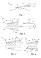
- a sample 16 to be heated by microwave radiation is arranged.
- the general direction of propagation of the microwave radiation inside the applicator 10 is essentially parallel to the interface 15 as depicted by arrow 17, a part of the microwave radiation will be transmitted perpendicularly to the overall direction of propagation 17 through the interface 15 into the sample 16.
- sample 16 is heated.
- the interface 15 is essentially a rectangular planar surface which can be placed directly on the sample to be heated. Due to the tapering of the transmission duct 13, the energy density transmitted into the sample per unit area of the interface 15 will be essentially constant along the direction of propagation 17.
- FIG. 2 shows a further embodiment of the microwave applicator 20 of the invention. Elements of the embodiment of Figure 2 which correspond to elements of the embodiment of Figure 1 or which have a similar function are denoted by the same reference numerals but increased by 10 and will not be described in detail again.
- the applicator 20 comprises a cavity 28 in which the sample 26 to be heated is arranged.
- the cavity 28 is essentially defined by the partially microwave-permeable interface 25 of the tapering section 23 of the applicator 20.
- Cavity 28 has an overall cylindrical form having a longitudinal axis 29.
- the interface 25 is essentially arranged parallel to the longitudinal axis 29 of the sample surrounding the longitudinal axis 29 in order to define a cylindrical jacket surrounding the cavity.
- the geometrical arrangement of the tapering section 23 circumferentially surrounding the longitudinal central axis 29 of cavity 28 is depicted schematically. Consequently, microwave radiation 22 can penetrate from all sides through jacket-like interface 25 into sample 26.
- the microwave applicator 30 comprises a source of microwave energy which is constituted by a waveguide 31 for transferring microwave radiation 32 from an external source (not shown in Figure 3 ) to the tapering section 33.
- the embodiments of Figures 6 and 7 show variants of the embodiment of Figure 5 where the source of microwave radiation is either waveguide 61 provided with the apparatus 60 of Figure 6 or an antenna 71 of a microwave generator arranged within the tapering section 73 of the microwave apparatus 70 of the embodiment of Figure 7 .
- Figure 8 schematically depicts a cross-sectional view parallel to the longitudinal axis of a cylindrical cavity of a microwave-heating apparatus which comprises two microwave applicators 60, 60', each essentially corresponding to the microwave applicator 60 of Figure 6 .
- the applicators 60, 60' are stacked upon each other in the longitudinal direction of the central longitudinal axis 69 of cavity 68 in order to provide a larger overall interface 65 for transmitting microwave radiation 62, 62' into the sample 66.
- the cavity 68 is arranged as a conduit capable of transporting sample 66 in a continuous manner through the microwave treatment area defined by the jacket-like interfaces 65 respectively.
- Figure 9 essentially corresponds to the embodiment of Figure 8 except that the cavity 68' defined by a vessel-like interface 65' is conceived as a cylindrical recess adapted to accommodate a suitable vessel for batch treatment of sample 66'.
- a lid 68a may be provided to protect sample 66' from contamination or to ensure that pressurised heating is possible.
- Conduits 66a, 66b are schematically shown as examples of means to access the internal cavity 68'. Such means may comprise conduits to supply and discharge samples or reactants.
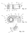
- Figures 10 to 11b show a variant of the microwave applicator of Figure 6 in more detail according to a cross-sectional view parallel to the longitudinal axis 69 of cavity 68 ( Figure 10 ) and perpendicular to the longitudinal axis 69 of cavity 68 ( Figure 11a ).
- Elements of the embodiment of Figures 10 to 11b which correspond to elements of the embodiment of Figure 6 or which have a similar function are denoted by the same reference numerals and will not be described in detail again.
- the source of microwave energy 61 comprises a magnetron 61 a, arranged outside of waveguide 61 b.
- FIG 11 b shows a portion of the tapering section of transmission duct 63 in more detail.
- transmission duct 63 is externally delimited by a metallic wall 63c and internally delimited by a partially microwave-transparent interface 65 which consists of several layers 65a, 65b and 65c.
- the internal volume defined by external wall 63c and interface 65 is filled with the dielectric material 63a through which microwave radiation generated by microwave source 61 can propagate.
- the interface 65 can be constituted by several functional layers which can be designed in accordance with any particular requirements of a particular application.
- layer 65a can be made of a ceramic material which ensures enough structural strength of the interface 65 in order to withstand high pressures within a cavity 68.
- Layer 65b can be provided with means to control the temperature of the sample housed in cavity 68 and layer 65c can, for instance, be a thin, chemically inert liner, e.g. made from PTFE.
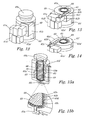
- Figures 12 to 15b depict various views of a further variant of the embodiment of Figure 9 .
- Elements of the embodiment of Figures 12 to 15b which correspond to elements of the embodiment of Figure 9 or which have a similar function are denoted by the same reference numerals and will not be described in detail again.
- Figure 12 depicts an embodiment of the microwave-heating apparatus of the invention in which two microwave applicators such as the applicator of Figure 11a are stacked upon each other along the central vertical axis of an essentially cylindrical cavity containing the sample 66 to be treated.
- the heating apparatus of Figure 12 comprises two microwave applicators similar to the applicator described in connection with Figure 11a .
- cooling channels 65d are arranged in the functional layer 65b of interface 65.
- a cooling liquid having low microwave absorbance is fed to the apparatus via entry manifold 65e and circulated through the cooling channels 65d to leave the apparatus via exit manifold 65f.
- Entry manifold 65e, cooling channels 65d and exit channels 65f can be part of a closed cooling circuit (not shown in the drawings) which may, for instance, comprise a heat exchanger (also not shown).
Priority Applications (2)
| Application Number | Priority Date | Filing Date | Title |
|---|---|---|---|
| EP08150982A EP2086285A1 (de) | 2008-02-01 | 2008-02-01 | Applikator und Vorrichtung zur Erwärmung von Proben durch Mikrowellenstrahlung |
| US12/361,888 US8969768B2 (en) | 2008-02-01 | 2009-01-29 | Applicator and apparatus for heating samples by microwave radiation |
Applications Claiming Priority (1)
| Application Number | Priority Date | Filing Date | Title |
|---|---|---|---|
| EP08150982A EP2086285A1 (de) | 2008-02-01 | 2008-02-01 | Applikator und Vorrichtung zur Erwärmung von Proben durch Mikrowellenstrahlung |
Publications (1)
| Publication Number | Publication Date |
|---|---|
| EP2086285A1 true EP2086285A1 (de) | 2009-08-05 |
Family
ID=39500041
Family Applications (1)
| Application Number | Title | Priority Date | Filing Date |
|---|---|---|---|
| EP08150982A Withdrawn EP2086285A1 (de) | 2008-02-01 | 2008-02-01 | Applikator und Vorrichtung zur Erwärmung von Proben durch Mikrowellenstrahlung |
Country Status (2)
| Country | Link |
|---|---|
| US (1) | US8969768B2 (de) |
| EP (1) | EP2086285A1 (de) |
Cited By (2)
| Publication number | Priority date | Publication date | Assignee | Title |
|---|---|---|---|---|
| US8319161B2 (en) | 2009-04-24 | 2012-11-27 | Anton Paar Gmbh | Method and device for uniformly heating a sample by microwave radiation |
| CN111149428A (zh) * | 2017-11-28 | 2020-05-12 | 国立研究开发法人产业技术综合研究所 | 微波处理装置、微波处理方法以及化学反应方法 |
Families Citing this family (13)
| Publication number | Priority date | Publication date | Assignee | Title |
|---|---|---|---|---|
| IT1401134B1 (it) * | 2010-07-19 | 2013-07-12 | Geolog Spa | Sistema e metodo per il condizionamento termico di un fluido in particolare un fango di perforazione |
| CN110072607A (zh) | 2016-10-06 | 2019-07-30 | 利腾股份有限公司 | 具有气固分离的微波反应器系统 |
| US9812295B1 (en) | 2016-11-15 | 2017-11-07 | Lyten, Inc. | Microwave chemical processing |
| US9767992B1 (en) | 2017-02-09 | 2017-09-19 | Lyten, Inc. | Microwave chemical processing reactor |
| US9997334B1 (en) | 2017-02-09 | 2018-06-12 | Lyten, Inc. | Seedless particles with carbon allotropes |
| CN110418816B (zh) | 2017-03-16 | 2022-05-31 | 利腾股份有限公司 | 碳和弹性体整合 |
| US10920035B2 (en) | 2017-03-16 | 2021-02-16 | Lyten, Inc. | Tuning deformation hysteresis in tires using graphene |
| US9862606B1 (en) | 2017-03-27 | 2018-01-09 | Lyten, Inc. | Carbon allotropes |
| EP3393204B1 (de) * | 2017-04-18 | 2021-11-10 | Anton Paar GmbH | Mikrowellengerät |
| US10465128B2 (en) | 2017-09-20 | 2019-11-05 | Lyten, Inc. | Cracking of a process gas |
| WO2019126196A1 (en) | 2017-12-22 | 2019-06-27 | Lyten, Inc. | Structured composite materials |
| WO2019143559A1 (en) | 2018-01-16 | 2019-07-25 | Lyten, Inc. | Microwave transparent pressure barrier |
| US11421547B2 (en) * | 2020-01-06 | 2022-08-23 | Rohr, Inc. | Thermal-anti-icing system with microwave system |
Citations (19)
| Publication number | Priority date | Publication date | Assignee | Title |
|---|---|---|---|---|
| US2560536A (en) * | 1948-03-23 | 1951-07-17 | Charles F Althouse | High-frequency power measuring device, including a water load |
| US3312914A (en) * | 1965-04-29 | 1967-04-04 | Gen Electric | High power microwave load |
| US3474209A (en) * | 1967-04-10 | 1969-10-21 | Rca Corp | Dielectric heating |
| US3555232A (en) * | 1968-10-21 | 1971-01-12 | Canadian Patents Dev | Waveguides |
| US3848106A (en) | 1972-05-29 | 1974-11-12 | Stiftelsen Inst Mikrovags | Apparatus for heating by microwave energy |
| US4067683A (en) * | 1976-06-14 | 1978-01-10 | Frank T. Sullivan, Inc. | Method and apparatus for controlling fluency of high viscosity hydrocarbon fluids |
| US4740763A (en) * | 1986-04-14 | 1988-04-26 | Max-Planck-Gesellschaft Zur Foerderung Der Wissenschaften E.V. | Microwave calorimeter |
| GB2206470A (en) | 1987-06-26 | 1989-01-05 | Emi Plc Thorn | Cooker appliances |
| WO1990004910A1 (en) * | 1988-10-25 | 1990-05-03 | Industrial Microwave Applications Pty. Limited | Microwave pipe warmer |
| US5186540A (en) * | 1991-12-30 | 1993-02-16 | Raytheon Company | Power measurement calorimeter |
| US5523548A (en) * | 1994-01-31 | 1996-06-04 | Nec Corporation | Electromagnetic wave heater having a cone-shaped container whose tapered portion is pointed and directed toward the electromagnetic wave generator |
| US6294772B1 (en) | 1998-09-04 | 2001-09-25 | Cem Corporation | Microwave probe applicator for physical and chemical processes |
| US20010035407A1 (en) * | 1999-04-28 | 2001-11-01 | Drozd J. Michael | Electromagnetic exposure chamber with a focal region |
| EP1228801A1 (de) * | 1999-03-01 | 2002-08-07 | CEM Corporation | Druckbehälter mit Hülle aus zusammengesetztem Material |
| US20030102306A1 (en) * | 2001-11-09 | 2003-06-05 | Risman Per Olov G. | Microwave applicator system |
| WO2003048409A1 (en) * | 2001-11-30 | 2003-06-12 | Corning Incorporated | Apparatus for depositing a plasma chemical vapor deposition coating on the inside of an optical fiber preform |
| US6579501B1 (en) * | 1997-01-09 | 2003-06-17 | Berthold Gmbh And Co. Kg | Apparatus for carrying out wet chemical reactions under pressure |
| GB2387544A (en) * | 2002-10-10 | 2003-10-22 | Microsulis Plc | Microwave Applicator |
| WO2005043953A2 (en) * | 2003-10-24 | 2005-05-12 | The Ferrite Company, Inc. | Choke assembly for continuous conveyor microwave oven |
Family Cites Families (11)
| Publication number | Priority date | Publication date | Assignee | Title |
|---|---|---|---|---|
| US470763A (en) * | 1892-03-15 | Island | ||
| US3577207A (en) * | 1969-05-07 | 1971-05-04 | Vladimir Pavlovich Kirjushin | Microwave plasmatron |
| US5364519A (en) | 1984-11-30 | 1994-11-15 | Fujitsu Limited | Microwave plasma processing process and apparatus |
| US4883570A (en) * | 1987-06-08 | 1989-11-28 | Research-Cottrell, Inc. | Apparatus and method for enhanced chemical processing in high pressure and atmospheric plasmas produced by high frequency electromagnetic waves |
| US5030929A (en) * | 1990-01-09 | 1991-07-09 | General Atomics | Compact waveguide converter apparatus |
| US5359177A (en) | 1990-11-14 | 1994-10-25 | Mitsubishi Denki Kabushiki Kaisha | Microwave plasma apparatus for generating a uniform plasma |
| DE19600223A1 (de) * | 1996-01-05 | 1997-07-17 | Ralf Dr Dipl Phys Spitzl | Vorrichtung zur Erzeugung von Plasmen mittels Mikrowellen |
| AU6949898A (en) * | 1997-04-04 | 1998-10-30 | Robert C. Dalton | Artificial dielectric device for heating gases with electromagnetic energy |
| EP1397939B1 (de) * | 2001-06-01 | 2007-12-19 | Communication and Power Industries, Inc. | Mikrowellenapplikator zur erwärmung einer strömenden flüssigkeit |
| KR101148048B1 (ko) * | 2004-05-25 | 2012-05-25 | 파나소닉 주식회사 | 전하 중화 장치 |
| CN101091420B (zh) * | 2005-04-26 | 2011-02-23 | 株式会社岛津制作所 | 表面波激发等离子体产生装置以及表面波激发等离子体处理装置 |
-
2008
- 2008-02-01 EP EP08150982A patent/EP2086285A1/de not_active Withdrawn
-
2009
- 2009-01-29 US US12/361,888 patent/US8969768B2/en not_active Expired - Fee Related
Patent Citations (19)
| Publication number | Priority date | Publication date | Assignee | Title |
|---|---|---|---|---|
| US2560536A (en) * | 1948-03-23 | 1951-07-17 | Charles F Althouse | High-frequency power measuring device, including a water load |
| US3312914A (en) * | 1965-04-29 | 1967-04-04 | Gen Electric | High power microwave load |
| US3474209A (en) * | 1967-04-10 | 1969-10-21 | Rca Corp | Dielectric heating |
| US3555232A (en) * | 1968-10-21 | 1971-01-12 | Canadian Patents Dev | Waveguides |
| US3848106A (en) | 1972-05-29 | 1974-11-12 | Stiftelsen Inst Mikrovags | Apparatus for heating by microwave energy |
| US4067683A (en) * | 1976-06-14 | 1978-01-10 | Frank T. Sullivan, Inc. | Method and apparatus for controlling fluency of high viscosity hydrocarbon fluids |
| US4740763A (en) * | 1986-04-14 | 1988-04-26 | Max-Planck-Gesellschaft Zur Foerderung Der Wissenschaften E.V. | Microwave calorimeter |
| GB2206470A (en) | 1987-06-26 | 1989-01-05 | Emi Plc Thorn | Cooker appliances |
| WO1990004910A1 (en) * | 1988-10-25 | 1990-05-03 | Industrial Microwave Applications Pty. Limited | Microwave pipe warmer |
| US5186540A (en) * | 1991-12-30 | 1993-02-16 | Raytheon Company | Power measurement calorimeter |
| US5523548A (en) * | 1994-01-31 | 1996-06-04 | Nec Corporation | Electromagnetic wave heater having a cone-shaped container whose tapered portion is pointed and directed toward the electromagnetic wave generator |
| US6579501B1 (en) * | 1997-01-09 | 2003-06-17 | Berthold Gmbh And Co. Kg | Apparatus for carrying out wet chemical reactions under pressure |
| US6294772B1 (en) | 1998-09-04 | 2001-09-25 | Cem Corporation | Microwave probe applicator for physical and chemical processes |
| EP1228801A1 (de) * | 1999-03-01 | 2002-08-07 | CEM Corporation | Druckbehälter mit Hülle aus zusammengesetztem Material |
| US20010035407A1 (en) * | 1999-04-28 | 2001-11-01 | Drozd J. Michael | Electromagnetic exposure chamber with a focal region |
| US20030102306A1 (en) * | 2001-11-09 | 2003-06-05 | Risman Per Olov G. | Microwave applicator system |
| WO2003048409A1 (en) * | 2001-11-30 | 2003-06-12 | Corning Incorporated | Apparatus for depositing a plasma chemical vapor deposition coating on the inside of an optical fiber preform |
| GB2387544A (en) * | 2002-10-10 | 2003-10-22 | Microsulis Plc | Microwave Applicator |
| WO2005043953A2 (en) * | 2003-10-24 | 2005-05-12 | The Ferrite Company, Inc. | Choke assembly for continuous conveyor microwave oven |
Cited By (4)
| Publication number | Priority date | Publication date | Assignee | Title |
|---|---|---|---|---|
| US8319161B2 (en) | 2009-04-24 | 2012-11-27 | Anton Paar Gmbh | Method and device for uniformly heating a sample by microwave radiation |
| CN111149428A (zh) * | 2017-11-28 | 2020-05-12 | 国立研究开发法人产业技术综合研究所 | 微波处理装置、微波处理方法以及化学反应方法 |
| JPWO2019107402A1 (ja) * | 2017-11-28 | 2020-11-19 | 国立研究開発法人産業技術総合研究所 | マイクロ波処理装置、マイクロ波処理方法及び化学反応方法 |
| EP3720248A4 (de) * | 2017-11-28 | 2021-08-25 | National Institute Of Advanced Industrial Science | Mikrowellenbehandlungsvorrichtung, mikrowellenbehandlungsverfahren und chemisches reaktionsverfahren |
Also Published As
| Publication number | Publication date |
|---|---|
| US8969768B2 (en) | 2015-03-03 |
| US20090194528A1 (en) | 2009-08-06 |
Similar Documents
| Publication | Publication Date | Title |
|---|---|---|
| EP2086285A1 (de) | Applikator und Vorrichtung zur Erwärmung von Proben durch Mikrowellenstrahlung | |
| JP3717403B2 (ja) | 核燃料のマイクロ波焼結方法及び装置 | |
| US10281482B2 (en) | Non-modal interplate microwave heating system and method of heating | |
| EP2244529B1 (de) | Vorrichtung zur Erwärmung einer Probe mittels Mikrowellenstrahlung | |
| US6294772B1 (en) | Microwave probe applicator for physical and chemical processes | |
| EP2219415B1 (de) | Mikrowellenerwärmungsvorrichtung und Erwärmungsverfahren | |
| EP1839741B1 (de) | Vorrichtung für chemische reaktionen unter verwendung von mikrowellen | |
| JP2006272055A (ja) | マイクロ波化学反応装置 | |
| EP2395814A2 (de) | Mikrowellenheizvorrichtung | |
| US8759074B2 (en) | Device for applying electromagnetic energy to a reactive medium | |
| US20090074631A1 (en) | Microwave Chemical Reactor | |
| CA2463878C (en) | Microwave heating apparatus | |
| US8759726B2 (en) | Dynamic power splitter | |
| GB2536485A (en) | Scalable reactor for microwave-and ultrasound-assisted chemistry | |
| EP3987889B1 (de) | Elektromagnetischer heizreaktor | |
| KR101298737B1 (ko) | 마이크로파를 이용한 시료 가열장치용 반응기 및 시료 가열 방법 |
Legal Events
| Date | Code | Title | Description |
|---|---|---|---|
| PUAI | Public reference made under article 153(3) epc to a published international application that has entered the european phase |
Free format text: ORIGINAL CODE: 0009012 |
|
| AK | Designated contracting states |
Kind code of ref document: A1 Designated state(s): AT BE BG CH CY CZ DE DK EE ES FI FR GB GR HR HU IE IS IT LI LT LU LV MC MT NL NO PL PT RO SE SI SK TR |
|
| AX | Request for extension of the european patent |
Extension state: AL BA MK RS |
|
| 17P | Request for examination filed |
Effective date: 20091007 |
|
| 17Q | First examination report despatched |
Effective date: 20091120 |
|
| AKX | Designation fees paid |
Designated state(s): AT BE BG CH CY CZ DE DK EE ES FI FR GB GR HR HU IE IS IT LI LT LU LV MC MT NL NO PL PT RO SE SI SK TR |
|
| STAA | Information on the status of an ep patent application or granted ep patent |
Free format text: STATUS: EXAMINATION IS IN PROGRESS |
|
| STAA | Information on the status of an ep patent application or granted ep patent |
Free format text: STATUS: THE APPLICATION IS DEEMED TO BE WITHDRAWN |
|
| 18D | Application deemed to be withdrawn |
Effective date: 20190903 |