EP2086264A1 - Verfahren zur Steuerung des Zugangs eines Endgeräts zu einer Radiokommunikationsnetzwerkinfrastruktur und Zugangspunktkontrollmodul - Google Patents
Verfahren zur Steuerung des Zugangs eines Endgeräts zu einer Radiokommunikationsnetzwerkinfrastruktur und Zugangspunktkontrollmodul Download PDFInfo
- Publication number
- EP2086264A1 EP2086264A1 EP09151884A EP09151884A EP2086264A1 EP 2086264 A1 EP2086264 A1 EP 2086264A1 EP 09151884 A EP09151884 A EP 09151884A EP 09151884 A EP09151884 A EP 09151884A EP 2086264 A1 EP2086264 A1 EP 2086264A1
- Authority
- EP
- European Patent Office
- Prior art keywords
- access
- infrastructure
- access point
- sleep mode
- user equipment
- Prior art date
- Legal status (The legal status is an assumption and is not a legal conclusion. Google has not performed a legal analysis and makes no representation as to the accuracy of the status listed.)
- Withdrawn
Links
Images


Classifications
-
- H—ELECTRICITY
- H04—ELECTRIC COMMUNICATION TECHNIQUE
- H04W—WIRELESS COMMUNICATION NETWORKS
- H04W48/00—Access restriction; Network selection; Access point selection
- H04W48/16—Discovering, processing access restriction or access information
-
- H—ELECTRICITY
- H04—ELECTRIC COMMUNICATION TECHNIQUE
- H04W—WIRELESS COMMUNICATION NETWORKS
- H04W48/00—Access restriction; Network selection; Access point selection
- H04W48/08—Access restriction or access information delivery, e.g. discovery data delivery
- H04W48/14—Access restriction or access information delivery, e.g. discovery data delivery using user query or user detection
-
- H—ELECTRICITY
- H04—ELECTRIC COMMUNICATION TECHNIQUE
- H04W—WIRELESS COMMUNICATION NETWORKS
- H04W52/00—Power management, e.g. TPC [Transmission Power Control], power saving or power classes
- H04W52/02—Power saving arrangements
- H04W52/0203—Power saving arrangements in the radio access network or backbone network of wireless communication networks
- H04W52/0206—Power saving arrangements in the radio access network or backbone network of wireless communication networks in access points, e.g. base stations
-
- H—ELECTRICITY
- H04—ELECTRIC COMMUNICATION TECHNIQUE
- H04W—WIRELESS COMMUNICATION NETWORKS
- H04W92/00—Interfaces specially adapted for wireless communication networks
- H04W92/16—Interfaces between hierarchically similar devices
- H04W92/20—Interfaces between hierarchically similar devices between access points
-
- Y—GENERAL TAGGING OF NEW TECHNOLOGICAL DEVELOPMENTS; GENERAL TAGGING OF CROSS-SECTIONAL TECHNOLOGIES SPANNING OVER SEVERAL SECTIONS OF THE IPC; TECHNICAL SUBJECTS COVERED BY FORMER USPC CROSS-REFERENCE ART COLLECTIONS [XRACs] AND DIGESTS
- Y02—TECHNOLOGIES OR APPLICATIONS FOR MITIGATION OR ADAPTATION AGAINST CLIMATE CHANGE
- Y02D—CLIMATE CHANGE MITIGATION TECHNOLOGIES IN INFORMATION AND COMMUNICATION TECHNOLOGIES [ICT], I.E. INFORMATION AND COMMUNICATION TECHNOLOGIES AIMING AT THE REDUCTION OF THEIR OWN ENERGY USE
- Y02D30/00—Reducing energy consumption in communication networks
- Y02D30/70—Reducing energy consumption in communication networks in wireless communication networks
Definitions
- the present invention relates to a method for managing the access of a user equipment to a radio network infrastructure, as well as to an access point of the infrastructure, and to a user equipment, for the implementation of process.
- the invention relates to any type of radio communication network with mobiles, and in particular second generation cellular networks (GSM, GPRS, IS-95), third generation networks (UMTS, CDMA2000) or their evolutions (LTE). It also concerns wireless local area networks, WLAN ("Wireless Local Area Network” - IEEE 802.11a, Wi-Fi (802.11g), ETSI HiperLAN / 2), and WiMAX (IEEE 802.16, ETSI HiperMAM).
- the access of a user equipment to a radio network infrastructure is carried out according to a defined random access procedure in which a user equipment seeking for example to initiate a communication sends to an access point a random access request.
- the radio network infrastructure typically comprises a set of base stations, base station routers, access points, or other equipment arranged to communicate with user equipment on the air interface.
- Cellular telephones, PDAs, GPS equipment, pagers, mobile phones, laptops equipped with WiFi or WiMAX connection means are examples of user equipment.
- the establishment of a connection between the user equipment and the radio network infrastructure is made as soon as the access request is served by the network.
- the access procedure typically involves system information, which is broadcast to the equipment under the radio coverage of the infrastructure access points. Access to these System information generally requires that the user equipment has previously synchronized to a beacon signal broadcast by each access point of the infrastructure.
- UMTS which is a third-generation radio communication system whose access network, called UMTS Terrestrial Radio Access Network (UTRAN), uses code division multiple access (CDMA).
- CDMA code division multiple access
- “Code-Division Multiple Access” that is to say that the symbols transmitted are multiplied by spreading codes consisting of samples called “chips” whose rate (3.84 Mchip / s in the case of The UMTS) is greater than that of the transmitted symbols.
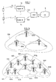
- the figure 1 illustrates an example of a UMTS network architecture.
- the UTRAN access network comprises radio network controllers 5 called RNC ("Radio Network Controller") which, via a lub interface, drive network nodes 1a, 1b called “Node B", each node. B has one or more base stations each serving one or more cells. These base stations communicate by radio with 2.3 mobile terminals called UE ("User Equipment") via a Uu interface (see technical specification 3GTS25.401, version 3.3.0, published by the 3GPP organization ).
- the UTRAN is connected to a core network 6 (CN, "Core Network”), by means of a so-called read interface.
- CN core network 6
- the spreading codes distinguish different PhCH physical channels which are superimposed on the same transmission resource constituted by a carrier frequency.
- the auto- and inter-correlation properties of the spreading codes allow the receiver to separate the PhCHs and to extract the symbols intended for them.
- a scrambling code is allocated to each base station, and different physical channels used by that base station are distinguished by mutually orthogonal channelization codes.
- the global spreading code is the product of the "channelisation” code and the "scrambling" code of the base station.
- the spreading factor (equal to the ratio of the rate of the chips and the rate of the symbols ) is a power of 2 between 4 and 512. This factor is chosen according to the symbol rate to be transmitted on the PhCH.
- Each base station cell broadcasts on the radio coverage a beacon signal on a primary pilot channel called CPICH.
- the beacon signal comprises a predefined bit sequence, and is described in section 5.3.3 of Technical Specification TS 25.211 ("Universal Mobile Telecommunications System (UMTS)"). ). version 3.9.0, published by 3GPP in December 2001.
- Each UE 2, 3 can be in several UTHAN link states, managed by a Radio Resource Control (RRC) protocol implemented at the RNC level and at the EU level (see technical specification 3G TS 25.331, version 3.3.0, published June 2000 by 3GPP, section 9), including a standby state or other states where the UE is actively connected to the network.
- RRC Radio Resource Control
- the UE When the UE is powered on and in a selected cell without having any communication in progress with the UTRAN, it is in a sleep state ("idle").
- the initial selection and cell reselection processes are described in the technical specification 3G TS 25.304, version 3.6.0 published in March 2001 by the 3GPP, section 5.2,
- the UE receives system information transmitted on a broadcast channel (BCH) by the base station of the selected cell (see Technical Specification 3G TS 25.331, version 3.9.0 published in December 2001 by 3GPP, section 8.1.1).
- This system information includes, among other things, upstream access control information, as well as information relating to the random access procedure on the physical layer.
- the UE transmits to the selected base station a random access request signal on a common channel called PRACH (Physical Random Access Channel).
- PRACH Physical Random Access Channel
- This random access procedure is performed by the physical layer (see technical specifications 3G TS 25.211 and TS 25.214, version 3.9.0, section 6) under the control of the access control layer. medium (MAC, see technical specification 3G TS 25.321, version 3.9.0, published in September 2001 by 3GPP, section 11.2) and the RRC layer.
- a random access procedure is also provided in the fourth generation LTE ("Long Term Evolution”) type systems.
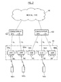
- the figure 2 illustrates an example architecture of an LTE network.
- the switches of the mobile service 100 belonging to a core network (EPC, "Evolved Packet Core”), are connected on one hand to one or more fixed networks 110 and on the other hand, by means of an interface called S1, to 120a-120e base stations, or eNB or eNodeB.
- the 120a-120e base stations distributed over the coverage territory of the network, communicate with each other by means of an interface known as X2 and are able to communicate by radio with the mobile terminals 140, 140a, 140b, also called UEs (" User Equipment ").
- a Node-B and an RNC in the architecture of a UMTS access network have been integrated within the LTE 120a-120e base station.
- the base stations 120a-120e can further each serve one or more cells by means of respective transceivers 130. They form an access network called E-UTRAN 131 ("Evolved UTRAN").
- E-UTRAN 131 Evolved UTRAN
- Various physical channels are also defined for the LTE system, as well as physical reference and synchronization signals.
- the defined physical channels include a system information broadcast channel, the PBCH.
- an UE 140,140a, 140b When an UE 140,140a, 140b is no longer under the radio coverage of E-UTRAN 131, for example due to a lack of coverage, it no longer receives a synchronization signal or system information, however necessary to synchronize with the access network, and can no longer perform the procedure of access to the network.
- an UE may be in a situation where it can synchronize with the access network, process the received system information on the BCCH broadcast channel, and initiate an access request, and random access failed. It is also prevented from initiating a communication without having information or influence on the state of the access network, in particular on the possibility for it to increase its capacity.
- the invention aims to improve this situation.
- the invention thus proposes a method of managing access of a user equipment to an infrastructure of a radio communication network comprising at least one access point, in which, on receipt of an impossibility information signal. access to the infrastructure, a first access point sends to a second access point with which it is able to communicate, said second access point being in a sleep mode in which it emits no signal from synchronization, an exit request message of the sleep mode.
- the information signal for impossibility of access to the infrastructure may have been transmitted by the user equipment following a negative test for the presence of radio coverage of the radio network infrastructure.
- the second access point upon receipt of the sleep mode exit request message, leaves the sleep mode to return to normal operating mode
- the second access point upon receipt of the sleep mode exit request message, modifies the extent of its radio coverage.
- the invention also proposes an access point control module of a radiocommunication infrastructure, arranged to receive an exit request of a sleep mode in which it emits no synchronization signal, coming from another point.
- infrastructure access, or access point controller of the infrastructure or operation and maintenance subsystem node are also proposes an access point control module of a radiocommunication infrastructure, arranged to receive an exit request of a sleep mode in which it emits no synchronization signal, coming from another point.
- This access point control module of a radiocommunication infrastructure may advantageously be implemented within a programmable logic circuit, for example of the FPGA, ASIC or CPLD type, or within a user equipment,
- This control module can also be advantageously integrated within a base station.
- the invention finally proposes a computer program loadable in a memory associated with a processor, and comprising instructions for the implementation of a method as defined above during the execution of said program by the processor, as well as that a computer medium on which is recorded said program.
- some base stations of the radio network infrastructure may be switched to modes of operation different from the nominal mode of operation. They can for example be extinguished for the purpose of maintenance, or switch to a sleep mode in which they no longer provide radio coverage.
- Operation in sleep mode in which the base station stops transmitting, including its broadcast channel carrying system information, may be activated for predetermined periods, for example during the night, or any other time when it is found that radio coverage or traffic requirements are lower than in normal use periods.
- the radio coverage is provided by a set of radio coverage equipment, such as radio transmitting / receiving points, base stations, base station RF heads, or repeaters.
- radio coverage equipment such as radio transmitting / receiving points, base stations, base station RF heads, or repeaters.
- the requirements in terms of coverage and capacity lead to a sharp increase in the number of such equipment in urban environments.
- the cumulative power consumption of all of these radio coverage equipment is high, even though the total traffic over a given radio coverage is often not at the level of the maximum capacity that the network is expected to provide. .
- radio coverage of radio coverage equipment may vary dynamically, depending in particular on the radio environment of the equipment.
- Techniques such as "cell breathing", automatic beacon signal strength control, adaptive tilt control of an antenna system, allow rapid modification of the radio coverage of radio coverage equipment. Therefore, radio coverage can be provided with two levels of radio coverage equipment, one being provided with a capacity corresponding to a low traffic (for example at night), the other being provided with a capacity corresponding to high traffic (eg day)
- This type of radio coverage is glossy at the figure 3 .
- the area 300 over which radio coverage is to be performed is covered by cells generated by a limited number of radio coverage equipment 301a, 301b and 301c.
- This first configuration corresponds to a coverage of zone 300 with a weak capacity, intended to be implemented at times when traffic in zone 300 is low.
- the area 300 is covered by smaller cells, generated by a larger number of radio coverage equipment 302a-302j.
- This second configuration corresponds to a coverage of the zone 300 with a high capacity, intended to be implemented at times when the traffic in zone 300 is important.
- the transition from the second configuration to the first configuration may be effected, not by simply turning off the radio coverage equipment 302a-302j of the second configuration, but by placing them in sleep mode, while the radio coverage equipment 301a - 301c of the first configuration are placed in normal operating mode (and not in sleep mode).
- the transition from the first configuration to the second configuration can be performed by placing the radio coverage equipment 301a - 301c of the first configuration in sleep mode, while the radio coverage equipment 302a - 302j are out of the sleep mode to return to a nominal operating mode.
- radio coverage equipment such as a base station
- radio coverage equipment When radio coverage equipment, such as a base station, it stops providing radio coverage without being completely turned off. For this, it can stop transmitting its broadcast channel carrying system information.
- the radio coverage equipment in the sleep mode also ceases to transmit and receive any signal whose taking into account requires the prior reception of the broadcast system information in normal operating mode (such as for example the transmission of a paging message to a user equipment). It can also stop broadcasting its beacon signal. Moreover, it activates its means for monitoring the reception of the request to exit the sleep mode.
- Such a request to exit the sleep mode can come from a single source or from several sources from the following different sources: it can be for a base station of a base station controller, as for example on the figure 1 RNC 5 for Node-B 1a, 1b, or well, another example, another base station, for example near the base station in sleep mode, as for example on the figure 2 the eNB 120c for the eNB 120d, or else, another example, a user equipment, such as on the figure 2 the EU 140c for the eNB 120d.
- the base station activates, according to the planned sleep mode output procedures, its means for monitoring the reception of a sleep mode exit request from the controller supervises, its means for monitoring the reception of a request to exit the sleep mode from a neighboring base station, its means for monitoring the reception of a request to exit the sleep mode from a user equipment, or activates a plurality or all of the three aforementioned means.
- the entry and exit of the sleep mode can of course also be controlled from an operation and maintenance (O & M) infrastructure, so that the activation of a given mode of operation for a point d network access is under the control of a network operator.
- O & M operation and maintenance
- the figure 2 allows to illustrate a first aspect of the invention in which a UE seeks to access the network while the access point through which it accesses the network by the random access procedure is in sleep mode.
- a UE seeks to access the network while the access point through which it accesses the network by the random access procedure is in sleep mode.
- it may be eNB 120d.
- the eNB 120d goes into sleep mode, it stops transmitting its synchronization signal.
- UE 140c which, when the eNB 120d is not in sleep mode, would be under its radio coverage, is also not under the radio coverage of eN8 neighbors 120c, 120e of eNB 102d so that it receives no signal enabling it to synchronize on the E-UTRAN network 131 to which the eNB 120d belongs. It therefore no longer has access to the E-UTRAN infrastructure from information carried by a PBCH channel broadcast by an access point 120a - 120e of this network E-UTRAN 131.
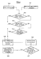
- the figure 4 illustrates an example of a radio coverage presence test procedure.
- the UE 140e performs a radio coverage presence test under different circumstances, for example when it loses synchronization with the E-UTRAN network 131 (step 500), or after being powered on (501).
- This E-UTRAN radio coverage presence test comprises a first test of reception of a beacon signal (step 502) of type conforming to the LTE specifications.
- the radio coverage presence test is declared negative (step 505).
- the radio coverage presence test comprises a set of tests that must be successively declared positive for the radio coverage test to be.
- the radio coverage presence test comprises a set of tests that must be successively declared positive for the radio coverage test to be.
- the radio coverage presence test continues with a random access procedure success test (step 504).
- this random access procedure success test step 504 is negative, the radio coverage presence test is declared negative (step 505).
- a radio coverage presence test procedure comprising only a beacon signal reception test. It is also possible to provide, in another embodiment, a radio coverage presence test procedure comprising only a reception test of the system information. It is still possible to provide, in another embodiment, a radio coverage presence test procedure comprising only the beacon signal reception and the reception of the system information, the two tests being carried out successively as described. previously.
- the access infrastructure access test result does not systematically trigger the transmission of an information signal of impossibility of access to the infrastructure. It is first made known to the user of the user equipment (step 506) by any means known per se (signal on graphic user interface (GUI), audible signal, visual signal , etc.). The user can then request the transmission of an information signal of impossibility of access to the infrastructure (step 507), either expressly or implicitly by means of another command, such as for example a command emergency call. It is also possible to envisage, without departing from the scope of the present invention, configurable user equipment that can be configured to operate according to the first or the second of the two aforementioned modes.
- GUI graphic user interface
- This information signal of impossibility of access to the infrastructure is potentially received by any eNB it can reach by its scope, and its function is to alert the eNBs that receive it, in order to cause the exit of the sleep mode of at least some of these eNBs, following the expected sleep mode exit procedures.
- the information signal for impossibility of access to the infrastructure transmitted by the UE 140c is received by the eNB 120d which decodes it and interprets it as an exit request of the sleep mode. It thus triggers the exit of the sleep mode to the eNB 120d, that is to say the resumption of transmission and reception of all the signals which it had ceased to transmit or receive when it was in mode sleep, to return to normal operating mode.
- the eNB 120d will resume the broadcast of the beacon signal, and system information, from which the UE 140c can initiate a random access procedure to the e-UTRAN 131 via the e-NB access point 120d.
- the information signal format of impossibility of access to the infrastructure must allow the base station that receives it in sleep mode to detect and demodulate it. It is possible to use a phase-locked radio receiver in the base station.
- different physical formats are suitable for the information signal of impossibility of access to the infrastructure, which have the advantage of not requiring prior synchronization between the base station and the user equipment.
- the signal may be modulated according to an On-Key Keying (OOK), such as an OOK-type amplitude modulation or a two-state phase modulation.
- OOK On-Key Keying
- This signal format is then particularly simple, the information of impossibility of access to the infrastructure leading in certain cases to leave an access point of the sleep mode to return to normal operating mode being carried by the type of modulation chosen.
- a base station of the information signal of impossibility of access to the infrastructure in order to increase the capacity of reception by a base station of the information signal of impossibility of access to the infrastructure, one can choose to use a more robust modulation than the normal synchronization signal transmitted by base stations.
- This can be achieved by two complementary methods: on the one hand, by an appropriate choice of modulation (for example, two-state modulation with a long bit time in OOK modulation), and on the other hand by the use of a cana coding ! redundant (self-correcting codes).
- the spatial coverage of reception of the signal by the base stations is then greater than the coverage offered by the normal communication between the user equipment and the base stations.
- the figure 5 presents an example of a user equipment functional architecture 406 to which the invention can be applied.
- Cellular telephones, PDAs, GPS equipment, pagers, mobile phones, laptops equipped with WiFi or WiMAX connection means are examples of user equipment.
- the RRC module 403 processes the decoded system information on the BCCH by the reception part 401 of the UE from the radio signal picked up by the antenna 407 and processed by the radio stage 400.
- the receiver module 401 further comprises means for performing, on request of the controller 404, a synchronization signal reception test, and the RRC module 403 means for performing, still on request of the controller 404, a system information reception test.
- the results of these tests are transmitted to the controller 404, which supervises the execution of the radio coverage presence test algorithm and, if necessary, the transmission of an information signal of impossibility of access to infrastructure.
- the transmitter module 402 generates the information signal for impossibility of access to the infrastructure, which is processed by the radio stage before being transmitted by the antenna 407.
- the controller 404 is furthermore arranged to supervise the execution of the random access procedure by the UE 406. It may furthermore be arranged, in accordance with a particular embodiment of the invention, to integrate a negative random access procedure result in a test algorithm. radio coverage presence, to also infer from a random procedure failure a radio coverage negative presence test result.
- the controller 404 also supervises, when the information signal of impossibility of access to the infrastructure is not systematically acknowledged, the information of the user according to the means provided when the radio coverage presence test is carried out. 'proves negative. To do this, it transmits the result of the radio coverage presence test to the human-machine interface module 405.
- the human-machine interface module generates a signal (for example a visual or auditory signal) and stands waiting for a user request. sending the information signal. When this request is detected by the human-machine interface module 405, it is transmitted to the controller 404 which transmits the corresponding instruction to the transmitter module 402.
- the transmitter module 402 generates the information signal of impossibility of access to the infrastructure, which is processed by the radio stage before being transmitted by the antenna 407.
- the figure 6 presents an example of a base station functional architecture 500 to which the invention can be applied.
- the receiver module 503 includes a wake-up signal receiver 504 which is able to detect the reception an information signal of impossibility of access to the infrastructure from a corresponding radio signal picked up on the antenna 501 and processed by the radio stage 502.
- This alarm signal receiver is active when the base station 500 is in sleep mode, that is to say, it performs, frequently if not continuously, a signal detection cycle of information impossibility of access to infrastructure.
- the receiver module transmits the detection information to the controller 505.
- the receiver module is furthermore arranged to decode the information signal of impossibility of access to the received infrastructure if it has been encoded according to an error correction code, it then comprises a decoding module corresponding to the error correction encoding scheme used for the encoding of the signal of information of impossibility of access to the infrastructure.
- the controller 505 is arranged to, if the base station 500 is in sleep mode, then terminate the sleep mode to return to the nominal operating mode.
- the X2 interface communication unit 507 is arranged to receive and process sleep mode output request messages as well as sleep mode input request messages from a base station adjacent to the base station 500. These requests are transmitted to the controller 505 which is arranged to put the base station in sleep mode or in nominal operating mode.
- the invention is not limited to the embodiments of base station, user equipment and access management method described above, only by way of example, but it encompasses all variants that may be considered by the man of art within the scope of the claims below.
Landscapes
- Engineering & Computer Science (AREA)
- Computer Security & Cryptography (AREA)
- Computer Networks & Wireless Communication (AREA)
- Signal Processing (AREA)
- Mobile Radio Communication Systems (AREA)
Applications Claiming Priority (1)
| Application Number | Priority Date | Filing Date | Title |
|---|---|---|---|
| FR0850647A FR2927213A1 (fr) | 2008-02-01 | 2008-02-01 | Procede pour gerer l'acces d'un equipement utilisateur a une infrastructure de reseau de radiocommunication, point d'acces de l'infrastructure, et equipement utilisateur, pour la mise en oeuvre du procede. |
Publications (1)
| Publication Number | Publication Date |
|---|---|
| EP2086264A1 true EP2086264A1 (de) | 2009-08-05 |
Family
ID=39734172
Family Applications (1)
| Application Number | Title | Priority Date | Filing Date |
|---|---|---|---|
| EP09151884A Withdrawn EP2086264A1 (de) | 2008-02-01 | 2009-02-02 | Verfahren zur Steuerung des Zugangs eines Endgeräts zu einer Radiokommunikationsnetzwerkinfrastruktur und Zugangspunktkontrollmodul |
Country Status (2)
| Country | Link |
|---|---|
| EP (1) | EP2086264A1 (de) |
| FR (1) | FR2927213A1 (de) |
Cited By (2)
| Publication number | Priority date | Publication date | Assignee | Title |
|---|---|---|---|---|
| WO2011094081A1 (en) * | 2010-01-29 | 2011-08-04 | Alcatel-Lucent Usa Inc. | Method of controlling a small cell base station |
| WO2015023896A3 (en) * | 2013-08-14 | 2015-05-21 | Qualcomm Incorporated | Detecting and minimizing coverage holes in a communication network |
Citations (4)
| Publication number | Priority date | Publication date | Assignee | Title |
|---|---|---|---|---|
| US6580981B1 (en) * | 2002-04-16 | 2003-06-17 | Meshnetworks, Inc. | System and method for providing wireless telematics store and forward messaging for peer-to-peer and peer-to-peer-to-infrastructure a communication network |
| US20030156558A1 (en) * | 2002-02-01 | 2003-08-21 | International Business Machines Corporation | Extending an allowable transmission distance between a wireless device and an access point by communication with intermediate wireless devices |
| US20060182074A1 (en) * | 1996-06-03 | 2006-08-17 | Kubler Joseph J | Configurable premises based wireless network and operating protocol |
| US20070026818A1 (en) | 2005-07-29 | 2007-02-01 | Willins Bruce A | Signal detection arrangement |
-
2008
- 2008-02-01 FR FR0850647A patent/FR2927213A1/fr not_active Withdrawn
-
2009
- 2009-02-02 EP EP09151884A patent/EP2086264A1/de not_active Withdrawn
Patent Citations (4)
| Publication number | Priority date | Publication date | Assignee | Title |
|---|---|---|---|---|
| US20060182074A1 (en) * | 1996-06-03 | 2006-08-17 | Kubler Joseph J | Configurable premises based wireless network and operating protocol |
| US20030156558A1 (en) * | 2002-02-01 | 2003-08-21 | International Business Machines Corporation | Extending an allowable transmission distance between a wireless device and an access point by communication with intermediate wireless devices |
| US6580981B1 (en) * | 2002-04-16 | 2003-06-17 | Meshnetworks, Inc. | System and method for providing wireless telematics store and forward messaging for peer-to-peer and peer-to-peer-to-infrastructure a communication network |
| US20070026818A1 (en) | 2005-07-29 | 2007-02-01 | Willins Bruce A | Signal detection arrangement |
Non-Patent Citations (1)
| Title |
|---|
| NATHANIEL J AUGUST ET AL: "Enabling Distributed Medium Access Control for Impulse-Based Ultrawideband Radios", IEEE TRANSACTIONS ON VEHICULAR TECHNOLOGY, IEEE SERVICE CENTER, PISCATAWAY, NJ, US, vol. 56, no. 3, 1 May 2007 (2007-05-01), pages 1064 - 1075, XP011181342, ISSN: 0018-9545 * |
Cited By (5)
| Publication number | Priority date | Publication date | Assignee | Title |
|---|---|---|---|---|
| WO2011094081A1 (en) * | 2010-01-29 | 2011-08-04 | Alcatel-Lucent Usa Inc. | Method of controlling a small cell base station |
| CN102763461A (zh) * | 2010-01-29 | 2012-10-31 | 阿尔卡特朗讯公司 | 控制小型小区基站的方法 |
| US8340723B2 (en) | 2010-01-29 | 2012-12-25 | Alcatel Lucent | Small cell base station, and method of controlling a small cell base station |
| WO2015023896A3 (en) * | 2013-08-14 | 2015-05-21 | Qualcomm Incorporated | Detecting and minimizing coverage holes in a communication network |
| US9401874B2 (en) | 2013-08-14 | 2016-07-26 | Qualcomm Incorporated | Minimizing coverage holes in a communication network |
Also Published As
| Publication number | Publication date |
|---|---|
| FR2927213A1 (fr) | 2009-08-07 |
Similar Documents
| Publication | Publication Date | Title |
|---|---|---|
| US9680219B2 (en) | Antenna switching devices, systems, and methods | |
| EP2386175B1 (de) | Verwaltung von funkverbindungen in einem in einem funkkommunikationssystem | |
| CA2268322A1 (fr) | Procede de transfert d'une communication entre deux relais d'une cellule d'un systeme de radio-communication numerique cellulaire | |
| FR2750560A1 (fr) | Procede permettant le transfert de communications | |
| US8588086B2 (en) | Reverse link data rate indication for satellite-enabled communications systems | |
| WO2018184900A1 (fr) | Procede de communication spatiale pour des services iot et systeme spatial de telecommunications correspondant | |
| EP1464148B1 (de) | Kommunikationsverwaltungsverfahren in einem netzwerk, signal, vorrichtung und empfangsgerät dafür | |
| EP2512201B1 (de) | Sende/empfangsstation und verfahren zur Herstellung eines Telekommunikationsnetzknotens | |
| EP0957653B1 (de) | Mobil-Kommunikationssystem, das ein öffentliches System und mindestens ein privates System aufweist | |
| WO2017068305A1 (fr) | Procédé de réveil d'une station de base, actionneur, station de base et système correspondants | |
| FR2825540A1 (fr) | Procede de controle de puissance d'emission d'un terminal radio mobile, terminal mobile et station de base pour la mise en oeuvre de ce procede | |
| US20060285521A1 (en) | Method, system, apparatus and software product implementing downlink code management for fractional dedicated physical channel in timing conflict situations | |
| EP2086264A1 (de) | Verfahren zur Steuerung des Zugangs eines Endgeräts zu einer Radiokommunikationsnetzwerkinfrastruktur und Zugangspunktkontrollmodul | |
| EP0887950A1 (de) | Basisstation mit Antennendiversity zur Übertragung von unidirektionalen Kanälen und entsprechendes Verfahren | |
| FR2893210A1 (fr) | Procede de configuration des ressources radio dans un reseau de telecommunication mobile | |
| EP1202470B1 (de) | Verfahren und Vorrichtung zur Leistungsregelung eines Mobilfunktelefons | |
| EP3939357A1 (de) | Informationsübertragungsverfahren sowie system und vorrichtungen dafür | |
| EP3672298B1 (de) | Verfahren zur vereingung von zwei systemen, von denen jedes eine private mobilfunknetzinfrastruktur umfasst, entsprechendes computerprogramm und vereinigung von zwei systemen, von denen jedes eine private mobilfunktnetzinfrastruktur umfasst | |
| EP3607800B1 (de) | Drahtloskommunikationssystem mit einem physikalischen kanal für übergreifenden direktzugriff in zeit und raum | |
| EP3324699B1 (de) | Verfahren zur bestimmung einer relais-konfiguration zwischen einem zugangspunkt und endgeräten in einer netzarchitektur | |
| FR3103991A1 (fr) | Procede de transfert intercellulaire et reseau associe | |
| CA2158246A1 (fr) | Reseau de radiocommunications cellulaire multicouche avec cellule sans frequence balise | |
| FR3091437A1 (fr) | Scanner radio embarqué dans une structure mobile d’un système de radiocommunications | |
| EP3675581A1 (de) | Herstellung einer verbindung zum datenaustausch unter ip-protokoll zwischen basisstationen von mobilstrukturen mit unterteilung des frequenzbands in frequenzteilbänder | |
| EP3675546A1 (de) | Funkscanner an bord einer mobilen struktur eines funkkommunikationssystems, und verfahren zu ihrer verwendung |
Legal Events
| Date | Code | Title | Description |
|---|---|---|---|
| PUAI | Public reference made under article 153(3) epc to a published international application that has entered the european phase |
Free format text: ORIGINAL CODE: 0009012 |
|
| AK | Designated contracting states |
Kind code of ref document: A1 Designated state(s): AT BE BG CH CY CZ DE DK EE ES FI FR GB GR HR HU IE IS IT LI LT LU LV MC MK MT NL NO PL PT RO SE SI SK TR |
|
| AX | Request for extension of the european patent |
Extension state: AL BA RS |
|
| 17P | Request for examination filed |
Effective date: 20100205 |
|
| 17Q | First examination report despatched |
Effective date: 20100301 |
|
| AKX | Designation fees paid |
Designated state(s): AT BE BG CH CY CZ DE DK EE ES FI FR GB GR HR HU IE IS IT LI LT LU LV MC MK MT NL NO PL PT RO SE SI SK TR |
|
| RAP1 | Party data changed (applicant data changed or rights of an application transferred) |
Owner name: ALCATEL LUCENT |
|
| 111Z | Information provided on other rights and legal means of execution |
Free format text: AT BE BG CH CY CZ DE DK EE ES FI FR GB GR HR HU IE IS IT LI LT LU LV MC MK MT NL NO PL PT RO SE SI SK TR Effective date: 20130410 |
|
| RAP1 | Party data changed (applicant data changed or rights of an application transferred) |
Owner name: ALCATEL LUCENT |
|
| D11X | Information provided on other rights and legal means of execution (deleted) | ||
| STAA | Information on the status of an ep patent application or granted ep patent |
Free format text: STATUS: THE APPLICATION IS DEEMED TO BE WITHDRAWN |
|
| 18D | Application deemed to be withdrawn |
Effective date: 20160720 |