EP2086233A1 - Digital broadcast receiver - Google Patents
Digital broadcast receiver Download PDFInfo
- Publication number
- EP2086233A1 EP2086233A1 EP07743309A EP07743309A EP2086233A1 EP 2086233 A1 EP2086233 A1 EP 2086233A1 EP 07743309 A EP07743309 A EP 07743309A EP 07743309 A EP07743309 A EP 07743309A EP 2086233 A1 EP2086233 A1 EP 2086233A1
- Authority
- EP
- European Patent Office
- Prior art keywords
- display
- screen
- time
- program
- scheduled recording
- Prior art date
- Legal status (The legal status is an assumption and is not a legal conclusion. Google has not performed a legal analysis and makes no representation as to the accuracy of the status listed.)
- Granted
Links
Images


Classifications
-
- H—ELECTRICITY
- H04—ELECTRIC COMMUNICATION TECHNIQUE
- H04N—PICTORIAL COMMUNICATION, e.g. TELEVISION
- H04N5/00—Details of television systems
- H04N5/44—Receiver circuitry for the reception of television signals according to analogue transmission standards
- H04N5/445—Receiver circuitry for the reception of television signals according to analogue transmission standards for displaying additional information
- H04N5/45—Picture in picture, e.g. displaying simultaneously another television channel in a region of the screen
-
- H—ELECTRICITY
- H04—ELECTRIC COMMUNICATION TECHNIQUE
- H04N—PICTORIAL COMMUNICATION, e.g. TELEVISION
- H04N21/00—Selective content distribution, e.g. interactive television or video on demand [VOD]
- H04N21/40—Client devices specifically adapted for the reception of or interaction with content, e.g. set-top-box [STB]; Operations thereof
- H04N21/43—Processing of content or additional data, e.g. demultiplexing additional data from a digital video stream; Elementary client operations, e.g. monitoring of home network or synchronising decoder's clock; Client middleware
- H04N21/431—Generation of visual interfaces for content selection or interaction; Content or additional data rendering
-
- H—ELECTRICITY
- H04—ELECTRIC COMMUNICATION TECHNIQUE
- H04N—PICTORIAL COMMUNICATION, e.g. TELEVISION
- H04N21/00—Selective content distribution, e.g. interactive television or video on demand [VOD]
- H04N21/40—Client devices specifically adapted for the reception of or interaction with content, e.g. set-top-box [STB]; Operations thereof
- H04N21/41—Structure of client; Structure of client peripherals
- H04N21/4104—Peripherals receiving signals from specially adapted client devices
- H04N21/4135—Peripherals receiving signals from specially adapted client devices external recorder
-
- H—ELECTRICITY
- H04—ELECTRIC COMMUNICATION TECHNIQUE
- H04N—PICTORIAL COMMUNICATION, e.g. TELEVISION
- H04N21/00—Selective content distribution, e.g. interactive television or video on demand [VOD]
- H04N21/40—Client devices specifically adapted for the reception of or interaction with content, e.g. set-top-box [STB]; Operations thereof
- H04N21/41—Structure of client; Structure of client peripherals
- H04N21/422—Input-only peripherals, i.e. input devices connected to specially adapted client devices, e.g. global positioning system [GPS]
- H04N21/42204—User interfaces specially adapted for controlling a client device through a remote control device; Remote control devices therefor
-
- H—ELECTRICITY
- H04—ELECTRIC COMMUNICATION TECHNIQUE
- H04N—PICTORIAL COMMUNICATION, e.g. TELEVISION
- H04N21/00—Selective content distribution, e.g. interactive television or video on demand [VOD]
- H04N21/40—Client devices specifically adapted for the reception of or interaction with content, e.g. set-top-box [STB]; Operations thereof
- H04N21/43—Processing of content or additional data, e.g. demultiplexing additional data from a digital video stream; Elementary client operations, e.g. monitoring of home network or synchronising decoder's clock; Client middleware
- H04N21/431—Generation of visual interfaces for content selection or interaction; Content or additional data rendering
- H04N21/4312—Generation of visual interfaces for content selection or interaction; Content or additional data rendering involving specific graphical features, e.g. screen layout, special fonts or colors, blinking icons, highlights or animations
- H04N21/4316—Generation of visual interfaces for content selection or interaction; Content or additional data rendering involving specific graphical features, e.g. screen layout, special fonts or colors, blinking icons, highlights or animations for displaying supplemental content in a region of the screen, e.g. an advertisement in a separate window
-
- H—ELECTRICITY
- H04—ELECTRIC COMMUNICATION TECHNIQUE
- H04N—PICTORIAL COMMUNICATION, e.g. TELEVISION
- H04N21/00—Selective content distribution, e.g. interactive television or video on demand [VOD]
- H04N21/40—Client devices specifically adapted for the reception of or interaction with content, e.g. set-top-box [STB]; Operations thereof
- H04N21/43—Processing of content or additional data, e.g. demultiplexing additional data from a digital video stream; Elementary client operations, e.g. monitoring of home network or synchronising decoder's clock; Client middleware
- H04N21/433—Content storage operation, e.g. storage operation in response to a pause request, caching operations
- H04N21/4334—Recording operations
-
- H—ELECTRICITY
- H04—ELECTRIC COMMUNICATION TECHNIQUE
- H04N—PICTORIAL COMMUNICATION, e.g. TELEVISION
- H04N21/00—Selective content distribution, e.g. interactive television or video on demand [VOD]
- H04N21/40—Client devices specifically adapted for the reception of or interaction with content, e.g. set-top-box [STB]; Operations thereof
- H04N21/43—Processing of content or additional data, e.g. demultiplexing additional data from a digital video stream; Elementary client operations, e.g. monitoring of home network or synchronising decoder's clock; Client middleware
- H04N21/436—Interfacing a local distribution network, e.g. communicating with another STB or one or more peripheral devices inside the home
- H04N21/43622—Interfacing an external recording device
-
- H—ELECTRICITY
- H04—ELECTRIC COMMUNICATION TECHNIQUE
- H04N—PICTORIAL COMMUNICATION, e.g. TELEVISION
- H04N21/00—Selective content distribution, e.g. interactive television or video on demand [VOD]
- H04N21/40—Client devices specifically adapted for the reception of or interaction with content, e.g. set-top-box [STB]; Operations thereof
- H04N21/43—Processing of content or additional data, e.g. demultiplexing additional data from a digital video stream; Elementary client operations, e.g. monitoring of home network or synchronising decoder's clock; Client middleware
- H04N21/443—OS processes, e.g. booting an STB, implementing a Java virtual machine in an STB or power management in an STB
- H04N21/4438—Window management, e.g. event handling following interaction with the user interface
-
- H—ELECTRICITY
- H04—ELECTRIC COMMUNICATION TECHNIQUE
- H04N—PICTORIAL COMMUNICATION, e.g. TELEVISION
- H04N21/00—Selective content distribution, e.g. interactive television or video on demand [VOD]
- H04N21/40—Client devices specifically adapted for the reception of or interaction with content, e.g. set-top-box [STB]; Operations thereof
- H04N21/47—End-user applications
-
- H—ELECTRICITY
- H04—ELECTRIC COMMUNICATION TECHNIQUE
- H04N—PICTORIAL COMMUNICATION, e.g. TELEVISION
- H04N21/00—Selective content distribution, e.g. interactive television or video on demand [VOD]
- H04N21/40—Client devices specifically adapted for the reception of or interaction with content, e.g. set-top-box [STB]; Operations thereof
- H04N21/47—End-user applications
- H04N21/472—End-user interface for requesting content, additional data or services; End-user interface for interacting with content, e.g. for content reservation or setting reminders, for requesting event notification, for manipulating displayed content
- H04N21/47214—End-user interface for requesting content, additional data or services; End-user interface for interacting with content, e.g. for content reservation or setting reminders, for requesting event notification, for manipulating displayed content for content reservation or setting reminders; for requesting event notification, e.g. of sport results or stock market
Definitions
- the present invention relates to a digital broadcast receiver, and specifically relates to a display control technique related to multi-screen display.
- patent document 1 discloses a technique for display two screens of a TV display screen and an Internet screen and also discloses a technique for smoothly switching these screens.
- An object of the present invention is to provide a display control technique that does not give a sense of discomfort to users even when processing for a scheduled recording is started during multi-screen display being provided.
- An aspect of the present invention provides a broadcast receiver capable of providing multi-screen display on a display unit, characterized by comprising a display control unit that performs display control to make at least one screen in a multi-screen go into non-display at a point of time when the time for starting a scheduled recording approaches during multi-screen display. Consequently, a futile operation, which cannot actually be performed, will not be repeatedly performed for a program for which a scheduled recording is performed.
- the aspect of the present invention is characterized in that the display control unit performs control to expand a remaining program using the non-display area. Consequently, the area of the display unit that has gone into non-display can effectively be used.
- the aspect of the present invention is characterized in that the display control unit displays a message relating to the start of the scheduled recording when the time for starting the scheduled recording approaches. For example, it is possible to let a user know that the aforementioned control is being performed correctly, via a message to inform the user of the start of a scheduled recording.
- the aspect of the present invention is characterized in that display provided by the display unit includes display of information obtained via the Internet, and if there is no remaining program, only the display based on the Internet is made to remain. Display based on the Internet can be provided all the time, and thus is suitable for screen display that remains last.
- the display control unit can perform control to display an identification number for the non-displayed channel on the display unit. Consequently, the ID of a program that is currently being recorded according to a scheduled recording can be recognized.
- Another aspect of the present invention provides a display control method for a broadcast receiver capable of providing multi-screen display on a display unit, characterized by comprising the steps of: making at least one screen in a multi-screen go into non-display at a point of time when the time for starting a scheduled recording of a currently-displayed program approaches during multi-screen display; and expanding the display of a currently-displayed program to the non-display area.
- a program for making a computer execute these steps also falls within the scope of the present invention.
- the screen display state is automatically switched to another so that a user cannot view the channel on which recording is performed, avoiding the user from being annoyed by a message to inform the user of no channel selection being allowed being displayed in response to the user's operation.
- the display screen can be expanded to the area of the non-display screen, enabling effective use of the display screen.
- A...digital broadcast receiver 1...antenna, 3...front-end circuit (A), 5...demultiplexer (A), 7...picture and sound decoding unit (A), 11...front-end circuit (B), 15...demultiplexer (B), 17...picture and sound decoding unit (B), 21...screen combining unit, 23...RAM, 24...timer, 25...ROM, 27...control unit (CPU), 33...sound switching unit, 35...display unit, 37...sound output unit (A), 41...sound output unit (B), 45...remote controller light receiving unit.
- a digital broadcast receiver A includes an antenna 1, a front-end circuit (A) 3, a demultiplexer (A) 5, a picture and sound decoding unit (A) 7, a front-end circuit (B) 11, a demultiplexer (B) 15, a picture and sound decoding unit (B) 17, and a timer 24 so that it can provide multi-screen display.
- a tuner circuit, an IF demodulating circuit and a DC/DC converter circuit are integrated. Inputs from these two lines are combined by means of a screen combining unit 21 and displayed on a display unit 35, and in a sound switching unit 33, they are output to a sound output unit (A)37 and a sound output unit (B)41.
- the digital broadcast receiver further includes a ROM 25 that stores programs, etc., and a RAM 23 that develops the programs and processing them at high speed, a control unit (CPU) 27 that performs overall control, and a remote controller light receiving unit 45 that receives signals from a remoter controller.
- the digital broadcast receiver is provided with an Ethernet unit 43
- the control unit 27 is provided with an HTML browser, etc.., enabling, e.g., obtaining contents via the Internet (NT) and displaying them on the display unit 35.
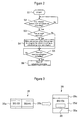
- FIG. 2 is a flowchart illustrating an example of screen display processing according to the present embodiment
- Figure 3 is a diagram illustrating a specific display state.
- step S2 the control unit determines whether or not the display unit 35 currently displays two or more screens, and if the display unit 35 is displaying two or more screens (Yes: in the display unit 35 shown in Figure 3 , a TV program on the BS103 channel is displayed in a display area 35a and a TV program on BS141 is displayed on a display area 35b), the processing proceeds to step S4, and before the time for starting the scheduled recording, the control unit controls the display so that: a screen other than the screen for the program scheduled to be recorded, that is, one of the screens, which displays a channel not selected for a scheduled recording, is made to remain; and if a program on the channel for which the recording is scheduled is displayed, the screen is not displayed on the display unit (e.g., makes the screen go into non-display).
- step S5 if it is determined at step S5 that the time has reached the time for starting the scheduled recording (Yes), the processing proceeds to step S6, and the scheduled recording is started.
- step S6 it is favorable that, for example, a message to inform a user of the start of the scheduled recording is displayed on the display area indicated by reference numeral 36.
- processing such as switching the channel to another, cannot be performed even if he/she switches the screen back to multi-screen display.
- the display is controlled so that the program for which a recording is scheduled among them is not displayed, providing the advantage of preventing an unwanted message, such as "no channel selection is allowed," from being displayed in response to the user's operation that may be performed when the program for which a recording is scheduled is still displayed on the screen.
- the display of the remaining program may be expanded according to the area that can provide display, which is widened because of non-display of the program for which a recording is scheduled or may also be made to be a margin area.
- the program for which a recording is scheduled may be displayed in a sub-screen or only the channel number of the program may be displayed.
- Figure 4 is a diagram illustrating another display example of that shown in Figure 3 .
- a program on BS103 is displayed in a display area 135a
- a program on BS141 is displayed in a display area 135b
- a Web screen 135c obtained via the Internet is displayed on the display area 135c.
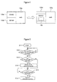
- Figure 5 is a flowchart illustrating the flow of display control processing according to the second modification.
- Figure 6 is a diagram illustrating an example of display following the flow shown in Figure 5 . It is a diagram illustrating an example of the case where two screens including a Web screen is displayed.
- the control unit 27 starts processing for display control (step S11).
- the control unit 27 determines whether or not the display unit 135 currently display two or more screens including Web display via the Internet (step S13), and as shown in the left-side drawing in Figure 6 , if it displays two or more screens that provide first display 135b on the BS103 channel and Web display 135d (Yes), the processing proceeds to step S14, and before the time for starting the scheduled recording, the control unit controls the display so that a screen other than the screen for the program scheduled to be recorded, that is, the screen which displays a channel not selected for a scheduled recording (BS103) is made to go into non-display, and as shown in 135e in Figure 6 , only one screen that provides the Web
- the digital TV receiver during multi-screen display, if a recording is scheduled for a program on the same channel as that of the displayed program, when the time has reached the time a certain period of time before the start of recording based on the scheduled recording, the display of the program on the channel for which the recording is scheduled is made to disappear, resulting in that only the remaining program or Web screens are displayed.
- Which program to turn into non-display according to the scheduled recording may be determined via the settings by the user.
- control is performed to make the display of programs for which the recordings are scheduled disappear at times a short period of time before the times of the respective recordings.
- control may be performed so as to disable operations related to a program for which a recording is scheduled.
- the present invention can be employed for a digital broadcast receiver that can provide multi-screen display.
Landscapes
- Engineering & Computer Science (AREA)
- Multimedia (AREA)
- Signal Processing (AREA)
- Human Computer Interaction (AREA)
- Business, Economics & Management (AREA)
- Finance (AREA)
- Strategic Management (AREA)
- Databases & Information Systems (AREA)
- Software Systems (AREA)
- Marketing (AREA)
- Two-Way Televisions, Distribution Of Moving Picture Or The Like (AREA)
- Television Signal Processing For Recording (AREA)
- User Interface Of Digital Computer (AREA)
Abstract
Description
- The present invention relates to a digital broadcast receiver, and specifically relates to a display control technique related to multi-screen display.
- Since when analog broadcast receivers had predominated, techniques for displaying plural programs on one display unit have been used. Furthermore, at the present time when digital broadcast receivers are becoming mainstream, devices capable of multi-screen display are growing popular. For example, for the digital broadcast receiver disclosed in
patent document 1,patent document 1 discloses a technique for display two screens of a TV display screen and an Internet screen and also discloses a technique for smoothly switching these screens. - Patent Document 1:
JP Patent Publication (Kokai) No. 2005-244716 A - In conventional art including the techniques disclosed in
patent document 1, for example, when processing for scheduled recording of a program is started during two screen display being provided for TV programs, one of the two screens displaying TV programs is changed to display the channel on which the scheduled recording is performed. When such change of display occurs, the user will be surprised because the program he/she was viewing until then is suddenly switched to another. Also in the subsequent processing, each time the user operates a remoter controller to, e.g., switch the channel on the screen whose display has been switched to the channel on which the scheduled recording, to another, a message to inform the use of no channel selection being allowed is displayed, which may be annoying. - An object of the present invention is to provide a display control technique that does not give a sense of discomfort to users even when processing for a scheduled recording is started during multi-screen display being provided.
- An aspect of the present invention provides a broadcast receiver capable of providing multi-screen display on a display unit, characterized by comprising a display control unit that performs display control to make at least one screen in a multi-screen go into non-display at a point of time when the time for starting a scheduled recording approaches during multi-screen display. Consequently, a futile operation, which cannot actually be performed, will not be repeatedly performed for a program for which a scheduled recording is performed.
- The aspect of the present invention is characterized in that the display control unit performs control to expand a remaining program using the non-display area. Consequently, the area of the display unit that has gone into non-display can effectively be used. The aspect of the present invention is characterized in that the display control unit displays a message relating to the start of the scheduled recording when the time for starting the scheduled recording approaches. For example, it is possible to let a user know that the aforementioned control is being performed correctly, via a message to inform the user of the start of a scheduled recording.
- The aspect of the present invention is characterized in that display provided by the display unit includes display of information obtained via the Internet, and if there is no remaining program, only the display based on the Internet is made to remain. Display based on the Internet can be provided all the time, and thus is suitable for screen display that remains last.
- The display control unit can perform control to display an identification number for the non-displayed channel on the display unit. Consequently, the ID of a program that is currently being recorded according to a scheduled recording can be recognized.
- Another aspect of the present invention provides a display control method for a broadcast receiver capable of providing multi-screen display on a display unit, characterized by comprising the steps of: making at least one screen in a multi-screen go into non-display at a point of time when the time for starting a scheduled recording of a currently-displayed program approaches during multi-screen display; and expanding the display of a currently-displayed program to the non-display area. A program for making a computer execute these steps also falls within the scope of the present invention.
- According to the present invention, the screen display state is automatically switched to another so that a user cannot view the channel on which recording is performed, avoiding the user from being annoyed by a message to inform the user of no channel selection being allowed being displayed in response to the user's operation. Also, the display screen can be expanded to the area of the non-display screen, enabling effective use of the display screen.
-
-
Figure 1 is a function block diagram illustrating an example configuration of a digital broadcast receiver according to an embodiment of the present invention. -
Figure 2 is a flowchart illustrating an example of screen display processing according to an embodiment of the present invention. -
Figure 3 is a diagram illustrating a specific display state. -
Figure 4 is a diagram illustrating an example of screen display according to a first modification of an embodiment of the present invention, which is another display example of that shown inFigure 3 . -
Figure 5 is a flowchart illustrating the flow of display control processing according to a second modification of an embodiment of the present invention. -
Figure 6 is a diagram illustrating an example of display following the flow shown inFigure 5 . - A...digital broadcast receiver, 1...antenna, 3...front-end circuit (A), 5...demultiplexer (A), 7...picture and sound decoding unit (A), 11...front-end circuit (B), 15...demultiplexer (B), 17...picture and sound decoding unit (B), 21...screen combining unit, 23...RAM, 24...timer, 25...ROM, 27...control unit (CPU), 33...sound switching unit, 35...display unit, 37...sound output unit (A), 41...sound output unit (B), 45...remote controller light receiving unit.
- Hereinafter, a digital broadcast receiver according to an embodiment of the present invention will be described with reference to the drawings.
Figure 1 is a function block diagram illustrating an example configuration of a digital broadcast receiver according to the present embodiment. As shown inFigure 1 , a digital broadcast receiver A according to the present embodiment includes anantenna 1, a front-end circuit (A) 3, a demultiplexer (A) 5, a picture and sound decoding unit (A) 7, a front-end circuit (B) 11, a demultiplexer (B) 15, a picture and sound decoding unit (B) 17, and atimer 24 so that it can provide multi-screen display. In each of the front-end circuits, a tuner circuit, an IF demodulating circuit and a DC/DC converter circuit are integrated. Inputs from these two lines are combined by means of ascreen combining unit 21 and displayed on adisplay unit 35, and in asound switching unit 33, they are output to a sound output unit (A)37 and a sound output unit (B)41. - In a common configuration, the digital broadcast receiver further includes a
ROM 25 that stores programs, etc., and aRAM 23 that develops the programs and processing them at high speed, a control unit (CPU) 27 that performs overall control, and a remote controllerlight receiving unit 45 that receives signals from a remoter controller. In addition, the digital broadcast receiver is provided with an Ethernet unit 43, and thecontrol unit 27 is provided with an HTML browser, etc.., enabling, e.g., obtaining contents via the Internet (NT) and displaying them on thedisplay unit 35. -
Figure 2 is a flowchart illustrating an example of screen display processing according to the present embodiment, andFigure 3 is a diagram illustrating a specific display state. Where the remote controllerlight receiving unit 45 has received an instruction for a scheduled recording from a remote controller (not shown) during programs, etc., displayed on the digital TV receiver being viewed, thecontrol unit 27 starts processing for display control (step S1). When the time has reached a predetermined period of time counted by thetimer 24, for example, two minutes, before the start of the scheduled recording (step S2), the control unit determines whether or not thedisplay unit 35 currently displays two or more screens, and if thedisplay unit 35 is displaying two or more screens (Yes: in thedisplay unit 35 shown inFigure 3 , a TV program on the BS103 channel is displayed in adisplay area 35a and a TV program on BS141 is displayed on adisplay area 35b), the processing proceeds to step S4, and before the time for starting the scheduled recording, the control unit controls the display so that: a screen other than the screen for the program scheduled to be recorded, that is, one of the screens, which displays a channel not selected for a scheduled recording, is made to remain; and if a program on the channel for which the recording is scheduled is displayed, the screen is not displayed on the display unit (e.g., makes the screen go into non-display). For example, as shown in the right-side drawing inFigure 3 , on theTV screen 35, display of a program on the BS 141 channel on which recording has been scheduled has disappeared, and only theremaining display 35d for BS103 is displayed. Whether or notmargin areas - Next, if it is determined at step S5 that the time has reached the time for starting the scheduled recording (Yes), the processing proceeds to step S6, and the scheduled recording is started. At this time, it is favorable that, for example, a message to inform a user of the start of the scheduled recording is displayed on the display area indicated by
reference numeral 36. As a result of informing the user of the scheduled recording being underway via this display, it is possible to let the user know that processing, such as switching the channel to another, cannot be performed even if he/she switches the screen back to multi-screen display. - As described above, when plural programs including a program for which a recording is scheduled are displayed, the display is controlled so that the program for which a recording is scheduled among them is not displayed, providing the advantage of preventing an unwanted message, such as "no channel selection is allowed," from being displayed in response to the user's operation that may be performed when the program for which a recording is scheduled is still displayed on the screen. The display of the remaining program may be expanded according to the area that can provide display, which is widened because of non-display of the program for which a recording is scheduled or may also be made to be a margin area. In other words, the program for which a recording is scheduled may be displayed in a sub-screen or only the channel number of the program may be displayed.
- Next, a first modification of the present embodiment will be described with reference to the drawings.
Figure 4 is a diagram illustrating another display example of that shown inFigure 3 . In the drawing shown in the left side ofFigure 4 , a program on BS103 is displayed in adisplay area 135a, a program on BS141 is displayed in adisplay area 135b, and aWeb screen 135c obtained via the Internet is displayed on thedisplay area 135c. In this multi-screen display state, as with the case ofFigure 3 , if recording of a program on BS141 is scheduled, as shown in the right-side drawing inFigure 4 , the program on BS141 goes into non-display, e.g., approximately two minutes before the start of the scheduled recording, the display of the program on BS103 and the display of theWeb screen 135c remain. Furthermore, a message to inform a user of the start of the scheduled recording may be displayed in anarea 136. When the scheduled recording has been finished, a program on the same channel may be displayed, or may also not be displayed. Which to choose may be set in advance. As described above, the principle is the same between the case where a Web screen obtained via the Internet is displayed and the case where broadcast programs are displayed on a multi-screen (the first modification). - Next, a second modification of the present embodiment will be described with reference to the drawings.
Figure 5 is a flowchart illustrating the flow of display control processing according to the second modification.Figure 6 is a diagram illustrating an example of display following the flow shown inFigure 5 . It is a diagram illustrating an example of the case where two screens including a Web screen is displayed. - As shown in
Figure 5 (andFigure 1 ), where the remote controllerlight receiving unit 45 has received an instruction for a scheduled recording from the remoter controller (not shown), thecontrol unit 27 starts processing for display control (step S11). When the time has reached a predetermined period of time counted by the timer, for example, two minutes, before the start of the scheduled recording (step S12), thecontrol unit 27 determines whether or not thedisplay unit 135 currently display two or more screens including Web display via the Internet (step S13), and as shown in the left-side drawing inFigure 6 , if it displays two or more screens that providefirst display 135b on the BS103 channel andWeb display 135d (Yes), the processing proceeds to step S14, and before the time for starting the scheduled recording, the control unit controls the display so that a screen other than the screen for the program scheduled to be recorded, that is, the screen which displays a channel not selected for a scheduled recording (BS103) is made to go into non-display, and as shown in 135e inFigure 6 , only one screen that provides the Web display is displayed on the display unit, and the control unit makes amessage 137 to inform a user of the start of the scheduled recording be displayed. Next, if it is determined at step S 15 that the time has reached the time for the start of the scheduled recording (Yes), the scheduled recording of, e.g., a program on BS103 is started at step S16. - As described above, according the digital TV receiver according to the present embodiment, during multi-screen display, if a recording is scheduled for a program on the same channel as that of the displayed program, when the time has reached the time a certain period of time before the start of recording based on the scheduled recording, the display of the program on the channel for which the recording is scheduled is made to disappear, resulting in that only the remaining program or Web screens are displayed. Which program to turn into non-display according to the scheduled recording may be determined via the settings by the user.
- Accordingly, it is possible to prevent the user from mistakenly recognize the program as a program being currently viewed, for which a scheduled recording is not underway, and performing processing for switching the program to another. Thus, the advantage of reducing futileness and annoyance related to users' operations can be obtained.
- Although the above embodiment has been described in terms of a digital broadcast receiver as an example, it should be understood that analog broadcasting may be mixed.
- Also, when plural recordings are scheduled, it is preferable the control is performed to make the display of programs for which the recordings are scheduled disappear at times a short period of time before the times of the respective recordings. Where an interactive communication-enabled remoter controller is used, the control may be performed so as to disable operations related to a program for which a recording is scheduled.
- The present invention can be employed for a digital broadcast receiver that can provide multi-screen display.
Claims (7)
- A broadcast receiver capable of providing multi-screen display on a display unit, characterized by comprising a display control unit that performs display control to make at least one screen in a multi-screen go into non-display at a point of time when the time for starting a scheduled recording for a currently-displayed program approaches during multi-screen display.
- The broadcast receiver according to claim 1, characterized in that the display control unit performs control to expand a remaining program using the non-display area.
- The broadcast receiver according to claim 1 or 2, characterized in that the display control unit displays a message relating to the start of the scheduled recording when the time for starting the scheduled recording approaches.
- The broadcast receiver according to any one of claims 1 to 3, characterized in that display provided by the display unit includes display of information obtained via the Internet, and if there is no remaining program, only the display based on the Internet is made to remain.
- The broadcast receiver according to any one of claims 1 to 4, characterized in that the display control unit performs control to display an identification number for the non-displayed channel on the display unit.
- A display control method for a broadcast receiver capable of providing multi-screen display on a display unit, characterized by comprising the steps of:making at least one screen in a multi-screen go into non-display at a point of time when the time for starting a scheduled recording of a currently-displayed program approaches during multi-screen display; andexpanding the display of a currently-displayed program to the non-display area.
- A program for making a computer execute the steps according to claim 6.
Applications Claiming Priority (2)
| Application Number | Priority Date | Filing Date | Title |
|---|---|---|---|
| JP2006205990A JP4181589B2 (en) | 2006-07-28 | 2006-07-28 | Digital broadcast receiver |
| PCT/JP2007/059874 WO2008012980A1 (en) | 2006-07-28 | 2007-05-14 | Digital broadcast receiver |
Publications (3)
| Publication Number | Publication Date |
|---|---|
| EP2086233A1 true EP2086233A1 (en) | 2009-08-05 |
| EP2086233A4 EP2086233A4 (en) | 2010-10-27 |
| EP2086233B1 EP2086233B1 (en) | 2012-04-11 |
Family
ID=38981295
Family Applications (1)
| Application Number | Title | Priority Date | Filing Date |
|---|---|---|---|
| EP07743309A Ceased EP2086233B1 (en) | 2006-07-28 | 2007-05-14 | Digital broadcast receiver |
Country Status (6)
| Country | Link |
|---|---|
| US (1) | US8296809B2 (en) |
| EP (1) | EP2086233B1 (en) |
| JP (1) | JP4181589B2 (en) |
| KR (1) | KR101027895B1 (en) |
| CN (1) | CN101513061B (en) |
| WO (1) | WO2008012980A1 (en) |
Families Citing this family (6)
| Publication number | Priority date | Publication date | Assignee | Title |
|---|---|---|---|---|
| JP5106151B2 (en) | 2008-01-28 | 2012-12-26 | 株式会社東芝 | Stacked stack NAND memory and semiconductor device |
| JP5106312B2 (en) * | 2008-08-11 | 2012-12-26 | 株式会社東芝 | Remote control device, device, and wireless control system |
| US11274998B2 (en) | 2012-12-26 | 2022-03-15 | Ventana Medical Systems, Inc. | Specimen processing systems and methods for holding slides |
| CA2893501A1 (en) | 2012-12-26 | 2014-07-03 | Ventana Medical Systems, Inc. | Specimen processing systems and methods for aligning slides |
| US9989448B2 (en) | 2012-12-26 | 2018-06-05 | Ventana Medical Systems, Inc. | Specimen processing systems and methods for holding slides |
| KR102138525B1 (en) * | 2014-01-13 | 2020-07-28 | 엘지전자 주식회사 | Display device and method for controlling the same |
Family Cites Families (10)
| Publication number | Priority date | Publication date | Assignee | Title |
|---|---|---|---|---|
| JP3360705B2 (en) * | 1994-12-21 | 2002-12-24 | ソニー株式会社 | Broadcast receiving device and broadcast receiving method |
| US6052145A (en) * | 1995-01-05 | 2000-04-18 | Gemstar Development Corporation | System and method for controlling the broadcast and recording of television programs and for distributing information to be displayed on a television screen |
| JPH08237563A (en) * | 1995-02-28 | 1996-09-13 | Toshiba Corp | Television receiver |
| CA2666635C (en) * | 2001-02-21 | 2016-03-22 | United Video Properties, Inc. | Systems and methods for interactive program guides with personal video recording features |
| JP4261893B2 (en) * | 2002-12-13 | 2009-04-30 | キヤノン株式会社 | Information processing apparatus and information processing method |
| JP2005026821A (en) * | 2003-06-30 | 2005-01-27 | Sharp Corp | Television receiver with channel fixing function |
| JP2005124047A (en) * | 2003-10-20 | 2005-05-12 | Canon Inc | Display device |
| JP2005244716A (en) | 2004-02-27 | 2005-09-08 | Toshiba Corp | Television broadcast receiver |
| JP2006041933A (en) * | 2004-07-27 | 2006-02-09 | Sharp Corp | Recording / reproducing apparatus and television broadcast receiving apparatus |
| JP2006221585A (en) * | 2005-01-12 | 2006-08-24 | Fuji Photo Film Co Ltd | Screen saver controller, screen saver control method and screen saver control program |
-
2006
- 2006-07-28 JP JP2006205990A patent/JP4181589B2/en not_active Expired - Fee Related
-
2007
- 2007-05-14 WO PCT/JP2007/059874 patent/WO2008012980A1/en not_active Ceased
- 2007-05-14 US US12/374,091 patent/US8296809B2/en not_active Expired - Fee Related
- 2007-05-14 CN CN200780033372.2A patent/CN101513061B/en not_active Expired - Fee Related
- 2007-05-14 EP EP07743309A patent/EP2086233B1/en not_active Ceased
- 2007-05-14 KR KR1020097004286A patent/KR101027895B1/en not_active Expired - Fee Related
Also Published As
| Publication number | Publication date |
|---|---|
| WO2008012980A1 (en) | 2008-01-31 |
| JP4181589B2 (en) | 2008-11-19 |
| KR20090035032A (en) | 2009-04-08 |
| CN101513061B (en) | 2014-02-26 |
| EP2086233A4 (en) | 2010-10-27 |
| US8296809B2 (en) | 2012-10-23 |
| JP2008035179A (en) | 2008-02-14 |
| KR101027895B1 (en) | 2011-04-07 |
| CN101513061A (en) | 2009-08-19 |
| US20090256966A1 (en) | 2009-10-15 |
| EP2086233B1 (en) | 2012-04-11 |
Similar Documents
| Publication | Publication Date | Title |
|---|---|---|
| EP2086233B1 (en) | Digital broadcast receiver | |
| JP2009088977A (en) | Program information display system, program information display method, and television system | |
| JP4562606B2 (en) | Receiving apparatus and receiving method | |
| US8407739B2 (en) | Apparatus and method for displaying broadcasting program guide information | |
| US8863179B2 (en) | Digital broadcast receiver | |
| EP2164252A1 (en) | Video display device | |
| JP2009182827A (en) | Information processing apparatus and information providing method | |
| EP1406442A2 (en) | Teletext-enabled television apparatus | |
| JP4718296B2 (en) | Digital broadcast receiver having program information display function for displaying program information | |
| JP2007288717A (en) | Video processing device, and television receiving device | |
| KR100560876B1 (en) | Alarm Setting Device and Method of Digital TV | |
| JPH1155593A (en) | Receiver | |
| JP4249953B2 (en) | Television receiver | |
| JP4645619B2 (en) | Display device | |
| JP4528172B2 (en) | Television receiver and power supply control method thereof | |
| JP2005142827A (en) | Video receiver | |
| JP2003032560A (en) | Tuning device | |
| JP2004120388A (en) | Digital broadcast receiver and broadcast signal receiver | |
| JP2007251369A (en) | Television receiver and display control method for television receiver | |
| KR20060072178A (en) | Apparatus and method for controlling data execution in data broadcasting | |
| KR20050122805A (en) | Channel number display position moving apparatus and method for television | |
| JP2011205311A (en) | Information receiving apparatus | |
| JP2007067589A (en) | Display device and data broadcast display method | |
| JPH10257445A (en) | Data broadcast receiving method and data broadcast receiving device | |
| KR20040037615A (en) | Digital TV and controlling of the same method |
Legal Events
| Date | Code | Title | Description |
|---|---|---|---|
| PUAI | Public reference made under article 153(3) epc to a published international application that has entered the european phase |
Free format text: ORIGINAL CODE: 0009012 |
|
| 17P | Request for examination filed |
Effective date: 20090210 |
|
| AK | Designated contracting states |
Kind code of ref document: A1 Designated state(s): AT BE BG CH CY CZ DE DK EE ES FI FR GB GR HU IE IS IT LI LT LU LV MC MT NL PL PT RO SE SI SK TR |
|
| AX | Request for extension of the european patent |
Extension state: AL BA HR MK RS |
|
| RIN1 | Information on inventor provided before grant (corrected) |
Inventor name: HIROTA, TORU |
|
| DAX | Request for extension of the european patent (deleted) | ||
| A4 | Supplementary search report drawn up and despatched |
Effective date: 20100928 |
|
| RIC1 | Information provided on ipc code assigned before grant |
Ipc: H04N 7/173 20060101AFI20080319BHEP Ipc: H04N 5/445 20060101ALI20100922BHEP |
|
| REG | Reference to a national code |
Ref country code: DE Ref legal event code: R079 Ref document number: 602007021919 Country of ref document: DE Free format text: PREVIOUS MAIN CLASS: H04N0007173000 Ipc: H04N0005450000 |
|
| GRAP | Despatch of communication of intention to grant a patent |
Free format text: ORIGINAL CODE: EPIDOSNIGR1 |
|
| GRAC | Information related to communication of intention to grant a patent modified |
Free format text: ORIGINAL CODE: EPIDOSCIGR1 |
|
| RIC1 | Information provided on ipc code assigned before grant |
Ipc: H04N 7/173 20110101ALI20110905BHEP Ipc: H04N 5/45 20110101AFI20110905BHEP Ipc: H04N 5/445 20110101ALI20110905BHEP |
|
| RBV | Designated contracting states (corrected) |
Designated state(s): DE ES FR GB |
|
| RIN1 | Information on inventor provided before grant (corrected) |
Inventor name: HIROTA, TORU |
|
| GRAS | Grant fee paid |
Free format text: ORIGINAL CODE: EPIDOSNIGR3 |
|
| GRAA | (expected) grant |
Free format text: ORIGINAL CODE: 0009210 |
|
| AK | Designated contracting states |
Kind code of ref document: B1 Designated state(s): DE ES FR GB |
|
| REG | Reference to a national code |
Ref country code: GB Ref legal event code: FG4D |
|
| REG | Reference to a national code |
Ref country code: DE Ref legal event code: R096 Ref document number: 602007021919 Country of ref document: DE Effective date: 20120606 |
|
| PLBE | No opposition filed within time limit |
Free format text: ORIGINAL CODE: 0009261 |
|
| STAA | Information on the status of an ep patent application or granted ep patent |
Free format text: STATUS: NO OPPOSITION FILED WITHIN TIME LIMIT |
|
| 26N | No opposition filed |
Effective date: 20130114 |
|
| PG25 | Lapsed in a contracting state [announced via postgrant information from national office to epo] |
Ref country code: ES Free format text: LAPSE BECAUSE OF FAILURE TO SUBMIT A TRANSLATION OF THE DESCRIPTION OR TO PAY THE FEE WITHIN THE PRESCRIBED TIME-LIMIT Effective date: 20120722 |
|
| REG | Reference to a national code |
Ref country code: DE Ref legal event code: R097 Ref document number: 602007021919 Country of ref document: DE Effective date: 20130114 |
|
| REG | Reference to a national code |
Ref country code: FR Ref legal event code: PLFP Year of fee payment: 10 |
|
| REG | Reference to a national code |
Ref country code: FR Ref legal event code: PLFP Year of fee payment: 11 |
|
| REG | Reference to a national code |
Ref country code: FR Ref legal event code: PLFP Year of fee payment: 12 |
|
| PGFP | Annual fee paid to national office [announced via postgrant information from national office to epo] |
Ref country code: DE Payment date: 20180522 Year of fee payment: 12 |
|
| PGFP | Annual fee paid to national office [announced via postgrant information from national office to epo] |
Ref country code: FR Payment date: 20180522 Year of fee payment: 12 |
|
| PGFP | Annual fee paid to national office [announced via postgrant information from national office to epo] |
Ref country code: GB Payment date: 20180518 Year of fee payment: 12 |
|
| REG | Reference to a national code |
Ref country code: DE Ref legal event code: R119 Ref document number: 602007021919 Country of ref document: DE |
|
| GBPC | Gb: european patent ceased through non-payment of renewal fee |
Effective date: 20190514 |
|
| PG25 | Lapsed in a contracting state [announced via postgrant information from national office to epo] |
Ref country code: GB Free format text: LAPSE BECAUSE OF NON-PAYMENT OF DUE FEES Effective date: 20190514 Ref country code: DE Free format text: LAPSE BECAUSE OF NON-PAYMENT OF DUE FEES Effective date: 20191203 |
|
| PG25 | Lapsed in a contracting state [announced via postgrant information from national office to epo] |
Ref country code: FR Free format text: LAPSE BECAUSE OF NON-PAYMENT OF DUE FEES Effective date: 20190531 |