EP2086151B1 - Method and apparatus for supporting HARQ by using at least one transmission parameter of a channel quality indicator CQI - Google Patents
Method and apparatus for supporting HARQ by using at least one transmission parameter of a channel quality indicator CQI Download PDFInfo
- Publication number
- EP2086151B1 EP2086151B1 EP09001445.7A EP09001445A EP2086151B1 EP 2086151 B1 EP2086151 B1 EP 2086151B1 EP 09001445 A EP09001445 A EP 09001445A EP 2086151 B1 EP2086151 B1 EP 2086151B1
- Authority
- EP
- European Patent Office
- Prior art keywords
- cqi
- uplink
- data
- retransmission
- transmission
- Prior art date
- Legal status (The legal status is an assumption and is not a legal conclusion. Google has not performed a legal analysis and makes no representation as to the accuracy of the status listed.)
- Active
Links
- 230000005540 biological transmission Effects 0.000 title claims description 100
- 238000000034 method Methods 0.000 title claims description 34
- 238000004891 communication Methods 0.000 claims description 26
- 238000013468 resource allocation Methods 0.000 claims description 17
- 230000000737 periodic effect Effects 0.000 claims description 7
- 238000010586 diagram Methods 0.000 description 12
- 230000011664 signaling Effects 0.000 description 9
- 238000005516 engineering process Methods 0.000 description 5
- 230000004044 response Effects 0.000 description 5
- 230000003044 adaptive effect Effects 0.000 description 3
- 230000007774 longterm Effects 0.000 description 3
- 125000004122 cyclic group Chemical group 0.000 description 2
- 230000006870 function Effects 0.000 description 2
- 238000013507 mapping Methods 0.000 description 2
- 239000011159 matrix material Substances 0.000 description 2
- 238000007476 Maximum Likelihood Methods 0.000 description 1
- 230000004913 activation Effects 0.000 description 1
- 238000013459 approach Methods 0.000 description 1
- 238000012937 correction Methods 0.000 description 1
- 238000011161 development Methods 0.000 description 1
- 230000018109 developmental process Effects 0.000 description 1
- VJYFKVYYMZPMAB-UHFFFAOYSA-N ethoprophos Chemical compound CCCSP(=O)(OCC)SCCC VJYFKVYYMZPMAB-UHFFFAOYSA-N 0.000 description 1
- 238000005562 fading Methods 0.000 description 1
- GVVPGTZRZFNKDS-JXMROGBWSA-N geranyl diphosphate Chemical compound CC(C)=CCC\C(C)=C\CO[P@](O)(=O)OP(O)(O)=O GVVPGTZRZFNKDS-JXMROGBWSA-N 0.000 description 1
- 239000004973 liquid crystal related substance Substances 0.000 description 1
- 238000010295 mobile communication Methods 0.000 description 1
- 230000002085 persistent effect Effects 0.000 description 1
- 230000010363 phase shift Effects 0.000 description 1
- 230000011218 segmentation Effects 0.000 description 1
- 230000003595 spectral effect Effects 0.000 description 1
- 208000037918 transfusion-transmitted disease Diseases 0.000 description 1
Images


Classifications
-
- H—ELECTRICITY
- H04—ELECTRIC COMMUNICATION TECHNIQUE
- H04L—TRANSMISSION OF DIGITAL INFORMATION, e.g. TELEGRAPHIC COMMUNICATION
- H04L1/00—Arrangements for detecting or preventing errors in the information received
- H04L1/12—Arrangements for detecting or preventing errors in the information received by using return channel
- H04L1/16—Arrangements for detecting or preventing errors in the information received by using return channel in which the return channel carries supervisory signals, e.g. repetition request signals
- H04L1/18—Automatic repetition systems, e.g. Van Duuren systems
- H04L1/1829—Arrangements specially adapted for the receiver end
- H04L1/1861—Physical mapping arrangements
-
- H—ELECTRICITY
- H04—ELECTRIC COMMUNICATION TECHNIQUE
- H04L—TRANSMISSION OF DIGITAL INFORMATION, e.g. TELEGRAPHIC COMMUNICATION
- H04L1/00—Arrangements for detecting or preventing errors in the information received
- H04L1/0001—Systems modifying transmission characteristics according to link quality, e.g. power backoff
- H04L1/0002—Systems modifying transmission characteristics according to link quality, e.g. power backoff by adapting the transmission rate
- H04L1/0003—Systems modifying transmission characteristics according to link quality, e.g. power backoff by adapting the transmission rate by switching between different modulation schemes
- H04L1/0004—Systems modifying transmission characteristics according to link quality, e.g. power backoff by adapting the transmission rate by switching between different modulation schemes applied to control information
-
- H—ELECTRICITY
- H04—ELECTRIC COMMUNICATION TECHNIQUE
- H04L—TRANSMISSION OF DIGITAL INFORMATION, e.g. TELEGRAPHIC COMMUNICATION
- H04L1/00—Arrangements for detecting or preventing errors in the information received
- H04L1/0001—Systems modifying transmission characteristics according to link quality, e.g. power backoff
- H04L1/0023—Systems modifying transmission characteristics according to link quality, e.g. power backoff characterised by the signalling
- H04L1/0026—Transmission of channel quality indication
-
- H—ELECTRICITY
- H04—ELECTRIC COMMUNICATION TECHNIQUE
- H04L—TRANSMISSION OF DIGITAL INFORMATION, e.g. TELEGRAPHIC COMMUNICATION
- H04L1/00—Arrangements for detecting or preventing errors in the information received
- H04L1/0001—Systems modifying transmission characteristics according to link quality, e.g. power backoff
- H04L1/0023—Systems modifying transmission characteristics according to link quality, e.g. power backoff characterised by the signalling
- H04L1/0027—Scheduling of signalling, e.g. occurrence thereof
-
- H—ELECTRICITY
- H04—ELECTRIC COMMUNICATION TECHNIQUE
- H04L—TRANSMISSION OF DIGITAL INFORMATION, e.g. TELEGRAPHIC COMMUNICATION
- H04L1/00—Arrangements for detecting or preventing errors in the information received
- H04L1/12—Arrangements for detecting or preventing errors in the information received by using return channel
- H04L1/16—Arrangements for detecting or preventing errors in the information received by using return channel in which the return channel carries supervisory signals, e.g. repetition request signals
- H04L1/18—Automatic repetition systems, e.g. Van Duuren systems
- H04L1/1829—Arrangements specially adapted for the receiver end
- H04L1/1854—Scheduling and prioritising arrangements
-
- H—ELECTRICITY
- H04—ELECTRIC COMMUNICATION TECHNIQUE
- H04L—TRANSMISSION OF DIGITAL INFORMATION, e.g. TELEGRAPHIC COMMUNICATION
- H04L1/00—Arrangements for detecting or preventing errors in the information received
- H04L1/12—Arrangements for detecting or preventing errors in the information received by using return channel
- H04L1/16—Arrangements for detecting or preventing errors in the information received by using return channel in which the return channel carries supervisory signals, e.g. repetition request signals
- H04L1/18—Automatic repetition systems, e.g. Van Duuren systems
- H04L1/1867—Arrangements specially adapted for the transmitter end
- H04L1/1887—Scheduling and prioritising arrangements
-
- H—ELECTRICITY
- H04—ELECTRIC COMMUNICATION TECHNIQUE
- H04L—TRANSMISSION OF DIGITAL INFORMATION, e.g. TELEGRAPHIC COMMUNICATION
- H04L5/00—Arrangements affording multiple use of the transmission path
- H04L5/003—Arrangements for allocating sub-channels of the transmission path
- H04L5/0053—Allocation of signaling, i.e. of overhead other than pilot signals
- H04L5/0057—Physical resource allocation for CQI
-
- H—ELECTRICITY
- H04—ELECTRIC COMMUNICATION TECHNIQUE
- H04W—WIRELESS COMMUNICATION NETWORKS
- H04W72/00—Local resource management
- H04W72/20—Control channels or signalling for resource management
- H04W72/21—Control channels or signalling for resource management in the uplink direction of a wireless link, i.e. towards the network
-
- H—ELECTRICITY
- H04—ELECTRIC COMMUNICATION TECHNIQUE
- H04W—WIRELESS COMMUNICATION NETWORKS
- H04W72/00—Local resource management
- H04W72/20—Control channels or signalling for resource management
- H04W72/23—Control channels or signalling for resource management in the downlink direction of a wireless link, i.e. towards a terminal
-
- H—ELECTRICITY
- H04—ELECTRIC COMMUNICATION TECHNIQUE
- H04L—TRANSMISSION OF DIGITAL INFORMATION, e.g. TELEGRAPHIC COMMUNICATION
- H04L1/00—Arrangements for detecting or preventing errors in the information received
- H04L1/0001—Systems modifying transmission characteristics according to link quality, e.g. power backoff
- H04L1/0009—Systems modifying transmission characteristics according to link quality, e.g. power backoff by adapting the channel coding
-
- H—ELECTRICITY
- H04—ELECTRIC COMMUNICATION TECHNIQUE
- H04L—TRANSMISSION OF DIGITAL INFORMATION, e.g. TELEGRAPHIC COMMUNICATION
- H04L1/00—Arrangements for detecting or preventing errors in the information received
- H04L1/12—Arrangements for detecting or preventing errors in the information received by using return channel
- H04L1/16—Arrangements for detecting or preventing errors in the information received by using return channel in which the return channel carries supervisory signals, e.g. repetition request signals
- H04L1/18—Automatic repetition systems, e.g. Van Duuren systems
- H04L1/1812—Hybrid protocols; Hybrid automatic repeat request [HARQ]
Definitions
- the present invention relates to wireless communications, and more particularly, to a method and apparatus for supporting hybrid automatic repeat request (HARQ) in a wireless communication system.
- HARQ hybrid automatic repeat request
- Wireless communication systems are widely spread all over the world to provide various types of communication services such as voice or data.
- the wireless communication system is a multiple access system capable of supporting communication with multiple users by sharing available system resources (e.g., bandwidth, transmission power, etc.).
- Examples of the multiple access system include a code division multiple access (CDMA) system, a frequency division multiple access (FDMA) system, a time division multiple access (TDMA) system, an orthogonal frequency division multiple access (OFDMA) system, a single carrier frequency division multiple access (SC-FDMA) system, etc.
- CDMA code division multiple access
- FDMA frequency division multiple access
- TDMA time division multiple access
- OFDMA orthogonal frequency division multiple access
- SC-FDMA single carrier frequency division multiple access
- Hybrid automatic repeat request is an ARQ protocol combined with forward error correction (FEC) and is strongly considered as one of cutting edge technologies for future reliable communication.
- the HARQ scheme can largely be classified into two types. One is HARQ-chase combining (CC) which is disclosed in D. Chase, Code Combining: A maximum-likelihood decoding approach for combining an arbitrary number of noisy packets, IEEE Trans. on Commun., Vol. 33, pp. 593-607, May 1985 . The other is HARQ-Increment Redundancy (IR).
- CC HARQ-chase combining
- IR HARQ-Increment Redundancy
- the HARQ-CC when a receiver detects an error through cyclic redundancy checking (CRC) while decoding the transmitted packet, the same packet with the same modulation and coding is retransmitted to the receiver. Meanwhile, in order to achieve a coding gain, the HARQ-IR retransmits different packets, in which parity bits can be manipulated through puncturing and repetition. To perform the HARQ, there is a need to exchange acknowledgement (ACK)/not-acknowledgement (NACK) information that indicates whether retransmission is necessary.
- ACK acknowledgement
- NACK not-acknowledgement
- Adaptive modulation and coding is also a technology for providing reliable communication.
- a base station determines a modulation and coding scheme (MCS) used for transmission by using a channel quality indicator (CQI) received from a user equipment (UE).
- CQI is an index of an entity of an MCS table showing a plurality of MCSs.
- the UE transmits the CQI by using two methods. One is that the CQI is transmitted periodically. The other is that the CQI is transmitted at the request of the BS.
- 3 rd generation partnership project (3GPP) long term evolution (LTE) is a part of an evolved-universal mobile telecommunications system (E-UMTS) using evolved-universal terrestrial radio access (E-UTRA), and adopts the OFDMA in downlink and the SC-FDMA in uplink.
- Resource allocation of the 3GPP LTE is based on dynamic scheduling.
- a downlink physical channel of the 3GPP LTE can be divided into a physical downlink control channel (PDCCH) for carrying resource allocation information and a physical downlink shared channel (PDSCH) for carrying downlink data.
- An uplink physical channel can be divided into a physical uplink control channel (PUCCH) for carrying uplink control information and a physical uplink shared channel (PUSCH) for carrying uplink data.
- PUCCH physical downlink control channel
- PUSCH physical uplink shared channel
- the UE In downlink transmission, the UE first receives a downlink grant on the PDCCH, and then receives downlink data on the PDSCH indicated by the downlink grant. In uplink transmission, the UE receives an uplink grant on the PDCCH, and then transmits uplink data on the PUSCH indicated by the uplink grant. Dynamic scheduling is a method capable of effective resource allocation. However, the UE always has to receive the downlink/uplink grant first to transmit and/or receive data.
- a signaling overhead is a major cause of low transmission efficiency and low frequency efficiency.
- the HARQ operation and the CQI transmission are carried out by using a plurality of signaling operations such as exchange of ACK/NACK information, exchange of a transmission parameter for the CQI, etc.
- ALCATEL-LUCENT (3 GPP DRAFT; R1 080912_POWEROFFSETSCONTROLMUX, 3RD GENERATION PARTNERSHIP PROJECT (3GPP), MOBILE COMPETENCE CENTRE; 6 February 2008 , XP050109386) describes power offsets to support data and control multiplexing for persistent PUSCH.
- non-data associated control information such as ACK/NACK and/or CQI to support a downlink needs to be transmitted at the same time there is uplink data to transmit on the PUSCH, the non-data associated control information is multiplexed together with the data on PUSCH.
- the present invention provides a method of multiplexing and transmitting a channel quality indicator (CQI) and retransmission data.
- CQI channel quality indicator
- a method of supporting Hybrid Automatic Repeat Request (HARQ) in a wireless communication system preferably includes receiving an initial uplink grant on a downlink channel, transmitting uplink data on an uplink channel using the initial uplink grant, receiving a request for retransmission of the uplink data, determining at least one transmission parameter of a channel quality indicator (CQI) from the initial uplink grant, multiplexing retransmission data of the uplink data with the CQI, wherein an amount of resources for transmission of the CQI is determined based on the at least one transmission parameter, and transmitting the multiplexed data on the uplink channel.
- CQI channel quality indicator
- the method further includes receiving a retransmission uplink grant for retransmission of the uplink data, wherein the retransmission data of the uplink data is multiplexed by using the retransmission uplink grant.
- a request for reporting the CQI may be included in the retransmission uplink grant.
- the retransmission data of the uplink data may be multiplexed by using the initial uplink grant.
- the downlink channel may be a Physical Downlink Control Channel (PDCCH) and the uplink channel may be a Physical Uplink Shared Channel (PUSCH).
- PDCH Physical Downlink Control Channel
- PUSCH Physical Uplink Shared Channel
- the at least one transmission parameter of the CQI may be related to a Modulation and Coding Scheme (MCS) of the CQI.
- MCS Modulation and Coding Scheme
- an apparatus for wireless communication preferably includes a Radio Frequency (RF) unit for transmitting and receiving a radio signal, and a processor coupled with the RF unit and configured to receive an initial uplink grant on a downlink channel, determine at least one transmission parameter from the initial uplink grant, transmit uplink data on an uplink channel using the at least one transmission parameter, receive a request for retransmission of the uplink data, receive a retransmission uplink grant on the downlink channel, multiplex retransmission data of the uplink data with a CQI, wherein an amount of resources for transmission of the CQI is determined based on the at least one transmission parameter used for the transmission of the initial uplink data, wherein an amount of resources for transmission of the retransmission data is determined based on radio resource allocation information included in the retransmission uplink grant, and transmit the multiplexed data on the uplink channel.
- RF Radio Frequency
- a method of transmitting retransmission data together with a channel quality indicator (CQI) in a process of performing hybrid automatic repeat request (HARQ) is proposed. Accordingly, HARQ and adaptive modulation and coding (AMC) operations can be accurately performed, and a signaling overhead can be reduced.
- CQI channel quality indicator
- AMC adaptive modulation and coding
- CDMA code division multiple access
- FDMA frequency division multiple access
- TDMA time division multiple access
- OFDMA orthogonal frequency division multiple access
- SC-FDMA single carrier frequency division multiple access
- the CDMA can be implemented with a radio technology such as universal terrestrial radio access (UTRA) or CDMA-2000.
- UTRA universal terrestrial radio access
- the TDMA can be implemented with a radio technology such as global system for mobile communications (GSM)/general packet ratio service (GPRS)/enhanced data rate for GSM evolution (EDGE).
- GSM global system for mobile communications
- GPRS general packet ratio service
- EDGE enhanced data rate for GSM evolution
- the OFDMA can be implemented with a radio technology such as institute of electrical and electronics engineers (IEEE) 802.11 (Wi-Fi), IEEE 802.16 (WiMAX), IEEE 802.20, evolved UTRA (E-UTRA), etc.
- IEEE institute of electrical and electronics engineers
- Wi-Fi Wi-Fi
- WiMAX IEEE 802.16
- E-UTRA evolved UTRA
- the UTRA is a part of a universal mobile telecommunication system (UMTS).
- 3 rd generation partnership project (3GPP) long term evolution (LTE) is a part of an evolved UMTS (E-UMTS) using the E-UTRA.
- 3GPP LTE uses the OFDMA in downlink and uses the SC-FDMA in uplink.
- FIG. 1 shows a wireless communication system
- a wireless communication system 10 includes at least one base station (BS) 11.
- the BSs 11 provide communication services to specific geographical regions (generally referred to as cells) 15a, 15b, and 15c.
- the cell can be divided into a plurality of regions (referred to as sectors).
- a user equipment (UE) 12 may be fixed or mobile, and may be referred to as another terminology, such as a mobile station (MS), a user terminal (UT), a subscriber station (SS), a wireless device, a personal digital assistant (PDA), a wireless modem, a handheld device, etc.
- the BS 11 is generally a fixed station that communicates with the UE 12 and may be referred to as another terminology, such as an evolved node-B (eNB), a base transceiver system (BTS), an access point, etc.
- eNB evolved node-B
- BTS base transceiver system
- access point etc.
- downlink denotes a communication link from the BS to the UE
- uplink denotes a communication link from the UE to the BS.
- a transmitter may be a part of the BS, and a receiver may be a part of the UE.
- the transmitter may be a part of the UE, and the receiver may be a part of the BS.
- the wireless communication system can support uplink and/or downlink hybrid automatic repeat request (HARQ).
- HARQ downlink hybrid automatic repeat request
- CQI channel quality indicator
- AMC adaptive modulation and coding
- the CQI indicates a downlink channel state and may include a CQI index and/or a precoding matrix index (PMI).
- the CQI index indicates each entity of a modulation and coding scheme (MCS) table including a plurality of entities configured by combining coding rates and modulation schemes.
- MCS modulation and coding scheme
- the PMI is an index of a precoding matrix based on a codebook.
- the CQI may indicate a channel state for a full band and/or a channel state for some bands included in the full band.
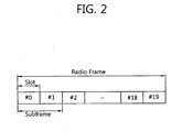
- FIG. 2 shows a structure of a radio frame in 3GPP LTE.
- the radio frame includes 10 subframes.
- One subframe includes two slots.
- a time for transmitting one subframe is defined as a transmission time interval (TTI).
- TTI transmission time interval
- one subframe may have a length of 1 millisecond (ms)
- one slot may have a length of 0.5 ms.
- One slot includes a plurality of SC-FDMA symbols (e.g., 7 SC-FDMA symbols) in a time domain and a plurality of resource blocks (RBs) in a frequency domain.
- the SC-FDMA symbol represents one symbol period.
- the SC-FDMA symbol can also be referred to as an OFDMA symbol or a symbol period.
- the RB is a resource allocation unit, and includes a plurality of contiguous subcarriers in one slot.
- the structure of the radio frame is shown for exemplary purposes only.
- the number of subframes included in the radio frame or the number of slots included in the subframe or the number of SC-FDMA symbols included in the slot may be modified in various manners.
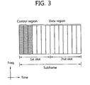
- FIG. 3 shows an exemplary structure of a downlink subframe.
- the subframe includes two consecutive slots.
- a maximum of three OFDM symbols located in a front portion of a 1 st slot within the downlink subframe correspond to a control region to be assigned with a physical downlink control channel (PDCCH).
- the remaining OFDM symbols correspond to a data region to be assigned with a physical downlink shared chancel (PDSCH).
- a physical control format indicator channel (PCFICH) is transmitted on a 1st OFDM symbol of the subframe and carries information regarding the number of OFDM symbols used for transmission of PDCCHs in the subframe.
- PCFICH physical control format indicator channel
- the PDCCH carries a downlink grant that reports resource allocation of downlink transmission on the PDSCH. More specifically, the PDCCH can carry a transmission format and resource allocation of a downlink shared channel (DL-SCH), paging information on a paging channel (PCH), system information on the DL-SCH, resource allocation of a high-level control message such as a random access response transmitted on the PDSCH, a transmit power control command, activation of a voice over Internet protocol (VoIP), etc. Further, the PDCCH can carry an uplink grant that reports resource allocation of uplink transmission to the UE.
- the PCFICH reports to the UE the number of OFDM symbols used for the PDCCHs, and is transmitted in every subframe.
- a physical hybrid ARQ indicator channel (PHICH) is a response of uplink transmission and carries an HARQ acknowledgment (ACK)/not-acknowledgment (NACK) signal.
- PHICH physical hybrid ARQ indicator channel
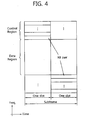
- FIG. 4 shows a structure of an uplink subframe in 3GPP LTE.
- the uplink subframe can be divided in a frequency domain into a control region and a data region.
- the control region is allocated with a physical uplink control channel (PUCCH) for carrying uplink control information.
- the data region is allocated with a physical uplink shared channel (PUSCH) for carrying user data.
- PUCCH physical uplink control channel
- PUSCH physical uplink shared channel
- the PUCCH for one UE is allocated to an RB pair in a subframe. RBs belonging to the RB pair occupy different subcarriers in respective two slots. This is called that the RB pair allocated to the PUCCH is frequency-hopped in a slot boundary.
- FIG. 5 shows uplink HARQ and CQI transmission.
- a BS upon receiving uplink data 100 on a PDSCH from a UE, a BS transmits an ACK/NACK signal 101 for the uplink data 100 on a PHICH after a specific time elapses.
- the BS may transmit the PHICH after a time corresponding to 4 TTIs elapses.
- the present invention is not limited thereto. If the uplink data is successfully decoded, the ACK/NACK signal 101 is an ACK signal. If the uplink data is unsuccessfully decoded, the ACK/NACK signal 101 is a NACK signal.
- retransmission data 110 for the uplink data 100 is retransmitted to the BS. Retransmission may be performed until the ACK signal is received or may be performed up to the number of times corresponding to the number of retransmission attempts.
- an ACK/NACK signal 111 for the retransmission data 110 is determined to be the ACK signal, the UE can transmit new uplink data 120 to the BS.
- Resource allocation or a transmission time point of an ACK/NACK signal for uplink/downlink data may be dynamically reported by the BS through signaling, or may be predetermined according to resource allocation or a transmission time point of the uplink/downlink data.
- the UE can report a CQI to the BS periodically and/or non-periodically by measuring a downlink channel state.
- the CQI When the CQI is reported periodically, it implies that the CQI is transmitted without receiving an additional request from the BS according to a predetermined period or a period determined by the BS.
- the CQI When the CQI is reported non-periodically, it implies that the CQI is transmitted in response to a request from the BS.
- the CQI may be transmitted on a PUCCH or a PUSCH.
- the CQI is multiplexed together with data, the CQI is transmitted always on the PUSCH.
- CQIs 180 and 184 are transmitted alone and may be transmitted on the PUCCH or the PUSCH.
- a CQI 182 is transmitted together with uplink data and may be transmitted only on the PUSCH.
- the CQI transmitted on the PUSCH may be a periodic CQI or a non-periodic CQI.
- the BS may use the CQI to perform downlink scheduling.
- uplink HARQ will be described.
- the technical features of the present invention will be easily applied to downlink HARQ by a person of ordinary skill in the art.
- FIG. 6 shows dynamic scheduling in uplink transmission.
- a UE transmits a scheduling request (SR) to a BS on a PUCCH.
- the SR is used when the UE requests the BS to allocate uplink radio resources.
- the SR is a sort of preliminary information exchange for data exchange.
- radio resource allocation is first requested by using the SR.
- the BS transmits an uplink grant to the UE on a PDCCH.
- the uplink grant includes allocation of the uplink radio resources.
- the UE transmits the uplink data on the PUSCH by using the allocated uplink radio resources.
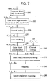
- FIG. 7 is an exemplary diagram showing multiplexing of data and control information on a PUSCH.
- the PUSCH carries data and/or control information through an allocation resource by using an uplink grant.
- data bits a 0 , a 1 , ..., a A-1 are provided for each TTI in a format of one transport block.
- CRC cyclic redundancy check
- parity bits p 0 , p 1 , ..., p L-1 are attached to the data bits a 0 , a 1 , ..., a A-1 to generate CRC-attached bits b 0 , b 1 , ..., b B-1 (step 200).
- B A+L.
- Equation 1 below shows a relationship between a k and b k .
- the CRC-attached bits b 0 , b 1 , ..., b B-1 are segmented in a code block unit, and the CRC parity bits are re-attached in the code block unit (step 210).
- c r0 , c r1 , ..., c r(Kr-1) denote a bit sequence output after the code block segmentation.
- r denotes a code block number
- Kr denotes the number of bits for the code block number r.
- Channel coding is performed on a bit sequence for a given code block (step 220).
- d (i) 0 , d (i) 1 , ..., d (i) D-1 denote encoded bits, D denotes the number of encoded bits for each output stream, and i denotes an index of a bit stream output from an encoder.
- Rate matching is performed on the encoded bits (step 230). Then, code block concatenation is performed on the rate-matched bits (step 240). As a result, a data bit sequence f 0 , f 1 ,..., f G-1 is generated.
- G denotes a total number of encoded bits used to transmit bits other than bits that is used in control information transmission when the control information is multiplexed on a PUSCH.
- the control information can be multiplexed together with data.
- the data and the control information can use different coding rates by allocating a different number of coded symbols for transmission thereof.
- a CQI is considered as the control information.
- Channel coding is performed on CQI values o 0 , o 1 , ..., o 0-1 (where O is the number of CQI bits) to generate a control information bit sequence q 0 , q 1 , ..., q Q-1 (step 260).
- the CQI can use independent channel coding different from that used for the data. For example, when a block code (32, O) is used as channel coding for the CQI, a basis sequence M i,n is as shown in Table 1 below.
- b 0 , b 1 , ..., b 31 denote an intermediate sequence for CQI channel coding and can be generated by Equation 2 below.
- the control information bit sequence q 0 , q 1 , ..., q Q-1 is generated by cyclically repeating the intermediate sequence b 0 , b 1 , ..., b 31 according to Equation 3 below.
- a data bit sequence f 0 , f 1 ,..., f G-1 is generated as described above and is multiplexed together with the control information bit sequence q 0 , q 1 , ... , q Q-1 into a multiplexed sequence g 0 , g 1 , ... , g H-1 (step 270).
- the control information bit sequence q 0 , q 1 , ..., q Q-1 can be arranged first and thereafter the data bit sequence f 0 , f 1 ,..., f G-1 can be arranged.
- [g 0 , g 1 , ..., g H-1 ] may be configured such as [q 0 , q 1 , ..., q Q-1 , f 0 , f 1 ,..., f G-1 ].
- the multiplexed sequence g 0 , g 1 , ..., g H-1 is mapped to a modulation sequence h 0 , h 1 , ..., h H'-1 (step 280).
- h i denotes a modulation symbol on constellation
- H' H/Q m
- Each modulation symbol of the modulation sequence h 0 , h 1 , ..., h H'-1 is mapped to a resource element for the PUSCH (step 290).
- the resource element is a unit of allocation on a subframe defined with one SC-FDMA symbol (or OFDMA symbol) and one subcarrier.
- the modulation symbols are mapped in a time-first manner.
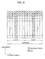
- FIG. 8 shows resource mapping on a PUSCH.
- One slot includes 7 SC-FDMA symbols. In each slot, a 4 th SC-FDMA symbol is used to transmit a reference signal. Therefore, up to 12 SC-FDMA symbols can be used for the PUSCH in one subframe.
- a modulation sequence h 0 , h 1 , ..., h H'-1 is first mapped in a 1 st subcarrier region in an SC-FDMA symbol direction, and is then mapped in a 2 nd subcarrier region also in the SC-FDMA symbol direction.
- a front portion of the modulation sequence h 0 , h 1 , ..., h H'-1 corresponds to a CQI.
- the CQI is first mapped to resource elements in a front subcarrier region.
- an amount of resources required to transmit the CQI needs to be determined first.
- the amount of resources is determined based on a transmission parameter (e.g., MCS, etc.) used in CQI transmission.
- the transmission parameter for the CQI denotes a parameter used for CQI transmission, and includes various parameters for determining the MCS and/or the amount of resources. If the amount of resources is expressed by the number Q' of modulation symbols for the CQI, Q' can be determined by Equation 4 below.
- Equation 4 O denotes the number of CQI bits, L denotes the number of CRC bits, ⁇ denotes a parameter, C denotes a total number of code blocks, K r denotes the number of bits for a code block number r, M sc denotes the number of subcarriers used in PUSCH transmission, and N symb denotes the number of SC-FDMA symbols used in PUSCH transmission.
- Transmission parameters for determining the aforementioned Q' may be at least one of C, K r , M sc , and N symb .
- the CQI may be transmitted by being multiplexed with initial data or retransmission data. This may occur when a CQI transmission period coincides with a retransmission period in periodic CQI reporting or when a response for a CQI transmission request coincides with the retransmission period in non-periodic CQI reporting.
- the CQI When the CQI is multiplexed with the retransmission data, there is an issue as to how transmission parameters (e.g., MCS, etc.) for the CQI are determined.
- the issue is related to how to determine the transmission parameters used for the CQI multiplexed with the retransmission data. This is because, when the transmission parameters for CQI transmission have to be additionally reported by the BS to the UE even at retransmission, the reporting of the transmission parameters may act as a signaling overhead.
- a CQI transmission parameter can be determined according to the transmission parameters used in initial data transmission. For example, an MCS used in initial data transmission is used for CQI transmission when the data is retransmitted.
- FIG. 9 is a flow diagram showing an HARQ method.
- a BS transmits an initial uplink grant on a PDCCH.
- the initial uplink grant includes radio resource allocation information for initial uplink data in the HARQ method.
- a UE transmits uplink data on a PUSCH indicated by the initial uplink grant.
- step S530 upon detecting a decoding error of the uplink data, the BS transmits a NACK signal as a retransmission request.
- the NACK signal may be transmitted on a PHICH.
- step S560 if a transmission subframe of retransmission data coincides with a transmission subframe of a CQI, the UE determines a transmission parameter of the CQI from the initial uplink grant.
- the transmission parameter is a parameter for determining an amount of radio resources required to transmit the CQI, and may be related to an MCS of the CQI. For example, when the amount of radio resources of the CQI is determined by Equation 4, at least one of transmission parameters C, K r , M sc , and N symb can be obtained from the initial uplink grant.
- step S570 the UE multiplexes the CQI and the retransmission data of the uplink data by using the transmission parameter.
- step S580 the UE transmits the multiplexed data on the PUSCH.
- the MCS of the CQI is determined according to the initial uplink grant, so that a signaling overhead can be reduced without additional signaling for the transmission parameter of the CQI to be multiplexed.
- FIG. 10 is a flow diagram showing an HARQ method according to the embodiment of the present invention.
- a BS transmits an initial uplink grant on a PDCCH.
- a UE transmits uplink data on a PUSCH indicated by the initial uplink grant.
- the BS upon detecting a decoding error of the uplink data, the BS transmits a NACK signal as a retransmission request.
- step S640 the BS transmits a retransmission grant on the PDCCH.
- the retransmission grant includes radio resource allocation information for retransmission data regarding the uplink data.
- step s650 if a transmission subframe of retransmission data coincides with a transmission subframe of a CQI, the UE determines a transmission parameter of the CQI from the initial uplink grant.
- step S670 the UE multiplexes the CQI and the retransmission of the uplink data by using the transmission parameter.
- the retransmission data is multiplexed using a transmission parameter obtained from the retransmission grant
- the CQI is multiplexed using a transmission parameter obtained from the initial grant.
- step S680 the UE transmits the multiplexed data on the PUSCH.
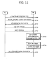
- FIG. 11 is a flow diagram showing an HARQ method.
- a BS configures a periodic CQI.
- a UE periodically transmits the CQI according to a period determined by the BS.
- the BS transmits an initial uplink grant on a PDCCH.
- the initial uplink grant includes radio resource allocation information for initial uplink data in the HARQ method.
- the UE transmits uplink data on a PUSCH indicated by the initial uplink grant.
- step S730 the UE transmits the CQI at a CQI transmission period.
- the CQI can be transmitted on a PUCCH.
- step S740 upon detecting a decoding error of the uplink data, the BS transmits a NACK signal as a retransmission request.
- step S760 if a transmission subframe of retransmission data coincides with a transmission subframe of a CQI, the UE determines a transmission parameter of the CQI from the initial uplink grant.
- step S770 the UE multiplexes the CQI and the retransmission data of the uplink data by using the transmission parameter.
- step S780 the UE transmits the multiplexed data on the PUSCH.
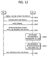
- FIG. 12 is a flow diagram showing an HARQ method.
- a BS transmits an initial uplink grant on a PDCCH.
- a UE transmits uplink data on a PUSCH indicated by the initial uplink grant.
- the BS upon detecting a decoding error of the uplink data, transmits a NACK signal as a retransmission request.
- the BS transmits a retransmission grant and a CQI request on the PDCCH.
- the CQI request is a signal optionally used by the BS to request the UE to transmit the CQI.
- the CQI request is transmitted on the PDCCH together with the retransmission grant, the CQI request can be transmitted to the UE through an additional message.
- step S860 the UE determines a transmission parameter of the CQI from the initial uplink grant according to the CQI request of the BS.
- step S870 the UE multiplexes the CQI and the retransmission of the uplink data by using the transmission parameter.
- the retransmission data is multiplexed using a transmission parameter obtained from the retransmission grant
- the CQI is multiplexed using a transmission parameter obtained from the initial grant.
- step S880 the UE transmits the multiplexed data on the PUSCH.
- the CQI transmission parameter can be obtained from the initial uplink grant even if the CQI is transmitted by being multiplexed at n-th retransmission (where n>1).
- a non-periodic CQI is transmitted at the request of the BS.
- the CQI request can be transmitted on the PDCCH.
- a transmission indicator for the CQI transmission parameter can be transmitted along with the CQI request.
- the CQI may be transmitted using an allocated resource (or transmission parameter) according to the transmission indicator, or the CQI may be transmitted using a previously allocated resource (or transmission parameter).
- FIG. 13 is a block diagram showing an apparatus for wireless communication according to an embodiment of the present invention.
- An apparatus 50 for wireless communication may be a part of a UE.
- the apparatus 50 for wireless communication includes a processor 51, a memory 52, a radio frequency (RF) unit 53, a display unit 54, and a user interface unit 55.
- the RF unit 53 is coupled to the processor 51 and transmits and/or receives radio signals.
- the memory 52 is coupled to the processor 51 and stores an operating system, applications, and general files.
- the display unit 54 displays a variety of information of the UE and may use a well-known element such as a liquid crystal display (LCD), an organic light emitting diode (OLED), etc.
- LCD liquid crystal display
- OLED organic light emitting diode
- the user interface unit 55 can be configured with a combination of well-known user interfaces such as a keypad, a touch screen, etc.
- the processor 51 supports HARQ and AMC.
- the processor 51 can configure a PUCCH or a PUSCH and can perform multiplexing of data and a CQI.
- the aforementioned embodiments of the HARQ method can be implemented by the processor 51.
- the present invention can be implemented with hardware, software, or combination thereof.
- the present invention can be implemented with one of an application specific integrated circuit (ASIC), a digital signal processor (DSP), a programmable logic device (PLD), a field programmable gate array (FPGA), a processor, a controller, a microprocessor, other electronic units, and combination thereof, which are designed to perform the aforementioned functions.
- ASIC application specific integrated circuit
- DSP digital signal processor
- PLD programmable logic device
- FPGA field programmable gate array
- the present invention can be implemented with a module for performing the aforementioned functions.
- Software is storable in a memory unit and executed by the processor.
- Various means widely known to those skilled in the art can be used as the memory unit or the processor.
Description
- The present invention relates to wireless communications, and more particularly, to a method and apparatus for supporting hybrid automatic repeat request (HARQ) in a wireless communication system.
- Wireless communication systems are widely spread all over the world to provide various types of communication services such as voice or data. In general, the wireless communication system is a multiple access system capable of supporting communication with multiple users by sharing available system resources (e.g., bandwidth, transmission power, etc.). Examples of the multiple access system include a code division multiple access (CDMA) system, a frequency division multiple access (FDMA) system, a time division multiple access (TDMA) system, an orthogonal frequency division multiple access (OFDMA) system, a single carrier frequency division multiple access (SC-FDMA) system, etc.
- Current development in advanced wireless communication has led to the requirement of high spectral efficiency and reliable communication. Unfortunately, packet errors by fading channel environment and interferences originated from various sources make the capacity of overall system to be limited.
- Hybrid automatic repeat request (HARQ) is an ARQ protocol combined with forward error correction (FEC) and is strongly considered as one of cutting edge technologies for future reliable communication. The HARQ scheme can largely be classified into two types. One is HARQ-chase combining (CC) which is disclosed in D. Chase, Code Combining: A maximum-likelihood decoding approach for combining an arbitrary number of noisy packets, IEEE Trans. on Commun., Vol. 33, pp. 593-607, May 1985. The other is HARQ-Increment Redundancy (IR). In the HARQ-CC, when a receiver detects an error through cyclic redundancy checking (CRC) while decoding the transmitted packet, the same packet with the same modulation and coding is retransmitted to the receiver. Meanwhile, in order to achieve a coding gain, the HARQ-IR retransmits different packets, in which parity bits can be manipulated through puncturing and repetition. To perform the HARQ, there is a need to exchange acknowledgement (ACK)/not-acknowledgement (NACK) information that indicates whether retransmission is necessary.
- Adaptive modulation and coding (AMC) is also a technology for providing reliable communication. A base station (BS) determines a modulation and coding scheme (MCS) used for transmission by using a channel quality indicator (CQI) received from a user equipment (UE). In general, the CQI is an index of an entity of an MCS table showing a plurality of MCSs. The UE transmits the CQI by using two methods. One is that the CQI is transmitted periodically. The other is that the CQI is transmitted at the request of the BS.
- 3rd generation partnership project (3GPP) long term evolution (LTE) is a part of an evolved-universal mobile telecommunications system (E-UMTS) using evolved-universal terrestrial radio access (E-UTRA), and adopts the OFDMA in downlink and the SC-FDMA in uplink. Resource allocation of the 3GPP LTE is based on dynamic scheduling. A downlink physical channel of the 3GPP LTE can be divided into a physical downlink control channel (PDCCH) for carrying resource allocation information and a physical downlink shared channel (PDSCH) for carrying downlink data. An uplink physical channel can be divided into a physical uplink control channel (PUCCH) for carrying uplink control information and a physical uplink shared channel (PUSCH) for carrying uplink data. In downlink transmission, the UE first receives a downlink grant on the PDCCH, and then receives downlink data on the PDSCH indicated by the downlink grant. In uplink transmission, the UE receives an uplink grant on the PDCCH, and then transmits uplink data on the PUSCH indicated by the uplink grant. Dynamic scheduling is a method capable of effective resource allocation. However, the UE always has to receive the downlink/uplink grant first to transmit and/or receive data.
- A signaling overhead is a major cause of low transmission efficiency and low frequency efficiency. In dynamic scheduling, in addition to reception of the PDCCH, the HARQ operation and the CQI transmission are carried out by using a plurality of signaling operations such as exchange of ACK/NACK information, exchange of a transmission parameter for the CQI, etc.
- Accordingly, there is a need for a method capable of reducing a signaling overhead caused by CQI transmission in a process of performing HARQ.
- ALCATEL-LUCENT (3 GPP DRAFT; R1 080912_POWEROFFSETSCONTROLMUX, 3RD GENERATION PARTNERSHIP PROJECT (3GPP), MOBILE COMPETENCE CENTRE; 6 February 2008, XP050109386) describes power offsets to support data and control multiplexing for persistent PUSCH. When non-data associated control information, such as ACK/NACK and/or CQI to support a downlink needs to be transmitted at the same time there is uplink data to transmit on the PUSCH, the non-data associated control information is multiplexed together with the data on PUSCH.
- The object of the present invention is solved by the features of the independent claims.
- The present invention provides a method of multiplexing and transmitting a channel quality indicator (CQI) and retransmission data.
- In an aspect, a method of supporting Hybrid Automatic Repeat Request (HARQ) in a wireless communication system is provided. The method preferably includes receiving an initial uplink grant on a downlink channel, transmitting uplink data on an uplink channel using the initial uplink grant, receiving a request for retransmission of the uplink data, determining at least one transmission parameter of a channel quality indicator (CQI) from the initial uplink grant, multiplexing retransmission data of the uplink data with the CQI, wherein an amount of resources for transmission of the CQI is determined based on the at least one transmission parameter, and transmitting the multiplexed data on the uplink channel.
- The method further includes receiving a retransmission uplink grant for retransmission of the uplink data, wherein the retransmission data of the uplink data is multiplexed by using the retransmission uplink grant. A request for reporting the CQI may be included in the retransmission uplink grant.
- The retransmission data of the uplink data may be multiplexed by using the initial uplink grant. The downlink channel may be a Physical Downlink Control Channel (PDCCH) and the uplink channel may be a Physical Uplink Shared Channel (PUSCH).
- The at least one transmission parameter of the CQI may be related to a Modulation and Coding Scheme (MCS) of the CQI.
- In another aspect, an apparatus for wireless communication is provided. The apparatus preferably includes a Radio Frequency (RF) unit for transmitting and receiving a radio signal, and a processor coupled with the RF unit and configured to receive an initial uplink grant on a downlink channel, determine at least one transmission parameter from the initial uplink grant, transmit uplink data on an uplink channel using the at least one transmission parameter, receive a request for retransmission of the uplink data, receive a retransmission uplink grant on the downlink channel, multiplex retransmission data of the uplink data with a CQI, wherein an amount of resources for transmission of the CQI is determined based on the at least one transmission parameter used for the transmission of the initial uplink data, wherein an amount of resources for transmission of the retransmission data is determined based on radio resource allocation information included in the retransmission uplink grant, and transmit the multiplexed data on the uplink channel.
- A method of transmitting retransmission data together with a channel quality indicator (CQI) in a process of performing hybrid automatic repeat request (HARQ) is proposed. Accordingly, HARQ and adaptive modulation and coding (AMC) operations can be accurately performed, and a signaling overhead can be reduced.
-
-
FIG. 1 shows a wireless communication system. -
FIG. 2 shows a structure of a radio frame in 3rd generation partnership project (3GPP) long term evolution (LTE). -
FIG. 3 shows an exemplary structure of a downlink subframe. -
FIG. 4 shows a structure of an uplink subframe in 3GPP LTE. -
FIG. 5 shows uplink hybrid automatic repeat request (HARQ) and channel quality indicator (CQI) transmission. -
FIG. 6 shows dynamic scheduling in uplink transmission. -
FIG. 7 is an exemplary diagram showing multiplexing of data and control information on a physical uplink shared channel (PUSCH). -
FIG. 8 shows resource mapping on a PUSCH. -
FIG. 9 is a flow diagram showing an HARQ method. -
FIG. 10 is a flow diagram showing an HARQ method according to another embodiment of the present invention. -
FIG. 11 is a flow diagram showing an HARQ method. -
FIG. 12 is a flow diagram showing an HARQ method. -
FIG. 13 is a block diagram showing an apparatus for wireless communication according to an embodiment of the present invention. - The techniques described herein can be used in various wireless communication systems such as code division multiple access (CDMA), frequency division multiple access (FDMA), time division multiple access (TDMA), orthogonal frequency division multiple access (OFDMA), single carrier frequency division multiple access (SC-FDMA), etc. The CDMA can be implemented with a radio technology such as universal terrestrial radio access (UTRA) or CDMA-2000. The TDMA can be implemented with a radio technology such as global system for mobile communications (GSM)/general packet ratio service (GPRS)/enhanced data rate for GSM evolution (EDGE). The OFDMA can be implemented with a radio technology such as institute of electrical and electronics engineers (IEEE) 802.11 (Wi-Fi), IEEE 802.16 (WiMAX), IEEE 802.20, evolved UTRA (E-UTRA), etc. The UTRA is a part of a universal mobile telecommunication system (UMTS). 3rd generation partnership project (3GPP) long term evolution (LTE) is a part of an evolved UMTS (E-UMTS) using the E-UTRA. The 3GPP LTE uses the OFDMA in downlink and uses the SC-FDMA in uplink.
- For clarity, the following description will focus on the 3GPP LTE. However, the technical features of the present invention are not limited thereto.
-
FIG. 1 shows a wireless communication system. - Referring to
FIG. 1 , awireless communication system 10 includes at least one base station (BS) 11. TheBSs 11 provide communication services to specific geographical regions (generally referred to as cells) 15a, 15b, and 15c. The cell can be divided into a plurality of regions (referred to as sectors). A user equipment (UE) 12 may be fixed or mobile, and may be referred to as another terminology, such as a mobile station (MS), a user terminal (UT), a subscriber station (SS), a wireless device, a personal digital assistant (PDA), a wireless modem, a handheld device, etc. TheBS 11 is generally a fixed station that communicates with theUE 12 and may be referred to as another terminology, such as an evolved node-B (eNB), a base transceiver system (BTS), an access point, etc. - Hereinafter, downlink (DL) denotes a communication link from the BS to the UE, and uplink (UL) denotes a communication link from the UE to the BS. In the DL, a transmitter may be a part of the BS, and a receiver may be a part of the UE. In the UL, the transmitter may be a part of the UE, and the receiver may be a part of the BS.
- The wireless communication system can support uplink and/or downlink hybrid automatic repeat request (HARQ). In addition, a channel quality indicator (CQI) can be used to support adaptive modulation and coding (AMC).
- The CQI indicates a downlink channel state and may include a CQI index and/or a precoding matrix index (PMI). The CQI index indicates each entity of a modulation and coding scheme (MCS) table including a plurality of entities configured by combining coding rates and modulation schemes. The PMI is an index of a precoding matrix based on a codebook. The CQI may indicate a channel state for a full band and/or a channel state for some bands included in the full band.
-
FIG. 2 shows a structure of a radio frame in 3GPP LTE. The radio frame includes 10 subframes. One subframe includes two slots. A time for transmitting one subframe is defined as a transmission time interval (TTI). For example, one subframe may have a length of 1 millisecond (ms), and one slot may have a length of 0.5 ms. One slot includes a plurality of SC-FDMA symbols (e.g., 7 SC-FDMA symbols) in a time domain and a plurality of resource blocks (RBs) in a frequency domain. In the 3GPP LTE using the SC-FDMA symbol in uplink, the SC-FDMA symbol represents one symbol period. According to a system, the SC-FDMA symbol can also be referred to as an OFDMA symbol or a symbol period. The RB is a resource allocation unit, and includes a plurality of contiguous subcarriers in one slot. - The structure of the radio frame is shown for exemplary purposes only. Thus, the number of subframes included in the radio frame or the number of slots included in the subframe or the number of SC-FDMA symbols included in the slot may be modified in various manners.
-
FIG. 3 shows an exemplary structure of a downlink subframe. The subframe includes two consecutive slots. A maximum of three OFDM symbols located in a front portion of a 1st slot within the downlink subframe correspond to a control region to be assigned with a physical downlink control channel (PDCCH). The remaining OFDM symbols correspond to a data region to be assigned with a physical downlink shared chancel (PDSCH). A physical control format indicator channel (PCFICH) is transmitted on a 1st OFDM symbol of the subframe and carries information regarding the number of OFDM symbols used for transmission of PDCCHs in the subframe. - The PDCCH carries a downlink grant that reports resource allocation of downlink transmission on the PDSCH. More specifically, the PDCCH can carry a transmission format and resource allocation of a downlink shared channel (DL-SCH), paging information on a paging channel (PCH), system information on the DL-SCH, resource allocation of a high-level control message such as a random access response transmitted on the PDSCH, a transmit power control command, activation of a voice over Internet protocol (VoIP), etc. Further, the PDCCH can carry an uplink grant that reports resource allocation of uplink transmission to the UE. The PCFICH reports to the UE the number of OFDM symbols used for the PDCCHs, and is transmitted in every subframe. A physical hybrid ARQ indicator channel (PHICH) is a response of uplink transmission and carries an HARQ acknowledgment (ACK)/not-acknowledgment (NACK) signal.
-
FIG. 4 shows a structure of an uplink subframe in 3GPP LTE. - Referring to
FIG. 4 , the uplink subframe can be divided in a frequency domain into a control region and a data region. The control region is allocated with a physical uplink control channel (PUCCH) for carrying uplink control information. The data region is allocated with a physical uplink shared channel (PUSCH) for carrying user data. To maintain a single carrier property, one UE does not simultaneously transmit the PUCCH and the PUSCH. - The PUCCH for one UE is allocated to an RB pair in a subframe. RBs belonging to the RB pair occupy different subcarriers in respective two slots. This is called that the RB pair allocated to the PUCCH is frequency-hopped in a slot boundary.
-
FIG. 5 shows uplink HARQ and CQI transmission. - Referring to
FIG. 5 , upon receivinguplink data 100 on a PDSCH from a UE, a BS transmits an ACK/NACK signal 101 for theuplink data 100 on a PHICH after a specific time elapses. When theuplink data 100 is received, the BS may transmit the PHICH after a time corresponding to 4 TTIs elapses. However, the present invention is not limited thereto. If the uplink data is successfully decoded, the ACK/NACK signal 101 is an ACK signal. If the uplink data is unsuccessfully decoded, the ACK/NACK signal 101 is a NACK signal. When the ACK/NACK signal 101 is determined to be the NACK signal,retransmission data 110 for theuplink data 100 is retransmitted to the BS. Retransmission may be performed until the ACK signal is received or may be performed up to the number of times corresponding to the number of retransmission attempts. When an ACK/NACK signal 111 for theretransmission data 110 is determined to be the ACK signal, the UE can transmitnew uplink data 120 to the BS. - Resource allocation or a transmission time point of an ACK/NACK signal for uplink/downlink data may be dynamically reported by the BS through signaling, or may be predetermined according to resource allocation or a transmission time point of the uplink/downlink data.
- The UE can report a CQI to the BS periodically and/or non-periodically by measuring a downlink channel state. When the CQI is reported periodically, it implies that the CQI is transmitted without receiving an additional request from the BS according to a predetermined period or a period determined by the BS. When the CQI is reported non-periodically, it implies that the CQI is transmitted in response to a request from the BS. The CQI may be transmitted on a PUCCH or a PUSCH. When the CQI is multiplexed together with data, the CQI is transmitted always on the PUSCH.
CQIs CQI 182 is transmitted together with uplink data and may be transmitted only on the PUSCH. The CQI transmitted on the PUSCH may be a periodic CQI or a non-periodic CQI. The BS may use the CQI to perform downlink scheduling. - In the following description, uplink HARQ will be described. However, the technical features of the present invention will be easily applied to downlink HARQ by a person of ordinary skill in the art.
-
FIG. 6 shows dynamic scheduling in uplink transmission. - Referring to
FIG. 6 , for uplink transmission, a UE transmits a scheduling request (SR) to a BS on a PUCCH. The SR is used when the UE requests the BS to allocate uplink radio resources. The SR is a sort of preliminary information exchange for data exchange. In order for the UE to transmit uplink data to the BS, radio resource allocation is first requested by using the SR. In response to the SR, the BS transmits an uplink grant to the UE on a PDCCH. The uplink grant includes allocation of the uplink radio resources. The UE transmits the uplink data on the PUSCH by using the allocated uplink radio resources. -
FIG. 7 is an exemplary diagram showing multiplexing of data and control information on a PUSCH. The PUSCH carries data and/or control information through an allocation resource by using an uplink grant. - Referring to
FIG. 7 , data bits a0, a1, ..., aA-1 are provided for each TTI in a format of one transport block. First, cyclic redundancy check (CRC) parity bits p0, p1, ..., pL-1 are attached to the data bits a0, a1, ..., aA-1 to generate CRC-attached bits b0, b1, ..., bB-1 (step 200). Herein, B=A+L. Equation 1 below shows a relationship between ak and bk.
- The CRC-attached bits b0, b1, ..., bB-1 are segmented in a code block unit, and the CRC parity bits are re-attached in the code block unit (step 210). cr0, cr1, ..., cr(Kr-1) denote a bit sequence output after the code block segmentation. Herein, if a total number of code blocks is C, r denotes a code block number, and Kr denotes the number of bits for the code block number r.
- Channel coding is performed on a bit sequence for a given code block (step 220). d(i) 0, d(i) 1, ..., d(i) D-1 denote encoded bits, D denotes the number of encoded bits for each output stream, and i denotes an index of a bit stream output from an encoder.
- Rate matching is performed on the encoded bits (step 230). Then, code block concatenation is performed on the rate-matched bits (step 240). As a result, a data bit sequence f0, f1,..., fG-1 is generated. Herein, G denotes a total number of encoded bits used to transmit bits other than bits that is used in control information transmission when the control information is multiplexed on a PUSCH.
- The control information can be multiplexed together with data. The data and the control information can use different coding rates by allocating a different number of coded symbols for transmission thereof. Hereinafter, a CQI is considered as the control information.
- Channel coding is performed on CQI values o0, o1, ..., o0-1 (where O is the number of CQI bits) to generate a control information bit sequence q0, q1, ..., qQ-1 (step 260). The CQI can use independent channel coding different from that used for the data. For example, when a block code (32, O) is used as channel coding for the CQI, a basis sequence Mi,n is as shown in Table 1 below.
[Table 1] i Mi,0 Mi,1 Mi,2 Mi,3 Mi,4 Mi,5 Mi,6 Mi,7 Mi,8 Mi,9 Mi,10 0 1 1 0 0 0 0 0 0 0 0 1 1 1 1 1 0 0 0 0 0 0 1 1 2 1 0 0 1 0 0 1 0 1 1 1 3 1 0 1 1 0 0 0 0 1 0 1 4 1 1 1 1 0 0 0 1 0 0 1 5 1 1 0 0 1 0 1 1 1 0 1 6 1 0 1 0 1 0 1 0 1 1 1 7 1 0 0 1 1 0 0 1 1 0 1 8 1 1 0 1 1 0 0 1 0 1 1 9 1 0 1 1 1 0 1 0 0 1 1 10 1 0 1 0 0 1 1 1 0 1 1 11 1 1 1 0 0 1 1 0 1 0 1 12 1 0 0 1 0 1 0 1 1 1 1 13 1 1 0 1 0 1 0 1 0 1 1 14 1 0 0 0 1 1 0 1 0 0 1 15 1 1 0 0 1 1 1 1 0 1 1 16 1 1 1 0 1 1 1 0 0 1 0 17 1 0 0 1 1 1 0 0 1 0 0 18 1 1 0 1 1 1 1 1 0 0 0 19 1 0 0 0 1 1 0 0 0 0 0 20 1 0 1 0 0 0 1 0 0 0 1 21 1 1 0 1 0 0 0 0 0 1 1 22 1 0 0 0 1 0 0 1 1 0 1 23 1 1 1 0 1 0 0 0 1 1 1 24 1 1 1 1 1 0 1 1 1 1 0 25 1 1 0 0 0 1 1 1 0 0 1 26 1 0 1 1 0 1 0 0 1 1 0 27 1 1 1 1 0 1 0 1 1 1 0 28 1 0 1 0 1 1 1 0 1 0 0 29 1 0 1 1 1 1 1 1 1 0 0 30 1 1 1 1 1 1 1 1 1 1 1 31 1 0 0 0 0 0 0 0 0 0 0 - b0, b1, ..., b31 denote an intermediate sequence for CQI channel coding and can be generated by
Equation 2 below.
- The control information bit sequence q0, q1, ..., qQ-1 is generated by cyclically repeating the intermediate sequence b0, b1, ..., b31 according to
Equation 3 below.
- A data bit sequence f0, f1,..., fG-1 is generated as described above and is multiplexed together with the control information bit sequence q0, q1, ... , qQ-1 into a multiplexed sequence g0, g1, ... , gH-1 (step 270). In a process of multiplexing, the control information bit sequence q0, q1, ..., qQ-1 can be arranged first and thereafter the data bit sequence f0, f1,..., fG-1 can be arranged. That is, if H=G+Q, [g0, g1, ..., gH-1] may be configured such as [q0, q1, ..., qQ-1, f0, f1,..., fG-1].
- The multiplexed sequence g0, g1, ..., gH-1 is mapped to a modulation sequence h0, h1, ..., hH'-1 (step 280). Herein, hi denotes a modulation symbol on constellation, and H'=H/Qm. Qm denotes the number of bits for each modulation symbol of a modulation scheme. For example, when quadrature phase shift keying (QPSK) is used as the modulation scheme, Qm=2.
- Each modulation symbol of the modulation sequence h0, h1, ..., hH'-1 is mapped to a resource element for the PUSCH (step 290). The resource element is a unit of allocation on a subframe defined with one SC-FDMA symbol (or OFDMA symbol) and one subcarrier. The modulation symbols are mapped in a time-first manner.
FIG. 8 shows resource mapping on a PUSCH. One slot includes 7 SC-FDMA symbols. In each slot, a 4th SC-FDMA symbol is used to transmit a reference signal. Therefore, up to 12 SC-FDMA symbols can be used for the PUSCH in one subframe. A modulation sequence h0, h1, ..., hH'-1 is first mapped in a 1st subcarrier region in an SC-FDMA symbol direction, and is then mapped in a 2nd subcarrier region also in the SC-FDMA symbol direction. A front portion of the modulation sequence h0, h1, ..., hH'-1 corresponds to a CQI. Thus, the CQI is first mapped to resource elements in a front subcarrier region. - As described above, to transmit the CQI on the PUSCH, an amount of resources required to transmit the CQI needs to be determined first. The amount of resources is determined based on a transmission parameter (e.g., MCS, etc.) used in CQI transmission. The transmission parameter for the CQI denotes a parameter used for CQI transmission, and includes various parameters for determining the MCS and/or the amount of resources. If the amount of resources is expressed by the number Q' of modulation symbols for the CQI, Q' can be determined by
Equation 4 below.
- In
Equation 4, O denotes the number of CQI bits, L denotes the number of CRC bits, Δ denotes a parameter, C denotes a total number of code blocks, Kr denotes the number of bits for a code block number r, Msc denotes the number of subcarriers used in PUSCH transmission, and Nsymb denotes the number of SC-FDMA symbols used in PUSCH transmission. Transmission parameters for determining the aforementioned Q' may be at least one of C, Kr, Msc, and Nsymb. - Now, a method of multiplexing retransmission data and a CQI and transmitting the multiplexed result through a PUSCH in a process of performing HARQ will be described.
- When the HARQ is performed, the CQI may be transmitted by being multiplexed with initial data or retransmission data. This may occur when a CQI transmission period coincides with a retransmission period in periodic CQI reporting or when a response for a CQI transmission request coincides with the retransmission period in non-periodic CQI reporting.
- When the CQI is multiplexed with the retransmission data, there is an issue as to how transmission parameters (e.g., MCS, etc.) for the CQI are determined. The issue is related to how to determine the transmission parameters used for the CQI multiplexed with the retransmission data. This is because, when the transmission parameters for CQI transmission have to be additionally reported by the BS to the UE even at retransmission, the reporting of the transmission parameters may act as a signaling overhead.
- If the CQI is transmitted when the data is retransmitted, a CQI transmission parameter can be determined according to the transmission parameters used in initial data transmission. For example, an MCS used in initial data transmission is used for CQI transmission when the data is retransmitted.
-
FIG. 9 is a flow diagram showing an HARQ method. - Referring to
FIG. 9 , in step S510, a BS transmits an initial uplink grant on a PDCCH. The initial uplink grant includes radio resource allocation information for initial uplink data in the HARQ method. In step S520, a UE transmits uplink data on a PUSCH indicated by the initial uplink grant. - In step S530, upon detecting a decoding error of the uplink data, the BS transmits a NACK signal as a retransmission request. The NACK signal may be transmitted on a PHICH.
- In step S560, if a transmission subframe of retransmission data coincides with a transmission subframe of a CQI, the UE determines a transmission parameter of the CQI from the initial uplink grant. The transmission parameter is a parameter for determining an amount of radio resources required to transmit the CQI, and may be related to an MCS of the CQI. For example, when the amount of radio resources of the CQI is determined by
Equation 4, at least one of transmission parameters C, Kr, Msc, and Nsymb can be obtained from the initial uplink grant. - In step S570, the UE multiplexes the CQI and the retransmission data of the uplink data by using the transmission parameter. In step S580, the UE transmits the multiplexed data on the PUSCH.
- In HARQ retransmission, when the retransmission data is transmitted together with the CQI, the MCS of the CQI is determined according to the initial uplink grant, so that a signaling overhead can be reduced without additional signaling for the transmission parameter of the CQI to be multiplexed.
-
FIG. 10 is a flow diagram showing an HARQ method according to the embodiment of the present invention. - Referring to
FIG. 10 , in step S610, a BS transmits an initial uplink grant on a PDCCH. In step S620, a UE transmits uplink data on a PUSCH indicated by the initial uplink grant. In step S630, upon detecting a decoding error of the uplink data, the BS transmits a NACK signal as a retransmission request. - In step S640, the BS transmits a retransmission grant on the PDCCH. The retransmission grant includes radio resource allocation information for retransmission data regarding the uplink data.
- In step s650, if a transmission subframe of retransmission data coincides with a transmission subframe of a CQI, the UE determines a transmission parameter of the CQI from the initial uplink grant. In step S670, the UE multiplexes the CQI and the retransmission of the uplink data by using the transmission parameter. In this case, the retransmission data is multiplexed using a transmission parameter obtained from the retransmission grant, and the CQI is multiplexed using a transmission parameter obtained from the initial grant. In step S680, the UE transmits the multiplexed data on the PUSCH.
-
FIG. 11 is a flow diagram showing an HARQ method. - Referring to
FIG. 11 , in step S700, a BS configures a periodic CQI. A UE periodically transmits the CQI according to a period determined by the BS. In step S710, the BS transmits an initial uplink grant on a PDCCH. The initial uplink grant includes radio resource allocation information for initial uplink data in the HARQ method. In step S720, the UE transmits uplink data on a PUSCH indicated by the initial uplink grant. - In step S730, the UE transmits the CQI at a CQI transmission period. In this case, if an available PUCCH resource exists, the CQI can be transmitted on a PUCCH. In step S740, upon detecting a decoding error of the uplink data, the BS transmits a NACK signal as a retransmission request.
- In step S760, if a transmission subframe of retransmission data coincides with a transmission subframe of a CQI, the UE determines a transmission parameter of the CQI from the initial uplink grant.
- In step S770, the UE multiplexes the CQI and the retransmission data of the uplink data by using the transmission parameter. In step S780, the UE transmits the multiplexed data on the PUSCH.
-
FIG. 12 is a flow diagram showing an HARQ method. - Referring to
FIG. 12 , in step S810, a BS transmits an initial uplink grant on a PDCCH. In step S820, a UE transmits uplink data on a PUSCH indicated by the initial uplink grant. In step S830, upon detecting a decoding error of the uplink data, the BS transmits a NACK signal as a retransmission request. - In step s840, the BS transmits a retransmission grant and a CQI request on the PDCCH. The CQI request is a signal optionally used by the BS to request the UE to transmit the CQI. Although the CQI request is transmitted on the PDCCH together with the retransmission grant, the CQI request can be transmitted to the UE through an additional message.
- In step S860, the UE determines a transmission parameter of the CQI from the initial uplink grant according to the CQI request of the BS. In step S870, the UE multiplexes the CQI and the retransmission of the uplink data by using the transmission parameter. In this case, the retransmission data is multiplexed using a transmission parameter obtained from the retransmission grant, and the CQI is multiplexed using a transmission parameter obtained from the initial grant. In step S880, the UE transmits the multiplexed data on the PUSCH.
- Although CQI multiplexing at first retransmission has been proposed in the aforementioned embodiments, the CQI transmission parameter can be obtained from the initial uplink grant even if the CQI is transmitted by being multiplexed at n-th retransmission (where n>1).
- By using the transmission parameter used in initial data transmission as the CQI transmission parameter, additional signaling for the CQI transmission parameter is not necessary.
- As described above, a non-periodic CQI is transmitted at the request of the BS. In general, the CQI request can be transmitted on the PDCCH. In this case, a transmission indicator for the CQI transmission parameter can be transmitted along with the CQI request. The CQI may be transmitted using an allocated resource (or transmission parameter) according to the transmission indicator, or the CQI may be transmitted using a previously allocated resource (or transmission parameter).
-
FIG. 13 is a block diagram showing an apparatus for wireless communication according to an embodiment of the present invention. Anapparatus 50 for wireless communication may be a part of a UE. Theapparatus 50 for wireless communication includes aprocessor 51, amemory 52, a radio frequency (RF)unit 53, adisplay unit 54, and auser interface unit 55. TheRF unit 53 is coupled to theprocessor 51 and transmits and/or receives radio signals. Thememory 52 is coupled to theprocessor 51 and stores an operating system, applications, and general files. Thedisplay unit 54 displays a variety of information of the UE and may use a well-known element such as a liquid crystal display (LCD), an organic light emitting diode (OLED), etc. Theuser interface unit 55 can be configured with a combination of well-known user interfaces such as a keypad, a touch screen, etc. Theprocessor 51 supports HARQ and AMC. Theprocessor 51 can configure a PUCCH or a PUSCH and can perform multiplexing of data and a CQI. The aforementioned embodiments of the HARQ method can be implemented by theprocessor 51. - The present invention can be implemented with hardware, software, or combination thereof. In hardware implementation, the present invention can be implemented with one of an application specific integrated circuit (ASIC), a digital signal processor (DSP), a programmable logic device (PLD), a field programmable gate array (FPGA), a processor, a controller, a microprocessor, other electronic units, and combination thereof, which are designed to perform the aforementioned functions. In software implementation, the present invention can be implemented with a module for performing the aforementioned functions. Software is storable in a memory unit and executed by the processor. Various means widely known to those skilled in the art can be used as the memory unit or the processor.
- While the present invention has been particularly shown and described with reference to exemplary embodiments thereof, it will be understood by those skilled in the art that various changes in form and details may be made therein without departing from the scope of the invention as defined by the appended claims. The exemplary embodiments should be considered in descriptive sense only and not for purposes of limitation.
Claims (9)
- A method of supporting Hybrid Automatic Repeat Request (HARQ) in a wireless communication system, the method comprising:- receiving (S610) an initial uplink grant on a downlink channel;- determining (S650) at least one transmission parameter from the initial uplink grant;- transmitting (S620) uplink data on an uplink channel using the at least one transmission parameter;- receiving (S630) a request for retransmission of the uplink data;- receiving (S640) a retransmission uplink grant on the downlink channel;- multiplexing (S670) retransmission data of the uplink data with a channel quality indicator (CQI), wherein an amount of resources for transmission of the CQI is determined based on the at least one transmission parameter used for the transmission of the initial uplink data, wherein an amount of resources for transmission of the retransmission data is determined based on radio resource allocation information included in the retransmission uplink grant; and- transmitting (S680) the multiplexed data on the uplink channel.
- The method of claim 1, wherein a request for reporting the CQI is included in the retransmission uplink grant.
- The method of claim 1, wherein the downlink channel is a Physical Downlink Control Channel (PDCCH).
- method of claim 1, wherein the uplink channel is a Physical Uplink Shared Channel (PUSCH).
- The method of claim 1, wherein the at least one transmission parameter of the CQI is related to a Modulation and Coding Scheme (MCS) of the CQI.
- The method of claim 1, further comprising:- receiving (S700) a CQI transmission period for periodic CQI reporting.
- An apparatus (50) for wireless communication, comprising:- a Radio Frequency (RF) unit (53) for transmitting and receiving a radio signal; and- a processor (51) coupled with the RF unit (53) and configured to:receive an initial uplink grant on a downlink channel;determine at least one transmission parameter from the initial uplink grant;transmit uplink data on an uplink channel using the at least one transmission parameter;receive a request for retransmission of the uplink data;receive a retransmission uplink grant on the downlink channel;multiplex retransmission data of the uplink data with a channel quality indicator (CQI), wherein an amount of resources for transmission of the CQI is determined based on the at least one transmission parameter used for the transmission of the initial uplink data, wherein an amount of resources for transmission of the retransmission data is determined based on radio resource allocation information included in the retransmission uplink grant; andtransmit the multiplexed data on the uplink channel.
- The apparatus of claim 7, wherein a request for reporting the CQI is included in the retransmission uplink grant.
- The apparatus of claim 7, wherein the at least one transmission parameter of the CQI is related to a Modulation and Coding Scheme (MCS) of the CQI.
Applications Claiming Priority (2)
| Application Number | Priority Date | Filing Date | Title |
|---|---|---|---|
| US2581108P | 2008-02-03 | 2008-02-03 | |
| KR1020080128471A KR101558571B1 (en) | 2008-02-03 | 2008-12-17 | Method and apparatus of supporting harq |
Publications (3)
| Publication Number | Publication Date |
|---|---|
| EP2086151A2 EP2086151A2 (en) | 2009-08-05 |
| EP2086151A3 EP2086151A3 (en) | 2011-04-27 |
| EP2086151B1 true EP2086151B1 (en) | 2013-04-10 |
Family
ID=40718748
Family Applications (1)
| Application Number | Title | Priority Date | Filing Date |
|---|---|---|---|
| EP09001445.7A Active EP2086151B1 (en) | 2008-02-03 | 2009-02-03 | Method and apparatus for supporting HARQ by using at least one transmission parameter of a channel quality indicator CQI |
Country Status (3)
| Country | Link |
|---|---|
| US (6) | US8281201B2 (en) |
| EP (1) | EP2086151B1 (en) |
| WO (1) | WO2009096752A1 (en) |
Families Citing this family (44)
| Publication number | Priority date | Publication date | Assignee | Title |
|---|---|---|---|---|
| US8281201B2 (en) * | 2008-02-03 | 2012-10-02 | Lg Electronics Inc. | Method and apparatus for supporting HARQ |
| US7990919B2 (en) | 2008-03-20 | 2011-08-02 | Apple Inc. | Techniques for reducing communication errors in a wireless communication system |
| KR100925444B1 (en) * | 2008-05-27 | 2009-11-06 | 엘지전자 주식회사 | A method for transmitting uplink siganl including data and control inforamtion via uplink channel |
| CN105553533A (en) * | 2008-07-23 | 2016-05-04 | 中兴通讯股份有限公司 | Rank indication information sending method and device |
| MX2011001255A (en) * | 2008-08-08 | 2011-03-15 | Panasonic Corp | Wireless communication base station device, wireless communication terminal device, and channel allocation method. |
| US9608780B2 (en) * | 2008-09-23 | 2017-03-28 | Qualcomm Incorporated | Transmit diversity for SC-FDMA |
| US8341481B2 (en) * | 2009-02-19 | 2012-12-25 | Samsung Electronics Co., Ltd. | Method for performing hybrid automatic repeat request operation in a wireless mobile communication system |
| WO2010123323A2 (en) * | 2009-04-23 | 2010-10-28 | 엘지전자주식회사 | Method and apparatus for implementing a harq in a multi-carrier system |
| EP2439997B1 (en) * | 2009-06-02 | 2019-08-28 | Sun Patent Trust | Wireless communication apparatus and wireless communication method |
| US9565011B2 (en) | 2009-06-04 | 2017-02-07 | Qualcomm Incorporated | Data transmission with cross-subframe control in a wireless network |
| EP2445271B1 (en) * | 2009-06-16 | 2018-02-21 | Sharp Kabushiki Kaisha | Mobile station device, base station device, radio communication method and communication program |
| US20120099419A1 (en) * | 2009-06-23 | 2012-04-26 | Electronics And Telecommunications Research Institute | Method for transmitting retransmission request information for an error packet in a multimedia broadcast/multicast service, and method for retransmitting a packet in response to the retransmission request |
| CN101931931B (en) | 2009-06-25 | 2014-03-12 | 华为技术有限公司 | Information process method, system and mobility management network element |
| CN101662833A (en) * | 2009-09-29 | 2010-03-03 | 中兴通讯股份有限公司 | Selection method and device of component carrier of uplink hybrid repeat feedback information |
| US9143281B2 (en) * | 2009-10-09 | 2015-09-22 | Qualcomm Incorporated | Blind decoding of uplink control channels |
| CN105721109B (en) | 2009-12-16 | 2019-05-14 | Lg电子株式会社 | The method and apparatus of reporting channel quality in a wireless communication system |
| USRE48709E1 (en) | 2009-12-16 | 2021-08-24 | Qualcomm Incorporated | Method and apparatus for reporting a channel quality in a wireless communication system |
| US9407409B2 (en) * | 2010-02-23 | 2016-08-02 | Qualcomm Incorporated | Channel state information reference signals |
| US20110235599A1 (en) * | 2010-03-29 | 2011-09-29 | Samsung Electronics Co., Ltd. | Method and system for uplink acknowledgement signaling in carrier-aggregated wireless communication systems |
| CN108900288B (en) | 2010-04-06 | 2023-09-05 | 北京璟石知识产权管理有限公司 | Channel state information transmission method, device and computer readable storage medium |
| US9055572B2 (en) * | 2010-06-14 | 2015-06-09 | Sharp Kabushiki Kaisha | User equipment, base station apparatus, communication system and mobile communication methods for uplink control information |
| WO2011162543A2 (en) * | 2010-06-22 | 2011-12-29 | 엘지전자 주식회사 | Method and device for transmitting and receiving uplink control information in wireless communication system that supports multiple carriers |
| CN102348288B (en) * | 2010-07-30 | 2015-04-01 | 中兴通讯股份有限公司 | Dispatch method and evolvement-type base station |
| WO2012050329A2 (en) * | 2010-10-11 | 2012-04-19 | 엘지전자 주식회사 | Method and device for transmitting uplink control information when retransmitting uplink data in wireless access system |
| CN102130741B (en) | 2010-11-09 | 2013-09-25 | 华为技术有限公司 | Transmission method, base station and user equipment for channel quality information |
| EP3331183B1 (en) * | 2011-02-15 | 2019-06-12 | LG Electronics Inc. | Method and apparatus for transmitting channel quality control information in wireless access system |
| KR101923440B1 (en) * | 2011-02-15 | 2018-11-29 | 엘지전자 주식회사 | Method and Apparatus for transmitting Channel Quality Control Information in wireless access system |
| EP2721888B1 (en) * | 2011-06-14 | 2018-12-05 | Nokia Solutions and Networks Oy | Apparatus and method for allocating the reference symbols in order to reduce the latency of the lte system |
| US20140201586A1 (en) * | 2011-06-15 | 2014-07-17 | Nokia Solutions And Networks Oy | Latency |
| US9025478B2 (en) | 2011-08-16 | 2015-05-05 | Google Technology Holdings LLC | Self-interference handling in a wireless communication terminal supporting carrier aggregation |
| US9258832B2 (en) * | 2011-10-11 | 2016-02-09 | Lg Electronics Inc. | Method and device for transmitting data in wireless communication system |
| US9036573B2 (en) * | 2012-03-09 | 2015-05-19 | Neocific, Inc. | Multi-carrier modulation with hierarchical resource allocation |
| CN103378950B (en) * | 2012-04-20 | 2016-06-29 | 华为技术有限公司 | A kind of channel state information feedback method and device |
| CN102752087A (en) * | 2012-07-09 | 2012-10-24 | 华中科技大学 | Link adapting method based on AMC-ARQ (Adaptive Modulation and Coding-Automatic Repeat-re Quest) striding layer |
| US9319898B2 (en) | 2012-08-29 | 2016-04-19 | Samsung Electronics Co., Ltd. | Wireless communication system with rate selection mechanism and method of operation thereof |
| CN104823501A (en) | 2012-10-05 | 2015-08-05 | 司亚乐无线通讯股份有限公司 | Method, apparatus and system for uplink radio resource allocation in LTE communication system |
| CN104838715A (en) * | 2012-10-05 | 2015-08-12 | 司亚乐无线通讯股份有限公司 | Method and system for radio resource allocation |
| WO2014081241A1 (en) * | 2012-11-23 | 2014-05-30 | 엘지전자 주식회사 | Method for transceiving control signal, and apparatus therefor |
| WO2014175919A1 (en) * | 2013-04-26 | 2014-10-30 | Intel IP Corporation | Shared spectrum reassignment in a spectrum sharing context |
| EP2995116A4 (en) | 2013-05-10 | 2016-12-21 | Sierra Wireless Inc | Method and apparatus for communication of system information in a wireless system |
| US10455611B2 (en) * | 2015-09-16 | 2019-10-22 | Lg Electronics Inc. | Method for transceiving data in wireless communication system and apparatus for same |
| US10382169B2 (en) | 2016-04-01 | 2019-08-13 | Huawei Technologies Co., Ltd. | HARQ systems and methods for grant-free uplink transmissions |
| US10673593B2 (en) | 2016-11-03 | 2020-06-02 | Huawei Technologies Co., Ltd. | HARQ signaling for grant-free uplink transmissions |
| EP3629506A1 (en) | 2018-09-27 | 2020-04-01 | Panasonic Intellectual Property Corporation of America | User equipment and base station involved in the transmission of data |
Family Cites Families (33)
| Publication number | Priority date | Publication date | Assignee | Title |
|---|---|---|---|---|
| US5483676A (en) | 1988-08-04 | 1996-01-09 | Norand Corporation | Mobile radio data communication system and method |
| SE514328C2 (en) | 1998-12-18 | 2001-02-12 | Ericsson Telefon Ab L M | Method and arrangement of a radio communication system for carrying out message transmission |
| US20020141436A1 (en) | 2001-04-02 | 2002-10-03 | Nokia Mobile Phone Ltd. | Downlink dedicated physical channel (DPCH) with control channel interleaved for fast control of a separate high speed downlink common channel |
| KR100879942B1 (en) * | 2002-02-16 | 2009-01-22 | 엘지전자 주식회사 | CQI coding method using various basis sequences |
| JP3882665B2 (en) * | 2002-04-17 | 2007-02-21 | ソニー株式会社 | COMMUNICATION DEVICE, RECEPTION DEVICE, AND COMMUNICATION METHOD FOR RADIO COMMUNICATION SYSTEM USING MULTIPLE CARRIERS |
| US7352722B2 (en) * | 2002-05-13 | 2008-04-01 | Qualcomm Incorporated | Mitigation of link imbalance in a wireless communication system |
| US7301929B2 (en) * | 2002-08-09 | 2007-11-27 | Spyder Navigations, L.L.C. | Method and system for transport block size signaling based on modulation type for HSDPA |
| US7227854B2 (en) * | 2002-09-06 | 2007-06-05 | Samsung Electronics Co., Ltd. | Apparatus and method for transmitting CQI information in a CDMA communication system employing an HSDPA scheme |
| JP3860556B2 (en) | 2003-04-04 | 2006-12-20 | 松下電器産業株式会社 | Base station apparatus and communication method |
| KR100946923B1 (en) | 2004-03-12 | 2010-03-09 | 삼성전자주식회사 | Method and apparatus for transmitting/receiving channel quality information in a communication system using orthogonal frequency division multiplexing scheme, and system thereof |
| BRPI0509486A (en) | 2004-03-30 | 2007-09-11 | Matsushita Electric Ind Co Ltd | base station device, mobile station device, and data channel allocation method |
| US7499474B2 (en) * | 2005-04-13 | 2009-03-03 | Nokia Corporation | Efficient HARQ control and channel quality feedback reporting for multicarrier systems |
| ES2335417T3 (en) * | 2005-07-25 | 2010-03-26 | Panasonic Corporation | RESTRICTION OF THE HARQ PROCESS AND TRANSMISSION OF NON-PROGRAMMED CONTROL DATA THROUGH CHANNELS OF THE ASCENDING LINK. |
| US8125961B2 (en) * | 2005-10-25 | 2012-02-28 | Qualcomm Incorporated | Four way handshake for robust channel estimation and rate prediction |
| EP1961145B1 (en) * | 2005-12-16 | 2012-12-12 | Telefonaktiebolaget L M Ericsson (Publ) | A method and a transmitter / receiver for reduced signaling in a retransmission system using hybrid automatic repeat |
| EP1981299A4 (en) | 2006-02-03 | 2009-11-18 | Mitsubishi Electric Corp | Communication apparatus, radio communication system and radio communication method |
| US10686553B2 (en) | 2006-03-20 | 2020-06-16 | Koninklijke Philips N.V. | Signal quality reporting |
| US7916775B2 (en) * | 2006-06-16 | 2011-03-29 | Lg Electronics Inc. | Encoding uplink acknowledgments to downlink transmissions |
| US9143288B2 (en) | 2006-07-24 | 2015-09-22 | Qualcomm Incorporated | Variable control channel for a wireless communication system |
| WO2008041824A2 (en) * | 2006-10-02 | 2008-04-10 | Lg Electronics Inc. | Methods for retransmitting data in the multi-carrier system |
| PL2515587T3 (en) * | 2007-01-11 | 2021-04-19 | Qualcomm Incorporated | Using dtx and drx in a wireless communication system |
| JP5053067B2 (en) | 2007-02-02 | 2012-10-17 | 株式会社エヌ・ティ・ティ・ドコモ | Mobile communication system, base station apparatus, user apparatus and method |
| WO2008093644A1 (en) | 2007-02-02 | 2008-08-07 | Ntt Docomo, Inc. | Mobile communication system, base station apparatus, user apparatus and method |
| US8169957B2 (en) * | 2007-02-05 | 2012-05-01 | Qualcomm Incorporated | Flexible DTX and DRX in a wireless communication system |
| US9294231B2 (en) | 2007-03-17 | 2016-03-22 | Qualcomm Incorporated | Configurable acknowledgement processing in a wireless communication system |
| US8412209B2 (en) * | 2007-06-18 | 2013-04-02 | Motorola Mobility Llc | Use of the physical uplink control channel in a 3rd generation partnership project communication system |
| KR20090015778A (en) * | 2007-08-08 | 2009-02-12 | 엘지전자 주식회사 | Method for transmitting scheduling request signal |
| US8630184B2 (en) * | 2007-08-15 | 2014-01-14 | Qualcomm Incorporated | Uplink control channel format |
| KR101457688B1 (en) * | 2007-10-04 | 2014-11-12 | 엘지전자 주식회사 | Method of Data Transmission Detecting Errors in Receiving Control Channel |
| US8189518B2 (en) * | 2007-10-22 | 2012-05-29 | Sharp Laboratories Of America, Inc. | Systems and methods for using a format of an uplink control channel to transmit a channel quality indicator |
| WO2009078146A1 (en) | 2007-12-14 | 2009-06-25 | Panasonic Corporation | Noise reduction device and noise reduction system |
| US8281201B2 (en) | 2008-02-03 | 2012-10-02 | Lg Electronics Inc. | Method and apparatus for supporting HARQ |
| KR100925444B1 (en) * | 2008-05-27 | 2009-11-06 | 엘지전자 주식회사 | A method for transmitting uplink siganl including data and control inforamtion via uplink channel |
-
2009
- 2009-02-02 US US12/364,190 patent/US8281201B2/en active Active
- 2009-02-02 WO PCT/KR2009/000499 patent/WO2009096752A1/en active Application Filing
- 2009-02-03 EP EP09001445.7A patent/EP2086151B1/en active Active
-
2012
- 2012-08-31 US US13/601,144 patent/US8713394B2/en active Active
-
2014
- 2014-03-13 US US14/209,865 patent/US8977923B2/en active Active
-
2015
- 2015-01-27 US US14/606,739 patent/US9178678B2/en active Active
- 2015-09-29 US US14/869,489 patent/US9900128B2/en active Active
-
2018
- 2018-01-08 US US15/865,172 patent/US10491339B2/en active Active
Also Published As
| Publication number | Publication date |
|---|---|
| US8281201B2 (en) | 2012-10-02 |
| US20150146661A1 (en) | 2015-05-28 |
| US10491339B2 (en) | 2019-11-26 |
| US20160020874A1 (en) | 2016-01-21 |
| US8977923B2 (en) | 2015-03-10 |
| EP2086151A2 (en) | 2009-08-05 |
| US20140192749A1 (en) | 2014-07-10 |
| EP2086151A3 (en) | 2011-04-27 |
| US20090204863A1 (en) | 2009-08-13 |
| US9178678B2 (en) | 2015-11-03 |
| US9900128B2 (en) | 2018-02-20 |
| US20120327890A1 (en) | 2012-12-27 |
| US20180131477A1 (en) | 2018-05-10 |
| WO2009096752A1 (en) | 2009-08-06 |
| US8713394B2 (en) | 2014-04-29 |
Similar Documents
| Publication | Publication Date | Title |
|---|---|---|
| US10491339B2 (en) | Method and apparatus for supporting HARQ | |
| US9504025B2 (en) | Method and device for transmitting uplink signal including data and control information via uplink channel | |
| KR101558571B1 (en) | Method and apparatus of supporting harq | |
| EP2242303B1 (en) | Method for transmitting cqi in wireless communication system | |
| CN103401664B (en) | Method and apparatus for allocating and transmitting ack/nack resource in wireless communication system | |
| US8667357B2 (en) | Method for conducting HARQ with a wireless communications system | |
| US8705477B2 (en) | Simultaneous reporting of ACK/NACK and channel-state information using PUCCH format 3 resources | |
| US20150016389A1 (en) | Simultaneous Reporting of ACK/NACK and Channel-State Information using PUCCH Format 3 Resources | |
| US20140254520A1 (en) | Method and apparatus of transmitting uplink signal | |
| EP2446570A1 (en) | Methods and devices for transmitting a control message | |
| KR101140091B1 (en) | Method for performing a harq in a radio communication system | |
| KR101117002B1 (en) | Method for performing a harq in a radio communication system | |
| CN110233710B (en) | Method and apparatus for transmitting and receiving downlink control channel in wireless communication system |
Legal Events
| Date | Code | Title | Description |
|---|---|---|---|
| PUAI | Public reference made under article 153(3) epc to a published international application that has entered the european phase |
Free format text: ORIGINAL CODE: 0009012 |
|
| AK | Designated contracting states |
Kind code of ref document: A2 Designated state(s): AT BE BG CH CY CZ DE DK EE ES FI FR GB GR HR HU IE IS IT LI LT LU LV MC MK MT NL NO PL PT RO SE SI SK TR |
|
| AX | Request for extension of the european patent |
Extension state: AL BA RS |
|
| PUAL | Search report despatched |
Free format text: ORIGINAL CODE: 0009013 |
|
| AK | Designated contracting states |
Kind code of ref document: A3 Designated state(s): AT BE BG CH CY CZ DE DK EE ES FI FR GB GR HR HU IE IS IT LI LT LU LV MC MK MT NL NO PL PT RO SE SI SK TR |
|
| AX | Request for extension of the european patent |
Extension state: AL BA RS |
|
| RIC1 | Information provided on ipc code assigned before grant |
Ipc: H04L 1/18 20060101AFI20090615BHEP Ipc: H04L 1/00 20060101ALI20110318BHEP |
|
| 17P | Request for examination filed |
Effective date: 20110720 |
|
| AKX | Designation fees paid |
Designated state(s): AT BE BG CH CY CZ DE DK EE ES FI FR GB GR HR HU IE IS IT LI LT LU LV MC MK MT NL NO PL PT RO SE SI SK TR |
|
| 17Q | First examination report despatched |
Effective date: 20120424 |
|
| GRAP | Despatch of communication of intention to grant a patent |
Free format text: ORIGINAL CODE: EPIDOSNIGR1 |
|
| RIN1 | Information on inventor provided before grant (corrected) |
Inventor name: LEE, DAE WON Inventor name: AHN, JOON KUI Inventor name: KIM, HAK SEONG |
|
| GRAS | Grant fee paid |
Free format text: ORIGINAL CODE: EPIDOSNIGR3 |
|
| GRAA | (expected) grant |
Free format text: ORIGINAL CODE: 0009210 |
|
| AK | Designated contracting states |
Kind code of ref document: B1 Designated state(s): AT BE BG CH CY CZ DE DK EE ES FI FR GB GR HR HU IE IS IT LI LT LU LV MC MK MT NL NO PL PT RO SE SI SK TR |
|
| REG | Reference to a national code |
Ref country code: GB Ref legal event code: FG4D |
|
| REG | Reference to a national code |
Ref country code: AT Ref legal event code: REF Ref document number: 606514 Country of ref document: AT Kind code of ref document: T Effective date: 20130415 Ref country code: CH Ref legal event code: EP |
|
| REG | Reference to a national code |
Ref country code: IE Ref legal event code: FG4D |
|
| REG | Reference to a national code |
Ref country code: DE Ref legal event code: R096 Ref document number: 602009014756 Country of ref document: DE Effective date: 20130606 |
|
| REG | Reference to a national code |
Ref country code: NL Ref legal event code: T3 |
|
| PG25 | Lapsed in a contracting state [announced via postgrant information from national office to epo] |
Ref country code: SI Free format text: LAPSE BECAUSE OF FAILURE TO SUBMIT A TRANSLATION OF THE DESCRIPTION OR TO PAY THE FEE WITHIN THE PRESCRIBED TIME-LIMIT Effective date: 20130410 |
|
| REG | Reference to a national code |
Ref country code: AT Ref legal event code: MK05 Ref document number: 606514 Country of ref document: AT Kind code of ref document: T Effective date: 20130410 |
|
| REG | Reference to a national code |
Ref country code: LT Ref legal event code: MG4D |
|
| PG25 | Lapsed in a contracting state [announced via postgrant information from national office to epo] |
Ref country code: LT Free format text: LAPSE BECAUSE OF FAILURE TO SUBMIT A TRANSLATION OF THE DESCRIPTION OR TO PAY THE FEE WITHIN THE PRESCRIBED TIME-LIMIT Effective date: 20130410 Ref country code: ES Free format text: LAPSE BECAUSE OF FAILURE TO SUBMIT A TRANSLATION OF THE DESCRIPTION OR TO PAY THE FEE WITHIN THE PRESCRIBED TIME-LIMIT Effective date: 20130721 Ref country code: NO Free format text: LAPSE BECAUSE OF FAILURE TO SUBMIT A TRANSLATION OF THE DESCRIPTION OR TO PAY THE FEE WITHIN THE PRESCRIBED TIME-LIMIT Effective date: 20130710 Ref country code: GR Free format text: LAPSE BECAUSE OF FAILURE TO SUBMIT A TRANSLATION OF THE DESCRIPTION OR TO PAY THE FEE WITHIN THE PRESCRIBED TIME-LIMIT Effective date: 20130711 Ref country code: IS Free format text: LAPSE BECAUSE OF FAILURE TO SUBMIT A TRANSLATION OF THE DESCRIPTION OR TO PAY THE FEE WITHIN THE PRESCRIBED TIME-LIMIT Effective date: 20130810 Ref country code: PT Free format text: LAPSE BECAUSE OF FAILURE TO SUBMIT A TRANSLATION OF THE DESCRIPTION OR TO PAY THE FEE WITHIN THE PRESCRIBED TIME-LIMIT Effective date: 20130812 Ref country code: SE Free format text: LAPSE BECAUSE OF FAILURE TO SUBMIT A TRANSLATION OF THE DESCRIPTION OR TO PAY THE FEE WITHIN THE PRESCRIBED TIME-LIMIT Effective date: 20130410 Ref country code: FI Free format text: LAPSE BECAUSE OF FAILURE TO SUBMIT A TRANSLATION OF THE DESCRIPTION OR TO PAY THE FEE WITHIN THE PRESCRIBED TIME-LIMIT Effective date: 20130410 Ref country code: BE Free format text: LAPSE BECAUSE OF FAILURE TO SUBMIT A TRANSLATION OF THE DESCRIPTION OR TO PAY THE FEE WITHIN THE PRESCRIBED TIME-LIMIT Effective date: 20130410 Ref country code: AT Free format text: LAPSE BECAUSE OF FAILURE TO SUBMIT A TRANSLATION OF THE DESCRIPTION OR TO PAY THE FEE WITHIN THE PRESCRIBED TIME-LIMIT Effective date: 20130410 |
|
| PG25 | Lapsed in a contracting state [announced via postgrant information from national office to epo] |
Ref country code: CY Free format text: LAPSE BECAUSE OF FAILURE TO SUBMIT A TRANSLATION OF THE DESCRIPTION OR TO PAY THE FEE WITHIN THE PRESCRIBED TIME-LIMIT Effective date: 20130410 Ref country code: LV Free format text: LAPSE BECAUSE OF FAILURE TO SUBMIT A TRANSLATION OF THE DESCRIPTION OR TO PAY THE FEE WITHIN THE PRESCRIBED TIME-LIMIT Effective date: 20130410 Ref country code: BG Free format text: LAPSE BECAUSE OF FAILURE TO SUBMIT A TRANSLATION OF THE DESCRIPTION OR TO PAY THE FEE WITHIN THE PRESCRIBED TIME-LIMIT Effective date: 20130710 Ref country code: HR Free format text: LAPSE BECAUSE OF FAILURE TO SUBMIT A TRANSLATION OF THE DESCRIPTION OR TO PAY THE FEE WITHIN THE PRESCRIBED TIME-LIMIT Effective date: 20130410 Ref country code: PL Free format text: LAPSE BECAUSE OF FAILURE TO SUBMIT A TRANSLATION OF THE DESCRIPTION OR TO PAY THE FEE WITHIN THE PRESCRIBED TIME-LIMIT Effective date: 20130410 |
|
| PG25 | Lapsed in a contracting state [announced via postgrant information from national office to epo] |
Ref country code: CZ Free format text: LAPSE BECAUSE OF FAILURE TO SUBMIT A TRANSLATION OF THE DESCRIPTION OR TO PAY THE FEE WITHIN THE PRESCRIBED TIME-LIMIT Effective date: 20130410 Ref country code: EE Free format text: LAPSE BECAUSE OF FAILURE TO SUBMIT A TRANSLATION OF THE DESCRIPTION OR TO PAY THE FEE WITHIN THE PRESCRIBED TIME-LIMIT Effective date: 20130410 Ref country code: SK Free format text: LAPSE BECAUSE OF FAILURE TO SUBMIT A TRANSLATION OF THE DESCRIPTION OR TO PAY THE FEE WITHIN THE PRESCRIBED TIME-LIMIT Effective date: 20130410 Ref country code: DK Free format text: LAPSE BECAUSE OF FAILURE TO SUBMIT A TRANSLATION OF THE DESCRIPTION OR TO PAY THE FEE WITHIN THE PRESCRIBED TIME-LIMIT Effective date: 20130410 |
|
| PLBE | No opposition filed within time limit |
Free format text: ORIGINAL CODE: 0009261 |
|
| STAA | Information on the status of an ep patent application or granted ep patent |
Free format text: STATUS: NO OPPOSITION FILED WITHIN TIME LIMIT |
|
| PG25 | Lapsed in a contracting state [announced via postgrant information from national office to epo] |
Ref country code: RO Free format text: LAPSE BECAUSE OF FAILURE TO SUBMIT A TRANSLATION OF THE DESCRIPTION OR TO PAY THE FEE WITHIN THE PRESCRIBED TIME-LIMIT Effective date: 20130410 |
|
| 26N | No opposition filed |
Effective date: 20140113 |
|
| REG | Reference to a national code |
Ref country code: DE Ref legal event code: R097 Ref document number: 602009014756 Country of ref document: DE Effective date: 20140113 |
|
| PG25 | Lapsed in a contracting state [announced via postgrant information from national office to epo] |
Ref country code: LU Free format text: LAPSE BECAUSE OF FAILURE TO SUBMIT A TRANSLATION OF THE DESCRIPTION OR TO PAY THE FEE WITHIN THE PRESCRIBED TIME-LIMIT Effective date: 20140203 Ref country code: MC Free format text: LAPSE BECAUSE OF FAILURE TO SUBMIT A TRANSLATION OF THE DESCRIPTION OR TO PAY THE FEE WITHIN THE PRESCRIBED TIME-LIMIT Effective date: 20130410 |
|
| REG | Reference to a national code |
Ref country code: CH Ref legal event code: PL |
|
| PG25 | Lapsed in a contracting state [announced via postgrant information from national office to epo] |
Ref country code: CH Free format text: LAPSE BECAUSE OF NON-PAYMENT OF DUE FEES Effective date: 20140228 Ref country code: LI Free format text: LAPSE BECAUSE OF NON-PAYMENT OF DUE FEES Effective date: 20140228 |
|
| REG | Reference to a national code |
Ref country code: FR Ref legal event code: ST Effective date: 20141031 |
|
| REG | Reference to a national code |
Ref country code: IE Ref legal event code: MM4A |
|
| PG25 | Lapsed in a contracting state [announced via postgrant information from national office to epo] |
Ref country code: FR Free format text: LAPSE BECAUSE OF NON-PAYMENT OF DUE FEES Effective date: 20140228 Ref country code: IE Free format text: LAPSE BECAUSE OF NON-PAYMENT OF DUE FEES Effective date: 20140203 |
|
| PG25 | Lapsed in a contracting state [announced via postgrant information from national office to epo] |
Ref country code: MT Free format text: LAPSE BECAUSE OF FAILURE TO SUBMIT A TRANSLATION OF THE DESCRIPTION OR TO PAY THE FEE WITHIN THE PRESCRIBED TIME-LIMIT Effective date: 20130410 |
|
| PG25 | Lapsed in a contracting state [announced via postgrant information from national office to epo] |
Ref country code: TR Free format text: LAPSE BECAUSE OF FAILURE TO SUBMIT A TRANSLATION OF THE DESCRIPTION OR TO PAY THE FEE WITHIN THE PRESCRIBED TIME-LIMIT Effective date: 20130410 Ref country code: HU Free format text: LAPSE BECAUSE OF FAILURE TO SUBMIT A TRANSLATION OF THE DESCRIPTION OR TO PAY THE FEE WITHIN THE PRESCRIBED TIME-LIMIT; INVALID AB INITIO Effective date: 20090203 |
|
| PG25 | Lapsed in a contracting state [announced via postgrant information from national office to epo] |
Ref country code: MK Free format text: LAPSE BECAUSE OF FAILURE TO SUBMIT A TRANSLATION OF THE DESCRIPTION OR TO PAY THE FEE WITHIN THE PRESCRIBED TIME-LIMIT Effective date: 20130410 |
|
| PGFP | Annual fee paid to national office [announced via postgrant information from national office to epo] |
Ref country code: IT Payment date: 20230109 Year of fee payment: 15 Ref country code: GB Payment date: 20230105 Year of fee payment: 15 Ref country code: DE Payment date: 20230105 Year of fee payment: 15 |
|
| P01 | Opt-out of the competence of the unified patent court (upc) registered |
Effective date: 20230524 |
|
| PGFP | Annual fee paid to national office [announced via postgrant information from national office to epo] |
Ref country code: NL Payment date: 20230106 Year of fee payment: 15 |
|
| PGFP | Annual fee paid to national office [announced via postgrant information from national office to epo] |
Ref country code: NL Payment date: 20240108 Year of fee payment: 16 |