EP2086129A1 - Method for pinpointing a faulty network terminal in a Passive Optical Network (PON) - Google Patents
Method for pinpointing a faulty network terminal in a Passive Optical Network (PON) Download PDFInfo
- Publication number
- EP2086129A1 EP2086129A1 EP08300060A EP08300060A EP2086129A1 EP 2086129 A1 EP2086129 A1 EP 2086129A1 EP 08300060 A EP08300060 A EP 08300060A EP 08300060 A EP08300060 A EP 08300060A EP 2086129 A1 EP2086129 A1 EP 2086129A1
- Authority
- EP
- European Patent Office
- Prior art keywords
- signal
- network
- network terminal
- terminal
- testing signal
- Prior art date
- Legal status (The legal status is an assumption and is not a legal conclusion. Google has not performed a legal analysis and makes no representation as to the accuracy of the status listed.)
- Granted
Links
Images


Classifications
-
- H—ELECTRICITY
- H04—ELECTRIC COMMUNICATION TECHNIQUE
- H04B—TRANSMISSION
- H04B10/00—Transmission systems employing electromagnetic waves other than radio-waves, e.g. infrared, visible or ultraviolet light, or employing corpuscular radiation, e.g. quantum communication
- H04B10/07—Arrangements for monitoring or testing transmission systems; Arrangements for fault measurement of transmission systems
- H04B10/075—Arrangements for monitoring or testing transmission systems; Arrangements for fault measurement of transmission systems using an in-service signal
- H04B10/077—Arrangements for monitoring or testing transmission systems; Arrangements for fault measurement of transmission systems using an in-service signal using a supervisory or additional signal
- H04B10/0779—Monitoring line transmitter or line receiver equipment
Definitions
- the present invention relates to a method for pinpointing a faulty network terminal in a Passive Optical Network (PON) and a Passive Optical Network (PON) wherein the method is implemented.
- PON Passive Optical Network
- PON Passive Optical Network
- Passive Optical Networks are well known as being one among the two architectures of the access part of optical networks.
- a conventional Passive Optical Network comprises an Optical Line Termination (OLT) upwardly connected to a switch belonging to a high rate optical networking infrastructure and a set of optical splitters wherein each optical splitter is upwardly connected to the Optical Line Termination (OLT) through a different respective dedicated fibre.
- the Passive Optical Network also comprises several network terminals, located inside the customer premises also called Optical Network Terminals (ONTs) grouped within clusters.
- ONTs Optical Network Terminals
- the network terminals of each cluster share the same optical fibre from the Optical Line termination to the splitter respectively associated to the corresponding cluster.
- the network terminals of each cluster are connected to the corresponding optical splitter through different respective dedicated fibres.
- a time slot is allocated repeatedly to each user of a cluster, wherein transmission of data is enabled.
- Time slots are configured into a frame in such a way to avoid simultaneous transmission which could collide.
- Such an uplink access scheme from the network terminals to the OLT is conventionally called a Time Division Multiplexing Access (TDMA).
- TDMA Time Division Multiplexing Access
- the network terminal When intentionally or unintentionally the network terminal is not transmitting its data in the allocated time slot but is transmitting data in other times slots allocated to some other network terminals, there is collision between the data of the faulty network terminal and the data sent by the other network terminals.
- a well known way to diagnose the fault and in particular to identify and locate, namely to pinpoint the faulty network terminal is to send a maintenance personal in the place where the splitters are grouped. By disconnecting manually, one by one, each network terminal line connection from the associated splitter and performing loopback tests with the aid of the remaining network terminals connected to the splitter, the technician is able to find and identify the faulty network terminal.
- a major drawback of this method is the time and the cost required to send a technician in the splitter premises, to disconnect and reconnect the connexions of the network terminals to the splitter.
- This diagnosis method is particularly difficult to use when the network terminal fibre is spliced to the splitter fibre.
- the aim of the invention is to provide a diagnosis method to identify and locate a faulty user in a Passive Optical Network which is simpler to carry out for maintenance and which provide time saving in the maintenance tasks.
- the invention accordingly relates to Method for pinpointing a faulty network terminal in a passive optical network (PON) comprising an optical line termination, a splitter upwardly connected to the optical line termination through a single fibre and at least two network terminals, each network terminal upwardly connected to the splitter through a different dedicated fibre, the splitter acting as a adder for superposing any signals transmitted from the network terminals, characterized in that the method comprises the following steps consisting of subsequently for each terminal:
- PON passive optical network
- the method for pinpointing a network terminal comprises one or more of the following characteristics:
- the invention also relates to a passive optical network (PON) comprising an optical line termination, a splitter upwardly connected the optical line termination through a single fibre and at least two network terminals, each network terminal upwardly connected to the splitter through different dedicated fibre, the splitter acting as a adder for superposing any signals transmitted from the network terminals, characterized in that each network terminal comprises a testing signal transmitter (35) able to generate and transmit to the respective splitter a testing signal upon receipt the request issued from the optical line termination, the optical line termination comprises a fault diagnosis unit for sending on a one probed terminal basis a request to a network terminal for transmitting a testing signal, for analyzing the signal received at the optical line termination issued from the splitter in order to detect the testing signal and provide a detection result, and for determining whether the probed network terminal is a faulty terminal on the basis of the detection result.
- PON passive optical network
- the passive optical network system comprises one or more of the following characteristics:
- the invention also relates to a fault diagnosis unit for pinpointing a faulty network terminal in a passive optical network (PON) characterized in that it comprises:
- the diagnosis unit comprises one or more of the following characteristics:
- an optical network 2 generally comprises a high rate data networking infrastructure part 4, a network terminal part 6 and an optical access part 8 linking the networking infrastructure 4 to the network terminal part 6.
- the high rate data networking infrastructure part 4 comprises a set of high rate switches 10, 12 interconnected between each other with high rate data links 14.
- the switches 10, 12 are generally also connected to one or several optical access parts. In the figure 1 , only one optical access part 8 is illustrated and only one switch 12 is shown connected to the optical access part 8 through a single fibre or copper line 16.
- the network terminal part 6 comprises a set of network terminals 18, 20, 22, 24, 26, 28 which are connected to the switch 12 through the optical access part 8.
- the terminals are grouped within a number of clusters 30, 32, 34, here three clusters that reflect the geographical repartition of the houses or premises housing the network terminals and the integration capability of the access devices used within the optical access part 8.
- the two network terminals 18 are grouped within the cluster 30, the four network terminals 20, 22, 24, 26 are grouped within the cluster 32 and the four network terminals 28 are grouped within the cluster 34.
- Each network terminal 18, 20, 22, 24, 26, 28 comprises a user normal data transmitter not shown and a testing signal transmitter 35 able to generate a testing signal.
- the testing signal transmitter 35 and the user normal data transmitter share common hardware or software functionalities in a common part, so that a testing of at least a part of the user normal data transmitter is effective.
- the testing signal transmitter 35 comprises a testing signal generator and a transmitter front end not shown that are partially or totally common to the user normal data transmitter.
- testing signal transmitter front end is the same part as one forming the user data transmitter front end.
- Testing signals generated by the testing signal transmitter 35 are of several types.
- a first type of signal is a carrier wave signal made of a pure sinusoid.
- a second type of signal is a common traffic data modulated signal.
- a third type of signal is a signal of first type or second type encoded by a pseudorandom data sequence as used in CDMA (Code Division Multiplexing Access).
- a fourth type of signal is a signal obtained by combining any of the first, second, third type signals.
- the optical access part 8 comprises as an interface relative to the networking infrastructure part 4 an optical line termination 36 connected to the switch 12 through the fibre or copper line 16.
- the optical line termination 36 and the switch 12 are forming a central office 38 also called Point of Presence.
- the optical access part 8 also comprises a set 40 of splitters 42, 44, 46, 48 called flexibility point and a set 50 of feeder lines 52, 54, 56, 58.
- the two splitters 42 are not used and not connected to any lines.
- the three splitters 44, 46, 48 are upwardly connected to the optical line termination 36 trough respective different feeder lines 54, 56, 58.
- the two feeder lines 52 are not used and not connected to any device.
- the optical line termination 36 comprises a fault diagnosis unit 60 with a processor unit including counters and a memory.
- the fault diagnosis unit 60 is able to manage the process of diagnosis by sending according a predetermined time sequence requests to a cluster of network terminals so that each network terminal of the cluster transmits at its turn a testing signal and receiving the testing signals transmitted from the network terminals through the associated splitter.
- the fault diagnosis unit 60 also comprises an average power measuring unit not shown and one or several correlating units not shown suited for calculating one or several cross-correlations between a part or the totality of a signal received at the optical line termination 36 and a mimic of the expected pseudorandom sequence encoded within the testing signal.
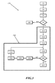
- FIG 2 a first embodiment of the method 70 to diagnose a faulty terminal is illustrated. This method 70 is implemented and operated in the passive optical network described in figure 1 .
- each testing signal transmitter 35 as well as the fault diagnosis unit 60 is enabled.
- mapping tables associated respectively with the splitters are loaded in the memory of the fault diagnosis unit 60.
- Each mapping table contains the indexing by integer counting numbers of the network terminals connected to one splitter.
- the fault diagnosis unit 60 selects the splitter line and the associated splitter on which a fault has been detected, for instance the splitter line 56 and the splitter 46.
- the fault diagnosis unit 60 send a common request to all the network terminals 20, 22, 24, 26 connected to the splitter 46 to be silent namely not to transmit any signal while remaining powered ON, and attempts to detect an optical signal power from the splitter.
- the fault diagnosis unit 60 decides in a step 78 that the fault diagnosis process can be dealt with a standard process 80.
- the fault diagnosis unit 60 executes the process with the set 90 of steps 92, 94, 95, 96, 98, 100, 102, 104, 106, 108 and 110.
- the standard process 80 consists of scanning or probing for each splitter each network terminal and gradually increasing one by one the number of network terminals transmitting in their allocated slots according to a predetermined TDMA access scheme until the faulty network terminal is observed.
- the average power measuring means of the fault diagnosis unit 60 measures over a scaled level range the power of the received signal at optical line termination level and stores in the memory the value of this measured power referred as to the reference average power.
- the value 1 for k corresponds to the network terminal 20 according to one of the mapping tables defined in step 72.
- step 95 a request is sent to the network terminal 20 for transmitting a testing signal.
- the network terminal 20 using its testing signal transmitter attempts to transmit the testing signal. It is assumed here that the transmission of the testing signal is correctly carried out.
- the average power measuring unit of the fault diagnosis unit 60 power measures the average power of the signal received at the optical line termination.
- the disturbing signal is generated by another network terminal not yet determined among the network terminals 22, 24, 26.
- the received signal issued from the splitter 46 which acts as an adder for the network terminal in upstream (from network terminal to OLT), is the superposition of the signal transmitted from the network terminal and the disturbing signal.
- the measured average receive power is compared to the reference average power determined in the step 92.
- the process continues to the step 104, otherwise the network terminal mapped to the current counting value k is considered as the faulty terminal.
- step 104 the process runs to step 104.
- the current probed network terminal 20 is requested to be silent and in a step 106, the current scanning counter value k equal to 1 is increased by one and the current value becomes equal to 2, which corresponds to address as the current probed network terminal the network terminal as referred to 22 according the mapping table defined in the step 72.
- a request is sent to the terminal 22 to transmit a testing signal.
- a step 110 the network terminal 22 attempts to transmit the testing signal.
- the network terminal 22 is the faulty terminal.
- the received signal received at the optical line termination level consists of the disturbing signal alone, the average power thereof has been measured in the step 92.
- step 100 the average power measurement of step 98 and the reference average power measured in the step 92 are compared.
- the network terminal 22 would not have been the faulty network terminal, the process described by steps 104, 106, 108, 110, 98, 100 would have been repeated until the identification of the faulty terminal in the step 102.
- Figure 3 a second embodiment of the method to diagnose a faulty terminal is illustrated. This method is also implemented and operated in the passive optical network describe in figure 1 .
- the method 170 comprises at the beginning of the process the same steps 72, 74, 76, 78, 80 as the method 70.
- the method 170 differs from the method 70 by replacing the process 90 by a process 190 specific to the second embodiment.
- the process 190 is a set of steps 192, 194, 196, 198, 200, 202, 204, 206, 208 and 210.
- the value 1 for k corresponds to the network terminal 20 according one of the mapping tables as defined in step 72.
- step 194 a request is sent to the network terminal 20 for transmitting a testing signal.
- the network terminal 20 using its testing signal transmitter 35 attempts to transmit the testing signal.
- the used testing signal comprises a pseudorandom sequence that exhibits good properties of autocorrelation as well known CDMA type sequences.
- one or several correlating units calculate one or several cross correlations between a part or the totality of the signal received at the optical line termination and a mimic of the expected pseudorandom sequence.
- a step 200 the result of the detection of the testing signal is examined.
- the processing continues to the step 204, otherwise the network terminal mapped to the current counting value k is considered as the faulty terminal.
- step 204 is carried out.
- the current probed network terminal 20 is requested to be silent and in a step 206, the scanning counter value k equal to 1 is increased by one and the current value k becomes equal to 2, which corresponding to address the current probed network terminal as referred to 22 according the mapping table defined in the step 72.
- a request is sent to the terminal 22 to transmit a testing signal.
- the network terminal 22 attempts to transmit the testing signal which is, here, the same testing signal as one used by network terminal 20.
- steps 198, 200 and 204 are carried out in the same way as for the network terminal 20 with same outputs, namely the testing signal generated from network terminal 22 is successfully detected and the process continues to step 206.
- the scanning counter value k equal to 2 is increased by one and the current value becomes equal to 3, which corresponding to address therefore the current probed network terminal as referred to 24 according the mapping table defined in the step 72.
- a request is sent to the network terminal 24 to transmit a testing signal.
- the network terminal 24 attempts to transmit the same testing signal as network terminal 20 and 22 performed.
- the network terminal 24 is the faulty terminal.
- the result of detection is declared unsuccessful in the step 202 that runs to the step 202 wherein the network terminal 24 is determined as the faulty terminal.
- using a pseudorandom sequence encoded into the testing signal provides a higher probability to detect the faulty terminal compared to the first embodiment since the detection sensitivity is increased in case detection is directed towards a network terminal correctly operating.
- testing signal transmitter 35 It also covers more common hardware and software functionalities shared both by the testing signal transmitter 35 and the usual traffic data transmitter of the network terminal.
- the steps 78, 80, 204 are removed.
- the diagnosis method is executed while the data traffic service continues, even if the availability of the network may be lower because of the presence of a faulty terminal, since the traffic data that are not affected by the faulty network terminal can continue to flow and the diagnosis will slightly interfere with the normal traffic service.
- the pseudorandom sequences used by the network terminals are different.
- the fault diagnosis tasks can be carried out in parallel and the global fault diagnosis process is accelerated.
- a splitter is replaced by a set of cascaded splitters.
- a set of cascaded splitters comprises one splitter downwardly connected to four splitters, each splitter having four input lines.
Landscapes
- Physics & Mathematics (AREA)
- Electromagnetism (AREA)
- Engineering & Computer Science (AREA)
- Computer Networks & Wireless Communication (AREA)
- Signal Processing (AREA)
- Optical Communication System (AREA)
- Small-Scale Networks (AREA)
Abstract
sending from the optical line termination on a one probed terminal basis a request to one network terminal for transmitting a testing signal,
attempting from the requested network terminal to transmit the testing signal,
analysing the signal received at the optical line termination issued from the splitter in order to detect the testing signal and provide a detection result ,
determining whether the probed network terminal is a faulty terminal on the basis of the detection result.
Description
- The present invention relates to a method for pinpointing a faulty network terminal in a Passive Optical Network (PON) and a Passive Optical Network (PON) wherein the method is implemented.
- Passive Optical Networks are well known as being one among the two architectures of the access part of optical networks.
- According to the Passive Optical Network (PON) architecture, also called Point to Multipoint architecture, a conventional Passive Optical Network (PON) comprises an Optical Line Termination (OLT) upwardly connected to a switch belonging to a high rate optical networking infrastructure and a set of optical splitters wherein each optical splitter is upwardly connected to the Optical Line Termination (OLT) through a different respective dedicated fibre.
- The Passive Optical Network also comprises several network terminals, located inside the customer premises also called Optical Network Terminals (ONTs) grouped within clusters.
- The network terminals of each cluster share the same optical fibre from the Optical Line termination to the splitter respectively associated to the corresponding cluster.
- The network terminals of each cluster are connected to the corresponding optical splitter through different respective dedicated fibres.
- In the Passive Optical Network architecture, since only one fibre is shared by the network terminals of one cluster both for uplink (from the network terminals of the cluster to OLT) and downlink (from OLT to network terminals of the cluster), uplink and downlink data are transmitted simultaneously using two distinct wavelengths of the laser. Such a downlink/uplink access scheme is referred as wavelength duplex access.
- In the uplink direction, a time slot is allocated repeatedly to each user of a cluster, wherein transmission of data is enabled.
- Time slots are configured into a frame in such a way to avoid simultaneous transmission which could collide. Such an uplink access scheme from the network terminals to the OLT is conventionally called a Time Division Multiplexing Access (TDMA).
- When intentionally or unintentionally the network terminal is not transmitting its data in the allocated time slot but is transmitting data in other times slots allocated to some other network terminals, there is collision between the data of the faulty network terminal and the data sent by the other network terminals.
- Insofar, a well known way to diagnose the fault and in particular to identify and locate, namely to pinpoint the faulty network terminal is to send a maintenance personal in the place where the splitters are grouped. By disconnecting manually, one by one, each network terminal line connection from the associated splitter and performing loopback tests with the aid of the remaining network terminals connected to the splitter, the technician is able to find and identify the faulty network terminal.
- A major drawback of this method is the time and the cost required to send a technician in the splitter premises, to disconnect and reconnect the connexions of the network terminals to the splitter. This diagnosis method is particularly difficult to use when the network terminal fibre is spliced to the splitter fibre.
- The aim of the invention is to provide a diagnosis method to identify and locate a faulty user in a Passive Optical Network which is simpler to carry out for maintenance and which provide time saving in the maintenance tasks.
- The invention accordingly relates to Method for pinpointing a faulty network terminal in a passive optical network (PON) comprising an optical line termination, a splitter upwardly connected to the optical line termination through a single fibre and at least two network terminals, each network terminal upwardly connected to the splitter through a different dedicated fibre, the splitter acting as a adder for superposing any signals transmitted from the network terminals,
characterized in that the method comprises the following steps consisting of subsequently for each terminal: - 1a.) requesting to one identified network terminal for transmitting a testing signal, and
- 1b.) attempting from the requested network terminal to transmit the testing signal, and
- 1c.) analysing the signal received at the optical line termination issued from the splitter in order to detect the testing signal and provide a detection result,
- According to particular embodiments, the method for pinpointing a network terminal comprises one or more of the following characteristics:
- the requesting step is carried out by sending request from the optical line termination,
- the determining step is carried after analysing step for each terminal, before analysing the signal received from another requested network terminal,
- the testing signal is a signal comprised in the set of the carrier wave signal and the data modulated signal,
- it comprises a first initial step of detecting the presence of a reference signal at the optical line termination when all the network terminals are requested to be silent,
- it comprises a step of measuring the average power of the received signal over a scaled level range in order to obtain a reference average received power after a successful detection of the presence of the reference signal in the step,
- in the step of analysing the signal received at the optical line termination, the analysis is carried out by measuring the average of the received power when the requested network terminal transmits the testing signal while the remaining network terminal are requested to be silent,
- the testing signal is an encoded signal encoded by a pseudorandom data sequence of CDMA type operating as a signature,
- the pseudorandom data sequence encoding the testing sequence is the same for all network terminals,
- analysing is achieved by correlating the received signal at the optical line termination with the pseudorandom data sequence of the testing signal,
- when the probed network terminal is attempting to transmit the testing signal the remaining network terminal have been requested to be silent, and
- when the probed network terminal is attempting to transmit the testing signal the remaining network terminal continue to operate in a normal traffic mode.
- The invention also relates to a passive optical network (PON) comprising an optical line termination, a splitter upwardly connected the optical line termination through a single fibre and at least two network terminals, each network terminal upwardly connected to the splitter through different dedicated fibre, the splitter acting as a adder for superposing any signals transmitted from the network terminals,
characterized in that
each network terminal comprises a testing signal transmitter (35) able to generate and transmit to the respective splitter a testing signal upon receipt the request issued from the optical line termination,
the optical line termination comprises a fault diagnosis unit for sending on a one probed terminal basis a request to a network terminal for transmitting a testing signal, for analyzing the signal received at the optical line termination issued from the splitter in order to detect the testing signal and provide a detection result, and for determining whether the probed network terminal is a faulty terminal on the basis of the detection result. - According to particular embodiments, the passive optical network system comprises one or more of the following characteristics:
- the testing signal is a signal comprised in the set of the carrier wave signal and the data modulated signal,
- the fault diagnosis unit comprises an average power detector and a comparator for comparing two different measured average power values,
- each testing signal transmitter comprises a pseudorandom data sequence encoder for encoding the testing signal,
- the analysis diagnosis unit comprises a correlating unit suited for detecting the pseudorandom data sequence.
- The invention also relates to a fault diagnosis unit for pinpointing a faulty network terminal in a passive optical network (PON) characterized in that it comprises:
- means for sending a request to the probed network terminal for transmitting a testing signal, and
- means for analyzing the signal received at an optical line termination issued from a splitter in order to detect the testing signal and provide a detection result, and
- means for determining whether the probed network terminal is a faulty terminal on the basis of the detection result,
- means for managing the tasks of requesting, analyzing and determining.
- According to particular embodiments, the diagnosis unit comprises one or more of the following characteristics:
- it comprises an average power detector and a comparator for comparing two different measured average power values,
- it comprises at least one correlating unit suited for detecting the pseudorandom data sequence.
- A better understanding of the invention will be facilitated by reading the following description, which is given solely by way of examples and with reference to drawings, in which:
-
Figure 1 is a passive optical network architecture wherein the method according the invention is implemented, -
Figure 2 is a first embodiment flow chart of the method used in the passive optical network of theFigure 1 , and -
Figure 3 isFigure 2 is a second embodiment flow chart of the method used in the passive optical network of theFigure 1 . - According to
figure 1 , anoptical network 2 generally comprises a high rate datanetworking infrastructure part 4, anetwork terminal part 6 and an optical access part 8 linking thenetworking infrastructure 4 to thenetwork terminal part 6. - The high rate data
networking infrastructure part 4 comprises a set ofhigh rate switches - The
switches figure 1 , only one optical access part 8 is illustrated and only oneswitch 12 is shown connected to the optical access part 8 through a single fibre orcopper line 16. - The
network terminal part 6 comprises a set ofnetwork terminals switch 12 through the optical access part 8. - The terminals are grouped within a number of
clusters - In the
figure 1 , the twonetwork terminals 18 are grouped within thecluster 30, the fournetwork terminals cluster 32 and the four network terminals 28 are grouped within thecluster 34. - Each
network terminal testing signal transmitter 35 able to generate a testing signal. - The
testing signal transmitter 35 and the user normal data transmitter share common hardware or software functionalities in a common part, so that a testing of at least a part of the user normal data transmitter is effective. - The
testing signal transmitter 35 comprises a testing signal generator and a transmitter front end not shown that are partially or totally common to the user normal data transmitter. - Here, the testing signal transmitter front end is the same part as one forming the user data transmitter front end.
- Testing signals generated by the
testing signal transmitter 35 are of several types. - A first type of signal is a carrier wave signal made of a pure sinusoid.
- A second type of signal is a common traffic data modulated signal.
- A third type of signal is a signal of first type or second type encoded by a pseudorandom data sequence as used in CDMA (Code Division Multiplexing Access).
- A fourth type of signal is a signal obtained by combining any of the first, second, third type signals.
- The optical access part 8 comprises as an interface relative to the
networking infrastructure part 4 an optical line termination 36 connected to theswitch 12 through the fibre orcopper line 16. - The optical line termination 36 and the
switch 12 are forming acentral office 38 also called Point of Presence. - The optical access part 8 also comprises a
set 40 ofsplitters set 50 offeeder lines - The two
splitters 42 are not used and not connected to any lines. - The three
splitters different feeder lines - The two feeder lines 52 are not used and not connected to any device.
- The optical line termination 36 comprises a
fault diagnosis unit 60 with a processor unit including counters and a memory. - The
fault diagnosis unit 60 is able to manage the process of diagnosis by sending according a predetermined time sequence requests to a cluster of network terminals so that each network terminal of the cluster transmits at its turn a testing signal and receiving the testing signals transmitted from the network terminals through the associated splitter. - The
fault diagnosis unit 60 also comprises an average power measuring unit not shown and one or several correlating units not shown suited for calculating one or several cross-correlations between a part or the totality of a signal received at the optical line termination 36 and a mimic of the expected pseudorandom sequence encoded within the testing signal. - In
Figure 2 , a first embodiment of themethod 70 to diagnose a faulty terminal is illustrated. Thismethod 70 is implemented and operated in the passive optical network described infigure 1 . - In a
first step 72, eachtesting signal transmitter 35 as well as thefault diagnosis unit 60 is enabled. During thestep 72, mapping tables associated respectively with the splitters are loaded in the memory of thefault diagnosis unit 60. Each mapping table contains the indexing by integer counting numbers of the network terminals connected to one splitter. - Then, in a
step 74 thefault diagnosis unit 60 selects the splitter line and the associated splitter on which a fault has been detected, for instance the splitter line 56 and thesplitter 46. - Subsequently in a
step 76, thefault diagnosis unit 60 send a common request to all thenetwork terminals splitter 46 to be silent namely not to transmit any signal while remaining powered ON, and attempts to detect an optical signal power from the splitter. - If no optical signal power is sensed at optical line termination by the power measuring unit detector, the
fault diagnosis unit 60 decides in astep 78 that the fault diagnosis process can be dealt with astandard process 80. - If power is detected, the
fault diagnosis unit 60 executes the process with theset 90 ofsteps - The
standard process 80 consists of scanning or probing for each splitter each network terminal and gradually increasing one by one the number of network terminals transmitting in their allocated slots according to a predetermined TDMA access scheme until the faulty network terminal is observed. - In the
first step 92 of theset 90, while all thenetwork terminals fault diagnosis unit 60 measures over a scaled level range the power of the received signal at optical line termination level and stores in the memory the value of this measured power referred as to the reference average power. - Then in a
step 94, a scanning counter of the probed network terminals which outputs a current integer value k, is initialized by inputting 1 in k value (k=1). - The value 1 for k corresponds to the
network terminal 20 according to one of the mapping tables defined instep 72. - In the following
step 95, a request is sent to thenetwork terminal 20 for transmitting a testing signal. - In the
step 96, thenetwork terminal 20 using its testing signal transmitter attempts to transmit the testing signal. It is assumed here that the transmission of the testing signal is correctly carried out. - Then, in a
step 98, the average power measuring unit of thefault diagnosis unit 60 power measures the average power of the signal received at the optical line termination. - Since the
network terminal 20 is correctly working, the disturbing signal is generated by another network terminal not yet determined among thenetwork terminals - The received signal issued from the
splitter 46, which acts as an adder for the network terminal in upstream (from network terminal to OLT), is the superposition of the signal transmitted from the network terminal and the disturbing signal. - The probability that the actual average power of this interference type signal is the same as the average power of the disturbing alone is very low and it can even be expected that the actual average received power will differ from the average power of the disturbing signal referred as to the reference average signal power in the
step 92. - Subsequently, in a
step 100, the measured average receive power is compared to the reference average power determined in thestep 92. - If any change of average power is observed, the process continues to the
step 104, otherwise the network terminal mapped to the current counting value k is considered as the faulty terminal. - Here, as
network terminal 20 is assumed as working correctly, the process runs to step 104. - In the
step 104, the current probednetwork terminal 20 is requested to be silent and in astep 106, the current scanning counter value k equal to 1 is increased by one and the current value becomes equal to 2, which corresponds to address as the current probed network terminal the network terminal as referred to 22 according the mapping table defined in thestep 72. - Then in a
step 108, a request is sent to the terminal 22 to transmit a testing signal. - In a
step 110, thenetwork terminal 22 attempts to transmit the testing signal. - Here, we will assume that the
network terminal 22 is the faulty terminal. - In this case, the received signal received at the optical line termination level consists of the disturbing signal alone, the average power thereof has been measured in the
step 92. - It is therefore expected that that measured signal power in the
step 98 for the current probednetwork terminal 22 will be the same as the reference average power measured in thestep 92. - In a following
step 100, the average power measurement ofstep 98 and the reference average power measured in thestep 92 are compared. - If the comparison does not exhibit any change, which is the case of this example, then it is decided in a
step 102 that the network terminal corresponding to the value of k equal to 2, namely thenetwork terminal 22 is the faulty network terminal. - In the case, the
network terminal 22 would not have been the faulty network terminal, the process described bysteps step 102. - In
Figure 3 , a second embodiment of the method to diagnose a faulty terminal is illustrated. This method is also implemented and operated in the passive optical network describe infigure 1 . - The
method 170 comprises at the beginning of the process thesame steps method 70. - The
method 170 differs from themethod 70 by replacing theprocess 90 by aprocess 190 specific to the second embodiment. - The
process 190 is a set ofsteps - In the
first step 192 of theprocess 190, a scanning counter of the probed network terminals which outputs a current integer value k, is initialized by inputting 1 in k value (k=1). - The value 1 for k corresponds to the
network terminal 20 according one of the mapping tables as defined instep 72. - In the
following step 194, a request is sent to thenetwork terminal 20 for transmitting a testing signal. - In the
subsequent step 196, thenetwork terminal 20 using itstesting signal transmitter 35 attempts to transmit the testing signal. - The used testing signal comprises a pseudorandom sequence that exhibits good properties of autocorrelation as well known CDMA type sequences.
- It is assumed here that the transmission of the testing signal is correctly carried out..
- Then, in the
step 198, one or several correlating units calculate one or several cross correlations between a part or the totality of the signal received at the optical line termination and a mimic of the expected pseudorandom sequence. - Since the
network terminal 20 is correctly working, a successful matching and retrieval of the pseudorandom sequence encoded into the testing signal generated fromnetwork terminal 20 is achieved. - This successful detection is obtained even in the presence of the disturbing signal which acts as an interferer for the testing signal correctly transmitted.
- The well known spread spectrum properties of a pseudorandom sequence with good autocorrelation and cross-correlation properties are advantageously exploited to lower the susceptibility of the testing signal to the disturbing signal acting as a jammer.
- Thus, the probability to detect the testing signal in the presence of the disturbing signal is high.
- Subsequently, in a
step 200, the result of the detection of the testing signal is examined. - If the detection of the testing signal is successful, the processing continues to the
step 204, otherwise the network terminal mapped to the current counting value k is considered as the faulty terminal. - Here, as
network terminal 20 is assumed as working correctly, thestep 204 is carried out. - In the
step 204, the current probednetwork terminal 20 is requested to be silent and in astep 206, the scanning counter value k equal to 1 is increased by one and the current value k becomes equal to 2, which corresponding to address the current probed network terminal as referred to 22 according the mapping table defined in thestep 72. - Then in a
step 208, a request is sent to the terminal 22 to transmit a testing signal. - In the
step 210, thenetwork terminal 22 attempts to transmit the testing signal which is, here, the same testing signal as one used bynetwork terminal 20. - It is assumed here that the transmission of the testing signal is correctly carried out by the
network terminal 22. - Then, the
steps network terminal 20 with same outputs, namely the testing signal generated fromnetwork terminal 22 is successfully detected and the process continues to step 206. - In the
step 206, the scanning counter value k equal to 2 is increased by one and the current value becomes equal to 3, which corresponding to address therefore the current probed network terminal as referred to 24 according the mapping table defined in thestep 72. - Then in the
step 208, a request is sent to thenetwork terminal 24 to transmit a testing signal. - In the
step 210, thenetwork terminal 24 attempts to transmit the same testing signal asnetwork terminal - Here, we will assume that the
network terminal 24 is the faulty terminal. - Since the
network terminal 24 is not correctly working, matching and retrieval of the pseudorandom sequence encoded into the testing signal generated fromnetwork terminal 24 cannot be achieved. - Therefore the result of detection is declared unsuccessful in the
step 202 that runs to thestep 202 wherein thenetwork terminal 24 is determined as the faulty terminal. - In case the
network terminal 24 would not have been the faulty network terminal, the process described bysteps step 102, here thenetwork terminal 26. - Advantageously, using a pseudorandom sequence encoded into the testing signal provides a higher probability to detect the faulty terminal compared to the first embodiment since the detection sensitivity is increased in case detection is directed towards a network terminal correctly operating.
- It also covers more common hardware and software functionalities shared both by the
testing signal transmitter 35 and the usual traffic data transmitter of the network terminal. - In a variant of the second embodiment, the
steps - In a variant of the second embodiment, the pseudorandom sequences used by the network terminals are different. In such a case, the fault diagnosis tasks can be carried out in parallel and the global fault diagnosis process is accelerated.
- In a variant if the first embodiment or the second embodiment, a splitter is replaced by a set of cascaded splitters.
- For example, a set of cascaded splitters comprises one splitter downwardly connected to four splitters, each splitter having four input lines.
in the step of determining, the probed network terminal is judged as a faulty terminal when the expected testing signal has not been detected,
Claims (19)
- Method for pinpointing a faulty network terminal in a passive optical network (PON) comprising an optical line termination (36), a splitter (46) upwardly connected to the optical line termination (36) through a single fibre (56) and at least two network terminals (20, 22), each network terminal (20, 22) upwardly connected to the splitter (46) through a different dedicated fibre, the splitter (46) acting as a adder for superposing any signals transmitted from the network terminals (20, 22),
characterized in that the method comprises the following steps consisting of subsequently for each terminal:1a.) requesting (95, 194) to one identified network terminal (20, 22) for transmitting a testing signal, and1b.) attempting (96, 196) from the requested network terminal (20, 22) to transmit the testing signal, and1c.) analysing (98, 100, 198, 200) the signal received at the optical line termination (36) issued from the splitter (46) in order to detect the testing signal and provide a detection result ,and determining (102, 202) whether the probed identified network terminal is a faulty terminal on the basis of the detection results. - Method according to the claim 1, characterized in that requesting step (95, 194) is carried out by sending request from the optical line termination.
- Method according to any of the claims 1 to 2, characterized in that the determining step (102, 202) is carried after analysing step (98, 100, 198, 200) for each terminal, before analysing the signal received from another requested network terminal.
- Method according to any of the claims 1 to 3, characterized in that the testing signal is a signal comprised in the set of the carrier wave signal and the data modulated signal.
- Method according to any of the claims 1 to 4, characterized in that it comprises a first initial step (76) of detecting the presence of a reference signal at the optical line termination when all the network terminals are requested to be silent.
- Method according to the claim 5, characterized in that it comprises a step (92) of measuring the average power of the received signal over a scaled level range in order to obtain a reference average received power after a successful detection of the presence of the reference signal in the step (76).
- Method according to the claim 6, characterized in that
in the step of analysing (98, 100) the signal received at the optical line termination (36), the analysis is carried out by measuring (98) the average of the received power when the requested network terminal (20, 22) transmits the testing signal while the remaining network terminal are requested to be silent,
the measured received power is compared (100) to the reference average received power, and in case change of the received power is observed the testing signal is considered as being detected,
in the step of determining, the probed network terminal is judged as a faulty terminal when the expected testing signal has not been detected. - Method according to any of the claims 1 to 4, characterized in that the testing signal is an encoded signal encoded by a pseudorandom data sequence of CDMA type operating as a signature.
- Method according to claim 8, characterized in that the pseudorandom data sequence encoding the testing sequence is the same for all network terminals.
- Method according to any of the claims 8 to 9, characterized in that
analysing (198, 200) is achieved by correlating the received signal at the optical line termination (36) with the pseudorandom data sequence of the testing signal. - Method according to any of the claims 8 to 10, characterized in that when the probed network terminal (20, 22) is attempting to transmit the testing signal the remaining network terminal have been requested to be silent.
- Method according to any of the claims 8 to 10, characterized in that when the probed network terminal (20, 22) is attempting to transmit the testing signal the remaining network terminal continue to operate in a normal traffic mode.
- Passive optical network (PON) comprising an optical line termination (36) , a splitter (46) upwardly connected the optical line termination (36) through a single fibre and at least two network terminals (20, 22), each network terminal (20, 22) upwardly connected to the splitter (46) through different dedicated fibre, the splitter (46) acting as a adder for superposing any signals transmitted from the network terminals (20, 22),
characterized in that each network terminal (20, 22) comprises a testing signal transmitter (35) able to generate and transmit to the respective splitter (46) a testing signal upon receipt the request issued from the optical line termination (36),
the optical line termination (36) comprises a fault diagnosis unit (60) for sending on a one probed terminal basis a request to a network terminal for transmitting a testing signal, for analyzing the signal received at the optical line termination issued from the splitter in order to detect the testing signal and provide a detection result, and for determining whether the probed network terminal is a faulty terminal on the basis of the detection result. - Passive optical network (PON) according to claim 13, characterized in that the testing signal is a signal comprised in the set of the carrier wave signal and the data modulated signal.
- Passive optical network (PON) according to claim any of claims 13 and 14, characterized in that
the fault diagnosis unit (60) comprises an average power detector and a comparator for comparing two different measured average power values. - Passive optical network (PON) according to claim any of claims 13 and 15, characterized in that
each testing signal transmitter (35) comprises a pseudorandom data sequence encoder for encoding the testing signal,
the analysis diagnosis unit (60) comprises a correlating unit suited for detecting the pseudorandom data sequence. - Fault diagnosis unit for pinpointing a faulty network terminal in a passive optical network (PON) characterized in that it comprises:means for sending a request to the probed network terminal for transmitting a testing signal, andmeans for analyzing the signal received at an optical line termination issued from a splitter in order to detect the testing signal and provide a detection result, andmeans for determining whether the probed network terminal is a faulty terminal on the basis of the detection result,means for managing the tasks of requesting, analyzing and determining.
- Fault diagnosis unit according to claim 17, characterized in that
it comprises an average power detector and a comparator for comparing two different measured average power values. - Fault diagnosis unit according to claim 17, characterized in that it comprises at least one correlating unit suited for detecting the pseudorandom data sequence.
Priority Applications (3)
| Application Number | Priority Date | Filing Date | Title |
|---|---|---|---|
| AT08300060T ATE537620T1 (en) | 2008-01-30 | 2008-01-30 | METHOD FOR LOCATING A FAULTY NETWORK TERMINAL IN A PASSIVE OPTICAL NETWORK (PON) |
| EP08300060A EP2086129B1 (en) | 2008-01-30 | 2008-01-30 | Method for pinpointing a faulty network terminal in a Passive Optical Network (PON) |
| JP2009018727A JP5232032B2 (en) | 2008-01-30 | 2009-01-29 | Method for identifying a failed network terminal in a passive optical network (PON) |
Applications Claiming Priority (1)
| Application Number | Priority Date | Filing Date | Title |
|---|---|---|---|
| EP08300060A EP2086129B1 (en) | 2008-01-30 | 2008-01-30 | Method for pinpointing a faulty network terminal in a Passive Optical Network (PON) |
Publications (2)
| Publication Number | Publication Date |
|---|---|
| EP2086129A1 true EP2086129A1 (en) | 2009-08-05 |
| EP2086129B1 EP2086129B1 (en) | 2011-12-14 |
Family
ID=39497056
Family Applications (1)
| Application Number | Title | Priority Date | Filing Date |
|---|---|---|---|
| EP08300060A Not-in-force EP2086129B1 (en) | 2008-01-30 | 2008-01-30 | Method for pinpointing a faulty network terminal in a Passive Optical Network (PON) |
Country Status (3)
| Country | Link |
|---|---|
| EP (1) | EP2086129B1 (en) |
| JP (1) | JP5232032B2 (en) |
| AT (1) | ATE537620T1 (en) |
Cited By (1)
| Publication number | Priority date | Publication date | Assignee | Title |
|---|---|---|---|---|
| EP2403269A2 (en) | 2010-06-30 | 2012-01-04 | ECI Telecom Ltd. | Technology for fault allocation in passive optical networks (PON) |
Citations (5)
| Publication number | Priority date | Publication date | Assignee | Title |
|---|---|---|---|---|
| GB2330280A (en) * | 1997-10-08 | 1999-04-14 | Fujitsu Ltd | Fault supervision of an optical network |
| US20040017965A1 (en) * | 2002-07-29 | 2004-01-29 | Hideji Abe | Subscriber line terminal device and loopback test method |
| US20040096216A1 (en) * | 2002-11-19 | 2004-05-20 | Fujitsu Limited | Transmission route applicability inspection system in wavelength division multiplexing optical transmission network system |
| US20040156635A1 (en) * | 2003-02-06 | 2004-08-12 | Nortel Networks Limited | Method and apparatus for the transmission fault detection in an access network |
| US20060013582A1 (en) * | 2002-10-07 | 2006-01-19 | Jurgen Fischer | Optical communications processing system, components and operating method thereof |
Family Cites Families (2)
| Publication number | Priority date | Publication date | Assignee | Title |
|---|---|---|---|---|
| JP3867558B2 (en) * | 2001-11-22 | 2007-01-10 | Kddi株式会社 | Communication system and node measurement device |
| TW583677B (en) * | 2002-07-25 | 2004-04-11 | Ememory Technology Inc | Flash memory with sensing amplifier using load transistors driven by coupled gate voltages |
-
2008
- 2008-01-30 AT AT08300060T patent/ATE537620T1/en active
- 2008-01-30 EP EP08300060A patent/EP2086129B1/en not_active Not-in-force
-
2009
- 2009-01-29 JP JP2009018727A patent/JP5232032B2/en not_active Expired - Fee Related
Patent Citations (5)
| Publication number | Priority date | Publication date | Assignee | Title |
|---|---|---|---|---|
| GB2330280A (en) * | 1997-10-08 | 1999-04-14 | Fujitsu Ltd | Fault supervision of an optical network |
| US20040017965A1 (en) * | 2002-07-29 | 2004-01-29 | Hideji Abe | Subscriber line terminal device and loopback test method |
| US20060013582A1 (en) * | 2002-10-07 | 2006-01-19 | Jurgen Fischer | Optical communications processing system, components and operating method thereof |
| US20040096216A1 (en) * | 2002-11-19 | 2004-05-20 | Fujitsu Limited | Transmission route applicability inspection system in wavelength division multiplexing optical transmission network system |
| US20040156635A1 (en) * | 2003-02-06 | 2004-08-12 | Nortel Networks Limited | Method and apparatus for the transmission fault detection in an access network |
Cited By (3)
| Publication number | Priority date | Publication date | Assignee | Title |
|---|---|---|---|---|
| EP2403269A2 (en) | 2010-06-30 | 2012-01-04 | ECI Telecom Ltd. | Technology for fault allocation in passive optical networks (PON) |
| US8805184B2 (en) | 2010-06-30 | 2014-08-12 | Eci Telecom Ltd. | Technology for fault allocation in passive optical networks (PON) |
| EP3386210A1 (en) | 2010-06-30 | 2018-10-10 | ECI Telecom Ltd | Technology for fault allocation in passive optical networks (pon) |
Also Published As
| Publication number | Publication date |
|---|---|
| JP2009182965A (en) | 2009-08-13 |
| JP5232032B2 (en) | 2013-07-10 |
| EP2086129B1 (en) | 2011-12-14 |
| ATE537620T1 (en) | 2011-12-15 |
Similar Documents
| Publication | Publication Date | Title |
|---|---|---|
| EP3282242B1 (en) | Optical time-domain reflectometer | |
| CN111010228B (en) | Port identification method, device and system and optical splitter | |
| JP3446211B2 (en) | Detection of self-stimulation signal in optical transmission system | |
| US8805184B2 (en) | Technology for fault allocation in passive optical networks (PON) | |
| US20060051088A1 (en) | Apparatus for remotely determining fault of subscriber terminals and method thereof | |
| EP2847896B1 (en) | Monitoring of a pon | |
| JPH03113930A (en) | Optical fiber linkage test device of data communication network | |
| EP2337240A1 (en) | Multichannel WDM-PON module with integrated OTDR function | |
| CN105530046A (en) | Method and system for realizing automatic tests on light power and branch attenuation faults | |
| CN110266374A (en) | It is a kind of can high precision monitor TDM-PON second level branch trouble device and method | |
| WO2013107232A1 (en) | Detection method and system based on pon system | |
| CN110178320B (en) | High resolution line monitoring method and optical communication system using the same | |
| WO2014002741A1 (en) | Optical path monitoring method and optical path monitoring system | |
| KR20130093829A (en) | Apparatus and method for monitoring optical line | |
| EP2903182A1 (en) | Diagnosing faults in optical networks | |
| EP2086129B1 (en) | Method for pinpointing a faulty network terminal in a Passive Optical Network (PON) | |
| JP2012029176A (en) | Hinderance onu specification device, hinderance onu specification method and pon system | |
| CN101567724B (en) | Network situation detection system and method | |
| CN110518966B (en) | ONU positioning system and positioning method based on orthogonal coding | |
| US7522835B1 (en) | Method of testing bit error rates for a wavelength division multiplexed optical communication system | |
| US6859828B1 (en) | Bi-directional test system for network analysis | |
| CN115967445B (en) | Method, equipment and system for generating optical network topology | |
| KR101889553B1 (en) | System and method for monitoring optical line | |
| KR101471066B1 (en) | Optical signal strength Measuring device using Reflection. | |
| CN112953628A (en) | OXC optical fiber ID recognition device and method based on OFDR |
Legal Events
| Date | Code | Title | Description |
|---|---|---|---|
| PUAI | Public reference made under article 153(3) epc to a published international application that has entered the european phase |
Free format text: ORIGINAL CODE: 0009012 |
|
| AK | Designated contracting states |
Kind code of ref document: A1 Designated state(s): AT BE BG CH CY CZ DE DK EE ES FI FR GB GR HR HU IE IS IT LI LT LU LV MC MT NL NO PL PT RO SE SI SK TR |
|
| AX | Request for extension of the european patent |
Extension state: AL BA MK RS |
|
| 17P | Request for examination filed |
Effective date: 20091022 |
|
| RAP1 | Party data changed (applicant data changed or rights of an application transferred) |
Owner name: MITSUBISHI ELECTRIC R&D CENTRE EUROPE B.V. Owner name: MITSUBISHI ELECTRIC CORPORATION |
|
| AKX | Designation fees paid |
Designated state(s): AT BE BG CH CY CZ DE DK EE ES FI FR GB GR HR HU IE IS IT LI LT LU LV MC MT NL NO PL PT RO SE SI SK TR |
|
| GRAP | Despatch of communication of intention to grant a patent |
Free format text: ORIGINAL CODE: EPIDOSNIGR1 |
|
| RIN1 | Information on inventor provided before grant (corrected) |
Inventor name: COUDREUSE, JEAN-PIERRE Inventor name: MOREL, PIERRE Inventor name: PAUTONNIER-PERROT, SOPHIE Inventor name: LAVILLONNIERE, ERIC |
|
| GRAS | Grant fee paid |
Free format text: ORIGINAL CODE: EPIDOSNIGR3 |
|
| GRAA | (expected) grant |
Free format text: ORIGINAL CODE: 0009210 |
|
| AK | Designated contracting states |
Kind code of ref document: B1 Designated state(s): AT BE BG CH CY CZ DE DK EE ES FI FR GB GR HR HU IE IS IT LI LT LU LV MC MT NL NO PL PT RO SE SI SK TR |
|
| REG | Reference to a national code |
Ref country code: GB Ref legal event code: FG4D |
|
| REG | Reference to a national code |
Ref country code: CH Ref legal event code: EP |
|
| REG | Reference to a national code |
Ref country code: IE Ref legal event code: FG4D |
|
| REG | Reference to a national code |
Ref country code: DE Ref legal event code: R096 Ref document number: 602008011964 Country of ref document: DE Effective date: 20120315 |
|
| REG | Reference to a national code |
Ref country code: NL Ref legal event code: VDEP Effective date: 20111214 |
|
| PG25 | Lapsed in a contracting state [announced via postgrant information from national office to epo] |
Ref country code: LT Free format text: LAPSE BECAUSE OF FAILURE TO SUBMIT A TRANSLATION OF THE DESCRIPTION OR TO PAY THE FEE WITHIN THE PRESCRIBED TIME-LIMIT Effective date: 20111214 Ref country code: NO Free format text: LAPSE BECAUSE OF FAILURE TO SUBMIT A TRANSLATION OF THE DESCRIPTION OR TO PAY THE FEE WITHIN THE PRESCRIBED TIME-LIMIT Effective date: 20120314 |
|
| LTIE | Lt: invalidation of european patent or patent extension |
Effective date: 20111214 |
|
| PG25 | Lapsed in a contracting state [announced via postgrant information from national office to epo] |
Ref country code: GR Free format text: LAPSE BECAUSE OF FAILURE TO SUBMIT A TRANSLATION OF THE DESCRIPTION OR TO PAY THE FEE WITHIN THE PRESCRIBED TIME-LIMIT Effective date: 20120315 Ref country code: SI Free format text: LAPSE BECAUSE OF FAILURE TO SUBMIT A TRANSLATION OF THE DESCRIPTION OR TO PAY THE FEE WITHIN THE PRESCRIBED TIME-LIMIT Effective date: 20111214 Ref country code: HR Free format text: LAPSE BECAUSE OF FAILURE TO SUBMIT A TRANSLATION OF THE DESCRIPTION OR TO PAY THE FEE WITHIN THE PRESCRIBED TIME-LIMIT Effective date: 20111214 Ref country code: NL Free format text: LAPSE BECAUSE OF FAILURE TO SUBMIT A TRANSLATION OF THE DESCRIPTION OR TO PAY THE FEE WITHIN THE PRESCRIBED TIME-LIMIT Effective date: 20111214 Ref country code: LV Free format text: LAPSE BECAUSE OF FAILURE TO SUBMIT A TRANSLATION OF THE DESCRIPTION OR TO PAY THE FEE WITHIN THE PRESCRIBED TIME-LIMIT Effective date: 20111214 Ref country code: SE Free format text: LAPSE BECAUSE OF FAILURE TO SUBMIT A TRANSLATION OF THE DESCRIPTION OR TO PAY THE FEE WITHIN THE PRESCRIBED TIME-LIMIT Effective date: 20111214 |
|
| PG25 | Lapsed in a contracting state [announced via postgrant information from national office to epo] |
Ref country code: CY Free format text: LAPSE BECAUSE OF FAILURE TO SUBMIT A TRANSLATION OF THE DESCRIPTION OR TO PAY THE FEE WITHIN THE PRESCRIBED TIME-LIMIT Effective date: 20111214 Ref country code: BE Free format text: LAPSE BECAUSE OF FAILURE TO SUBMIT A TRANSLATION OF THE DESCRIPTION OR TO PAY THE FEE WITHIN THE PRESCRIBED TIME-LIMIT Effective date: 20111214 |
|
| PG25 | Lapsed in a contracting state [announced via postgrant information from national office to epo] |
Ref country code: BG Free format text: LAPSE BECAUSE OF FAILURE TO SUBMIT A TRANSLATION OF THE DESCRIPTION OR TO PAY THE FEE WITHIN THE PRESCRIBED TIME-LIMIT Effective date: 20120314 Ref country code: EE Free format text: LAPSE BECAUSE OF FAILURE TO SUBMIT A TRANSLATION OF THE DESCRIPTION OR TO PAY THE FEE WITHIN THE PRESCRIBED TIME-LIMIT Effective date: 20111214 Ref country code: IS Free format text: LAPSE BECAUSE OF FAILURE TO SUBMIT A TRANSLATION OF THE DESCRIPTION OR TO PAY THE FEE WITHIN THE PRESCRIBED TIME-LIMIT Effective date: 20120414 Ref country code: SK Free format text: LAPSE BECAUSE OF FAILURE TO SUBMIT A TRANSLATION OF THE DESCRIPTION OR TO PAY THE FEE WITHIN THE PRESCRIBED TIME-LIMIT Effective date: 20111214 Ref country code: CZ Free format text: LAPSE BECAUSE OF FAILURE TO SUBMIT A TRANSLATION OF THE DESCRIPTION OR TO PAY THE FEE WITHIN THE PRESCRIBED TIME-LIMIT Effective date: 20111214 |
|
| PG25 | Lapsed in a contracting state [announced via postgrant information from national office to epo] |
Ref country code: PT Free format text: LAPSE BECAUSE OF FAILURE TO SUBMIT A TRANSLATION OF THE DESCRIPTION OR TO PAY THE FEE WITHIN THE PRESCRIBED TIME-LIMIT Effective date: 20120416 Ref country code: MC Free format text: LAPSE BECAUSE OF NON-PAYMENT OF DUE FEES Effective date: 20120131 Ref country code: RO Free format text: LAPSE BECAUSE OF FAILURE TO SUBMIT A TRANSLATION OF THE DESCRIPTION OR TO PAY THE FEE WITHIN THE PRESCRIBED TIME-LIMIT Effective date: 20111214 Ref country code: PL Free format text: LAPSE BECAUSE OF FAILURE TO SUBMIT A TRANSLATION OF THE DESCRIPTION OR TO PAY THE FEE WITHIN THE PRESCRIBED TIME-LIMIT Effective date: 20111214 |
|
| REG | Reference to a national code |
Ref country code: CH Ref legal event code: PL |
|
| REG | Reference to a national code |
Ref country code: AT Ref legal event code: MK05 Ref document number: 537620 Country of ref document: AT Kind code of ref document: T Effective date: 20111214 |
|
| PLBE | No opposition filed within time limit |
Free format text: ORIGINAL CODE: 0009261 |
|
| STAA | Information on the status of an ep patent application or granted ep patent |
Free format text: STATUS: NO OPPOSITION FILED WITHIN TIME LIMIT |
|
| REG | Reference to a national code |
Ref country code: IE Ref legal event code: MM4A |
|
| PG25 | Lapsed in a contracting state [announced via postgrant information from national office to epo] |
Ref country code: DK Free format text: LAPSE BECAUSE OF FAILURE TO SUBMIT A TRANSLATION OF THE DESCRIPTION OR TO PAY THE FEE WITHIN THE PRESCRIBED TIME-LIMIT Effective date: 20111214 Ref country code: CH Free format text: LAPSE BECAUSE OF NON-PAYMENT OF DUE FEES Effective date: 20120131 Ref country code: LI Free format text: LAPSE BECAUSE OF NON-PAYMENT OF DUE FEES Effective date: 20120131 |
|
| 26N | No opposition filed |
Effective date: 20120917 |
|
| PG25 | Lapsed in a contracting state [announced via postgrant information from national office to epo] |
Ref country code: IT Free format text: LAPSE BECAUSE OF FAILURE TO SUBMIT A TRANSLATION OF THE DESCRIPTION OR TO PAY THE FEE WITHIN THE PRESCRIBED TIME-LIMIT Effective date: 20111214 |
|
| REG | Reference to a national code |
Ref country code: DE Ref legal event code: R097 Ref document number: 602008011964 Country of ref document: DE Effective date: 20120917 |
|
| PG25 | Lapsed in a contracting state [announced via postgrant information from national office to epo] |
Ref country code: IE Free format text: LAPSE BECAUSE OF NON-PAYMENT OF DUE FEES Effective date: 20120130 Ref country code: AT Free format text: LAPSE BECAUSE OF FAILURE TO SUBMIT A TRANSLATION OF THE DESCRIPTION OR TO PAY THE FEE WITHIN THE PRESCRIBED TIME-LIMIT Effective date: 20111214 |
|
| PG25 | Lapsed in a contracting state [announced via postgrant information from national office to epo] |
Ref country code: FI Free format text: LAPSE BECAUSE OF FAILURE TO SUBMIT A TRANSLATION OF THE DESCRIPTION OR TO PAY THE FEE WITHIN THE PRESCRIBED TIME-LIMIT Effective date: 20111214 |
|
| PG25 | Lapsed in a contracting state [announced via postgrant information from national office to epo] |
Ref country code: MT Free format text: LAPSE BECAUSE OF FAILURE TO SUBMIT A TRANSLATION OF THE DESCRIPTION OR TO PAY THE FEE WITHIN THE PRESCRIBED TIME-LIMIT Effective date: 20111214 |
|
| PG25 | Lapsed in a contracting state [announced via postgrant information from national office to epo] |
Ref country code: ES Free format text: LAPSE BECAUSE OF FAILURE TO SUBMIT A TRANSLATION OF THE DESCRIPTION OR TO PAY THE FEE WITHIN THE PRESCRIBED TIME-LIMIT Effective date: 20120325 |
|
| PGFP | Annual fee paid to national office [announced via postgrant information from national office to epo] |
Ref country code: FR Payment date: 20131212 Year of fee payment: 7 |
|
| PG25 | Lapsed in a contracting state [announced via postgrant information from national office to epo] |
Ref country code: TR Free format text: LAPSE BECAUSE OF FAILURE TO SUBMIT A TRANSLATION OF THE DESCRIPTION OR TO PAY THE FEE WITHIN THE PRESCRIBED TIME-LIMIT Effective date: 20111214 |
|
| PGFP | Annual fee paid to national office [announced via postgrant information from national office to epo] |
Ref country code: DE Payment date: 20140107 Year of fee payment: 7 |
|
| PG25 | Lapsed in a contracting state [announced via postgrant information from national office to epo] |
Ref country code: LU Free format text: LAPSE BECAUSE OF NON-PAYMENT OF DUE FEES Effective date: 20120130 |
|
| PGFP | Annual fee paid to national office [announced via postgrant information from national office to epo] |
Ref country code: GB Payment date: 20140116 Year of fee payment: 7 |
|
| PG25 | Lapsed in a contracting state [announced via postgrant information from national office to epo] |
Ref country code: HU Free format text: LAPSE BECAUSE OF FAILURE TO SUBMIT A TRANSLATION OF THE DESCRIPTION OR TO PAY THE FEE WITHIN THE PRESCRIBED TIME-LIMIT Effective date: 20080130 |
|
| REG | Reference to a national code |
Ref country code: DE Ref legal event code: R119 Ref document number: 602008011964 Country of ref document: DE |
|
| GBPC | Gb: european patent ceased through non-payment of renewal fee |
Effective date: 20150130 |
|
| PG25 | Lapsed in a contracting state [announced via postgrant information from national office to epo] |
Ref country code: DE Free format text: LAPSE BECAUSE OF NON-PAYMENT OF DUE FEES Effective date: 20150801 Ref country code: GB Free format text: LAPSE BECAUSE OF NON-PAYMENT OF DUE FEES Effective date: 20150130 |
|
| REG | Reference to a national code |
Ref country code: FR Ref legal event code: ST Effective date: 20150930 |
|
| PG25 | Lapsed in a contracting state [announced via postgrant information from national office to epo] |
Ref country code: FR Free format text: LAPSE BECAUSE OF NON-PAYMENT OF DUE FEES Effective date: 20150202 |