EP2086069B1 - Cladding-pumped optical fiber gain devices - Google Patents
Cladding-pumped optical fiber gain devices Download PDFInfo
- Publication number
- EP2086069B1 EP2086069B1 EP09005772A EP09005772A EP2086069B1 EP 2086069 B1 EP2086069 B1 EP 2086069B1 EP 09005772 A EP09005772 A EP 09005772A EP 09005772 A EP09005772 A EP 09005772A EP 2086069 B1 EP2086069 B1 EP 2086069B1
- Authority
- EP
- European Patent Office
- Prior art keywords
- section
- optical fiber
- gain
- fiber
- pump
- Prior art date
- Legal status (The legal status is an assumption and is not a legal conclusion. Google has not performed a legal analysis and makes no representation as to the accuracy of the status listed.)
- Expired - Lifetime
Links
- 239000013307 optical fiber Substances 0.000 title claims description 38
- 239000000835 fiber Substances 0.000 claims description 60
- 238000005086 pumping Methods 0.000 claims description 7
- 230000004927 fusion Effects 0.000 claims 2
- 230000003287 optical effect Effects 0.000 description 13
- 238000005253 cladding Methods 0.000 description 10
- 229910052691 Erbium Inorganic materials 0.000 description 6
- 229910052761 rare earth metal Inorganic materials 0.000 description 6
- VYPSYNLAJGMNEJ-UHFFFAOYSA-N Silicium dioxide Chemical compound O=[Si]=O VYPSYNLAJGMNEJ-UHFFFAOYSA-N 0.000 description 5
- UYAHIZSMUZPPFV-UHFFFAOYSA-N erbium Chemical compound [Er] UYAHIZSMUZPPFV-UHFFFAOYSA-N 0.000 description 5
- 238000000034 method Methods 0.000 description 4
- 239000005371 ZBLAN Substances 0.000 description 3
- 230000008878 coupling Effects 0.000 description 3
- 238000010168 coupling process Methods 0.000 description 3
- 238000005859 coupling reaction Methods 0.000 description 3
- 238000013461 design Methods 0.000 description 3
- 239000011521 glass Substances 0.000 description 3
- 238000013459 approach Methods 0.000 description 2
- 230000000712 assembly Effects 0.000 description 2
- 238000000429 assembly Methods 0.000 description 2
- 230000008901 benefit Effects 0.000 description 2
- 238000000576 coating method Methods 0.000 description 2
- 238000004891 communication Methods 0.000 description 2
- 238000003780 insertion Methods 0.000 description 2
- 230000037431 insertion Effects 0.000 description 2
- 150000002910 rare earth metals Chemical class 0.000 description 2
- -1 rare-earth ion Chemical class 0.000 description 2
- 239000000377 silicon dioxide Substances 0.000 description 2
- 238000012546 transfer Methods 0.000 description 2
- 229910052684 Cerium Inorganic materials 0.000 description 1
- 229910052692 Dysprosium Inorganic materials 0.000 description 1
- 229910052688 Gadolinium Inorganic materials 0.000 description 1
- 229910052689 Holmium Inorganic materials 0.000 description 1
- 229910052765 Lutetium Inorganic materials 0.000 description 1
- 229910052779 Neodymium Inorganic materials 0.000 description 1
- 229910052772 Samarium Inorganic materials 0.000 description 1
- 229910052771 Terbium Inorganic materials 0.000 description 1
- 229910052775 Thulium Inorganic materials 0.000 description 1
- 229910052769 Ytterbium Inorganic materials 0.000 description 1
- 230000003321 amplification Effects 0.000 description 1
- 230000009286 beneficial effect Effects 0.000 description 1
- 239000011248 coating agent Substances 0.000 description 1
- 230000006735 deficit Effects 0.000 description 1
- 238000010586 diagram Methods 0.000 description 1
- 239000002019 doping agent Substances 0.000 description 1
- 238000005516 engineering process Methods 0.000 description 1
- 230000002708 enhancing effect Effects 0.000 description 1
- 230000005284 excitation Effects 0.000 description 1
- 150000002222 fluorine compounds Chemical class 0.000 description 1
- 238000007526 fusion splicing Methods 0.000 description 1
- 230000005283 ground state Effects 0.000 description 1
- 229910001385 heavy metal Inorganic materials 0.000 description 1
- 229910052746 lanthanum Inorganic materials 0.000 description 1
- 238000012986 modification Methods 0.000 description 1
- 230000004048 modification Effects 0.000 description 1
- 238000003199 nucleic acid amplification method Methods 0.000 description 1
- 238000004806 packaging method and process Methods 0.000 description 1
- 239000005365 phosphate glass Substances 0.000 description 1
- 230000001902 propagating effect Effects 0.000 description 1
- 230000009467 reduction Effects 0.000 description 1
- 230000000087 stabilizing effect Effects 0.000 description 1
- 230000007704 transition Effects 0.000 description 1
- 238000001429 visible spectrum Methods 0.000 description 1
Images


Classifications
-
- H—ELECTRICITY
- H01—ELECTRIC ELEMENTS
- H01S—DEVICES USING THE PROCESS OF LIGHT AMPLIFICATION BY STIMULATED EMISSION OF RADIATION [LASER] TO AMPLIFY OR GENERATE LIGHT; DEVICES USING STIMULATED EMISSION OF ELECTROMAGNETIC RADIATION IN WAVE RANGES OTHER THAN OPTICAL
- H01S3/00—Lasers, i.e. devices using stimulated emission of electromagnetic radiation in the infrared, visible or ultraviolet wave range
- H01S3/05—Construction or shape of optical resonators; Accommodation of active medium therein; Shape of active medium
- H01S3/06—Construction or shape of active medium
- H01S3/063—Waveguide lasers, i.e. whereby the dimensions of the waveguide are of the order of the light wavelength
- H01S3/067—Fibre lasers
- H01S3/06754—Fibre amplifiers
-
- H—ELECTRICITY
- H01—ELECTRIC ELEMENTS
- H01S—DEVICES USING THE PROCESS OF LIGHT AMPLIFICATION BY STIMULATED EMISSION OF RADIATION [LASER] TO AMPLIFY OR GENERATE LIGHT; DEVICES USING STIMULATED EMISSION OF ELECTROMAGNETIC RADIATION IN WAVE RANGES OTHER THAN OPTICAL
- H01S3/00—Lasers, i.e. devices using stimulated emission of electromagnetic radiation in the infrared, visible or ultraviolet wave range
- H01S3/09—Processes or apparatus for excitation, e.g. pumping
- H01S3/091—Processes or apparatus for excitation, e.g. pumping using optical pumping
- H01S3/094—Processes or apparatus for excitation, e.g. pumping using optical pumping by coherent light
- H01S3/094003—Processes or apparatus for excitation, e.g. pumping using optical pumping by coherent light the pumped medium being a fibre
-
- H—ELECTRICITY
- H01—ELECTRIC ELEMENTS
- H01S—DEVICES USING THE PROCESS OF LIGHT AMPLIFICATION BY STIMULATED EMISSION OF RADIATION [LASER] TO AMPLIFY OR GENERATE LIGHT; DEVICES USING STIMULATED EMISSION OF ELECTROMAGNETIC RADIATION IN WAVE RANGES OTHER THAN OPTICAL
- H01S3/00—Lasers, i.e. devices using stimulated emission of electromagnetic radiation in the infrared, visible or ultraviolet wave range
- H01S3/05—Construction or shape of optical resonators; Accommodation of active medium therein; Shape of active medium
- H01S3/06—Construction or shape of active medium
- H01S3/063—Waveguide lasers, i.e. whereby the dimensions of the waveguide are of the order of the light wavelength
- H01S3/067—Fibre lasers
- H01S3/06708—Constructional details of the fibre, e.g. compositions, cross-section, shape or tapering
- H01S3/06745—Tapering of the fibre, core or active region
-
- H—ELECTRICITY
- H01—ELECTRIC ELEMENTS
- H01S—DEVICES USING THE PROCESS OF LIGHT AMPLIFICATION BY STIMULATED EMISSION OF RADIATION [LASER] TO AMPLIFY OR GENERATE LIGHT; DEVICES USING STIMULATED EMISSION OF ELECTROMAGNETIC RADIATION IN WAVE RANGES OTHER THAN OPTICAL
- H01S3/00—Lasers, i.e. devices using stimulated emission of electromagnetic radiation in the infrared, visible or ultraviolet wave range
- H01S3/09—Processes or apparatus for excitation, e.g. pumping
- H01S3/091—Processes or apparatus for excitation, e.g. pumping using optical pumping
- H01S3/094—Processes or apparatus for excitation, e.g. pumping using optical pumping by coherent light
- H01S3/094003—Processes or apparatus for excitation, e.g. pumping using optical pumping by coherent light the pumped medium being a fibre
- H01S3/094007—Cladding pumping, i.e. pump light propagating in a clad surrounding the active core
-
- H—ELECTRICITY
- H01—ELECTRIC ELEMENTS
- H01S—DEVICES USING THE PROCESS OF LIGHT AMPLIFICATION BY STIMULATED EMISSION OF RADIATION [LASER] TO AMPLIFY OR GENERATE LIGHT; DEVICES USING STIMULATED EMISSION OF ELECTROMAGNETIC RADIATION IN WAVE RANGES OTHER THAN OPTICAL
- H01S3/00—Lasers, i.e. devices using stimulated emission of electromagnetic radiation in the infrared, visible or ultraviolet wave range
- H01S3/09—Processes or apparatus for excitation, e.g. pumping
- H01S3/091—Processes or apparatus for excitation, e.g. pumping using optical pumping
- H01S3/094—Processes or apparatus for excitation, e.g. pumping using optical pumping by coherent light
- H01S3/094003—Processes or apparatus for excitation, e.g. pumping using optical pumping by coherent light the pumped medium being a fibre
- H01S3/094019—Side pumped fibre, whereby pump light is coupled laterally into the fibre via an optical component like a prism, or a grating, or via V-groove coupling
-
- H—ELECTRICITY
- H01—ELECTRIC ELEMENTS
- H01S—DEVICES USING THE PROCESS OF LIGHT AMPLIFICATION BY STIMULATED EMISSION OF RADIATION [LASER] TO AMPLIFY OR GENERATE LIGHT; DEVICES USING STIMULATED EMISSION OF ELECTROMAGNETIC RADIATION IN WAVE RANGES OTHER THAN OPTICAL
- H01S3/00—Lasers, i.e. devices using stimulated emission of electromagnetic radiation in the infrared, visible or ultraviolet wave range
- H01S3/09—Processes or apparatus for excitation, e.g. pumping
- H01S3/091—Processes or apparatus for excitation, e.g. pumping using optical pumping
- H01S3/094—Processes or apparatus for excitation, e.g. pumping using optical pumping by coherent light
- H01S3/094049—Guiding of the pump light
- H01S3/094053—Fibre coupled pump, e.g. delivering pump light using a fibre or a fibre bundle
Definitions
- This invention relates to optical fiber gain devices with improved high gain performance. More specifically it relates to cladding pumped lasers and amplifiers.
- Optical fiber lasers and amplifiers using rare earth doped gain sections are widely used in lightwave communications systems.
- a preferred approach to implementing these devices is to introduce the pump energy into the cladding.
- the pump energy may propagate in the same direction or in the opposite direction as the signal.
- multiple pump fibers are bundled around the fiber carrying the signal mode or the fundamental laser mode and connected to the cladding of the signal fiber.
- Reference herein to "main fiber” is intended to mean the fiber carrying the signal in the case of an optical fiber amplifier, and/or the lasing mode in a laser fiber.
- Multimode pump light is introduced into the multiple pump fibers and coupled to the cladding of the main fiber.
- pump and signal fibers can be contained within a common cladding along their length, allowing “side-pumping".
- Other multiplexing methods may be employed, but in each, the "main fiber” carries the signal or the lasing mode.
- a gain section is provided to allow the pump energy coupled into the cladding of the main fiber to amplify or provide energy to the propagating mode in the core of the main fiber.
- Cladding pumped optical fiber structures useful for lasers and amplifiers are described in more detail in U.S. Patents Nos. 5,418,880 , 5,937,134 , and 5,966,491 .
- a useful technique for bundling and attaching multiple pump fibers to a main fiber is described and claimed in U.S. Patent No. 5,864,644 . That technique involves arranging the pump fibers around the main fiber and fusing them together. In a preferred case, the fused bundle is drawn so the diameter of the fused bundle is approximately equal to the diameter of the main fiber. However, an unintended result of this approach is that the core of the main fiber is reduced substantially. Accordingly, the pump combiner section, as just described, is typically coupled to a gain section having a larger core diameter. A large core diameter in the gain section is useful for enhancing the area ratio of core to cladding, and maximizing optical energy transfer for a given length of gain section.
- the gain region In very high power devices, the gain region, sometimes referred to as the active region, has a high optical energy density. If the energy density is too high, damage to the structure results, or non-linear impairments are incurred.
- the gain section in state of the art gain devices is made with a very large core so that high overall energy levels can be used while staying within the bounds of allowed energy density.
- the combination of a large core in the gain section, and a reduced core in the pump combiner section results in an abrupt step as the signal being amplified (or the fundamental laser mode) transits from the pump combiner section to the gain section. Transmitting the beam across the step may result in significant losses.
- Amplifier assemblies using optically coupled elements comprising a gain block of erbium doped phosphate glass, and GRIN lens coupling elements to expand the input beam and insert it into the gain block of the amplifier are described in EP-A-1 128 502 . These assemblies require optical alignment between elements, and have insertion losses associated with each element.
- US-A-6014389 discloses a compact, continuous-wave blue laser which is developed from a fiber made from heavy metal fluorides (ZBLAN) doped with a rare-earth ion.
- ZBLAN heavy metal fluorides
- IR diodes 1 ⁇ 790nm and ⁇ 1050nm are fiber-pigtailed to silica fiber in a conventional way.
- the light from the IR diodes is coupled to a single fiber through a 2x1 fiber coupler that has silica inputs and a ZBLAN output.
- the IR light optically excites the electrons of the rare-earth ions in the ZBLAN fiber host.
- a high-reflector, high-transmitter is the input coupler of the pumping light; a partial reflector, the output coupler.
- a graded index (GRIN) lens is attached, at the end of the output coupler from which the emitted laser beam exits, to improve the quality of the emitted beam.
- EP-A-1128502 relates to an in-line optical amplifier that can be coupled to optical fibre, wherein the amplifying medium has a substantially larger mode field than the optical fibre to which it is coupled.
- a design is realized to utilize a very high power pump launching a multimoded signal having approximately 1W of pump power into a block of erbium doped glass having a mode field diameter orders of magnitude larger than the mode field diameter of erbium doped fibre.
- a cylindrical block of glass having planar ends lends itself to applying coatings or filters thereto, thereby forming selective filters at ends of the erbium doped block to allow the pump light in, and the signal light in at opposite ends, while preventing light at the pump wavelength to propagate out with the amplified signal.
- US-A-4701011 discloses an expanded beam coupling arrangement for use in association with single mode fibers.
- An appropriate length of multimode fiber is fused to the endface of an input single mode fiber, where the length of the multimode fiber is chosen to provide the desired lensing conditions of the input beam.
- the multimode fiber is thus used as a lens, but provides many advantages over prior art optical connectors which use conventional quarter-pitch GRIN lenses epoxied to the fiber endfaces.
- the misalignment associated with the epoxied arrangement is reduced since the multimode fiber-lens connector may be chosen to comprise the same outer diameter as the single mode fiber.
- the use of a section of optical fiber as a lens allows for a fused connection to be used instead of an epoxied connection, which results in a more stable and rugged interface between the fiber and the lens.
- EP-A-1260841 discloses a GRIN fiber lens having a silica-glass core whose refractive index has a radial profile.
- the profile has a radial second derivative whose average magnitude in the core is less than about 1.7 x 10 -6 ⁇ m -2 times the value of the refractive index on the axis of the GRIN fiber lens.
- Losses due to an abrupt transition between the input, for example a pump combiner section, and the gain section of an optical fiber gain device are reduced according to the invention by inserting an adiabatic transformer between the input and the gain section.
- the adiabatic transformer comprises a GRadient INdex (GRIN) fiber lens.
- the lens serves as an adiabatic beam expander to controllably increase the modefield of the beam as it transits into the gain section.
- the pump energy may propagate in the same direction or in the opposite direction as the signal, and the invention is applicable to either case.
- the mode transformer operates in the reverse direction, as in the counter-pumped case, it operates as an adiabatic beam concentrator.
- a conventional pump combiner section is shown at 11. Pump combiners of this kind are described in detail in U.S. Patent No. 5,864,644 .
- a plurality of multimode optical pump fibers 13, shown here as six, are bundled in a circular configuration as shown.
- the optical fiber carrying the signal to be amplified, or the optical fiber with the active laser cavity in the case of a laser device, is shown at 15.
- the active waveguide, whether for a laser or an amplifier will be referred to as the signal fiber.
- the bundle is fused together, and drawn to produce the combined section shown at 16. In this illustration, the reduction produced by drawing is approximately one-third, and the core of the signal fiber is reduced by approximately one third.
- the pump combiner section is spliced to a gain section, shown at 17.
- Fig. 2 illustrates the severe discontinuity in the optical path as light travels from the input of optical fiber 15, through the reduced section 16 produced by the pump combiner 11, and then into the gain section 17.
- the core diameter 18 at the input 15 is a standard single mode core diameter, e.g. approximately 9 ⁇ m.
- This core is reduced in the pump combiner (core 19) to approximately 3 ⁇ m.
- the core 20 of the gain section made large to prevent damage from excessive power density, is shown as approximately 50 ⁇ m. It is evident that a light beam that exits the core 19 of the pump combiner section 16, and is launched into core 20 of the gain section, experiences a severe step expansion. It is also evident, that such a large step allows a significant portion of the optical energy in the beam to couple into higher-order modes, and ultimately degrade desired amplification.
- An adiabatic transformer is inserted between these elements.
- An adiabatic transformer is an element that transforms the modefield diameter without significant power loss.
- a preferred element for this function is a GRIN lens. Suitable GRIN lens elements are described in U.S. Patent No. 4,701,011 , wherein a GRIN lens element is used as a simple low loss coupler between optical fibers.
- a feature of a GRIN lens is that it has a refractive index that is parabolically and monotonically graded radially from the center of the lens.
- the GRIN lens has a cylindrical shape, and the index is parabolically graded from the center axis of the cylinder to the outside surface of the lens.
- Fig. 3 shows the arrangement just described.
- the pump combiner section is shown at 21, the signal fiber at 23, a GRIN lens at 26, and an input portion of the gain section at 28.
- the three elements are shown decoupled for clarity.
- element 26 is a section of optical fiber with the same cladding outside dimensions as elements 21 and 28.
- Fig. 4 shows the mode pattern of a light beam traveling across the coupled sections 21, 26, and 28.
- the reduced area beam that exits from the pump combiner section is shown at 31.
- the modefield expands controllably as shown.
- the length of the GRIN lens is chosen so that the output end of the lens, i.e. the interface 33, occurs where the beam spot size and the phase curvature of the beam essentially match corresponding characteristics of the gain section 28. This allows the beam to enter the gain section with a suitably expanded and collimated modefield 34, and without substantial insertion loss.
- the GRIN lens may comprise an optical fiber section that is made with a monotonic parabolic index gradient. It may also comprise a plastic or other transparent body with this property.
- a GRIN optical fiber that is well adapted for use with the invention comprises a so-called square law medium.
- n r n o ⁇ 1 - g 2 ⁇ r 2 0.5
- ⁇ [n0-n(a)]/n(a) is the index difference between the center core (n 0 ) and the cladding (expressed as a fractional quantity)
- a is the core radius. Additional details of the properties of the Gaussian beam in element 26 is given by Kishimoto et al., IEEE Trans. Microwave Theory Tech., vol. MTT-30, No. 6, pp. 882-893, June 1982 .
- the length over which a square law medium fully expands or fully contracts a beam with an initially planar phase front is referred to as the quarter-pitch length, and is equal to ⁇ /2 g, where g is the focusing parameter defined above.
- the adiabatic transformer of the invention is shown schematically in Fig. 5 , where the pattern of the modefield is represented by 51.
- the length L 1 is the quarter-pitch length.
- the length L 2 is selected at a position, e.g. 52, in the traveling lightwave front that corresponds to the modefield desired for coupling into the gain section 28.
- the length of element 26 is equal or nearly equal to the quarter-pitch length.
- length L 2 is made shorter or longer (as shown in the example) than L 1 .
- the diameter of the core in the gain section of the device is shown as approximately 17 times the diameter of the core at the output of the pump combiner section.
- the larger this ratio the greater the need for the adiabatic transformer of the invention.
- the invention is directed primarily at gain devices wherein the ratio representing the mismatch between the core diameter of the gain section and the core diameter at the output of the pump combiner is at least two, and more typically, greater than 10. In some cases it may be beneficial to bend the gain section to strip unwanted modes.
- the pump combiner section shown in the figures and described above may be considered an end pump design, and is but one of several useful pump arrangements.
- the optical pump and the gain section rather than being two distinct, serially arranged elements, may be combined.
- the pump is distributed along the gain section, and resembles a side-pumped device.
- a device of this general design is described in U.S. Patent No. 4,553,238 .
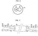
- FIGs. 6 and 7 An example of a device with a distributed pump section is shown in Figs. 6 and 7 .
- the pump source is a multimode optical fiber 62 that is arranged side-by-side with the gain fiber. When these fibers are close enough, energy from the pump fiber transfers to the gain fiber. The phenomenon is well known and has been used for some time in optical couplers.
- Fig. 6 the two side-by-side fibers 61 and 62 are shown with common coating 63.
- More than one pump fiber may be used in an arrangement similar to that shown at the input end of the pump combiner of Fig. 3 .
- Fig. 7 shows the distributed pump embodiment of Fig. 6 with the input and output ends shown.
- the gain section, of which Fig. 6 is a representative cross section, is indicated at 63.
- the amount of gain in the device will be approximately proportional to length of the gain section, i.e., the length along which the fibers are coupled.
- the gain fiber is shown at 61, and carries the optical signal, or lasing mode.
- the pump fiber is shown at 62.
- the modefield diameter is represented by circles 65, 66.
- the adiabatic transformers of the invention are shown at 67 and 68. In this device, two transformers are shown.
- Transformer 67 at the input side, expands the modefield to match the modefield in the gain section.
- the second transformer, 68 is used in reverse to return the modefield pattern to the original shape, or to reduce the modefield pattern if different sized modefield areas (input vs. output) are desired.
- the pump light may propagate in either direction.
- Reference herein to a gain section or a gain device is intended to describe optical fiber means that enhance the power of a traveling lightwave in a fiber.
- the fibers are doped with a rare earth element, typically erbium, or combinations of rare earth elements Er, Nd, Yb, Sm, La, Ce, Pr, Pm, Gd, Tb, Dy, Ho, Tm, Lu.
- a rare earth element typically erbium, or combinations of rare earth elements Er, Nd, Yb, Sm, La, Ce, Pr, Pm, Gd, Tb, Dy, Ho, Tm, Lu.
- Other dopants for example, Al, P, are also frequently present.
Landscapes
- Physics & Mathematics (AREA)
- Electromagnetism (AREA)
- Engineering & Computer Science (AREA)
- Plasma & Fusion (AREA)
- Optics & Photonics (AREA)
- Lasers (AREA)
Applications Claiming Priority (2)
| Application Number | Priority Date | Filing Date | Title |
|---|---|---|---|
| US10/461,133 US6970624B2 (en) | 2003-06-13 | 2003-06-13 | Cladding pumped optical fiber gain devices |
| EP04010943A EP1487070A1 (en) | 2003-06-13 | 2004-05-07 | Cladding-pumped optical fiber gain devices |
Related Parent Applications (2)
| Application Number | Title | Priority Date | Filing Date |
|---|---|---|---|
| EP04010943.1 Division | 2004-05-07 | ||
| EP04010943A Division EP1487070A1 (en) | 2003-06-13 | 2004-05-07 | Cladding-pumped optical fiber gain devices |
Publications (3)
| Publication Number | Publication Date |
|---|---|
| EP2086069A2 EP2086069A2 (en) | 2009-08-05 |
| EP2086069A3 EP2086069A3 (en) | 2009-08-19 |
| EP2086069B1 true EP2086069B1 (en) | 2013-01-16 |
Family
ID=33299769
Family Applications (2)
| Application Number | Title | Priority Date | Filing Date |
|---|---|---|---|
| EP04010943A Withdrawn EP1487070A1 (en) | 2003-06-13 | 2004-05-07 | Cladding-pumped optical fiber gain devices |
| EP09005772A Expired - Lifetime EP2086069B1 (en) | 2003-06-13 | 2004-05-07 | Cladding-pumped optical fiber gain devices |
Family Applications Before (1)
| Application Number | Title | Priority Date | Filing Date |
|---|---|---|---|
| EP04010943A Withdrawn EP1487070A1 (en) | 2003-06-13 | 2004-05-07 | Cladding-pumped optical fiber gain devices |
Country Status (4)
| Country | Link |
|---|---|
| US (1) | US6970624B2 (zh) |
| EP (2) | EP1487070A1 (zh) |
| JP (1) | JP3987840B2 (zh) |
| CN (1) | CN100397124C (zh) |
Families Citing this family (42)
| Publication number | Priority date | Publication date | Assignee | Title |
|---|---|---|---|---|
| US7046875B2 (en) | 2003-10-29 | 2006-05-16 | Itf Technologies Optiques Inc. | Optical coupler comprising multimode fibers and method of making the same |
| US7016573B2 (en) * | 2003-11-13 | 2006-03-21 | Imra America, Inc. | Optical fiber pump multiplexer |
| EP1811616B1 (en) * | 2005-12-16 | 2017-01-04 | OFS Fitel, LLC | Rare-earth-doped, large-mode-area, multimode, hybrid optical fibers and devices using the same |
| JP5173137B2 (ja) * | 2006-01-27 | 2013-03-27 | 株式会社フジクラ | ダブルクラッドファイバ、結合構造、ファイバアンプ及びファイバレーザ |
| US7532792B2 (en) * | 2006-08-28 | 2009-05-12 | Crystal Fibre A/S | Optical coupler, a method of its fabrication and use |
| GB2439345A (en) * | 2006-06-23 | 2007-12-27 | Gsi Group Ltd | Annular tapered fibre coupler for cladding pumping of an optical fibre |
| US7340138B1 (en) * | 2007-01-25 | 2008-03-04 | Furukawa Electric North America, Inc. | Optical fiber devices and methods for interconnecting dissimilar fibers |
| US7916386B2 (en) * | 2007-01-26 | 2011-03-29 | Ofs Fitel, Llc | High power optical apparatus employing large-mode-area, multimode, gain-producing optical fibers |
| US20080267560A1 (en) * | 2007-04-30 | 2008-10-30 | Digiovanni David John | Mode-field resizing in optical fibers |
| US7844146B2 (en) * | 2008-04-30 | 2010-11-30 | Ofs Fitel, Llc | All-fiber module for femtosecond pulse compression and supercontinuum generation |
| US9063289B1 (en) * | 2008-06-30 | 2015-06-23 | Nlight Photonics Corporation | Multimode fiber combiners |
| US8873134B2 (en) | 2008-08-21 | 2014-10-28 | Nlight Photonics Corporation | Hybrid laser amplifier system including active taper |
| US9158070B2 (en) | 2008-08-21 | 2015-10-13 | Nlight Photonics Corporation | Active tapers with reduced nonlinearity |
| US9285541B2 (en) | 2008-08-21 | 2016-03-15 | Nlight Photonics Corporation | UV-green converting fiber laser using active tapers |
| DE102008053728B4 (de) * | 2008-10-29 | 2015-02-26 | Trumpf Laser Gmbh | Optische Faseranordnung |
| JP2010199563A (ja) * | 2009-01-27 | 2010-09-09 | Fujikura Ltd | 光増幅器及び共振器 |
| US8218928B2 (en) * | 2009-04-23 | 2012-07-10 | Ofs Fitel, Llc | Spatial filtering of higher order modes in multimode fibers |
| US9494738B1 (en) | 2009-05-28 | 2016-11-15 | Nlight, Inc. | Single mode fiber combiners |
| US8184363B2 (en) * | 2009-08-07 | 2012-05-22 | Northrop Grumman Systems Corporation | All-fiber integrated high power coherent beam combination |
| US8514485B2 (en) * | 2009-08-07 | 2013-08-20 | Northrop Grumman Systems Corporation | Passive all-fiber integrated high power coherent beam combination |
| US8184361B2 (en) * | 2009-08-07 | 2012-05-22 | Northrop Grumman Systems Corporation | Integrated spectral and all-fiber coherent beam combination |
| JP2011124460A (ja) * | 2009-12-14 | 2011-06-23 | Fujikura Ltd | 光ファイバ出射回路及びファイバレーザ |
| US9484706B1 (en) | 2012-06-12 | 2016-11-01 | Nlight, Inc. | Tapered core fiber manufacturing methods |
| WO2014011846A2 (en) * | 2012-07-12 | 2014-01-16 | The Government Of The United States Of America, As Represented By The Secretary Of The Navy | Wavelength and power scalable waveguiding-based infrared laser system |
| US9366806B2 (en) | 2012-08-29 | 2016-06-14 | Ofs Fitel, Llc | Gain-producing fibers with increased cladding absorption while maintaining single-mode operation |
| US9366810B2 (en) | 2012-08-29 | 2016-06-14 | Ofs Fitel, Llc | Double-clad, gain-producing fibers with increased cladding absoroption while maintaining single-mode operation |
| WO2014105756A1 (en) | 2012-12-31 | 2014-07-03 | Nlight Photonics Corporation | Spatially stable high brightness fiber |
| WO2014105757A1 (en) | 2012-12-31 | 2014-07-03 | Nlight Photonics Corporation | All fiber low dynamic pointing high power lma fiber amplifier |
| US9214781B2 (en) | 2013-11-21 | 2015-12-15 | Lockheed Martin Corporation | Fiber amplifier system for suppression of modal instabilities and method |
| CN103984059B (zh) * | 2014-05-26 | 2016-05-18 | 山东海富光子科技股份有限公司 | 一种基于光纤腐蚀的(n+1)×1光纤端面泵浦合束器 |
| US10069271B2 (en) | 2014-06-02 | 2018-09-04 | Nlight, Inc. | Scalable high power fiber laser |
| US9837783B2 (en) | 2015-01-26 | 2017-12-05 | Nlight, Inc. | High-power, single-mode fiber sources |
| US10050404B2 (en) * | 2015-03-26 | 2018-08-14 | Nlight, Inc. | Fiber source with cascaded gain stages and/or multimode delivery fiber with low splice loss |
| WO2017008022A1 (en) | 2015-07-08 | 2017-01-12 | Nlight, Inc. | Fiber with depressed central index for increased beam parameter product |
| US10730785B2 (en) | 2016-09-29 | 2020-08-04 | Nlight, Inc. | Optical fiber bending mechanisms |
| KR102498030B1 (ko) | 2016-09-29 | 2023-02-08 | 엔라이트 인크. | 조정 가능한 빔 특성 |
| US10673198B2 (en) | 2016-09-29 | 2020-06-02 | Nlight, Inc. | Fiber-coupled laser with time varying beam characteristics |
| US10673199B2 (en) | 2016-09-29 | 2020-06-02 | Nlight, Inc. | Fiber-based saturable absorber |
| US10673197B2 (en) | 2016-09-29 | 2020-06-02 | Nlight, Inc. | Fiber-based optical modulator |
| CN107561635A (zh) * | 2017-10-13 | 2018-01-09 | 中国工程物理研究院激光聚变研究中心 | 渐变吸收系数增益光纤及光学系统 |
| US11287722B2 (en) | 2018-05-14 | 2022-03-29 | Civan Advanced Technologies, Ltd | Laser beams methods and systems |
| CN108879312B (zh) * | 2018-06-20 | 2019-09-17 | 上海卫星工程研究所 | 阳光泵浦光纤激光放大系统 |
Family Cites Families (20)
| Publication number | Priority date | Publication date | Assignee | Title |
|---|---|---|---|---|
| US4553238A (en) | 1983-09-30 | 1985-11-12 | The Board Of Trustees Of The Leland Stanford University | Fiber optic amplifier |
| US4701011A (en) * | 1985-01-15 | 1987-10-20 | American Telephone And Telegraph Company, At&T Bell Laboratories | Multimode fiber-lens optical coupler |
| US4737004A (en) * | 1985-10-03 | 1988-04-12 | American Telephone And Telegraph Company, At&T Bell Laboratories | Expanded end optical fiber and associated coupling arrangements |
| JP2955780B2 (ja) * | 1991-06-27 | 1999-10-04 | 三菱電線工業株式会社 | 光ファイバ増幅器 |
| US5418880A (en) | 1994-07-29 | 1995-05-23 | Polaroid Corporation | High-power optical fiber amplifier or laser device |
| JP3298799B2 (ja) | 1995-11-22 | 2002-07-08 | ルーセント テクノロジーズ インコーポレイテッド | クラッディングポンプファイバとその製造方法 |
| US5892615A (en) * | 1997-03-17 | 1999-04-06 | Sdl, Inc. | Output power enhancement in optical fiber lasers |
| US6014389A (en) | 1997-03-24 | 2000-01-11 | The United States Of America As Represented By The Secretary Of The Air Force | Fiber-based continuous wave blue laser source |
| US6606446B1 (en) * | 1997-05-19 | 2003-08-12 | Jds Uniphase Corporation | Miniature variable attenuator |
| US5864644A (en) * | 1997-07-21 | 1999-01-26 | Lucent Technologies Inc. | Tapered fiber bundles for coupling light into and out of cladding-pumped fiber devices |
| US5937134A (en) | 1997-08-07 | 1999-08-10 | Lucent Technologies Inc. | Cladding pumped fiber lasers |
| WO1999045419A1 (en) * | 1998-03-04 | 1999-09-10 | Sdl, Inc. | Optical couplers for multimode fibers |
| US6043929A (en) * | 1998-03-16 | 2000-03-28 | Lucent Technologies, Inc. | Adiabatic waveguide amplifier |
| KR100276968B1 (ko) * | 1998-07-11 | 2001-01-15 | 윤덕용 | 정렬 허용공차를 확대시킬 수 있는 광 연결구조 |
| US6597711B2 (en) * | 1998-12-04 | 2003-07-22 | Cidra Corporation | Bragg grating-based laser |
| CA2326980A1 (en) * | 1999-12-02 | 2001-06-02 | Jds Uniphase Inc. | Low cost amplifier using bulk optics |
| US6411757B1 (en) * | 2000-02-14 | 2002-06-25 | Agere Systems Guardian Corp. | Article comprising a waveguide structure with improved pump utilization |
| JP2002006169A (ja) * | 2000-06-27 | 2002-01-09 | Central Glass Co Ltd | 光増幅ファイバモジュール |
| EP1260841B1 (en) * | 2001-05-19 | 2007-07-11 | Lucent Technologies Inc. | GRIN fiber lenses |
| JP2004530927A (ja) * | 2001-06-15 | 2004-10-07 | コーニング インコーポレイテッド | 集束及び集光器用のテーパ型レンズ付ファイバ |
-
2003
- 2003-06-13 US US10/461,133 patent/US6970624B2/en not_active Expired - Lifetime
-
2004
- 2004-05-07 EP EP04010943A patent/EP1487070A1/en not_active Withdrawn
- 2004-05-07 EP EP09005772A patent/EP2086069B1/en not_active Expired - Lifetime
- 2004-06-11 CN CNB2004100490740A patent/CN100397124C/zh active Active
- 2004-06-11 JP JP2004173272A patent/JP3987840B2/ja active Active
Also Published As
| Publication number | Publication date |
|---|---|
| JP3987840B2 (ja) | 2007-10-10 |
| CN100397124C (zh) | 2008-06-25 |
| JP2005005717A (ja) | 2005-01-06 |
| US20040252946A1 (en) | 2004-12-16 |
| CN1617003A (zh) | 2005-05-18 |
| EP1487070A1 (en) | 2004-12-15 |
| EP2086069A3 (en) | 2009-08-19 |
| US6970624B2 (en) | 2005-11-29 |
| EP2086069A2 (en) | 2009-08-05 |
Similar Documents
| Publication | Publication Date | Title |
|---|---|---|
| EP2086069B1 (en) | Cladding-pumped optical fiber gain devices | |
| US7046432B2 (en) | Optical fiber coupling arrangement | |
| EP2791719B1 (en) | Multi-core erbium-doped fiber amplifier | |
| US6608951B1 (en) | Optical fiber amplifiers and lasers and optical pumping device therefor | |
| EP1060423B1 (en) | Optical couplers for multimode fibers | |
| US6987783B2 (en) | Three-level air-clad rare-earth doped fiber laser/amplifier | |
| EP1636883B1 (en) | Multiple emitter side-pumping method and apparatus for fiber lasers | |
| US6324326B1 (en) | Tapered fiber laser | |
| US9025239B2 (en) | Multi-core erbium-doped fiber amplifier | |
| EP0802592A2 (en) | High power optical fiber amplifier/laser system | |
| EP1988412A2 (en) | Mode-field resizing in optical fibers | |
| EP0723714A1 (en) | A high power optical fiber amplifier pumped by a multi-mode laser source | |
| JPH11136193A (ja) | 光増幅器のマルチモード・ポンピングのためのモード・スクランブリングを有するツイン結合器 | |
| Mélin et al. | Power efficient all-fiberized 12-core erbium/ytterbium doped optical amplifier | |
| US9768581B2 (en) | Pump and signal combiner for high numerical aperture use | |
| US9322993B1 (en) | All pump combiner with cladless inputs | |
| Headley III et al. | Tapered fiber bundles for combining laser pumps | |
| Simonneau et al. | High-power air-clad photonic crystal fiber cladding-pumped EDFA for WDM applications in the C-band | |
| US9362709B1 (en) | Optical fiber laser architecture with partitioned pump and signal coupling | |
| US9595803B2 (en) | Fat-fiber adapter for pump use | |
| EP0899834A1 (en) | Twin coupler with mode scrambling for multimode pumping of optical amplifiers | |
| EP4359833A1 (en) | Super-mode selective optical unit |
Legal Events
| Date | Code | Title | Description |
|---|---|---|---|
| PUAI | Public reference made under article 153(3) epc to a published international application that has entered the european phase |
Free format text: ORIGINAL CODE: 0009012 |
|
| PUAL | Search report despatched |
Free format text: ORIGINAL CODE: 0009013 |
|
| AC | Divisional application: reference to earlier application |
Ref document number: 1487070 Country of ref document: EP Kind code of ref document: P |
|
| AK | Designated contracting states |
Kind code of ref document: A2 Designated state(s): DE FR GB IT |
|
| RIC1 | Information provided on ipc code assigned before grant |
Ipc: H01S 3/067 20060101AFI20090630BHEP |
|
| AK | Designated contracting states |
Kind code of ref document: A3 Designated state(s): DE FR GB IT |
|
| RIN1 | Information on inventor provided before grant (corrected) |
Inventor name: DIGIOVANNI, DAVID J. Inventor name: YABLON, ANDREW D. |
|
| 17P | Request for examination filed |
Effective date: 20100219 |
|
| R17P | Request for examination filed (corrected) |
Effective date: 20100219 |
|
| 17Q | First examination report despatched |
Effective date: 20100426 |
|
| GRAP | Despatch of communication of intention to grant a patent |
Free format text: ORIGINAL CODE: EPIDOSNIGR1 |
|
| GRAS | Grant fee paid |
Free format text: ORIGINAL CODE: EPIDOSNIGR3 |
|
| GRAA | (expected) grant |
Free format text: ORIGINAL CODE: 0009210 |
|
| AC | Divisional application: reference to earlier application |
Ref document number: 1487070 Country of ref document: EP Kind code of ref document: P |
|
| AK | Designated contracting states |
Kind code of ref document: B1 Designated state(s): DE FR GB IT |
|
| REG | Reference to a national code |
Ref country code: GB Ref legal event code: FG4D |
|
| REG | Reference to a national code |
Ref country code: DE Ref legal event code: R096 Ref document number: 602004040826 Country of ref document: DE Effective date: 20130314 |
|
| PLBE | No opposition filed within time limit |
Free format text: ORIGINAL CODE: 0009261 |
|
| STAA | Information on the status of an ep patent application or granted ep patent |
Free format text: STATUS: NO OPPOSITION FILED WITHIN TIME LIMIT |
|
| 26N | No opposition filed |
Effective date: 20131017 |
|
| REG | Reference to a national code |
Ref country code: DE Ref legal event code: R097 Ref document number: 602004040826 Country of ref document: DE Effective date: 20131017 |
|
| REG | Reference to a national code |
Ref country code: FR Ref legal event code: PLFP Year of fee payment: 13 |
|
| REG | Reference to a national code |
Ref country code: FR Ref legal event code: PLFP Year of fee payment: 14 |
|
| REG | Reference to a national code |
Ref country code: FR Ref legal event code: PLFP Year of fee payment: 15 |
|
| P01 | Opt-out of the competence of the unified patent court (upc) registered |
Effective date: 20230411 |
|
| PGFP | Annual fee paid to national office [announced via postgrant information from national office to epo] |
Ref country code: IT Payment date: 20230921 Year of fee payment: 20 Ref country code: GB Payment date: 20230828 Year of fee payment: 20 |
|
| PGFP | Annual fee paid to national office [announced via postgrant information from national office to epo] |
Ref country code: FR Payment date: 20230825 Year of fee payment: 20 Ref country code: DE Payment date: 20230829 Year of fee payment: 20 |
|
| REG | Reference to a national code |
Ref country code: DE Ref legal event code: R071 Ref document number: 602004040826 Country of ref document: DE |