EP2086025A1 - Lay-up apparatus - Google Patents
Lay-up apparatus Download PDFInfo
- Publication number
- EP2086025A1 EP2086025A1 EP09001244A EP09001244A EP2086025A1 EP 2086025 A1 EP2086025 A1 EP 2086025A1 EP 09001244 A EP09001244 A EP 09001244A EP 09001244 A EP09001244 A EP 09001244A EP 2086025 A1 EP2086025 A1 EP 2086025A1
- Authority
- EP
- European Patent Office
- Prior art keywords
- tape
- strip
- strips
- lay
- moving means
- Prior art date
- Legal status (The legal status is an assumption and is not a legal conclusion. Google has not performed a legal analysis and makes no representation as to the accuracy of the status listed.)
- Granted
Links
Images




Classifications
-
- B—PERFORMING OPERATIONS; TRANSPORTING
- B65—CONVEYING; PACKING; STORING; HANDLING THIN OR FILAMENTARY MATERIAL
- B65H—HANDLING THIN OR FILAMENTARY MATERIAL, e.g. SHEETS, WEBS, CABLES
- B65H35/00—Delivering articles from cutting or line-perforating machines; Article or web delivery apparatus incorporating cutting or line-perforating devices, e.g. adhesive tape dispensers
- B65H35/0006—Article or web delivery apparatus incorporating cutting or line-perforating devices
- B65H35/006—Article or web delivery apparatus incorporating cutting or line-perforating devices with means for delivering a predetermined length of tape
- B65H35/0066—Article or web delivery apparatus incorporating cutting or line-perforating devices with means for delivering a predetermined length of tape this length being adjustable
-
- H—ELECTRICITY
- H10—SEMICONDUCTOR DEVICES; ELECTRIC SOLID-STATE DEVICES NOT OTHERWISE PROVIDED FOR
- H10P—GENERIC PROCESSES OR APPARATUS FOR THE MANUFACTURE OR TREATMENT OF DEVICES COVERED BY CLASS H10
- H10P72/00—Handling or holding of wafers, substrates or devices during manufacture or treatment thereof
- H10P72/50—Handling or holding of wafers, substrates or devices during manufacture or treatment thereof for positioning, orientation or alignment
-
- B—PERFORMING OPERATIONS; TRANSPORTING
- B65—CONVEYING; PACKING; STORING; HANDLING THIN OR FILAMENTARY MATERIAL
- B65H—HANDLING THIN OR FILAMENTARY MATERIAL, e.g. SHEETS, WEBS, CABLES
- B65H35/00—Delivering articles from cutting or line-perforating machines; Article or web delivery apparatus incorporating cutting or line-perforating devices, e.g. adhesive tape dispensers
- B65H35/0006—Article or web delivery apparatus incorporating cutting or line-perforating devices
- B65H35/002—Hand-held or table apparatus
- B65H35/0026—Hand-held or table apparatus for delivering pressure-sensitive adhesive tape
- B65H35/0033—Hand-held or table apparatus for delivering pressure-sensitive adhesive tape and affixing it to a surface
-
- H—ELECTRICITY
- H10—SEMICONDUCTOR DEVICES; ELECTRIC SOLID-STATE DEVICES NOT OTHERWISE PROVIDED FOR
- H10F—INORGANIC SEMICONDUCTOR DEVICES SENSITIVE TO INFRARED RADIATION, LIGHT, ELECTROMAGNETIC RADIATION OF SHORTER WAVELENGTH OR CORPUSCULAR RADIATION
- H10F10/00—Individual photovoltaic cells, e.g. solar cells
-
- H—ELECTRICITY
- H10—SEMICONDUCTOR DEVICES; ELECTRIC SOLID-STATE DEVICES NOT OTHERWISE PROVIDED FOR
- H10F—INORGANIC SEMICONDUCTOR DEVICES SENSITIVE TO INFRARED RADIATION, LIGHT, ELECTROMAGNETIC RADIATION OF SHORTER WAVELENGTH OR CORPUSCULAR RADIATION
- H10F71/00—Manufacture or treatment of devices covered by this subclass
- H10F71/137—Batch treatment of the devices
- H10F71/1375—Apparatus for automatic interconnection of photovoltaic cells in a module
-
- Y—GENERAL TAGGING OF NEW TECHNOLOGICAL DEVELOPMENTS; GENERAL TAGGING OF CROSS-SECTIONAL TECHNOLOGIES SPANNING OVER SEVERAL SECTIONS OF THE IPC; TECHNICAL SUBJECTS COVERED BY FORMER USPC CROSS-REFERENCE ART COLLECTIONS [XRACs] AND DIGESTS
- Y02—TECHNOLOGIES OR APPLICATIONS FOR MITIGATION OR ADAPTATION AGAINST CLIMATE CHANGE
- Y02E—REDUCTION OF GREENHOUSE GAS [GHG] EMISSIONS, RELATED TO ENERGY GENERATION, TRANSMISSION OR DISTRIBUTION
- Y02E10/00—Energy generation through renewable energy sources
- Y02E10/50—Photovoltaic [PV] energy
-
- Y—GENERAL TAGGING OF NEW TECHNOLOGICAL DEVELOPMENTS; GENERAL TAGGING OF CROSS-SECTIONAL TECHNOLOGIES SPANNING OVER SEVERAL SECTIONS OF THE IPC; TECHNICAL SUBJECTS COVERED BY FORMER USPC CROSS-REFERENCE ART COLLECTIONS [XRACs] AND DIGESTS
- Y10—TECHNICAL SUBJECTS COVERED BY FORMER USPC
- Y10T—TECHNICAL SUBJECTS COVERED BY FORMER US CLASSIFICATION
- Y10T156/00—Adhesive bonding and miscellaneous chemical manufacture
- Y10T156/10—Methods of surface bonding and/or assembly therefor
- Y10T156/1052—Methods of surface bonding and/or assembly therefor with cutting, punching, tearing or severing
- Y10T156/1084—Methods of surface bonding and/or assembly therefor with cutting, punching, tearing or severing of continuous or running length bonded web
-
- Y—GENERAL TAGGING OF NEW TECHNOLOGICAL DEVELOPMENTS; GENERAL TAGGING OF CROSS-SECTIONAL TECHNOLOGIES SPANNING OVER SEVERAL SECTIONS OF THE IPC; TECHNICAL SUBJECTS COVERED BY FORMER USPC CROSS-REFERENCE ART COLLECTIONS [XRACs] AND DIGESTS
- Y10—TECHNICAL SUBJECTS COVERED BY FORMER USPC
- Y10T—TECHNICAL SUBJECTS COVERED BY FORMER US CLASSIFICATION
- Y10T156/00—Adhesive bonding and miscellaneous chemical manufacture
- Y10T156/10—Methods of surface bonding and/or assembly therefor
- Y10T156/1089—Methods of surface bonding and/or assembly therefor of discrete laminae to single face of additional lamina
- Y10T156/1092—All laminae planar and face to face
-
- Y—GENERAL TAGGING OF NEW TECHNOLOGICAL DEVELOPMENTS; GENERAL TAGGING OF CROSS-SECTIONAL TECHNOLOGIES SPANNING OVER SEVERAL SECTIONS OF THE IPC; TECHNICAL SUBJECTS COVERED BY FORMER USPC CROSS-REFERENCE ART COLLECTIONS [XRACs] AND DIGESTS
- Y10—TECHNICAL SUBJECTS COVERED BY FORMER USPC
- Y10T—TECHNICAL SUBJECTS COVERED BY FORMER US CLASSIFICATION
- Y10T156/00—Adhesive bonding and miscellaneous chemical manufacture
- Y10T156/12—Surface bonding means and/or assembly means with cutting, punching, piercing, severing or tearing
-
- Y—GENERAL TAGGING OF NEW TECHNOLOGICAL DEVELOPMENTS; GENERAL TAGGING OF CROSS-SECTIONAL TECHNOLOGIES SPANNING OVER SEVERAL SECTIONS OF THE IPC; TECHNICAL SUBJECTS COVERED BY FORMER USPC CROSS-REFERENCE ART COLLECTIONS [XRACs] AND DIGESTS
- Y10—TECHNICAL SUBJECTS COVERED BY FORMER USPC
- Y10T—TECHNICAL SUBJECTS COVERED BY FORMER US CLASSIFICATION
- Y10T156/00—Adhesive bonding and miscellaneous chemical manufacture
- Y10T156/12—Surface bonding means and/or assembly means with cutting, punching, piercing, severing or tearing
- Y10T156/125—Plural severing means each acting on a different work piece
-
- Y—GENERAL TAGGING OF NEW TECHNOLOGICAL DEVELOPMENTS; GENERAL TAGGING OF CROSS-SECTIONAL TECHNOLOGIES SPANNING OVER SEVERAL SECTIONS OF THE IPC; TECHNICAL SUBJECTS COVERED BY FORMER USPC CROSS-REFERENCE ART COLLECTIONS [XRACs] AND DIGESTS
- Y10—TECHNICAL SUBJECTS COVERED BY FORMER USPC
- Y10T—TECHNICAL SUBJECTS COVERED BY FORMER US CLASSIFICATION
- Y10T156/00—Adhesive bonding and miscellaneous chemical manufacture
- Y10T156/12—Surface bonding means and/or assembly means with cutting, punching, piercing, severing or tearing
- Y10T156/13—Severing followed by associating with part from same source
-
- Y—GENERAL TAGGING OF NEW TECHNOLOGICAL DEVELOPMENTS; GENERAL TAGGING OF CROSS-SECTIONAL TECHNOLOGIES SPANNING OVER SEVERAL SECTIONS OF THE IPC; TECHNICAL SUBJECTS COVERED BY FORMER USPC CROSS-REFERENCE ART COLLECTIONS [XRACs] AND DIGESTS
- Y10—TECHNICAL SUBJECTS COVERED BY FORMER USPC
- Y10T—TECHNICAL SUBJECTS COVERED BY FORMER US CLASSIFICATION
- Y10T156/00—Adhesive bonding and miscellaneous chemical manufacture
- Y10T156/12—Surface bonding means and/or assembly means with cutting, punching, piercing, severing or tearing
- Y10T156/1317—Means feeding plural workpieces to be joined
-
- Y—GENERAL TAGGING OF NEW TECHNOLOGICAL DEVELOPMENTS; GENERAL TAGGING OF CROSS-SECTIONAL TECHNOLOGIES SPANNING OVER SEVERAL SECTIONS OF THE IPC; TECHNICAL SUBJECTS COVERED BY FORMER USPC CROSS-REFERENCE ART COLLECTIONS [XRACs] AND DIGESTS
- Y10—TECHNICAL SUBJECTS COVERED BY FORMER USPC
- Y10T—TECHNICAL SUBJECTS COVERED BY FORMER US CLASSIFICATION
- Y10T156/00—Adhesive bonding and miscellaneous chemical manufacture
- Y10T156/12—Surface bonding means and/or assembly means with cutting, punching, piercing, severing or tearing
- Y10T156/1317—Means feeding plural workpieces to be joined
- Y10T156/1322—Severing before bonding or assembling of parts
-
- Y—GENERAL TAGGING OF NEW TECHNOLOGICAL DEVELOPMENTS; GENERAL TAGGING OF CROSS-SECTIONAL TECHNOLOGIES SPANNING OVER SEVERAL SECTIONS OF THE IPC; TECHNICAL SUBJECTS COVERED BY FORMER USPC CROSS-REFERENCE ART COLLECTIONS [XRACs] AND DIGESTS
- Y10—TECHNICAL SUBJECTS COVERED BY FORMER USPC
- Y10T—TECHNICAL SUBJECTS COVERED BY FORMER US CLASSIFICATION
- Y10T156/00—Adhesive bonding and miscellaneous chemical manufacture
- Y10T156/12—Surface bonding means and/or assembly means with cutting, punching, piercing, severing or tearing
- Y10T156/1348—Work traversing type
-
- Y—GENERAL TAGGING OF NEW TECHNOLOGICAL DEVELOPMENTS; GENERAL TAGGING OF CROSS-SECTIONAL TECHNOLOGIES SPANNING OVER SEVERAL SECTIONS OF THE IPC; TECHNICAL SUBJECTS COVERED BY FORMER USPC CROSS-REFERENCE ART COLLECTIONS [XRACs] AND DIGESTS
- Y10—TECHNICAL SUBJECTS COVERED BY FORMER USPC
- Y10T—TECHNICAL SUBJECTS COVERED BY FORMER US CLASSIFICATION
- Y10T156/00—Adhesive bonding and miscellaneous chemical manufacture
- Y10T156/17—Surface bonding means and/or assemblymeans with work feeding or handling means
- Y10T156/1702—For plural parts or plural areas of single part
- Y10T156/1705—Lamina transferred to base from adhered flexible web or sheet type carrier
Definitions
- the present invention relates to a technique of laying a thin and band-shaped tape, and particularly to a technique of laying a copper foil and an insulation tape for use in a thin film-type photovoltaic devices.
- a photovoltaic devices which converts solar energy into electric energy.
- a crystalline photovoltaic devices is a configuration in which a single- crystalline or poly-crystalline silicon substrate is used. The crystalline photovoltaic cell is a currently dominant but is expensive.
- a thin film-type photovoltaic devices is formed by depositing thin film-type amorphous silicon on, for example, a glass substrate or the like.
- CIS non-silicon thin film-type photovoltaic devices
- a thin film-type photovoltaic devices panel is configured with a structure that plural photovoltaic cells are electrically series-connected in one transparent electrode substrate.
- FIG. 7 shows a structure of the thin film-type photovoltaic devices panel.
- a thin film-type photovoltaic devices panel 1 includes plural photovoltaic cells 2 and a peripheral area 3 surrounding the plural photovoltaic cells 2.
- the plural photovoltaic cells 2 and the peripheral area 3 are insulated each other.
- Each photovoltaic cell 2 is formed into an elongated rectangular shape along a long side of the photovoltaic devices panel 1, and one of the long sides is an anode and the other is a cathode. Accordingly, the photovoltaic devices panel 1 is configured with the structure that the plural photovoltaic cells 2 are series-connected.
- a copper-foil electrode 5 having substantially the same length as the photovoltaic cell 2 is attached to the photovoltaic cell 2 located at the left end of the photovoltaic devices panel 1.
- a copper-foil electrode 6 having substantially the same length as the photovoltaic cell 2 is attached to the photovoltaic cell 2 located at the right end of the photovoltaic devices panel 1.
- the plural series-connected photovoltaic cells 2 becomes a direct-current power supply when the electrodes 5 and 6 are connected to a load.
- the electrodes 5 and 6 are connected to a central junction box 11 via conductors 7 and 8, and the junction box 11 is connected to a connector of load (not shown) to use an electric power generated from the photovoltaic devices panel 1.
- the copper-foil conductor 7 extends from the electrode 5 toward the junction box 11, and the conductor 8 extends from the electrode 6 toward the junction box 11. Because the conductors 7 and 8 are conductive materials, a short circuit occurs when the conductors 7 and 8 directly contact the photovoltaic cells 2 located between the electrode 5 and electrode 6. Therefore, insulation tapes 9 and 10 are laid between the conductor 7 and the photovoltaic cells 2 and between the conductor 8 and the photovoltaic cells 2, respectively.
- FIG. 8 is an enlarged view of a part of FIG. 7 and shows the relationship A between the electrode 5, the conductor 7, and the insulation tape 9.
- the relationship A holds true for the relationship B between the electrode 6, the conductor 8, and the insulation tape 10.
- the relationship B is described by that the electrode 5 can be replaced for the electrode 6, the conductor 7 can be replaced for the conductor 8, and the insulation tape 9 can be replaced for the insulation tape 10 in the description of the relationship A. Therefore the description thereof is omitted in the following description.
- the part having a width W of photovoltaic cell 2 at the left end is exposed on one side.
- the conductor 7 must be connected to the electrode 5, but needs to be electrically insulated from the adjacent photovoltaic cell 2. Therefore, it is necessary that an end 9a of the insulation tape 9 intrude into the part having a width W of photovoltaic cell 2 at the left end , and it is necessary that the relationship of d ⁇ W hold, where d is a gap between the end 9a and the electrode 5.
- the photovoltaic cell 2 has a width of about 5 to 6 mm.
- the photovoltaic devices panel 1 has a width of about 1000 mm, and the conductor 7 or the insulation tape 9 has a length of about 400 mm.
- the accuracy of cutting the conductor 7 or the insulation tape 9 is important to above demands, while only the width W is very narrow, ranging from about 1 to 2 mm. Therefore, the relationship of d ⁇ W cannot be secured unless a position at which the conductor 7 or the insulation tape 9 is laid is accurately determined, and the problem above can hardly be solved.
- an object of the invention is to provide a lay-up apparatus with which the tape such as the copper foil and the insulation tape can accurately be positioned and bonded even if a fluctuation in length exists in the cut tape.
- a lay-up apparatus for laying tape between two strips of material laid on a flat panel separate from but parallel to each other so that the tape extends from each strip of material toward the other strip of material.
- the lay-up apparatus includes a movable gripper to grip the tape to unwind the tape from a reel around which the tape is wound; a cutter to cut the tape when the gripper unwinds a predetermined length of tape from the reel; and moving means capable of three-dimensional movement while supporting the cut tape.
- the moving means is rotatable about an axis perpendicular to the flat panel, and is configured to grip and rotate the tape in opposite directions when laying the tape from one of the two parallel strips of material toward the other of the two parallel strips of material and when laying the tape from the other of the two parallel strips of material toward the one of the two parallel strips of material, so as to keep constant relative positions of one end of the tape serving as a reference point and that strip of material of the two parallel strips of material which is nearer the end of the tape serving as a reference point.
- the lay-up apparatus may be provided with the moving means which may include a vacuum chuck, and suctionally grip the tape with the vacuum chuck.
- the lay-up apparatus may be provided with a supporting cradle that is reciprocally vertically movable and configured to suctionally support the cut tape from below when the cutter cuts the tape.
- the lay-up apparatus may include a second tape laid parallel to the tape; a second movable gripper to grip the second tape to unwind the second tape from a second reel around which the second tape is wound; and a second cutter to cut the second tape when the second gripper unwinds a predetermined length of the second tape from the second reel, wherein the moving means grips the second tape and the tape while laying the tape below the second tape.
- the lay-up apparatus may be configured so that the flat panel is a photovoltaic devices panel in which a thin film of photovoltaic cells is formed on a glass substrate; the strips of material are electrodes provided on the photovoltaic devices panel; the tape is insulation tape; and the second tape is a conductor that connects the electrodes.
- tape is laid as follows:
- the lay-up apparatus is provided with tape such as insulation tape and a conductor wound around a reel.
- the lay-up apparatus includes a movable gripper, and the movable gripper unwinds the tape while gripping an end portion of the tape.
- the movable gripper reaches a predetermined position, the tape is cut with a cutter because the tape is unwound to the predetermined length.
- the cut tape is gripped by the moving means while the tape (conductor) and the insulation tape overlap each other, and the cut tape is then moved near the photovoltaic devices panel 1.
- the conductor 7 and the insulation tape 9 are transported by the moving means while rotating from point A to A1 around point O in FIG.6A because the conductor 7 and the insulation tape 9 are orientated as shown in FIG. 7 .
- the conductor 8 and the insulation tape 10 are transported by the moving means while rotating from point A to A2 around point O in FIG.6A because the conductor 8 and the insulation tape 10 are orientated as shown in FIG. 7 .
- a rotating direction in bonding the conductor 7 and the insulation tape 9 and a rotating direction in bonding the conductor 8 and the insulation tape 10 are reversed each other.
- the position of the moving means is accurately determined, so that the position of the tape gripped by the moving means can be determined such that the end serving as a reference point (end) becomes the end 9a of the insulation tape of FIG. 8 . Because the insulation tape 10 is orientated toward the direction opposite to the insulation tape 9, the end position close to the electrode 6 can correctly be determined by reversely rotating the moving means.
- the supporting cradle When the tape is cut with the cutter, the supporting cradle is provided, and the tape is sucked by the supporting cradle. Therefore, undulation of the tape can be prevented and the tape is supported in the straight state.
- the moving means sucks the tape with the vacuum chuck, the tape can be moved in the straight state without damaging the tape during transporting.
- FIG. 1 is a plan view showing a configuration of a lay-up apparatus according to an embodiment of the invention.
- FIG. 2 is an enlarged view showing a main part M of the lay-up apparatus shown in FIG. 1
- FIG. 3 is a front view of the lay-up apparatus shown in FIG. 2 .
- a lay-up apparatus 100 includes a first reel holder 110 that holds a first strip of tape 101, a second reel holder 120 that holds a second strip of tape 102, a moving means 130, an X-axis rail 141 along which the moving means 130 moves, two Y-axis rails 142 that support the moving means 130 at both ends and move together with the moving means 130, and a conveyer 150 that transports a photovoltaic devices panel 1.
- the moving means 130 is also capable of moving in the direction of a Z axis that lies orthogonal to the plane of the paper on which the figures are drawn.
- the first reel holder 110 holds a reel around which the first strip of tape 101 is wound.
- the strip of tape 101 is insulation tape 9, 10.
- the first reel holder 110 is provided with a first fixed gripper 111, a first movable gripper 112, and a first cutter 113 disposed therebetween.
- the first fixed gripper 111 is fixed at a predetermined position, and alternately grips and releases the first strip of tape 101.
- the conductors 7, 8 are copper foil, that is, a thin strip of copper.
- the second reel holder 120 is also provided with a second fixed gripper 121, a second movable gripper 122, and a second cutter 123 disposed therebetween.
- a photovoltaic devices panel 1 is placed on the conveyer 150, transported from the left in FIG. 1 , and stopped at a predetermined position shown in the drawing. Electrodes 5, 6 are attached to the photovoltaic devices panel 1 in a preceding manufacturing step. The same copper foil that is used for the conductors 7, 8 is also used for the electrodes 5, 6. Although the electrodes 5, 6 are fixed on the photovoltaic cells 2 of the photovoltaic devices panel 1, they are not permanently fixed in place but instead are only provisionally fixed in place as described below.
- the first movable gripper 112 moves toward the reel of the first strip of tape 101 at the left in FIG. 1 , grips the ends of the first strip of tape 101, and moves to the right in FIG. 1 to unwind a predetermined length of the first strip of tape 101 from the reel.
- the length of first strip of tape 101 unwound from the reel can be determined with precision.
- the first fixed gripper 111 clamps the first strip of tape 101 from above and below and holds it.
- the first cutter 113 descends and cuts the first strip of tape 101 to a desired length.
- variations do appear in the length of the first strip of tape 101 depending on how much of the first strip of tape 101 the first movable gripper 112 grips.
- a first cradle 115 that is capable of reciprocal vertical movement is provided beneath the first cutter 113 and the first movable gripper 112.
- the first cradle 115 is provided with multiple vacuum holes 115a in order to suctionally attract and vacuum-attach the first strip of tape 101 to the first cradle 115.
- the cut first strip of tape 101 has a tendency to curl because it has just been unwound from the reel, it is set on top of the ascending first cradle 115 and sucked onto the top surface of the first cradle 115 by the vacuum force exerted through the vacuum holes 115a, removing the curl and enabling the first strip of tape 101 to be held straight.
- the second movable gripper 122 moves toward the reel holding the second strip of tape 102, grips the end of the second strip of tape 102, and moves to the right in FIG. 1 to unwind a predetermined length of the second strip of tape 102 from the reel.
- the length of second strip of tape 102 unwound from the reel can be determined with precision.
- the second fixed gripper 121 clamps the second strip of tape 102 from above and below and holds it.
- the second cutter 123 descends and cuts the second strip of tape 102 at a desired length.
- the length of the second strip of tape 102 is set to be slightly longer than the length of the first strip of tape 101.
- variations (tolerances) do appear in the length of the second strip of tape 102 depending on how much of the second strip of tape 102 the second movable gripper 122 grips.
- a second cradle 125 identical in structure to the first cradle 115 is provided beneath the second cutter 123 and the second movable gripper 122.
- the second cradle ascends and the second strip of tape 102 is vacuum-attached to the top of the second cradle 125.
- FIGS. 4A to 4C show one of a plurality of vacuum chucks 132 with which the moving means 130 is provided, in which FIG. 4A shows a state in which only the second strip of tape 102 is vacuum-attached, FIG. 4B shows a state in which both the first strip of tape 101 and the second strip of tape 102 are vacuum-attached, and FIG. 4C shows a bottom surface of the vacuum chuck 132.
- a vacuum hole 132a is provided in the center of the vacuum chuck 132 and two more vacuum holes 132b are provided on either side of the vacuum hole 132a in the center.
- the vacuum hole 132a in the center and the vacuum holes 132b on both sides are configured so as to be capable of independent control, that is, starting suction and stopping suction independently.
- the moving means 130 moves horizontally to a position above the second cradle 125 and descends onto the second strip of tape 102, the vacuum hole 132a in the center of each one of all the plurality of vacuum chucks starts suction to create a vacuum that causes the second strip of tape 102 on top of the second cradle 125 to become vacuum-attached to the moving means 130.
- the suction of the second cradle 125 is stopped, the second strip of tape 102 is gripped solely by the moving means 130 as shown in FIG. 4A .
- the moving means 130 gripping the second strip of tape 102 ascends along the Z axis and then moves horizontally to a position above the first cradle 115, where it descends onto the first strip of tape 101.
- FIG. 5 shows a lateral view of the first strip of tape 101 and the second strip of tape 102 gripped by the moving means 130.
- the cut end of the first strip of tape 101 cut by the first cutter 113 is 101a, and the end gripped by the first movable gripper 112 is 101b.
- the cut end of the second strip of tape 102 cut by the second cutter 123 is 102a, and the end gripped by the second movable gripper 122 is 102b.
- the second cut end 102a projects beyond the first cut end 101a by a length S.
- errors in length appear on the side of the first gripped end 101b and the second gripped end 102b.
- the way in which the difference S described above is set is not limited to any particular method, and can, for example, be set by offsetting the positions of the first cutter 113 and the second cutter 123 along the X axis.
- the conductor 7 and the electrode 5 can be overlaid and at the same time the insulation tape 9 can be separated from the electrode 5 by the distance d as shown in FIG. 8 .
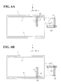
- FIGS. 6A and 6B illustrate how the first strip of tape 101 and the second strip of tape 102 gripped by the moving means 130 are moved over the photovoltaic devices panel 1.
- FIG. 6A shows a situation in which the first strip of tape 101 and the second strip of tape 102 correspond to the insulation tape 9 and the conductor 7, respectively
- FIG. 6B illustrates a situation in which the first strip of tape 101 and the second strip of tape 102 correspond to the insulation tape 10 and the conductor 8, respectively.
- the moving means 130 ascends along the Z axis while gripping the first strip of tape 101 and the second strip of tape 102 in a state in which the first strip of tape 101 overlays the second strip of tape 102, moves within an X-Y plane (horizontal plane), and places a center O of a rotary axis 131 of the moving means 130 at a predetermined particular set of coordinates within the X-Y plane.
- the relative positions of a central point A of the end 101a and the center O of the rotary axis 131 remain constant. Since the coordinates of the center O are known, it is possible to obtain by calculation the coordinates of point A.
- the moving means 130 is rotated about the center O of the rotary axis 131.
- the moving means is rotated clockwise as shown by the solid line in FIG. 6A .
- the position of point A after the moving means 130 is rotated in the direction of the solid line moves to A1.
- the moving means 130 is rotated counterclockwise as shown by the dotted line in FIG. 6B .
- the position of point A after the moving means 130 is rotated in the direction of the dotted line moves to A2.
- both angles of rotation are 90 degrees, it is to be noted that the angles of rotation are not limited to 90 degrees.
- the distance between point O and point A is known, as is the angle of rotation, and therefore it is possible to calculate the coordinates of points A1 and A2. Then, by moving the moving means 130 so that points A1 and A2 coincide with points B1 and B2, respectively, the lay-up positions of the first strip of tape 101 and the second strip of tape 102 can be determined precisely.
- the point A which serves as a reference point is positioned at the center of the end of the first strip of tape 101.
- the reference point A may be set at another point, such as the center of the end of the second strip of tape 102.
- the first strip of tape 101 and the second strip of tape 102 may be laid separately on the photovoltaic devices panel 1 one strip at a time, in which case the reference point A is set on each of the first strip of tape 101 and the second strip of tape 102, respectively. By laying the tape in this way, the relative positions of the electrodes 5, 6 and the first and second strips of tape 101, 102 can be kept constant.
- the conductors 7, 8 and the insulation tape 9, 10 are placed on the photovoltaic devices panel 1 as described above, although not shown in the drawings the conductors 7, 8 and the insulation tape 9, 10 are provisionally fixed in place at multiple locations with adhesive tape and the conductors 7, 8 are bent at right angles at appropriate positions on the junction box side to stand them up.
- an EVA sheet is laid over them from above, and further, a backing sheet is laid over the EVA sheet, after which the whole assembly is heated and pressed using a known laminator apparatus to complete the photovoltaic devices panel 1.
Landscapes
- Photovoltaic Devices (AREA)
- Feeding Of Articles By Means Other Than Belts Or Rollers (AREA)
- Folding Of Thin Sheet-Like Materials, Special Discharging Devices, And Others (AREA)
Abstract
Description
- The present specification claims priority from Japanese Patent Application No.
2008-018422, filed on January 30, 2008 - The present invention relates to a technique of laying a thin and band-shaped tape, and particularly to a technique of laying a copper foil and an insulation tape for use in a thin film-type photovoltaic devices.
- There is well known a photovoltaic devices which converts solar energy into electric energy. A crystalline photovoltaic devices is a configuration in which a single- crystalline or poly-crystalline silicon substrate is used. The crystalline photovoltaic cell is a currently dominant but is expensive. On the other hand, a thin film-type photovoltaic devices is formed by depositing thin film-type amorphous silicon on, for example, a glass substrate or the like. There is also a non-silicon thin film-type photovoltaic devices such as CIS. These are all photovoltaic devices.
- Usually a thin film-type photovoltaic devices panel is configured with a structure that plural photovoltaic cells are electrically series-connected in one transparent electrode substrate.
-
FIG. 7 shows a structure of the thin film-type photovoltaic devices panel. A thin film-typephotovoltaic devices panel 1 includes pluralphotovoltaic cells 2 and aperipheral area 3 surrounding the pluralphotovoltaic cells 2. The pluralphotovoltaic cells 2 and theperipheral area 3 are insulated each other. Eachphotovoltaic cell 2 is formed into an elongated rectangular shape along a long side of thephotovoltaic devices panel 1, and one of the long sides is an anode and the other is a cathode. Accordingly, thephotovoltaic devices panel 1 is configured with the structure that the pluralphotovoltaic cells 2 are series-connected. - A copper-
foil electrode 5 having substantially the same length as thephotovoltaic cell 2 is attached to thephotovoltaic cell 2 located at the left end of thephotovoltaic devices panel 1. A copper-foil electrode 6 having substantially the same length as thephotovoltaic cell 2 is attached to thephotovoltaic cell 2 located at the right end of thephotovoltaic devices panel 1. The plural series-connectedphotovoltaic cells 2 becomes a direct-current power supply when theelectrodes photovoltaic devices panel 1, theelectrodes central junction box 11 viaconductors junction box 11 is connected to a connector of load (not shown) to use an electric power generated from thephotovoltaic devices panel 1. - The copper-
foil conductor 7 extends from theelectrode 5 toward thejunction box 11, and theconductor 8 extends from theelectrode 6 toward thejunction box 11. Because theconductors conductors photovoltaic cells 2 located between theelectrode 5 andelectrode 6. Therefore,insulation tapes conductor 7 and thephotovoltaic cells 2 and between theconductor 8 and thephotovoltaic cells 2, respectively. -
FIG. 8 is an enlarged view of a part ofFIG. 7 and shows the relationship A between theelectrode 5, theconductor 7, and theinsulation tape 9. The relationship A holds true for the relationship B between theelectrode 6, theconductor 8, and theinsulation tape 10. The relationship B is described by that theelectrode 5 can be replaced for theelectrode 6, theconductor 7 can be replaced for theconductor 8, and theinsulation tape 9 can be replaced for theinsulation tape 10 in the description of the relationship A. Therefore the description thereof is omitted in the following description. - When the
electrode 5 is placed on thephotovoltaic cell 2 located at the left end, the part having a width W ofphotovoltaic cell 2 at the left end is exposed on one side. Theconductor 7 must be connected to theelectrode 5, but needs to be electrically insulated from the adjacentphotovoltaic cell 2. Therefore, it is necessary that anend 9a of theinsulation tape 9 intrude into the part having a width W ofphotovoltaic cell 2 at the left end , and it is necessary that the relationship of d < W hold, where d is a gap between theend 9a and theelectrode 5. - The
photovoltaic cell 2 has a width of about 5 to 6 mm. On the other hand, in order to reduce resistances of theelectrode 5 and theconductor 7, there is a demand to widen the width of the copper foil used in theelectrode 5 and theconductor 7 as much as possible. Frequently, performance of a photovoltaic module is evaluated by its power generation efficiency. The power generation efficiency is efficiency per area, and there is also a demand to reduce a width of an electrode cell that is not used for the power generation. Thephotovoltaic devices panel 1 has a width of about 1000 mm, and theconductor 7 or theinsulation tape 9 has a length of about 400 mm. The accuracy of cutting theconductor 7 or theinsulation tape 9 is important to above demands, while only the width W is very narrow, ranging from about 1 to 2 mm. Therefore, the relationship of d<W cannot be secured unless a position at which theconductor 7 or theinsulation tape 9 is laid is accurately determined, and the problem above can hardly be solved. - In view of the foregoing, an object of the invention is to provide a lay-up apparatus with which the tape such as the copper foil and the insulation tape can accurately be positioned and bonded even if a fluctuation in length exists in the cut tape.
- To achieve the above-described object , there is provided a lay-up apparatus for laying tape between two strips of material laid on a flat panel separate from but parallel to each other so that the tape extends from each strip of material toward the other strip of material. The lay-up apparatus includes a movable gripper to grip the tape to unwind the tape from a reel around which the tape is wound; a cutter to cut the tape when the gripper unwinds a predetermined length of tape from the reel; and moving means capable of three-dimensional movement while supporting the cut tape. The moving means is rotatable about an axis perpendicular to the flat panel, and is configured to grip and rotate the tape in opposite directions when laying the tape from one of the two parallel strips of material toward the other of the two parallel strips of material and when laying the tape from the other of the two parallel strips of material toward the one of the two parallel strips of material, so as to keep constant relative positions of one end of the tape serving as a reference point and that strip of material of the two parallel strips of material which is nearer the end of the tape serving as a reference point.
- The lay-up apparatus may be provided with the moving means which may include a vacuum chuck, and suctionally grip the tape with the vacuum chuck. The lay-up apparatus may be provided with a supporting cradle that is reciprocally vertically movable and configured to suctionally support the cut tape from below when the cutter cuts the tape.
- The lay-up apparatus may include a second tape laid parallel to the tape; a second movable gripper to grip the second tape to unwind the second tape from a second reel around which the second tape is wound; and a second cutter to cut the second tape when the second gripper unwinds a predetermined length of the second tape from the second reel, wherein the moving means grips the second tape and the tape while laying the tape below the second tape.
- The lay-up apparatus may be configured so that the flat panel is a photovoltaic devices panel in which a thin film of photovoltaic cells is formed on a glass substrate; the strips of material are electrodes provided on the photovoltaic devices panel; the tape is insulation tape; and the second tape is a conductor that connects the electrodes.
- According to the lay-up apparatus of the present invention, tape is laid as follows: The lay-up apparatus is provided with tape such as insulation tape and a conductor wound around a reel. The lay-up apparatus includes a movable gripper, and the movable gripper unwinds the tape while gripping an end portion of the tape. When the movable gripper reaches a predetermined position, the tape is cut with a cutter because the tape is unwound to the predetermined length. The cut tape is gripped by the moving means while the tape (conductor) and the insulation tape overlap each other, and the cut tape is then moved near the
photovoltaic devices panel 1. Theconductor 7 and theinsulation tape 9 are transported by the moving means while rotating from point A to A1 around point O inFIG.6A because theconductor 7 and theinsulation tape 9 are orientated as shown inFIG. 7 . Theconductor 8 and theinsulation tape 10 are transported by the moving means while rotating from point A to A2 around point O inFIG.6A because theconductor 8 and theinsulation tape 10 are orientated as shown inFIG. 7 . At this point, a rotating direction in bonding theconductor 7 and theinsulation tape 9 and a rotating direction in bonding theconductor 8 and theinsulation tape 10 are reversed each other. - For example, in the case that the end cut with the cutter is a reference point (end), the position of the moving means is accurately determined, so that the position of the tape gripped by the moving means can be determined such that the end serving as a reference point (end) becomes the
end 9a of the insulation tape ofFIG. 8 . Because theinsulation tape 10 is orientated toward the direction opposite to theinsulation tape 9, the end position close to theelectrode 6 can correctly be determined by reversely rotating the moving means. - When the tape is cut with the cutter, the supporting cradle is provided, and the tape is sucked by the supporting cradle. Therefore, undulation of the tape can be prevented and the tape is supported in the straight state.
- Since the moving means sucks the tape with the vacuum chuck, the tape can be moved in the straight state without damaging the tape during transporting.
- Other features and advantages of the present invention will be apparent from the following description when taken in conjunction with the accompanying drawings, in which like reference characters designate similar or identical parts throughout the several views thereof.
-
-
FIG. 1 is a plan view showing a configuration of a lay-up apparatus according to an embodiment of the invention; -
FIG. 2 is an enlarged view showing a main part M ofFIG. 1 ; -
FIG. 3 is a front view ofFIG. 2 ; -
FIGS. 4A to 4C show a vacuum chuck with which moving means is provided, in whichFIG. 4A shows a state in which only a second tape is sucked,FIG. 4B shows a state in which both the tape and the second tape are sucked, andFIG. 4C shows a lower surface of the vacuum chuck; -
FIG. 5 shows the tape and second tape that are gripped by the moving means; -
FIG. 6A illustrates a situation in which the first and second tape correspond toinsulation tape 9 andconductor 10 respectively; andFIG. 6B illustrates a situation in which the above two tapes correspond toinsulation tape 10 andconductor 8 respectively; -
FIG. 7 shows a structure of a thin film-type photovoltaic devices panel; and -
FIG. 8 is an enlarged view showing a part ofFIG. 7 . - A description is now given of embodiments of the present invention, with reference to the accompanying drawings. In the following description of embodiments of the present invention, two strips of material are the
electrodes FIG. 7 . In so doing, specific terminology is employed solely for the sake of clarity, and the present disclosure is not to be limited to the specific terminology so selected. It is to be understood that each specific element includes all technical equivalents that operate in a similar manner and achieve a similar result. -
FIG. 1 is a plan view showing a configuration of a lay-up apparatus according to an embodiment of the invention.FIG. 2 is an enlarged view showing a main part M of the lay-up apparatus shown inFIG. 1 , andFIG. 3 is a front view of the lay-up apparatus shown inFIG. 2 . - A lay-up
apparatus 100 includes afirst reel holder 110 that holds a first strip oftape 101, asecond reel holder 120 that holds a second strip oftape 102, a moving means 130, anX-axis rail 141 along which the moving means 130 moves, two Y-axis rails 142 that support the moving means 130 at both ends and move together with the moving means 130, and aconveyer 150 that transports aphotovoltaic devices panel 1. The moving means 130 is also capable of moving in the direction of a Z axis that lies orthogonal to the plane of the paper on which the figures are drawn. - The
first reel holder 110 holds a reel around which the first strip oftape 101 is wound. In this case, the strip oftape 101 isinsulation tape first reel holder 110 is provided with a first fixedgripper 111, a firstmovable gripper 112, and afirst cutter 113 disposed therebetween. The first fixedgripper 111 is fixed at a predetermined position, and alternately grips and releases the first strip oftape 101. - Around the second reel that the
second reel holder 120 holds is woundconductors tape 102. The conductors, 7, 8 are copper foil, that is, a thin strip of copper. Thesecond reel holder 120 is also provided with a second fixedgripper 121, a secondmovable gripper 122, and asecond cutter 123 disposed therebetween. - In the configuration described above, overall control of the apparatus, including control of the moving means 130 and the movable grippers as well as control of the cutters and so forth, is carried out by numerical control using a computer that is not shown in any of the drawings.
- Next, a description is given of the laying of the strips of tape by the lay-up apparatus according to an embodiment of the present invention.
- A
photovoltaic devices panel 1 is placed on theconveyer 150, transported from the left inFIG. 1 , and stopped at a predetermined position shown in the drawing.Electrodes photovoltaic devices panel 1 in a preceding manufacturing step. The same copper foil that is used for theconductors electrodes electrodes photovoltaic cells 2 of thephotovoltaic devices panel 1, they are not permanently fixed in place but instead are only provisionally fixed in place as described below. - Prior to attaching the copper foil to the
photovoltaic devices panel 1 aselectrodes electrodes photovoltaic cells 2. Thecopper foil electrodes electrodes electrodes electrodes electrodes - When the
photovoltaic devices panel 1 with theelectrodes FIG. 1 , the firstmovable gripper 112 moves toward the reel of the first strip oftape 101 at the left inFIG. 1 , grips the ends of the first strip oftape 101, and moves to the right inFIG. 1 to unwind a predetermined length of the first strip oftape 101 from the reel. - Because the position along the X axis of the first
movable gripper 112 is grasped with precision by numerical control, the length of first strip oftape 101 unwound from the reel can be determined with precision. When the firstmovable gripper 112 comes to a stop at the predetermined position, the first fixedgripper 111 clamps the first strip oftape 101 from above and below and holds it. Then, thefirst cutter 113 descends and cuts the first strip oftape 101 to a desired length. However, variations (tolerances) do appear in the length of the first strip oftape 101 depending on how much of the first strip oftape 101 the firstmovable gripper 112 grips. - A
first cradle 115 that is capable of reciprocal vertical movement is provided beneath thefirst cutter 113 and the firstmovable gripper 112. Thefirst cradle 115 is provided withmultiple vacuum holes 115a in order to suctionally attract and vacuum-attach the first strip oftape 101 to thefirst cradle 115. Although the cut first strip oftape 101 has a tendency to curl because it has just been unwound from the reel, it is set on top of the ascendingfirst cradle 115 and sucked onto the top surface of thefirst cradle 115 by the vacuum force exerted through thevacuum holes 115a, removing the curl and enabling the first strip oftape 101 to be held straight. - Next, the second
movable gripper 122 moves toward the reel holding the second strip oftape 102, grips the end of the second strip oftape 102, and moves to the right inFIG. 1 to unwind a predetermined length of the second strip oftape 102 from the reel. - Because the position of the second
movable gripper 122 also is grasped with precision by numerical control, the length of second strip oftape 102 unwound from the reel can be determined with precision. When the secondmovable gripper 122 comes to a stop at a predetermined position, the second fixedgripper 121 clamps the second strip oftape 102 from above and below and holds it. Then, thesecond cutter 123 descends and cuts the second strip oftape 102 at a desired length. In the present embodiment, the length of the second strip oftape 102 is set to be slightly longer than the length of the first strip oftape 101. However, variations (tolerances) do appear in the length of the second strip oftape 102 depending on how much of the second strip oftape 102 the secondmovable gripper 122 grips. - A
second cradle 125 identical in structure to thefirst cradle 115 is provided beneath thesecond cutter 123 and the secondmovable gripper 122. When the second strip oftape 102 is cut, the second cradle ascends and the second strip oftape 102 is vacuum-attached to the top of thesecond cradle 125. - Next, a description is given of a method of supporting the first strip of
tape 101 vacuum-attached and held to thefirst cradle 115 and the second strip oftape 102 vacuum-attached and held to thesecond cradle 125 by the movingmeans 130. -
FIGS. 4A to 4C show one of a plurality of vacuum chucks 132 with which the moving means 130 is provided, in whichFIG. 4A shows a state in which only the second strip oftape 102 is vacuum-attached,FIG. 4B shows a state in which both the first strip oftape 101 and the second strip oftape 102 are vacuum-attached, andFIG. 4C shows a bottom surface of thevacuum chuck 132. - As is shown in
FIGS. 4A to4C, avacuum hole 132a is provided in the center of thevacuum chuck 132 and twomore vacuum holes 132b are provided on either side of thevacuum hole 132a in the center. Thevacuum hole 132a in the center and the vacuum holes 132b on both sides are configured so as to be capable of independent control, that is, starting suction and stopping suction independently. - When the moving means 130 moves horizontally to a position above the
second cradle 125 and descends onto the second strip oftape 102, thevacuum hole 132a in the center of each one of all the plurality of vacuum chucks starts suction to create a vacuum that causes the second strip oftape 102 on top of thesecond cradle 125 to become vacuum-attached to the moving means 130. When the suction of thesecond cradle 125 is stopped, the second strip oftape 102 is gripped solely by the moving means 130 as shown inFIG. 4A . The moving means 130 gripping the second strip oftape 102 ascends along the Z axis and then moves horizontally to a position above thefirst cradle 115, where it descends onto the first strip oftape 101. Then, when the plurality of vacuum holes 132b on the sides of the bottom surfaces of each one of the plurality of vacuum chucks 132 starts suction, the first strip oftape 101 on thefirst cradle 115 is vacuum-attached to the moving means 130. At this time, because the second strip oftape 102 is vacuum-attached by thevacuum holes 132a in the center, the two strips oftape tape 101 overlays the second strip oftape 102 as shown inFIG. 4B . When the suction of thefirst cradle 115 is stopped, the two strips oftape FIG. 4B . -
FIG. 5 shows a lateral view of the first strip oftape 101 and the second strip oftape 102 gripped by the movingmeans 130. The cut end of the first strip oftape 101 cut by thefirst cutter 113 is 101a, and the end gripped by the firstmovable gripper 112 is 101b. Similarly, the cut end of the second strip oftape 102 cut by thesecond cutter 123 is 102a, and the end gripped by the secondmovable gripper 122 is 102b. When the first strip oftape 101 and the second strip oftape 102 are overlaid, such that the first strip oftape 101 covers the second strip oftape 102 which lies between the first strip oftape 101 and the vacuum chucks on the bottom of the moving means 130, thesecond cut end 102a projects beyond thefirst cut end 101a by a length S. By contrast, on the side of the first grippedend 101b and the second grippedend 102b, errors in length appear. By vacuum-attaching the two strips of tape and laying them atop a flat plane in the manner described above, errors in cutting the first strip oftape 101 and the second strip oftape 102 can be concentrated at thejunction box 11 side as shown inFIG. 7 . The way in which the difference S described above is set is not limited to any particular method, and can, for example, be set by offsetting the positions of thefirst cutter 113 and thesecond cutter 123 along the X axis. - By providing the difference S as described above, the
conductor 7 and theelectrode 5 can be overlaid and at the same time theinsulation tape 9 can be separated from theelectrode 5 by the distance d as shown inFIG. 8 . -
FIGS. 6A and 6B illustrate how the first strip oftape 101 and the second strip oftape 102 gripped by the moving means 130 are moved over thephotovoltaic devices panel 1.FIG. 6A shows a situation in which the first strip oftape 101 and the second strip oftape 102 correspond to theinsulation tape 9 and theconductor 7, respectively, whileFIG. 6B illustrates a situation in which the first strip oftape 101 and the second strip oftape 102 correspond to theinsulation tape 10 and theconductor 8, respectively. The moving means 130 ascends along the Z axis while gripping the first strip oftape 101 and the second strip oftape 102 in a state in which the first strip oftape 101 overlays the second strip oftape 102, moves within an X-Y plane (horizontal plane), and places a center O of arotary axis 131 of the moving means 130 at a predetermined particular set of coordinates within the X-Y plane. At this time, the relative positions of a central point A of theend 101a and the center O of therotary axis 131 remain constant. Since the coordinates of the center O are known, it is possible to obtain by calculation the coordinates of point A. - Next, in order to make the overlapping first strip of
tape 101 and second strip oftape 102 match the direction of theconductors rotary axis 131. At this time, when laying the overlapping first strip oftape 101 and second strip oftape 102 as theinsulation tape 9 and theconductor 7, the moving means is rotated clockwise as shown by the solid line inFIG. 6A . The position of point A after the moving means 130 is rotated in the direction of the solid line moves to A1. When laying the overlapping first strip oftape 101 and second strip oftape 102 as theinsulation tape 10 and theconductor 8, the moving means 130 is rotated counterclockwise as shown by the dotted line inFIG. 6B . The position of point A after the moving means 130 is rotated in the direction of the dotted line moves to A2. Although in the present embodiment both angles of rotation are 90 degrees, it is to be noted that the angles of rotation are not limited to 90 degrees. - The distance between point O and point A is known, as is the angle of rotation, and therefore it is possible to calculate the coordinates of points A1 and A2. Then, by moving the moving means 130 so that points A1 and A2 coincide with points B1 and B2, respectively, the lay-up positions of the first strip of
tape 101 and the second strip oftape 102 can be determined precisely. - In the embodiment described above, so that d < W the point A which serves as a reference point is positioned at the center of the end of the first strip of
tape 101. Alternatively, however, if it is a requirement that theelectrodes tape 100 overlap, then the reference point A may be set at another point, such as the center of the end of the second strip oftape 102. In addition, the first strip oftape 101 and the second strip oftape 102 may be laid separately on thephotovoltaic devices panel 1 one strip at a time, in which case the reference point A is set on each of the first strip oftape 101 and the second strip oftape 102, respectively. By laying the tape in this way, the relative positions of theelectrodes tape - When the
conductors insulation tape photovoltaic devices panel 1 as described above, although not shown in the drawings theconductors insulation tape conductors - Applying in advance the adhesive used when provisionally fixing the
electrodes insulation tape photovoltaic devices panel 1 greatly increases the fixing strength of the provisional fix. - Once the
electrodes conductors insulation tape photovoltaic devices panel 1. - In the embodiment described above, a description is given of an instance in which the first strip of
tape 101 and the second strip oftape 102 are overlaid one on top of the other on thephotovoltaic devices panel 1. However, the same method can be applied when the first strip oftape 101 and the second strip oftape 102 are laid up separately. - As many apparently widely different embodiments of the present invention can be made without departing from scope thereof, it is to be understood that the invention is not limited to the specific embodiments thereof except as defined in the appended claims.
Claims (5)
- A lay-up apparatus for laying tape between two strips of material laid on a flat panel separate from but parallel to each other so that the tape extends from each strip of material toward the other strip of material, the lay-up apparatus comprising:a movable gripper to grip the tape to unwind the tape from a reel around which the tape is wound;a cutter to cut the tape when the gripper unwinds a predetermined length of tape from the reel; andmoving means capable of three-dimensional movement while supporting the cut tape,the moving means being rotatable about an axis perpendicular to the flat panel, and configured to grip and rotate the tape in opposite directions when laying the tape from one of the two parallel strips of material toward the other of the two parallel strips of material and when laying the tape from the other of the two parallel strips of material toward the one of the two parallel strips of material, so as to keep constant relative positions of one end of the tape serving as a reference point and that strip of material of the two parallel strips of material which is nearer the end of the tape serving as a reference point.
- The lay-up apparatus according to claim 1, wherein the moving means includes a vacuum chuck, and suctionally grips the tape with the vacuum chuck.
- The lay-up apparatus according to claim 1, further comprising a supporting cradle that is reciprocally vertically movable and configured to suctionally support the cut tape from below when the cutter cuts the tape.
- The lay-up apparatus according to claim 1, further comprising:second tape laid parallel to the tape;a second movable gripper to grip the second tape to unwind the second tape from a second reel around which the second tape is wound; anda second cutter to cut the second tape when the second gripper unwinds a predetermined length of the second tape from the second reel,wherein the moving means grips the second tape and the tape while laying the tape below the second tape.
- The lay-up apparatus according to claim 4, wherein:the flat panel is a photovoltaic devices panel in which a thin film of photovoltaic cells is formed on a glass substrate;the strips of material are electrodes provided on the photovoltaic devices panel;the tape is insulation tape; andthe second tape is a conductor that connects the electrodes.
Applications Claiming Priority (1)
| Application Number | Priority Date | Filing Date | Title |
|---|---|---|---|
| JP2008018422A JP4870100B2 (en) | 2008-01-30 | 2008-01-30 | Tape-like body arrangement device |
Publications (2)
| Publication Number | Publication Date |
|---|---|
| EP2086025A1 true EP2086025A1 (en) | 2009-08-05 |
| EP2086025B1 EP2086025B1 (en) | 2011-05-25 |
Family
ID=40584797
Family Applications (1)
| Application Number | Title | Priority Date | Filing Date |
|---|---|---|---|
| EP09001244A Not-in-force EP2086025B1 (en) | 2008-01-30 | 2009-01-29 | Lay-up apparatus |
Country Status (8)
| Country | Link |
|---|---|
| US (2) | US8146643B2 (en) |
| EP (1) | EP2086025B1 (en) |
| JP (1) | JP4870100B2 (en) |
| KR (1) | KR20090083865A (en) |
| CN (1) | CN101499500A (en) |
| AT (1) | ATE511216T1 (en) |
| ES (1) | ES2365655T3 (en) |
| TW (1) | TW200941735A (en) |
Cited By (1)
| Publication number | Priority date | Publication date | Assignee | Title |
|---|---|---|---|---|
| WO2012019079A1 (en) * | 2010-08-06 | 2012-02-09 | First Solar, Inc | Tape detection system |
Families Citing this family (39)
| Publication number | Priority date | Publication date | Assignee | Title |
|---|---|---|---|---|
| JP2010067968A (en) * | 2008-09-11 | 2010-03-25 | Komax Holding Ag | Device and method for attaching long conductor to solar element |
| US20100213305A1 (en) * | 2009-02-26 | 2010-08-26 | Andritz Inc. | Apparatus and method for stabilizing a moving web |
| JP2011066305A (en) * | 2009-09-18 | 2011-03-31 | Nagano Japan Radio Co | Method and apparatus of manufacturing electrode using sheet wire |
| US8978905B2 (en) * | 2010-07-02 | 2015-03-17 | Liko Research & Development Ab | Lift systems with continuous in-rail charging |
| WO2012030710A1 (en) | 2010-08-31 | 2012-03-08 | First Solar, Inc | Tape dispenser |
| KR101744564B1 (en) * | 2011-01-17 | 2017-06-13 | 주성엔지니어링(주) | Method and Apparatus for assembling Solar cell module |
| JP6021138B2 (en) | 2011-05-27 | 2016-11-09 | デクセリアルズ株式会社 | Solar cell module, method for manufacturing solar cell module, and tab wire for thin film solar cell |
| US9812592B2 (en) | 2012-12-21 | 2017-11-07 | Sunpower Corporation | Metal-foil-assisted fabrication of thin-silicon solar cell |
| EP3028837B1 (en) * | 2013-04-09 | 2017-07-12 | Cryovac, Inc. | Process and system of supplying film sheets to a packaging assembly of a packaging apparatus |
| US9437756B2 (en) | 2013-09-27 | 2016-09-06 | Sunpower Corporation | Metallization of solar cells using metal foils |
| US9653638B2 (en) | 2013-12-20 | 2017-05-16 | Sunpower Corporation | Contacts for solar cells formed by directing a laser beam with a particular shape on a metal foil over a dielectric region |
| US9178104B2 (en) | 2013-12-20 | 2015-11-03 | Sunpower Corporation | Single-step metal bond and contact formation for solar cells |
| US9947812B2 (en) | 2014-03-28 | 2018-04-17 | Sunpower Corporation | Metallization of solar cells |
| US9231129B2 (en) | 2014-03-28 | 2016-01-05 | Sunpower Corporation | Foil-based metallization of solar cells |
| US9257575B1 (en) | 2014-09-18 | 2016-02-09 | Sunpower Corporation | Foil trim approaches for foil-based metallization of solar cells |
| WO2016068488A1 (en) * | 2014-10-27 | 2016-05-06 | 주식회사 제우스 | Device for moving wire of tabbing device |
| US9620661B2 (en) | 2014-12-19 | 2017-04-11 | Sunpower Corporation | Laser beam shaping for foil-based metallization of solar cells |
| US20160380127A1 (en) | 2015-06-26 | 2016-12-29 | Richard Hamilton SEWELL | Leave-In Etch Mask for Foil-Based Metallization of Solar Cells |
| KR101661859B1 (en) * | 2015-09-09 | 2016-09-30 | 엘지전자 주식회사 | Solar cell module and manufacturing method thereof |
| US9620655B1 (en) | 2015-10-29 | 2017-04-11 | Sunpower Corporation | Laser foil trim approaches for foil-based metallization for solar cells |
| US11424373B2 (en) | 2016-04-01 | 2022-08-23 | Sunpower Corporation | Thermocompression bonding approaches for foil-based metallization of non-metal surfaces of solar cells |
| US10290763B2 (en) | 2016-05-13 | 2019-05-14 | Sunpower Corporation | Roll-to-roll metallization of solar cells |
| TW201811518A (en) * | 2016-06-21 | 2018-04-01 | 美商3M新設資產公司 | Conversion and application of material strips |
| US9882071B2 (en) | 2016-07-01 | 2018-01-30 | Sunpower Corporation | Laser techniques for foil-based metallization of solar cells |
| US10115855B2 (en) | 2016-09-30 | 2018-10-30 | Sunpower Corporation | Conductive foil based metallization of solar cells |
| US11908958B2 (en) | 2016-12-30 | 2024-02-20 | Maxeon Solar Pte. Ltd. | Metallization structures for solar cells |
| ES2910710T3 (en) * | 2017-10-30 | 2022-05-13 | Komax Holding Ag | Method for joining a first cable with a second cable, arrangement of cables and cable joining device for joining a first cable with a second cable |
| CN207668383U (en) * | 2017-12-19 | 2018-07-31 | 米亚索乐装备集成(福建)有限公司 | Coil winding machine |
| KR101899768B1 (en) * | 2018-03-09 | 2018-09-20 | 김명기 | Laminating device |
| KR20200130495A (en) | 2018-04-06 | 2020-11-18 | 선파워 코포레이션 | Laser-assisted metallization process for solar cell stringing |
| CN112534589B (en) | 2018-04-06 | 2024-10-29 | 迈可晟太阳能有限公司 | Local patterning and metallization of semiconductor structures using laser beams |
| WO2019195803A1 (en) | 2018-04-06 | 2019-10-10 | Sunpower Corporation | Laser assisted metallization process for solar cell fabrication |
| US11362234B2 (en) | 2018-04-06 | 2022-06-14 | Sunpower Corporation | Local patterning and metallization of semiconductor structures using a laser beam |
| WO2019195804A1 (en) | 2018-04-06 | 2019-10-10 | Sunpower Corporation | Laser assisted metallization process for solar cell circuit formation |
| JP7165510B2 (en) * | 2018-05-25 | 2022-11-04 | 株式会社ディスコ | Transfer jig and replacement method |
| CN115692542B (en) * | 2021-07-27 | 2025-01-28 | 环晟新能源(江苏)有限公司 | A method for positioning stacked sheets of solar cell modules |
| CN114283998B (en) * | 2021-12-28 | 2024-04-12 | 苏州光汇新能源科技有限公司 | Wire mesh production device, solar cell interconnection system and method thereof |
| CN116331887B (en) * | 2023-03-29 | 2025-12-05 | 苏州智慧谷激光智能装备有限公司 | Material laying device and material laying method |
| KR20250165077A (en) * | 2024-05-17 | 2025-11-25 | 한화솔루션 주식회사 | Cutting apparatus for tape for solar cell modules, solar cell module manufacturing apparatus and solar cell module manufacturing method |
Citations (2)
| Publication number | Priority date | Publication date | Assignee | Title |
|---|---|---|---|---|
| US4461197A (en) | 1981-12-24 | 1984-07-24 | At&T Technologies, Inc. | Methods of and apparatus for dispensing and positioning tape onto a surface |
| EP1220329A2 (en) | 2000-12-25 | 2002-07-03 | Kaneka Corporation | Sheet set and output lead wire set apparatuses for sealing and sealing apparatus |
Family Cites Families (9)
| Publication number | Priority date | Publication date | Assignee | Title |
|---|---|---|---|---|
| US4773944A (en) * | 1987-09-08 | 1988-09-27 | Energy Conversion Devices, Inc. | Large area, low voltage, high current photovoltaic modules and method of fabricating same |
| DE19809515C2 (en) * | 1998-03-05 | 2002-10-31 | Daimler Chrysler Ag | Method and device for applying self-adhesive protective film to bodies |
| JP2000068542A (en) * | 1998-08-26 | 2000-03-03 | Sharp Corp | Integrated thin-film solar cell module |
| JP3121811B1 (en) * | 1999-09-01 | 2001-01-09 | 鐘淵化学工業株式会社 | Thin film solar cell module and method of manufacturing the same |
| JP4588831B2 (en) * | 2000-03-21 | 2010-12-01 | 株式会社カネカ | Output lead line mounting device for photoelectric conversion module |
| USD473563S1 (en) * | 2002-06-14 | 2003-04-22 | Hewlett-Packard Development Company, Llp | Portable electronic device protective pad attachments |
| USD491328S1 (en) * | 2003-05-09 | 2004-06-08 | Rehrig Pacific Company | Waste container |
| DE102006006715B4 (en) * | 2005-02-18 | 2016-10-20 | Komax Holding Ag | Apparatus and method for aligning and securing a tape to a solar cell |
| USD577170S1 (en) * | 2007-11-19 | 2008-09-16 | Rehrig Pacific Company | Container |
-
2008
- 2008-01-30 JP JP2008018422A patent/JP4870100B2/en not_active Expired - Fee Related
-
2009
- 2009-01-14 CN CNA2009100018964A patent/CN101499500A/en active Pending
- 2009-01-22 TW TW098102634A patent/TW200941735A/en unknown
- 2009-01-28 KR KR1020090006556A patent/KR20090083865A/en not_active Withdrawn
- 2009-01-28 US US12/361,333 patent/US8146643B2/en not_active Expired - Fee Related
- 2009-01-29 ES ES09001244T patent/ES2365655T3/en active Active
- 2009-01-29 AT AT09001244T patent/ATE511216T1/en not_active IP Right Cessation
- 2009-01-29 EP EP09001244A patent/EP2086025B1/en not_active Not-in-force
-
2011
- 2011-11-11 US US13/294,186 patent/US20120061019A1/en not_active Abandoned
Patent Citations (2)
| Publication number | Priority date | Publication date | Assignee | Title |
|---|---|---|---|---|
| US4461197A (en) | 1981-12-24 | 1984-07-24 | At&T Technologies, Inc. | Methods of and apparatus for dispensing and positioning tape onto a surface |
| EP1220329A2 (en) | 2000-12-25 | 2002-07-03 | Kaneka Corporation | Sheet set and output lead wire set apparatuses for sealing and sealing apparatus |
Cited By (2)
| Publication number | Priority date | Publication date | Assignee | Title |
|---|---|---|---|---|
| WO2012019079A1 (en) * | 2010-08-06 | 2012-02-09 | First Solar, Inc | Tape detection system |
| US8789568B2 (en) | 2010-08-06 | 2014-07-29 | First Solar, Inc. | Tape detection system |
Also Published As
| Publication number | Publication date |
|---|---|
| CN101499500A (en) | 2009-08-05 |
| JP4870100B2 (en) | 2012-02-08 |
| ES2365655T3 (en) | 2011-10-07 |
| ATE511216T1 (en) | 2011-06-15 |
| US20090188628A1 (en) | 2009-07-30 |
| JP2009182066A (en) | 2009-08-13 |
| TW200941735A (en) | 2009-10-01 |
| EP2086025B1 (en) | 2011-05-25 |
| KR20090083865A (en) | 2009-08-04 |
| US8146643B2 (en) | 2012-04-03 |
| US20120061019A1 (en) | 2012-03-15 |
Similar Documents
| Publication | Publication Date | Title |
|---|---|---|
| US8146643B2 (en) | Lay-up apparatus | |
| US8975510B2 (en) | Foil-based interconnect for rear-contact solar cells | |
| CN104183861B (en) | Band device and the band method using the band device | |
| EP2815997B1 (en) | Conveying device and conveying method | |
| CN104919603A (en) | Manufacturing method for solar cell module | |
| US7000664B2 (en) | Sheet set apparatus for sealing preparation, output lead wire set apparatus for sealing preparation, and sealing preparation apparatus | |
| KR101161147B1 (en) | Device for Attachment of Electrode Tape | |
| US10953560B2 (en) | Conversion and application of material strips | |
| WO2007145084A1 (en) | Flexible flat cable having carrier tape, and method for manufacturing the flexible flat cable | |
| CN115911162A (en) | Back contact photovoltaic module and preparation method thereof | |
| CN115000523A (en) | Tab rubberizing device and tab rubberizing method | |
| JP2020092244A (en) | Tape sticking device | |
| CN101465209B (en) | Electronic component and production method thereof | |
| JP6962163B2 (en) | Laminated electrode body manufacturing equipment | |
| JP5660591B2 (en) | Electrode body with insulating film and method for producing lithium ion secondary battery | |
| JP2013165138A (en) | Conductive film sticking device and solar cell module assembly device | |
| CN103165747A (en) | Solar cell module manufacturing method and manufacturing device | |
| JP3619390B2 (en) | Manufacturing method of integrated thin film solar cell | |
| JP2004153137A (en) | Method and apparatus for manufacturing solar cell module | |
| CN118053942A (en) | Battery cell welding strip limiting gluing device and gluing method | |
| JP4304855B2 (en) | Manufacturing method and manufacturing apparatus for composite metal tape | |
| CN119852476B (en) | Winding apparatus, winding method, and battery manufacturing apparatus | |
| CN223828425U (en) | A stacking device | |
| WO2025119196A1 (en) | Method and system for manufacturing electrically conductive adhesive tape | |
| CN224082441U (en) | Cell film sticking device |
Legal Events
| Date | Code | Title | Description |
|---|---|---|---|
| PUAI | Public reference made under article 153(3) epc to a published international application that has entered the european phase |
Free format text: ORIGINAL CODE: 0009012 |
|
| AK | Designated contracting states |
Kind code of ref document: A1 Designated state(s): AT BE BG CH CY CZ DE DK EE ES FI FR GB GR HR HU IE IS IT LI LT LU LV MC MK MT NL NO PL PT RO SE SI SK TR |
|
| AX | Request for extension of the european patent |
Extension state: AL BA RS |
|
| 17P | Request for examination filed |
Effective date: 20090717 |
|
| 17Q | First examination report despatched |
Effective date: 20091001 |
|
| AKX | Designation fees paid |
Designated state(s): AT BE BG CH CY CZ DE DK EE ES FI FR GB GR HR HU IE IS IT LI LT LU LV MC MK MT NL NO PL PT RO SE SI SK TR |
|
| GRAP | Despatch of communication of intention to grant a patent |
Free format text: ORIGINAL CODE: EPIDOSNIGR1 |
|
| GRAS | Grant fee paid |
Free format text: ORIGINAL CODE: EPIDOSNIGR3 |
|
| RIN1 | Information on inventor provided before grant (corrected) |
Inventor name: YUTAKA MOMOTAC/O NISSHINBO INDUSTRIES, INC. Inventor name: MASATO KASAHARAC/O NISSHINBO INDUSTRIES, INC. |
|
| GRAA | (expected) grant |
Free format text: ORIGINAL CODE: 0009210 |
|
| AK | Designated contracting states |
Kind code of ref document: B1 Designated state(s): AT BE BG CH CY CZ DE DK EE ES FI FR GB GR HR HU IE IS IT LI LT LU LV MC MK MT NL NO PL PT RO SE SI SK TR |
|
| REG | Reference to a national code |
Ref country code: GB Ref legal event code: FG4D |
|
| REG | Reference to a national code |
Ref country code: CH Ref legal event code: EP |
|
| REG | Reference to a national code |
Ref country code: CH Ref legal event code: NV Representative=s name: SCHMAUDER & PARTNER AG PATENT- UND MARKENANWAELTE |
|
| REG | Reference to a national code |
Ref country code: IE Ref legal event code: FG4D |
|
| REG | Reference to a national code |
Ref country code: DE Ref legal event code: R096 Ref document number: 602009001312 Country of ref document: DE Effective date: 20110707 |
|
| REG | Reference to a national code |
Ref country code: NL Ref legal event code: VDEP Effective date: 20110525 |
|
| REG | Reference to a national code |
Ref country code: ES Ref legal event code: FG2A Ref document number: 2365655 Country of ref document: ES Kind code of ref document: T3 Effective date: 20111007 |
|
| PG25 | Lapsed in a contracting state [announced via postgrant information from national office to epo] |
Ref country code: LT Free format text: LAPSE BECAUSE OF FAILURE TO SUBMIT A TRANSLATION OF THE DESCRIPTION OR TO PAY THE FEE WITHIN THE PRESCRIBED TIME-LIMIT Effective date: 20110525 Ref country code: PT Free format text: LAPSE BECAUSE OF FAILURE TO SUBMIT A TRANSLATION OF THE DESCRIPTION OR TO PAY THE FEE WITHIN THE PRESCRIBED TIME-LIMIT Effective date: 20110926 Ref country code: HR Free format text: LAPSE BECAUSE OF FAILURE TO SUBMIT A TRANSLATION OF THE DESCRIPTION OR TO PAY THE FEE WITHIN THE PRESCRIBED TIME-LIMIT Effective date: 20110525 Ref country code: SE Free format text: LAPSE BECAUSE OF FAILURE TO SUBMIT A TRANSLATION OF THE DESCRIPTION OR TO PAY THE FEE WITHIN THE PRESCRIBED TIME-LIMIT Effective date: 20110525 Ref country code: NO Free format text: LAPSE BECAUSE OF FAILURE TO SUBMIT A TRANSLATION OF THE DESCRIPTION OR TO PAY THE FEE WITHIN THE PRESCRIBED TIME-LIMIT Effective date: 20110825 |
|
| PG25 | Lapsed in a contracting state [announced via postgrant information from national office to epo] |
Ref country code: FI Free format text: LAPSE BECAUSE OF FAILURE TO SUBMIT A TRANSLATION OF THE DESCRIPTION OR TO PAY THE FEE WITHIN THE PRESCRIBED TIME-LIMIT Effective date: 20110525 Ref country code: SI Free format text: LAPSE BECAUSE OF FAILURE TO SUBMIT A TRANSLATION OF THE DESCRIPTION OR TO PAY THE FEE WITHIN THE PRESCRIBED TIME-LIMIT Effective date: 20110525 Ref country code: CY Free format text: LAPSE BECAUSE OF FAILURE TO SUBMIT A TRANSLATION OF THE DESCRIPTION OR TO PAY THE FEE WITHIN THE PRESCRIBED TIME-LIMIT Effective date: 20110525 Ref country code: GR Free format text: LAPSE BECAUSE OF FAILURE TO SUBMIT A TRANSLATION OF THE DESCRIPTION OR TO PAY THE FEE WITHIN THE PRESCRIBED TIME-LIMIT Effective date: 20110826 Ref country code: LV Free format text: LAPSE BECAUSE OF FAILURE TO SUBMIT A TRANSLATION OF THE DESCRIPTION OR TO PAY THE FEE WITHIN THE PRESCRIBED TIME-LIMIT Effective date: 20110525 Ref country code: BE Free format text: LAPSE BECAUSE OF FAILURE TO SUBMIT A TRANSLATION OF THE DESCRIPTION OR TO PAY THE FEE WITHIN THE PRESCRIBED TIME-LIMIT Effective date: 20110525 Ref country code: AT Free format text: LAPSE BECAUSE OF FAILURE TO SUBMIT A TRANSLATION OF THE DESCRIPTION OR TO PAY THE FEE WITHIN THE PRESCRIBED TIME-LIMIT Effective date: 20110525 Ref country code: IS Free format text: LAPSE BECAUSE OF FAILURE TO SUBMIT A TRANSLATION OF THE DESCRIPTION OR TO PAY THE FEE WITHIN THE PRESCRIBED TIME-LIMIT Effective date: 20110925 |
|
| PG25 | Lapsed in a contracting state [announced via postgrant information from national office to epo] |
Ref country code: NL Free format text: LAPSE BECAUSE OF FAILURE TO SUBMIT A TRANSLATION OF THE DESCRIPTION OR TO PAY THE FEE WITHIN THE PRESCRIBED TIME-LIMIT Effective date: 20110525 |
|
| PG25 | Lapsed in a contracting state [announced via postgrant information from national office to epo] |
Ref country code: CZ Free format text: LAPSE BECAUSE OF FAILURE TO SUBMIT A TRANSLATION OF THE DESCRIPTION OR TO PAY THE FEE WITHIN THE PRESCRIBED TIME-LIMIT Effective date: 20110525 Ref country code: EE Free format text: LAPSE BECAUSE OF FAILURE TO SUBMIT A TRANSLATION OF THE DESCRIPTION OR TO PAY THE FEE WITHIN THE PRESCRIBED TIME-LIMIT Effective date: 20110525 |
|
| PG25 | Lapsed in a contracting state [announced via postgrant information from national office to epo] |
Ref country code: PL Free format text: LAPSE BECAUSE OF FAILURE TO SUBMIT A TRANSLATION OF THE DESCRIPTION OR TO PAY THE FEE WITHIN THE PRESCRIBED TIME-LIMIT Effective date: 20110525 Ref country code: DK Free format text: LAPSE BECAUSE OF FAILURE TO SUBMIT A TRANSLATION OF THE DESCRIPTION OR TO PAY THE FEE WITHIN THE PRESCRIBED TIME-LIMIT Effective date: 20110525 Ref country code: RO Free format text: LAPSE BECAUSE OF FAILURE TO SUBMIT A TRANSLATION OF THE DESCRIPTION OR TO PAY THE FEE WITHIN THE PRESCRIBED TIME-LIMIT Effective date: 20110525 Ref country code: SK Free format text: LAPSE BECAUSE OF FAILURE TO SUBMIT A TRANSLATION OF THE DESCRIPTION OR TO PAY THE FEE WITHIN THE PRESCRIBED TIME-LIMIT Effective date: 20110525 |
|
| PLBE | No opposition filed within time limit |
Free format text: ORIGINAL CODE: 0009261 |
|
| STAA | Information on the status of an ep patent application or granted ep patent |
Free format text: STATUS: NO OPPOSITION FILED WITHIN TIME LIMIT |
|
| 26N | No opposition filed |
Effective date: 20120228 |
|
| PGFP | Annual fee paid to national office [announced via postgrant information from national office to epo] |
Ref country code: DE Payment date: 20120125 Year of fee payment: 4 |
|
| REG | Reference to a national code |
Ref country code: DE Ref legal event code: R097 Ref document number: 602009001312 Country of ref document: DE Effective date: 20120228 |
|
| PGFP | Annual fee paid to national office [announced via postgrant information from national office to epo] |
Ref country code: IT Payment date: 20120131 Year of fee payment: 4 |
|
| PG25 | Lapsed in a contracting state [announced via postgrant information from national office to epo] |
Ref country code: MC Free format text: LAPSE BECAUSE OF NON-PAYMENT OF DUE FEES Effective date: 20120131 |
|
| REG | Reference to a national code |
Ref country code: FR Ref legal event code: ST Effective date: 20120928 |
|
| REG | Reference to a national code |
Ref country code: IE Ref legal event code: MM4A |
|
| PG25 | Lapsed in a contracting state [announced via postgrant information from national office to epo] |
Ref country code: FR Free format text: LAPSE BECAUSE OF NON-PAYMENT OF DUE FEES Effective date: 20120131 |
|
| PG25 | Lapsed in a contracting state [announced via postgrant information from national office to epo] |
Ref country code: IE Free format text: LAPSE BECAUSE OF NON-PAYMENT OF DUE FEES Effective date: 20120129 |
|
| PG25 | Lapsed in a contracting state [announced via postgrant information from national office to epo] |
Ref country code: MK Free format text: LAPSE BECAUSE OF FAILURE TO SUBMIT A TRANSLATION OF THE DESCRIPTION OR TO PAY THE FEE WITHIN THE PRESCRIBED TIME-LIMIT Effective date: 20110525 |
|
| PG25 | Lapsed in a contracting state [announced via postgrant information from national office to epo] |
Ref country code: BG Free format text: LAPSE BECAUSE OF FAILURE TO SUBMIT A TRANSLATION OF THE DESCRIPTION OR TO PAY THE FEE WITHIN THE PRESCRIBED TIME-LIMIT Effective date: 20110825 |
|
| PGFP | Annual fee paid to national office [announced via postgrant information from national office to epo] |
Ref country code: ES Payment date: 20120127 Year of fee payment: 4 |
|
| PG25 | Lapsed in a contracting state [announced via postgrant information from national office to epo] |
Ref country code: MT Free format text: LAPSE BECAUSE OF FAILURE TO SUBMIT A TRANSLATION OF THE DESCRIPTION OR TO PAY THE FEE WITHIN THE PRESCRIBED TIME-LIMIT Effective date: 20110525 |
|
| REG | Reference to a national code |
Ref country code: CH Ref legal event code: PL |
|
| GBPC | Gb: european patent ceased through non-payment of renewal fee |
Effective date: 20130129 |
|
| PG25 | Lapsed in a contracting state [announced via postgrant information from national office to epo] |
Ref country code: CH Free format text: LAPSE BECAUSE OF NON-PAYMENT OF DUE FEES Effective date: 20130131 Ref country code: LI Free format text: LAPSE BECAUSE OF NON-PAYMENT OF DUE FEES Effective date: 20130131 Ref country code: DE Free format text: LAPSE BECAUSE OF NON-PAYMENT OF DUE FEES Effective date: 20130801 |
|
| REG | Reference to a national code |
Ref country code: DE Ref legal event code: R119 Ref document number: 602009001312 Country of ref document: DE Effective date: 20130801 |
|
| PG25 | Lapsed in a contracting state [announced via postgrant information from national office to epo] |
Ref country code: GB Free format text: LAPSE BECAUSE OF NON-PAYMENT OF DUE FEES Effective date: 20130129 |
|
| PG25 | Lapsed in a contracting state [announced via postgrant information from national office to epo] |
Ref country code: IT Free format text: LAPSE BECAUSE OF NON-PAYMENT OF DUE FEES Effective date: 20130129 |
|
| REG | Reference to a national code |
Ref country code: ES Ref legal event code: FD2A Effective date: 20140321 |
|
| PG25 | Lapsed in a contracting state [announced via postgrant information from national office to epo] |
Ref country code: TR Free format text: LAPSE BECAUSE OF FAILURE TO SUBMIT A TRANSLATION OF THE DESCRIPTION OR TO PAY THE FEE WITHIN THE PRESCRIBED TIME-LIMIT Effective date: 20110525 |
|
| PG25 | Lapsed in a contracting state [announced via postgrant information from national office to epo] |
Ref country code: ES Free format text: LAPSE BECAUSE OF NON-PAYMENT OF DUE FEES Effective date: 20130130 Ref country code: LU Free format text: LAPSE BECAUSE OF NON-PAYMENT OF DUE FEES Effective date: 20120129 |
|
| PG25 | Lapsed in a contracting state [announced via postgrant information from national office to epo] |
Ref country code: HU Free format text: LAPSE BECAUSE OF FAILURE TO SUBMIT A TRANSLATION OF THE DESCRIPTION OR TO PAY THE FEE WITHIN THE PRESCRIBED TIME-LIMIT Effective date: 20090129 |